Article

Impact of the Lubricant on a Modified Revolving Vane Expander (M-RVE) in an Organic Rankine Cycle System

1
Department of Mechanical and Mechatronics Engineering, Faculty of Engineering, The University of Auckland, Auckland 1010, New Zealand
2
Department of Mechanical and Aerospace Engineering, University of Strathclyde, Glasgow G1 1XL, UK
3
Research Centre for Energy, Environment and Landscape, Università eCampus, Via Isimbardi 10, 22060 Novedrate, Italy
4
Faculty of Engineering and Computer Science, Universitas Kristen Krida Wacana, Jakarta 11470, Indonesia
*
Author to whom correspondence should be addressed.
Energies 2023, 16(14), 5340; https://doi.org/10.3390/en16145340
Submission received: 8 June 2023 / Revised: 2 July 2023 / Accepted: 11 July 2023 / Published: 12 July 2023
(This article belongs to the Special Issue Distributed Energy Systems for Combined Heat and Power Production)

Abstract

:
The expansion device is the critical component of micro-to-small scale organic Rankine cycle (ORC) systems, substantially affecting system efficiency and cost. Low isentropic efficiency and lubrication requirements are the main issues associated with using volumetric expanders in ORC systems. Despite lubrication contributing to reducing internal leakages in an expander, it may compromise the performance of the ORC system by adversely affecting the evaporator’s thermal capacity. This study tests a recently developed and modified revolving vane expander (M-RVE) in a micro-scale ORC test rig by implementing an adjustable oil mass flow rate. The impact of the lubricant oil on the performance of the M-RVE prototype is investigated within a wide range of oil circulation rates (OCR). The results demonstrate a negligible improvement in the filling factor for OCRs higher than 1%. Moreover, the shaft power is not considerably sensitive to OCR, while the calculated isentropic efficiency of the expander improves with OCR. Furthermore, the impact of the lubricant oil on the performance of the evaporator is studied, assuming the exact OCR as the expander and measured temperature and pressure similar to the pure refrigerant for the lubricant-refrigerant mixture in the evaporator. The study shows that the evaporator capacity is penalized with OCR, especially for values higher than 1%. Hence, an OCR of about 1% is a good compromise, and it can be used as a guideline for designing revolving vane expanders for micro-scale ORC systems without a dedicated lubricant oil circuit.

1. Introduction

The importance of increasing energy efficiency and exploiting renewable energy sources to reduce carbon emissions because of their adverse environmental impact has been a catalyst in the development of organic Rankine cycle (ORC) systems [1]. The working principle of ORC systems is analogous to the conventional steam Rankine cycle, but water is replaced with an organic working fluid. The organic fluid is pressurised using pumps and goes through the evaporator, in which the liquid evaporates. Consequently, the high-pressure vapour expands through the expansion device and generates power. Then, the low-pressure vapour enters the condenser, cools down, and turns into the liquid phase before entering the pump. Potential applications of ORC systems mainly comprise renewable energies like geothermal, biomass, solar, and waste heat recovery (WHR) [2]. WHR using ORC technology has been proven to be a potential solution for increasing the efficiency of the existing systems and converting low to medium-temperature sources (< 400 °C) to power [3]. According to [4], the heat from power plants, industrial processes, and exhaust gas from internal combustion engines stands for the most available low to medium-temperature heat sources.
Over the last two decades, extensive research has been carried out on ORCs, proving their promising features like simplicity, compactness, suitability for combined heat and power (CHP) generation, and adaptability to different heat sources. An ORC system works similarly to a conventional steam Rankine power plant but uses a different organic working fluid to overcome water use issues at low temperatures. The low boiling temperature of organic working fluids allows power generation from low-temperature heat sources and condenser operation at pressures higher than atmospheric. Despite the maturity of ORCs for medium to large applications (>100 kWe), efforts are still required to make these systems competitive at micro to small scales (<100 kWe) [5]. This is particularly due to the technical challenges at smaller scales, such as low Carnot efficiency and turbine design [6].
In particular, the expansion device plays a key role in ORC applications as it substantially impacts the efficiency of the system and its overall cost. Expanders are generally categorized into two major types: dynamic machines (turbines) and volumetric machines such as scroll, screw, reciprocating piston, and rotary vane expanders. In a volumetric expander, the high-pressure gas expands and increases the volume of the working chamber and rotates the shaft. At the same time, the kinetic energy drives the impeller and rotates the shaft in a dynamic machine [7]. Dynamic machines are not usually suited for micro-to-small scales, and volumetric machines are preferred because of their low cost, low maintenance, and reliable operation [1]. Their main deficiencies are low isentropic efficiency and inherent internal leakages. In addition, the current volumetric expanders are mostly converted from their compressor peers instead of being particularly designed for power generation systems resulting in limited operating temperature and pressure [8]. Furthermore, they usually bring relatively low power output and mechanical efficiency.
A review of the volumetric expanders for low-grade heat and WHR applications showed that the screw and scroll expanders are more suitable than the vane and piston types [9]. More precisely, frictional losses and internal leakages account for the main sources of inefficiency in piston and vane expanders. In literature, many studies have investigated the performance of volumetric expanders in ORCs. In particular, Dumont et al. [8] experimentally studied the performance of four different types of expanders, including scroll, screw, piston and roots, in a small-scale ORC system with R245fa as the working fluid. The authors found that the scroll expander showed the highest isentropic efficiency of up to 76%, followed by the screw expander with 53%. However, they also noted the need for more experimental investigations on different technologies, sizes, and fluids. Most expansion devices studied in ORCs were converted compressors from air-conditioning and refrigeration systems [10]. In addition, several novel volumetric expanders have been proposed in recent years to reduce the inefficiencies of their conventional peers. For example, Fatigati et al. [11,12] theoretically and experimentally investigated the performance of a novel sliding vane rotary expander with a dual intake port which allows the expander to operate at a lower inlet pressure. Giuffrida et al. [13] studied the performance of a balanced rolling piston expander where no timing mechanisms were required. Krishna et al. [14] studied a rotating spool expander for ORC applications. Instead, Naseri et al. [15] studied the performance of a modified revolving vane expander (M-RVE) in a micro-scale ORC system for WHR applications for the first time. Their results showed an isentropic efficiency of up to 42.5% for the M-RVE expander. However, the effect of the expander lubricant on the refrigerant properties was not considered in the isentropic efficiency calculation. Their results also suggested that the highest volumetric efficiency was achieved at high lubricant mass flow rates at similar pressure ratios. The authors concluded that the optimal lubricant mass flow rate must be identified, and the expander tested at higher pressure ratios.
In micro-to-small-scale applications, lubrication plays a vital role in the reliability and performance of a volumetric expander since it helps reduce internal leakages and frictional losses. In practice, the expander oil does not affect the refrigerant pump much since the refrigerant is at the liquid phase only, and the oil circulation rate (OCR) is typically lower than 5%. Different measures have been implemented for lubricating the volumetric expanders in ORC systems. Biao et al. [16] investigated two conventional lubricant supply configurations in ORCs. They proposed a new one: (1) a separate lubrication loop where the oil is pumped into the expander suction line and separated before entering the condenser, (2) no external loop where the oil is mixed with the refrigerant and travels through the cycle, and (3) a lubricant oil separator is added between the evaporator and the expander, but oil goes to the condenser too. In the last configuration, the refrigerant-oil mixture is condensed by the condenser after leaving the expander and then pressurized and transported to the evaporator. The high-pressure liquid and vapour enter the oil separator while the vapour travels through the expander, and the extracted lubricant is injected into the bearings and mechanical seals without a pump. The oil separator before the expander showed satisfactory performance for volumetric expanders in ORCs. Zhou et al. [17] investigated a WHR system for low-temperature flue gas using an ORC system using R123 as the working fluid. A scroll expander with a separate oil circuit with a constant oil flow rate was used to avoid the impact of the lubricant on the heat exchangers’ performance. The results showed the limiting impact of separate oil circuits on the power output due to the pressure drops caused by the additional oil circuit. Jingye et al. [18] studied the impact of lubrication on the ORC systems in low-temperature WHR applications, where the lubricant oil was mixed with refrigerant in the operating system. Their results showed the significant impact of lubrication on the system performance, which is more sensitive under the lower lubricant oil charges. Recently, some of the authors of the present paper [19] investigated the impact of the expander lubricant oil on the performances of the main components and especially of the scroll expander of a micro-scale ORC system. In their paper, a mixture of lubricant and refrigerant was travelling within the system components. Their results showed that lubricant oil leads to 5–15% capacity loss in the evaporator and condenser. Furthermore, neglecting the refrigerant-oil mixture properties resulted in overestimating the expander’s mechanical and volumetric efficiency. Dickes [20] investigated charge-sensitive methods for the off-design performance characterisation of ORC systems. No oil separator was implemented in their study resulting in a fraction of lubricant going through the system. Grebner and Crawford’s model was implemented to model the lubricant-refrigerant thermophysical properties and calibrate the model using the experimental data in the literature. The Grebner and Crawfords’ model [21] was a 7-coefficient model originally developed to simulate the properties of various mixtures of R134a and R12 with POE and PAG lubricants. The coefficients of the proposed model were calibrated using the experimental data.
The literature review demonstrates the significance of the expander oil entrainment on ORC systems in micro and small scales when the lubricant-refrigerant mixture migrates through the components. To the best of the authors’ knowledge, there is no work in the open literature addressing the impact of the expander lubricant on M-RVEs. Hence, the current study aims at assessing the impact of the expander lubricant on the main components of a micro-scale ORC system by calculating the performance parameters, specifically the isentropic efficiency and the filling factor, considering the lubricant-refrigerant mixture properties instead of the pure refrigerant properties.
Furthermore, the literature is lacking in investigating the individual relation between the lubricant mass flow rate and the expander performance parameters at different operating conditions, such as variations in the filling factor and oil mass flow rate at different expander shaft speeds. In addition, the impact of the variable oil mass flow rate on the performances of the main components of the ORC systems is missed in the literature. Such analysis may suggest a near optimum lubricant/refrigerant mass flow rate ratio through the system (oil circulation rate in the literature and this paper). In addition, the impact of the expander lubricant is more prominent in micro and small-scale ORC systems since their Carnot efficiency is inherently low because of low-temperature heat sources, and any losses in the thermal capacity of the heat exchangers, especially the evaporator, may considerably lower the efficiency of the system. The volume of heat exchangers is significantly larger than the one of the expanders, and a lower amount of oil disperses within them. Therefore, the real impact of the expander oil on other main components would not be seen in their measured performance data but in the calculated performance indicators considering the properties of the lubricant-refrigerant mixture. Hence, the impact of expander oil on the other components is investigated in this work, including the mixture properties, while the same experimental data in oil-free conditions are assumed to be valid. The main novelties of this work are as follows:
  • The impact of lubricant oil on the M-RVE prototype is investigated in the current study.
  • An M-RVE prototype is tested with an adjustable oil mass flow rate using an oil separator circuit and in a wider range of working conditions compared to the previous experimental campaign with the same machine.
  • The impacts of the lubricant oil on the performances of an M-RVE prototype are investigated theoretically and experimentally in terms of shaft power, volumetric efficiency (or filling factor), and isentropic efficiency.
  • With an adjustable oil mass flow rate, the individual relation between the performance parameters of the expander and the lubricant mass flow rate at different operating conditions is studied.
  • Considering the opposite impacts of the lubricant oil on the M-RVE volumetric and isentropic efficiencies compared to the evaporator thermal capacity, a near optimum value for the lubricant to the lubricant-refrigerant mixture for the M-RVE prototype in a micro-scale ORC is suggested.

2. Test Bench Description and Experimental Procedure

2.1. Description of the Test Rig

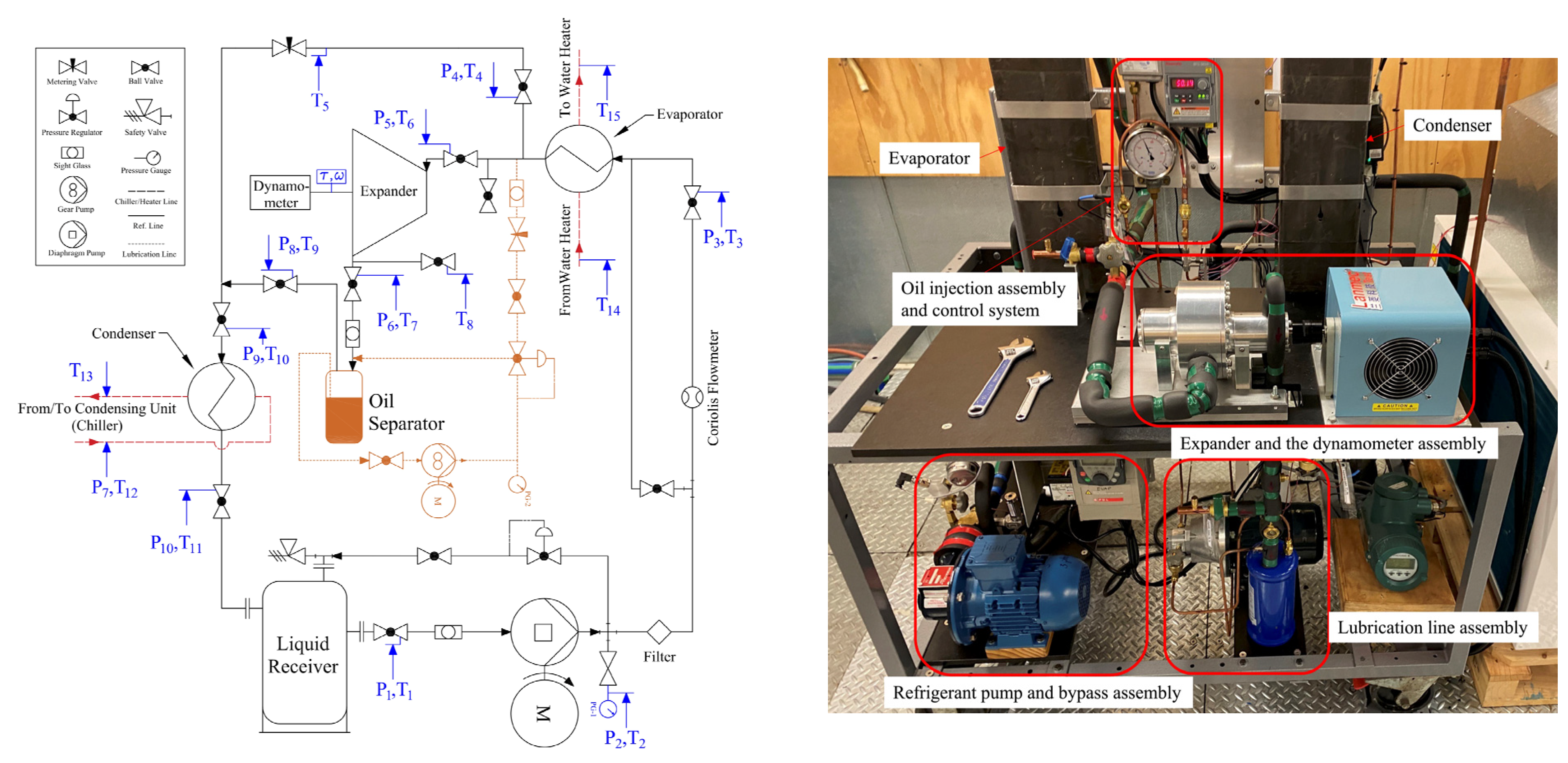
At the premises of the Department of Mechanical and Mechatronics Engineering of the University of Auckland, New Zealand, a micro-scale ORC system test bench was developed, and an M-RVE prototype was tested. R134a [15] and POE (Emkarate-RL46H) [22] were used as the working fluid and lubricant oil, respectively. The test rig included an oil separator circuit, as reported in Figure 1 (orange lines represent the oil circuit), which illustrates the schematic and piping and instrumentation diagram of the test rig used for this study. In this diagram, the locations where the pressure and temperature were measured are shown by P and T, corresponding to pressure and temperature measurement devices.
The M-RVE prototype was directly coupled to a dynamometer with a hysteresis brake to control and measure its speed and torque (Figure 1 (right)). Two 10 kW brazed plate heat exchangers were used as the evaporator and condenser. The heat was supplied to the evaporator using a 9-kW water heater, and a 10-kW chiller was used as the heat sink. A lubrication system was integrated to feed the expander at the inlet. The flow rate and pressure of the lubricant were controlled using a needle valve and a back pressure regulator, respectively. After lubricating the expander, the oil was separated from the refrigerant in a separator and travelled to the expander inlet using an oil pump. The lubrication line assembly is shown in Figure 1 (right). The refrigerant flow rate was measured using a Coriolis mass flow meter after the refrigerant pump, and the temperature and pressure were measured at the desired points using T-type thermocouples and pressure transducers. The accuracy and specification of the measurement devices are reported in Table 1.
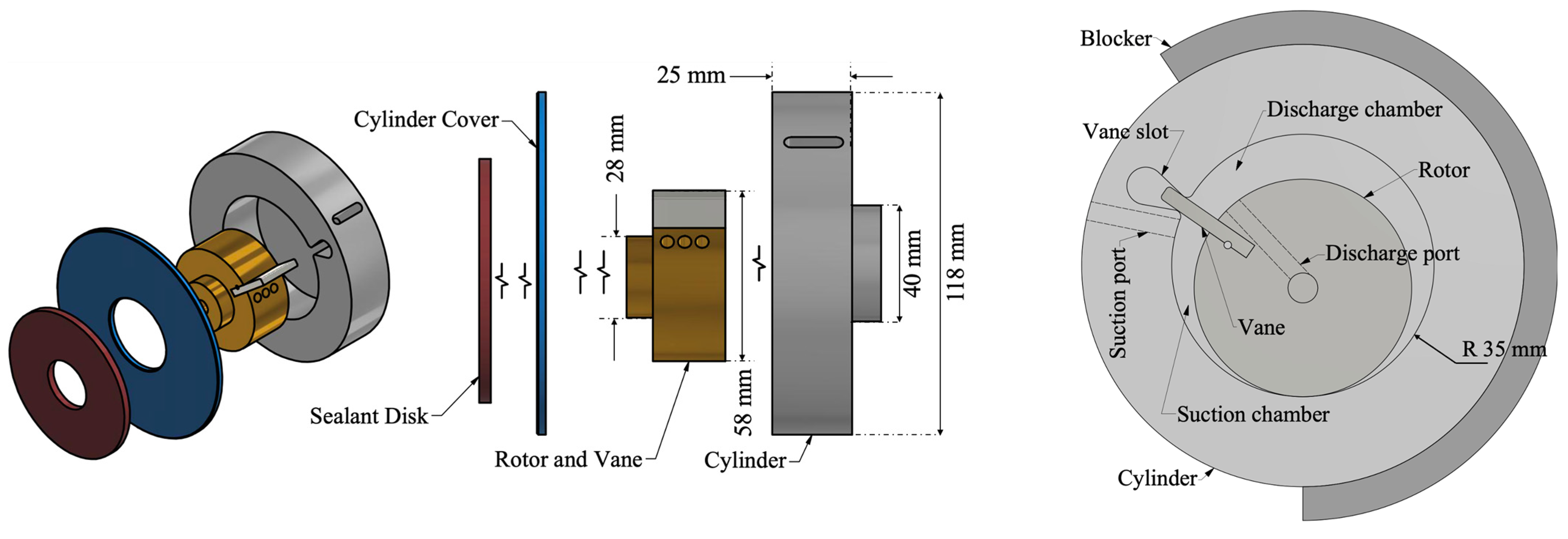
The M-RVE prototype consists of a rotor, a cylinder, a vane, and a stationary suction timing mechanism called a blocker. The revolving vane mechanism was initially introduced as a compressor in 2006 [23] and then studied as an expander replacing the expansion valve in refrigeration systems (the RV-I prototype) [24] and ORC applications (the M-RVE prototype) [25]. In this mechanism, the vane is attached to the rotor, and the rotor is positioned eccentrically to the cylinder, which creates the working chambers. When the suction port on the cylinder is uncovered by the stationary blocker, the suction process begins and continues until the suction port is covered by the blocker. Then, the working fluid undergoes the expansion process. At the end of one revolution, the expanded working fluid enters the discharge chamber and leaves the expander via the discharge ports on the rotor. Figure 2 illustrates the schematic of the M-RVE prototype. In the current study, a brand-new Teflon-made end-face sealant disk was used in the M-RVE prototype as signs of wear were observed on the disk when disassembled [15]. Moreover, the rotary seals were replaced.

2.2. Experimental Procedure and Data Reduction

A total of 120 data points were collected in a steady-state condition in this study through different scenarios. The refrigerant mass flow rate was adjusted by changing the refrigerant pump frequency (20 and 25 Hz), the expander rotational speed was controlled by the dynamometer (ranging from 1070 to 1930 rpm), and the expander suction temperature was imposed by changing the heat supply temperature (ranging from 50 °C to 70 °C).
To investigate the impact of oil on the performance of the M-RVE prototype, the data were collected with different ranges of the OCR through the expander, defined as the ratio of the oil mass flow rate to the total (refrigerant-oil mixture) mass flow rate as shown in Equation (1). This study’s OCR ranges from 0.05% to 8%. It should be noted that the OCR does not represent the oil charge within the ORC system.
O C R = m ˙ o i l m ˙ t
To describe the performance of the M-RVE prototype, the filling factor (FF) and the isentropic efficiency ( η i s ) were used as defined in Equations (2) and (3). The FF is defined as the ratio between the measured and the theoretical volume flow rates, while the isentropic efficiency is the ratio between the shaft power and the isentropic power associated with the measured refrigerant mass flow rate. In Equation (2), N e x p is the expander shaft speed, and V s u , e x p is the suction volume of the expander. Also, in Equation (3), the entropy at the inlet and outlet of the expander is the entropy of the refrigerant-oil mixture, discussed in this section.
F F = m ˙ m e a s u r e d / ρ m e a s u r e d V s u , e x p × N e x p 60
η i s = W ˙ s h a f t m ˙ r e f · h i n h o u t , i s
Table 2 reports the ranges of the imposed parameters and obtained performances during the tests.
In Equation (2), V s u , e x p can be obtained from the design and timing of the suction port in the prototype. This would also define the built-in volume ratio (BVR), which is the ratio of the discharge volume to the suction volume of the expander, as shown below. In this study, the V s u , e x p and BVR for the M-RVE prototype is 15.71 cc/rev and 1.9, respectively.
B V R = V d i s , e x p V s u , e x p
To assess the impact of the expander oil on the evaporator and the expander, the thermodynamic properties of the refrigerant-oil mixture at various operating conditions are required. This study tested an ORC system with an oil separator loop, so the expander lubricant was not presented in the rest of the system. Hence, the impact of the expander oil on the performance of the other main components could not be observed experimentally. Nevertheless, at the micro-to-small scale, a dedicated oil circuit introduces further complexity to the system with potentially limited benefits to its performance.
The main impact of the expander oil on other components is because of the misinterpretation of their performance indicators instead of a tangible change in the measured data, as mentioned in the last paragraph of the introduction. The misunderstanding is because of the usual practice of neglecting the refrigerant-oil mixture properties and assuming the pure refrigerant properties, as in most papers in the literature. Hence, the impact of the expander oil on the evaporator thermal power is assessed here, assuming that the same OCR of the expander is valid for the evaporator and the measured temperature and pressure at the evaporator inlet and outlet with the pure fluid are valid when the mixture passes through the evaporator.
The refrigerant-oil properties are calculated using Grebner and Crawford’s model [21] and are represented in the following. Among the parameters, the refrigerant miscibility of the refrigerant-oil mixture indicates how the oil moves in the system. In a two-phase mixture, the oil remains in its liquid phase due to its higher boiling point than the one of the refrigerant, and it enriches into the liquid refrigerant as the vapor quality increases [19]. Assuming that the oil is only mixed with the liquid refrigerant, the refrigerant-oil mixture would consist of gas refrigerant, liquid refrigerant, and lubricant, constituting a two-phase three-component mixture. Hence, the mixture’s mass flow rate and the refrigerant miscibility can be calculated using Equations (5) and (6), respectively.
m ˙ t = m ˙ r e f , l + m ˙ o i l + m ˙ r e f , v
w r e f = m ˙ r e f , l m ˙ r e f , l + m ˙ o i l
As for the refrigerant miscibility, it can be correlated with the mixture temperature and pressure and the saturated temperature of the refrigerant, and it is calculated implicitly using the following empirical equation [26]:
T T s a t ( p ) T s a t ( p ) = ( 1 w r e f )   ( A + B p )
where T s a t ( p ) is the saturation temperature of the refrigerant at pressure ( p ), and A and B are the coefficients calculated using the equations below. The empirical coefficients for these equations are presented in Table 3 for the R134a-POE mixture.
A = a 1 + a 2 w r e f
B = a 3 + a 4 w r e f + a 5 w r e f + a 6 w r e f 1.5 + a 7 w r e f 2
The enthalpy of the refrigerant-oil mixture is equal to the summation of the mass-weighted enthalpy of the components since the enthalpy of the mixing is negligible, assuming an ideal mixing process. Hence, the mole fraction of the pure substances is the same as the substances in the mixture. Therefore, the enthalpy of the mixture is calculated as:
h m i x = x i h i
where x i is the mole fraction of the components in the mixture. For the refrigerant-lubricant mixture with liquid lubricant and refrigerant in the liquid and gas phase, Equation (10) can be rewritten as below:
m ˙ t · h m i x = m ˙ r e f , l · h r e f , l + m ˙ o i l · h o i l + m ˙ r e f , v · h r e f , v
The above equation can be expressed in terms of refrigerant miscibility and OCR as shown below [19]:
h m i x = w r e f · O C R ( 1 O C R ) 1 w r e f O C R + w r e f · O C R h r e f , l + O C R · h o i l + ( 1 O C R w r e f ) ( 1 O C R ) 1 w r e f O C R + w r e f · O C R h r e f , v
The same approach as Equation (10) is used to calculate the mixture entropy. The entropy of the refrigerant-oil mixture is equal to the sum of the mass-weighted entropy of the components. Hence, Equation (12) can be rewritten regarding refrigerant miscibility and OCR using the oil and refrigerant entropies as in Equation (13). The calculation of oil properties is presented in Appendix A.
s m i x = w r e f · O C R ( 1 O C R ) 1 w r e f O C R + w r e f · O C R s r e f , l + O C R · s o i l + ( 1 O C R w r e f ) ( 1 O C R ) 1 w r e f O C R + w r e f · O C R s r e f , v
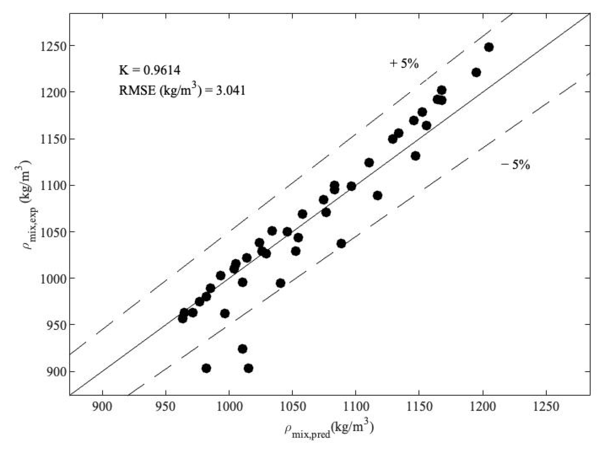
The mixture density is calculated using Equation (14) according to [19] to reconcile the calculated mass flow rate of the mixture using the measured volumetric flow rate. The coefficient K p is the density correction factor depending on the liquid temperature and its composition. Optimization was performed on the experimental data presented in [21] for the R134a-POE mixture to obtain the K p aiming at minimising the difference between the calculated and experimental densities. The optimisation results are presented in Figure 3, resulting in a constant K p equal to 0.9529 for the range of 0.069 < w r e f < 0.832 and 1   ° C < T < 88   ° C .
ρ m i x = 1 K p ρ o i l 1 + w r e f ρ o i l ρ r e f , l 1
Since the experimental studies come with uncertainties due to the precision of the measurement tools and the experimental data, the combined uncertainty associated with parameter U is obtained using Equation (15). U is a function of several independent variables of u i , j is the confidence level indicator (equal to 2 corresponding to a 95% level of confidence in this study), and δ u i is the uncertainty associated with the parameter k i [28]. Table A1 shows the average uncertainties of the measured and calculated parameters which meet the tolerance range required by the design specifications.
δ U = j · i U k i δ u i 2

3. Results and Discussion

The impact of the lubricant oil on the performance of the expander in terms of its isentropic and volumetric efficiencies is presented in this section. Following the assumptions described in Section 2, an estimation of the effect of the lubricant oil on the evaporator is also presented.

3.1. Impact of the Lubricant on the M-RVE Prototype

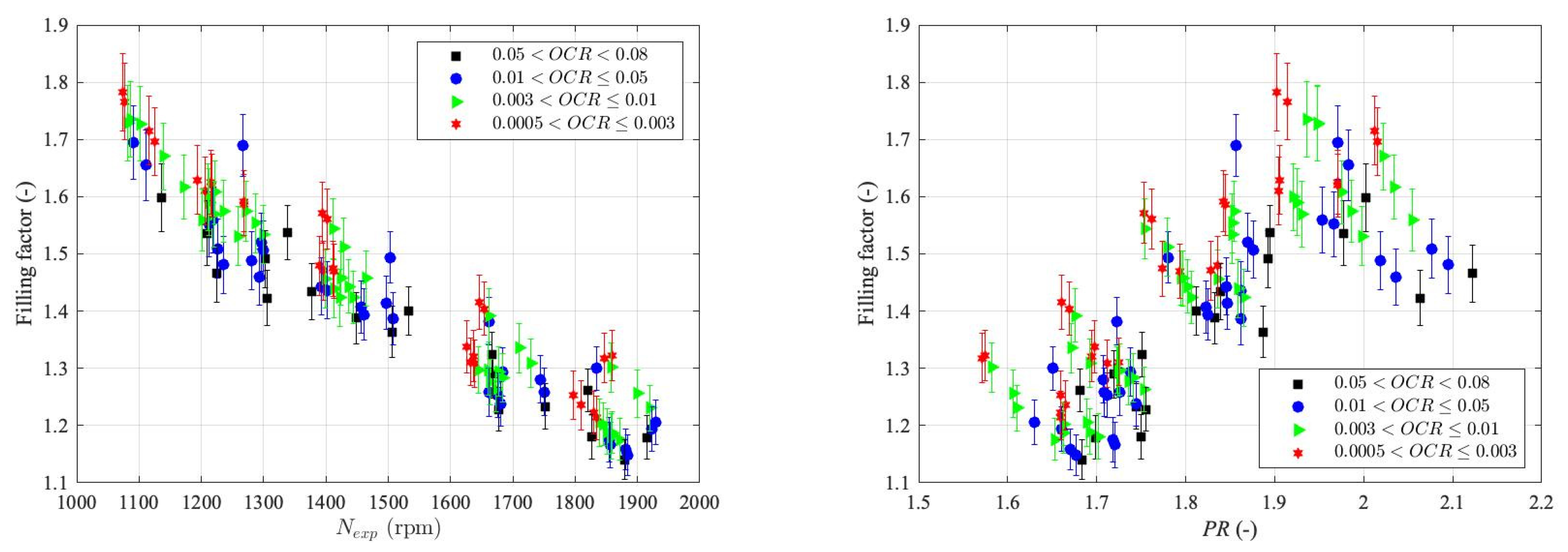
In this study, a wide range of mass flow rates of the lubricant oil is tested to investigate the impact of lubrication on the FF, shaft power, and η i s using the OCR parameter. Figure 4 (left) demonstrates the changes in FF at different shaft speeds for various ranges of OCRs. Two general trends are observed: (1) the FF drops as the shaft speed increases due to the lower leakages at the higher shaft speeds; (2) the FF drops as the OCR increases at constant shaft speeds, which is due to a better lubrication effect at the internal leakage paths leading to a lower leakage and consequently a lower FF. In addition, the FF experienced a moderate drop when the OCR was increased in a wide range from 0.05% to 8% at constant shaft speeds. However, this drop was negligible for OCRs higher than 1%.
Figure 4 (right) demonstrates the changes in FF at different pressure ratios (PRs) for different ranges of OCRs. At a fixed OCR, the FF increases with an increase in PR. This is due to a higher PR across the leakage paths leading to higher leakages. Moreover, it is observed that higher PRs are achieved with higher OCRs. The FF ranged from 1.1 to 1.8 in this study, where the lowest FF corresponded to a PR of 1.7, expander suction temperature of 54 °C, and shaft speed of 1879 rpm.
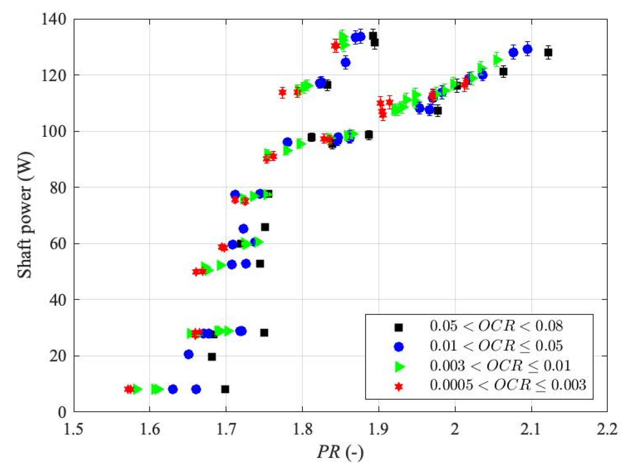
Figure 5 shows the shaft power versus the PRs at different OCRs. For the same OCR, the shaft power increases when PR increases. This is because a higher body force on the vane leads to higher torque at a similar shaft speed. However, as the OCR increases, insignificant changes are observed in the power output.
Several parameters are involved in calculating the expander isentropic efficiency considering mixture properties: the expander shaft power, the refrigerant mass flow rate, the mixture enthalpy at the inlet, and the mixture isentropic enthalpy at the outlet. The mixture enthalpy at the expander inlet is calculated using Equation (12). For the mixture isentropic enthalpy at the outlet, Equation (16) is solved to find the isentropic mixture temperature ( T m i x , i s ) at the expander outlet pressure. Then, the mixture isentropic enthalpy at the expander outlet is calculated using Equation (12) using T m i x , i s .
s s u , e x p s d i s , e x p ( T m i x , i s , p d i s , e x p ) = 0
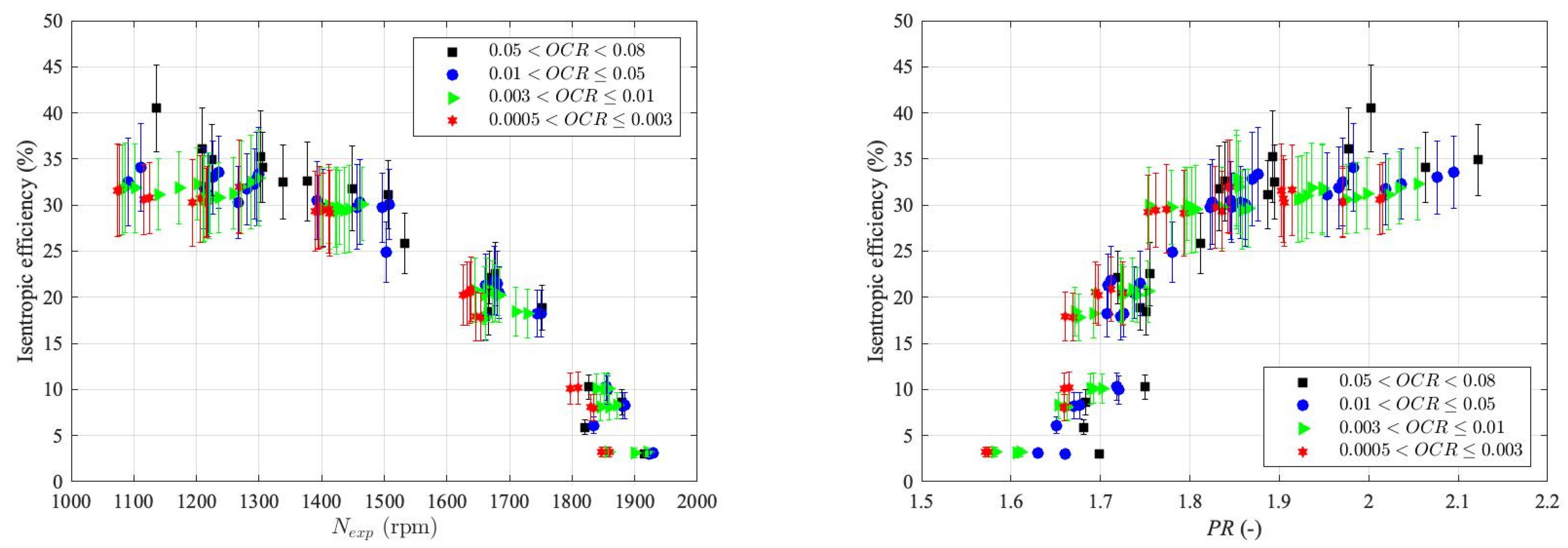
Figure 6 (left) illustrates the changes in the isentropic efficiency by the shaft speed at different OCRs. The isentropic efficiency drops at higher shaft speeds for similar OCRs. This is mainly due to the higher frictional loss at higher expander shaft speeds. Looking at the changes in the isentropic efficiency at different OCRs, it can be observed that although the higher OCR leads to higher PRs and improves the FF, the isentropic efficiency shows insignificant alteration with the change in the OCR. This is due to a negligible change in the shaft power when increasing OCR, as shown in Figure 5.
Figure 6 (right) illustrates the isentropic efficiency by varying the PR and shaft speed for different OCRs. The isentropic efficiency increases with PR until the values are close to the expander BVR. This is because the higher body force acting on the vane leads to a higher torque value. The isentropic efficiency almost flattens at PRs higher than the expander BVR.
In an ideal case, the working fluid undergoes an ideal expansion from the suction pressure at V s u , e x p to the discharge pressure at V d i s , e x p . In a real scenario, the fluid expands from V s u , e x p at the suction pressure to an alternative pressure ( p i n , e x p ) at V d i s , e x p . The ratio of the suction pressure to this alternative internal pressure is called the built-in pressure ratio (BPR), which is proportional to the B V R γ assuming working fluid as an ideal gas with a specific heat ratio of γ . If the imposed PR by the system is lower than the BPR (which is slightly higher than BVR), the working fluid undergoes an over-expansion.
On the other hand, the PRs higher than the BPR leads to under-expansion of the working fluid. In this study, the refrigerant experiences over-expansion in most cases leading to low isentropic efficiencies. As the PR increases to the BPR, the isentropic efficiency increases and flattens. It should be noted that the isentropic efficiency is expected to drop at PRs higher than the BPR due to the under-expansion losses. However, higher PRs were not achieved in this study due to the capacities and temperature limits of the heat source and sink. The range of the isentropic efficiency is 2.9–41% in this study.
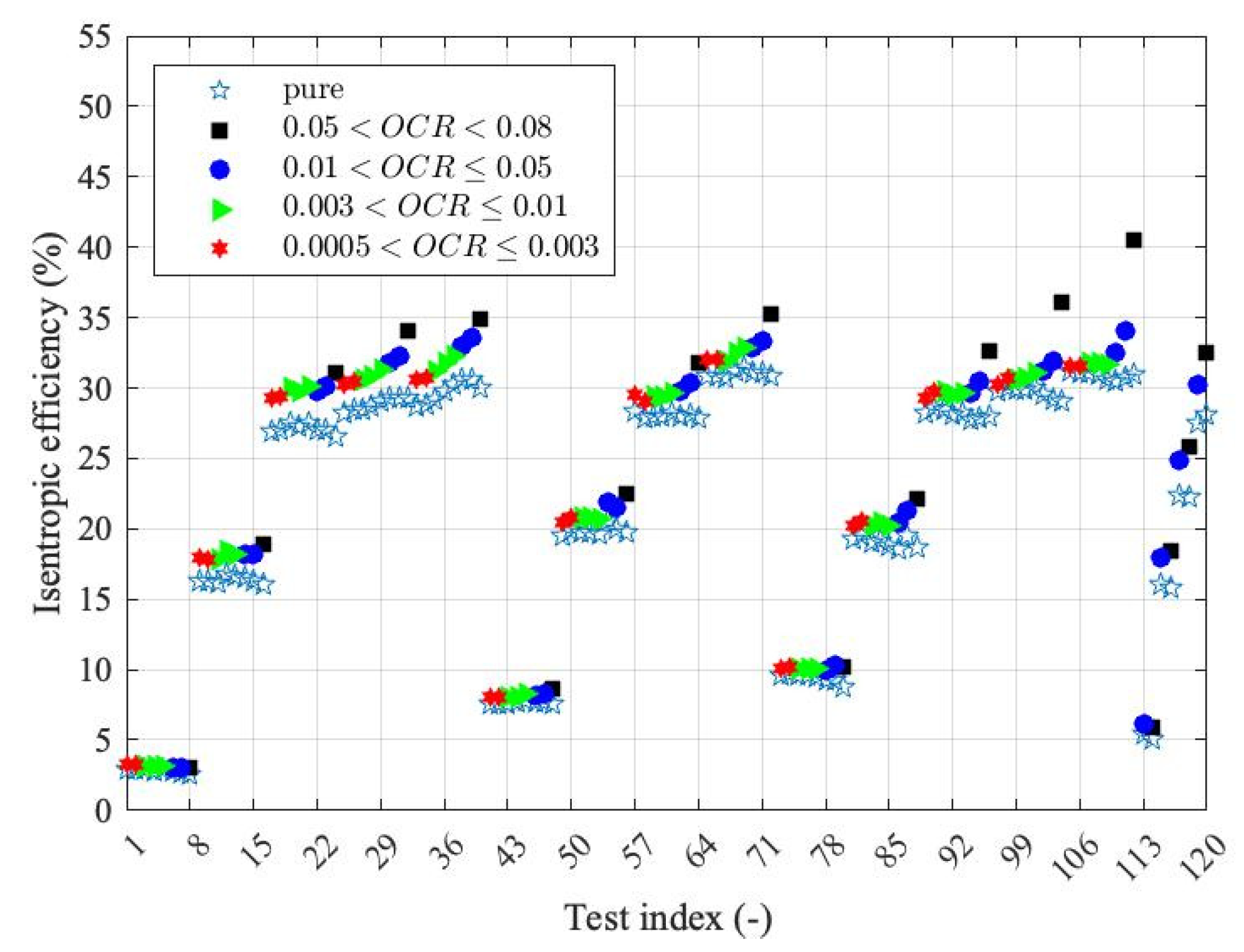
Figure 7 shows the expander isentropic efficiency considering the refrigerant-oil mixture properties compared to the one regarding the pure refrigerant properties. The results suggest that the isentropic efficiency of the refrigerant-oil mixture is calculated higher than the pure refrigerant in all cases. The difference is bigger in higher OCRs. Therefore, lubricant oil enhances the expander isentropic efficiency, albeit to a limited extent.

3.2. Impact of the Refrigerant-Oil Mixture on the Evaporator

Although a higher OCR does not change the isentropic efficiency of the expander significantly, the increased amount of lubricant may impact the evaporator’s performance. When no oil separator loop is implemented, the refrigerant-oil mixture travels through the ORC. As mentioned in Section 2, the current experimental setup was designed with an oil separator loop to circulate the lubricant just through the expander. Still, it is helpful to predict the effect of different OCRs on the performance of the evaporator in case simpler configurations are required to reduce the overall cost of the system and to avoid a dedicated oil circuit to reduce the system’s complexity.
To investigate the impact of the mixture on the performance of the evaporator, it is necessary to calculate the mixture properties, including the refrigerant miscibility, density, and enthalpy, according to the methodology discussed in Section 2.2.
A few assumptions are made for this analysis: (1) the OCR truly represents the amount of the oil travelling through the ORC components, i.e., the same measured oil flow rate at the expander inlet travels through the refrigerant pump, evaporator and condenser; (2) when the refrigerant-oil mixture travels through the pump, the volumetric efficiency of the pump at a given pump speed remains the same as the calculated values using the pure refrigerant properties. It is worth mentioning that the amount of lubricant flowing through the system differs from the lubricant oil and refrigerant charge. In this work, the amount of lubricant injected into the expander inlet could be adjusted irrespective of the charge amount. With these assumptions, the mixture mass flow rate through the ORC system can be calculated:
η v , p u m p m i x = η v , p u m p p u r e N s h a f t m ˙ p u r e , m e a s m ˙ m i x , c a l c = ρ p u r e ρ m i x
Given the calculated mixture mass flow rate and the enthalpies at the inlet and outlet of the evaporator for the pure and mixed refrigerant, the evaporator thermal power is calculated as the following:
Q ˙ e v m i x = m ˙ m i x , c a l c h o u t h i n
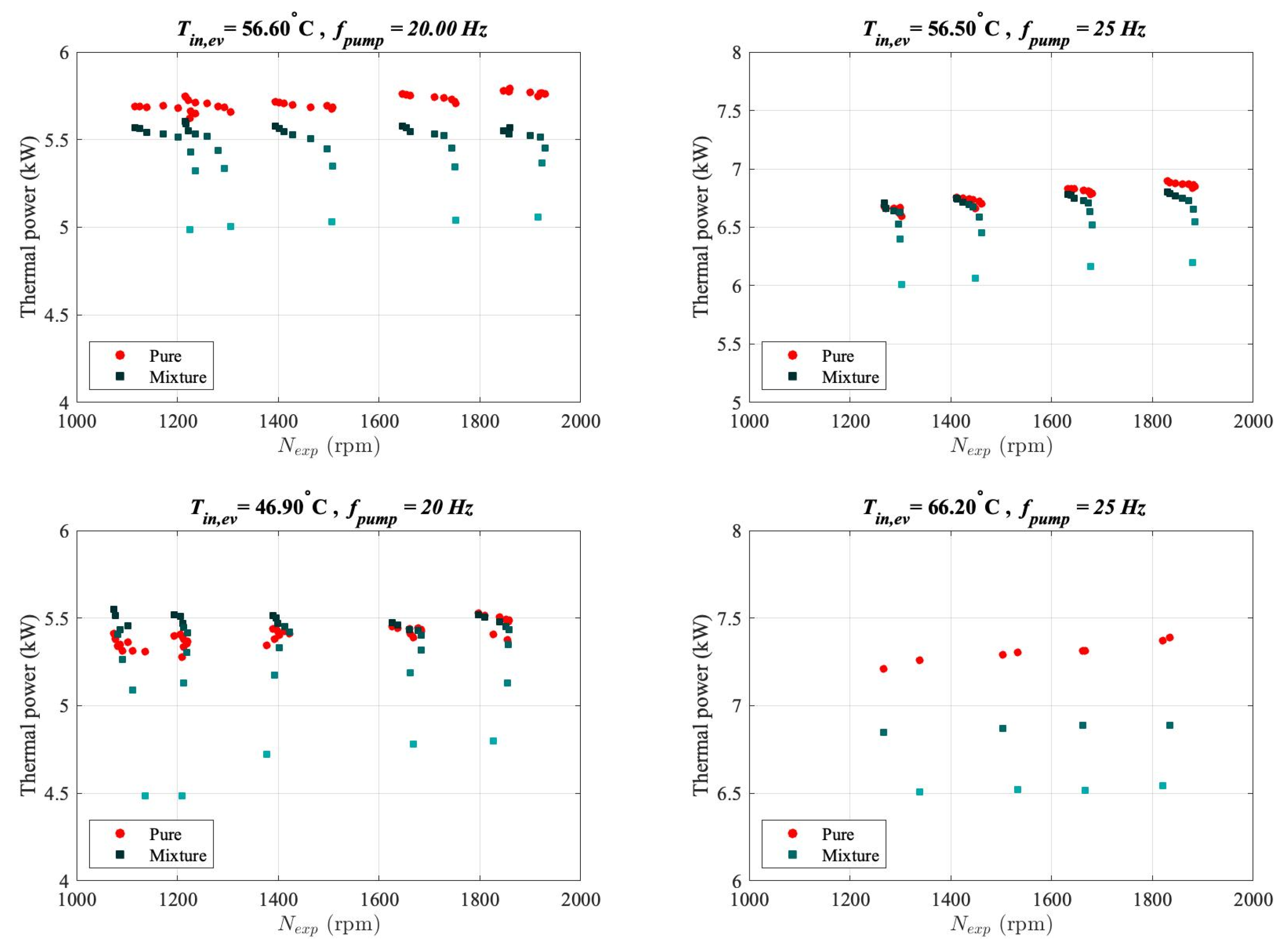
Figure 8 represents the evaporator thermal power by the pure refrigerant and refrigerant-oil mixture in the evaporator at different heat source temperatures, refrigerant mass flow rate, and OCR (oil mass flow rate) versus the expander shaft speed. The results for each scenario demonstrate a significant drop in the evaporator thermal power as the OCR increases. To quantify this, the capacity loss for the evaporator is obtained using the following equation [19], where Q ˙ e v p u r e is the evaporator thermal power calculated using the pure refrigerant properties.
C a p a c i t y   l o s s = Q ˙ e v p u r e Q ˙ e v m i x Q ˙ e v p u r e × 100
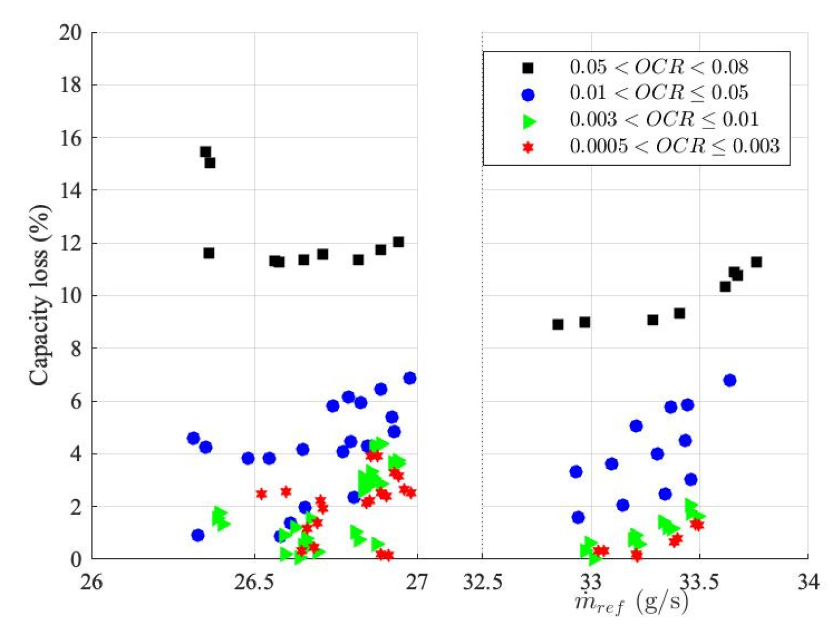
Figure 9 shows the capacity loss at different mass flow rates of the mixture. The impact of the oil on the evaporator capacity loss is significant at higher OCRs. The minimum capacity loss at OCRs higher than 5% is 8.8%, while the maximum capacity loss of almost 6.8% is predictable for OCRs lower than 5%.
The literature does not focus on the impact of the oil on the boiling heat transfer coefficient, as the majority reported a decrease for oil concentrations above 1%, which was drastic for concentrations above 5% [29]. However, some reported increments in the boiling heat transfer coefficient, such as in [30,31], where an increment was observed for concentrations around 3%. The impact of oil on boiling heat transfer coefficient may depend on several parameters like OCR, refrigerant miscibility, the oil type, the working fluid, the heat flux, the mass flow rate, and the tube or channel geometry. These parameters affect the flow pattern of the boiling flow at the end, which is determinative of the conclusion about the impact of the oil on the evaporator capacity. Nonetheless, the evaporator capacity is penalised in all cases with different OCRs, as shown in Figure 9.
Considering the different impacts of the expander oil on the expander and evaporator performance indicator, an almost optimum OCR can be suggested for the M-RVE in ORC systems. At OCRs higher than 1%, changes in the expander FF and the shaft power were negligible, and the expander isentropic efficiency improved considerably with OCR. Considering the significant drop in the evaporator capacity for OCRs of more than 1%, it can be concluded that an OCR of about 1% would be suitable for the M-RVE prototype in micro-scale ORC systems. However, as Equation (1) suggests, the OCR is a function of the oil and refrigerant mass flow rates. It does not represent the mass charge ratio of the lubricant to the refrigerant, and it depends on the internal leakages of the expander. The internal leakages depend on the leakage clearances, working temperature, and the expander shaft speed. For the exact oil and refrigerant charges and at a constant oil mass flow rate, a higher shaft speed results in a lower OCR. Therefore, the OCR is indicative for predicting the near optimum mass charge ratio of the lubricant to refrigerant at the design shaft speed and for specific refrigerant, lubricant, and expander types. A more holistic conclusion requires further experimental studies to observe the impact of these parameters on the near-optimum OCR and the associated mass charge ratio of the lubricant to the refrigerant.

4. Conclusions

In this study, an M-RVE prototype was tested in a micro-scale ORC test rig with an adjustable oil mass flow rate. The impacts of the lubricant oil on the performances of the M-RVE prototype were investigated in terms of expander FF, shaft power, and isentropic efficiency within a wide range of OCRs. The ORC system presented in this study only had an oil separator loop circulating the oil through the expander. Hence, the impact of the oil on the performance of the evaporator, which significantly affects the overall efficiency of the ORC system, could not be studied experimentally. Nevertheless, at the micro-to-small scale, a dedicated oil circuit introduces further complexity to the system with potentially limited benefits to its performance.
As the main impact of oil on the evaporator is due to misinterpretation of the performance indicators due to low OCRs in practice, the refrigerant-oil mixture properties are used to investigate the evaporator capacity loss. Considering the opposite impact of the lubricant oil on the M-RVE volumetric and isentropic efficiencies and the evaporator thermal power, a compromised value for the OCR is suggested for micro-scale ORC systems. The main findings of this study are summarised in the following:
  • The OCR being altered within a wide range from 0.05% to 8% for constant shaft speeds, the FF demonstrates an insignificant drop for OCRs higher than 1%.
  • It is observed that higher PRs are achieved at higher OCRs. Meanwhile, the shaft power shows a negligible change with the OCR.
  • Although a higher OCR improves the FF, the isentropic efficiency shows insignificant alteration with the change in the OCR.
  • The isentropic efficiency of the refrigerant-oil mixture is higher than pure refrigerant for all scenarios, while this difference increases with increasing the OCR.
  • The evaporator thermal power calculated at different scenarios for pure and refrigerant-oil mixtures dropped significantly as the OCR increased.
  • The minimum evaporator capacity loss at OCRs higher than 5% is 8.8%, while the maximum capacity loss of almost 6.8% is observed for OCRs lower than 5%.
Therefore, due to the negligible changes in the FF, the shaft power, and the isentropic efficiency, and the large drop in the evaporator thermal power for OCRs of more than 1%, this value presents an approximate optimal OCR for the studied M-RVE prototype in the micro-scale ORC rig.
In addition, this study provides indications to consider a more realistic design target for volumetric expanders with the lubrication requirement corresponding to the OCR ≤ 1% instead of dry machines for micro-to-small scale ORC systems. Notably, OCR does not represent the mass charge ratio of the lubricant to the refrigerant, which is one of the boundary conditions defining the ORC systems. OCR can indicate the near-optimum mass charge ratio of the lubricant to the refrigerant. Despite this work suggests a near optimum OCR of 1% for the studied MRVE working with R134a and POE mixture, a holistic conclusion about the near optimum OCRs for volumetric expanders and the associated near optimum mass charge ratio of the lubricant to refrigerant requires further studies with other types of volumetric expanders, working fluids, and lubricants.
Author Contributions

Conceptualization, A.N.; methodology, A.N.; formal analysis, A.N.; data curation, A.N.; writing—original draft preparation, A.N. and R.M.; writing—review and editing, R.M., L.C. and A.S.; supervision, A.S.; funding acquisition, A.S. and A.N. All authors have read and agreed to the published version of the manuscript.

Funding

This research was funded internally by the Faculty Research Development Fund (FRDF) at the University of Auckland, Project number: 3724982.

Data Availability Statement

The data presented in this study are available on request from the first author, due to privacy restrictions.

Acknowledgments

The Authors acknowledge the contribution of Jos Spaans from the University of Auckland in collecting the experimental data in this study.

Conflicts of Interest

The authors declare no conflict of interest.

Nomenclature

B V R Built-in volume ratio (-)
C p Mass specific heat (J.kg−1.K−1)
F F Filling factor (-)
h Enthalpy (J. kg−1)
K p Density correction factor (-)
m ˙ Mass flow rate (g.s−1)
N e x p Shaft speed (rpm)
O C R Oil circulation rate (-)
p Pressure (bar)
P R Pressure ratio (-)
Q ˙ e v Evaporator thermal power (W)
TTemperature (°C)
T 0 Reference temperature (°C)
sMass specific entropy (J.kg−1.K−1)
U ( u i ) The arbitrary function of the independent variable u i
V Volume (m3)
V ˙ Volume flow rate (m3.s−1)
W ˙ s h a f t Shaft power (W)
w r e f Refrigerant miscibility (-)
x i Mole fraction of component i (-)
Greek symbols
η i s Isentropic efficiency (-)
η v Volumetric efficiency (-)
η Dynamic viscosity (Pa.s)
ρ Density (kg.m−3)
Subscripts/superscripts
calcCalculated
CFCold fluid
disDischarge
evevaporator
HFHot fluid
inInlet
isIsentropic
lLiquid
mixMixture
outOutlet
refRefrigerant
satSaturation
SCSubcooling
SHSuperheating
suSuction
tTotal
thTheoretical
vVapour
expexpander

Appendix A

The Emkarate-RL46H oil properties are calculated using the table of properties provided by the manufacturer.
C p = 2.098 × ( T + 273.15 ) + 1408
η = 7.35 × T 1.324 0.0114
ρ = 7314 × T + 991.2
The following correlations were also found to fit the tabular data, where T 0 is assumed 0 °C at which h T 0 and s T 0 are equal to zero. In Equations (A1)–(A5), T is measured in °C.
Δ h T = C p T d T = 1.049 × T T 0 2 + 1408 × T T 0
Δ s T = C p T T d T = 2.098 × T T 0 + 1408 × ln T + 273.15 T 0 + 273.15

Appendix B

The average uncertainty range of the measured and calculated parameters is shown in the table below:
Table A1. Average uncertainty range of measured and calculated data.
T (°C) p (bar) m ˙ r e f (g/s) N e x p (rpm) W ˙ s h a f t (W) F F (-) η i s (%)
0.3000.1350.02011.5621.4220.04773.360

References

  1. Imran, M.; Haglind, F.; Asim, M.; Alvi, J.Z. Recent research trends in organic Rankine cycle technology: A bibliometric approach. Renew. Sustain. Energy Rev. 2018, 81, 552–562. [Google Scholar] [CrossRef] [Green Version]
  2. Tchanche, B.F.; Lambrinos, G.; Frangoudakis, A.; Papadakis, G. Low-grade heat conversion into power using organic Rankine cycles—A review of various applications. Renew. Sustain. Energy Rev. 2011, 15, 3963–3979. [Google Scholar] [CrossRef]
  3. Pereira, J.S.; Ribeiro, J.B.; Mendes, R.; Vaz, G.C.; André, J.C. ORC based micro-cogeneration systems for residential application—A state of the art review and current challenges. Renew. Sustain. Energy Rev. 2018, 92, 728–743. [Google Scholar] [CrossRef]
  4. Talluri, L.; Dumont, O.; Manfrida, G.; Lemort, V.; Fiaschi, D. Experimental investigation of an Organic Rankine Cycle Tesla turbine working with R1233zd(E). Appl. Therm. Eng. 2020, 174, 115293. [Google Scholar] [CrossRef]
  5. Campana, C.; Cioccolanti, L.; Renzi, M.; Caresana, F. Experimental analysis of a small-scale scroll expander for low-temperature waste heat recovery in Organic Rankine Cycle. Energy 2019, 187, 115929. [Google Scholar] [CrossRef]
  6. Moradi, R.; Habib, E.; Villarini, M.; Cioccolanti, L. Assumption-free modeling of a micro-scale organic Rankine cycle system based on a mass-sensitive method. Energy Convers. Manag. 2021, 245, 114554. [Google Scholar] [CrossRef]
  7. Francesconi, M.; Briola, S.; Antonelli, M. A Review on Two-Phase Volumetric Expanders and Their Applications. Appl. Sci. 2022, 12, 10328. [Google Scholar] [CrossRef]
  8. Dumont, O.; Parthoens, A.; Dickes, R.; Lemort, V. Experimental investigation and optimal performance assessment of four volumetric expanders (scroll, screw, piston and roots) tested in a small-scale organic Rankine cycle system. Energy 2018, 165, 1119–1127. [Google Scholar] [CrossRef] [Green Version]
  9. Imran, M.; Usman, M.; Park, B.-S.; Lee, D.-H. Volumetric expanders for low grade heat and waste heat recovery applications. Renew. Sustain. Energy Rev. 2016, 57, 1090–1109. [Google Scholar] [CrossRef]
  10. Park, B.-S.; Usman, M.; Imran, M.; Pesyridis, A. Review of Organic Rankine Cycle experimental data trends. Energy Convers. Manag. 2018, 173, 679–691. [Google Scholar] [CrossRef]
  11. Fatigati, F.; Di Bartolomeo, M.; Cipollone, R. On the effects of leakages in Sliding Rotary Vane Expanders. Energy 2020, 192, 116721. [Google Scholar] [CrossRef]
  12. Fatigati, F.; Di Bartolomeo, M.; Di Battista, D.; Cipollone, R. A dual-intake-port technology as a design option for a Sliding Vane Rotary Expander of small-scale ORC-based power units. Energy Convers. Manag. 2020, 209, 112646. [Google Scholar] [CrossRef]
  13. Giuffrida, A.; Valenti, G.; Palamini, D.; Solazzi, L. On the conceptual design of the novel balanced rolling piston expander. Case Stud. Therm. Eng. 2018, 12, 38–46. [Google Scholar] [CrossRef]
  14. Krishna, A.; Bradshaw, C.R.; Groll, E.A. Analysis of a rotating spool expander for organic Rankine cycles in heat recovery applications. In Proceedings of the International Compressor Engineering Conference, West Lafayette, IN, USA, 10–14 July 2014. [Google Scholar]
  15. Naseri, A.; Moradi, R.; Norris, S.; Subiantoro, A. Experimental investigation of a revolving vane expander in a micro-scale organic Rankine cycle system for low-grade waste heat recovery. Energy 2022, 253, 124174. [Google Scholar] [CrossRef]
  16. Lei, B.; Wu, Y.-T.; Wang, W.; Wang, J.-F.; Ma, C.-F. A study on lubricant oil supply for positive-displacement expanders in small-scale organic Rankine cycles. Energy 2014, 78, 846–853. [Google Scholar] [CrossRef]
  17. Zhou, N.; Wang, X.; Chen, Z.; Wang, Z. Experimental study on Organic Rankine Cycle for waste heat recovery from low-temperature flue gas. Energy 2013, 55, 216–225. [Google Scholar] [CrossRef]
  18. Yang, J.; Yu, B.; Ye, Z.; Shi, J.; Chen, J. Experimental investigation of the impact of lubricant oil ratio on subcritical organic Rankine cycle for low-temperature waste heat recovery. Energy 2019, 188, 116099. [Google Scholar] [CrossRef]
  19. Moradi, R.; Villarini, M.; Habib, E.; Bocci, E.; Colantoni, A.; Cioccolanti, L. Impact of the expander lubricant oil on the performance of the plate heat exchangers and the scroll expander in a micro-scale organic Rankine cycle system. Appl. Therm. Eng. 2021, 189, 116714. [Google Scholar] [CrossRef]
  20. Dickes, R. Charge-Sensitive Methods for the off-Design Performance Characterization of Organic Rankine Cycle (ORC) Power Systems. Ph.D. Dissertation, Université de Liège, Liège, Belgium, 2019. Available online: https://hdl.handle.net/2268/233945 (accessed on 7 June 2023).
  21. Grebner, J.J. The Effects of Oil on the Thermodynamic Properties of Dichlorodifluoromethane (R-12) and Tetrafluoroethane (R-134a); Air Conditioning and Refrigeration Center, College of Engineering, University of Illinois at Urbana-Champaign: Champaign, IL, USA, 1992. [Google Scholar]
  22. CPI Fluid Engineering. Emkarate RL Lubricant. 2022. Available online: https://www.cpifluideng.com/emkarate-rl/ (accessed on 1 July 2022).
  23. Teh, Y.; Ooi, K.T. Design and friction analysis of the revolving vane compressor. In Proceedings of the International Compressor Engineering Conference, West Lafayette, IN, USA, 17–20 July 2006. [Google Scholar]
  24. Subiantoro, A. Development of a Revolving Vane Expander. Ph.D. Dissertation, Nanyang Technological University, Singapore, 2012. [Google Scholar] [CrossRef]
  25. Naseri, A. Design and Development of a Modified Revolving Vane Expander for the Implementation in Micro-ORC Systems. Ph.D. Dissertation, The University of Auckland, Auckland, New Zealand, 2021. Available online: https://hdl.handle.net/2292/60346 (accessed on 7 June 2023).
  26. Naseri, A.; Norris, S.; Subiantoro, A. Theoretical modelling and Experimental investigation of the Modified Revolving Vane Expander (M-RVE). Energy Convers. Manag. 2021, 252, 114997. [Google Scholar] [CrossRef]
  27. Naseri, A.; Norris, S.; Subiantoro, A. Experimental investigation of a prototype semi-dry revolving vane expander: Design challenges and performance criteria. Energy 2020, 205, 118063. [Google Scholar] [CrossRef]
  28. Yu, J.; Zhang, T.; Qian, J. Electrical Motor Products: International Energy-Efficiency Standards and Testing Methods; Woodhead Publishing: Sawton, UK, 2011. [Google Scholar] [CrossRef]
  29. Bandarra Filho, E.P.; Cheng, L.; Thome, J.R. Flow boiling characteristics and flow pattern visualization of refrigerant/lubricant oil mixtures. Int. J. Refrig. 2009, 32, 185–202. [Google Scholar] [CrossRef]
  30. Schlager, L.; Pate, M.; Bergles, A. Performance Predictions of Refrigerant-Oil Mixtures in Smooth and Internally Finned Tubes--Part I: Literature Review, Presented at Winter Meeting, American Society of Heating, Refrigerating, and Air-Conditioning Engineers, Atlanta, GA, February 10–14, 1990. ASHRAE Trans. 1990, 96, 160–169. [Google Scholar]
  31. Eckels, S.J.; Doerr, T.M.; Pate, M.B. In-tube Heat Transfer and Pressure Drop of HFC-134a and Ester Lubricant Mixtures in a Smooth Tube and a Micro-Fin Tube: Part I Evaporation. ASHRAE Trans. 1994, 100, 265–282. [Google Scholar]
Figure 1. The schematic (left) and photo (right) of the ORC test rig and the MRVE retrieved from [15].
Energies 16 05340 g001
Figure 2. The exploded and side view of the M-RVE’s internal components (left), the description of M-RVE’s internal components (right), modified from [26,27].
Energies 16 05340 g002
Figure 3. Calculated and measured mixture density—Dashed lines are the ± 5% error margins (the experimental densities are adopted from [21]).
Energies 16 05340 g003
Figure 4. Expander FF by its shaft speed (left) and PR (right) with different OCRs.
Energies 16 05340 g004
Figure 5. Shaft power of the M-RVE prototype versus the PRs at different OCRs.
Energies 16 05340 g005
Figure 6. The isentropic efficiency of the M-RVE prototype by the shaft speed with different OCRs (left) and the isentropic efficiency of the M-RVE prototype by PR with different OCRs (right).
Energies 16 05340 g006
Figure 7. Isentropic efficiency of the M-RVE prototype considering mixture and pure fluid properties with different OCRs.
Energies 16 05340 g007
Figure 8. The evaporator thermal power at different shaft speeds, and operating conditions—The brighter colours represent higher OCRs for the mixture.
Energies 16 05340 g008
Figure 9. Capacity loss in the evaporator versus the refrigerant mass flow rate.
Energies 16 05340 g009
Table 1. The specification and accuracy of the measurement devices.
ParameterInstrumentResolutionAccuracy
TemperatureType T thermocouple 0.02 °C±0.5 or ±0.4% read value (°C)
PressureEmerson PCN802351 and PCN8023521.4 and 2.3 mbar±1% Full scale (30 and 18 bar)
Emerson PT6N18M1.4 mbar±1.5% Full scale (18 bar)
Trafag NAT82512 mbar±0.5% Full scale (25 bar)
Refrigerant mass flow rateYokogawa RCCS313.4 mg/sec±0.1% read value ± zero Stability/read value
Torque Lanmec HZC 1Q0.0001 N.m<0.5% Full scale (1 N.m)
Expander shaft speedLanmec HZC 1Q60 pulse/rev<0.1% Full scale (20,000 rpm)
Table 2. The ranges of imposed variables and obtained performances.
Imposed Obtained
T H F (°C) T C F (°C) m ˙ r e f (g/s) N e x p (rpm) p s u , e x p (bar) T s u , e x p (°C) W ˙ s h a f t (W) SH (°C)SC (°C) P R F F η i s (%)
45.0–70.05.0–12.026.0–34.01070–19309.0–13.044.0–65.0 1352.0–16.52.0–11.01.5–2.21.1–1.82.9–41.0
Table 3. The empirical coefficient for R134a-POE mixture [21].
a 1 (-) a 2 (-) a 3 (bar−1) a 4 (bar−1) a 5 (bar−1) a 6 (bar−1) a 7 (bar−1)
5.4964676 × 10 2 5.1860596 × 10 2 18.9261 × 10 3 30.8683 × 10 3 16.4510 × 10 3 30.9937 × 10 4 21.7748 × 10 5
Disclaimer/Publisher’s Note: The statements, opinions and data contained in all publications are solely those of the individual author(s) and contributor(s) and not of MDPI and/or the editor(s). MDPI and/or the editor(s) disclaim responsibility for any injury to people or property resulting from any ideas, methods, instructions or products referred to in the content.