Article

Shared Driving Assistance Design Considering Human Error Protection for Intelligent Electric Wheelchairs

1
Department of Vehicle Engineering, National Taipei University of Technology, Taipei 10608, Taiwan
2
IOT Software Department, Compal Electronics, Inc., Taipei 11492, Taiwan
3
Department of Electrical Engineering, National Taipei University of Technology, Taipei 10608, Taiwan
*
Author to whom correspondence should be addressed.
Energies 2023, 16(6), 2583; https://doi.org/10.3390/en16062583
Submission received: 19 January 2023 / Revised: 28 February 2023 / Accepted: 6 March 2023 / Published: 9 March 2023
(This article belongs to the Special Issue Development of Intelligent Electric Vehicles and Smart Transportation)

Abstract

:
To effectively provide the handicapped with mobility aids, studies on the shared autonomy of robotic systems have been widely cultivated. This study proposes an adaptive shared control strategy to realize reliable and safe driving assistance on an intelligent electric wheelchair with protection against human errors. The theoretical framework of the system is analyzed by the linearized reference wheelchair model and stable characteristics of obstacle avoidance behavior can be subsequently derived according to the Lyapunov analysis and Liénard-Chipart criterion. Based on the convex analysis, the relationships between human input and robot control are investigated to determine shared control weights. As such, safety and reliability can be guaranteed. To verify the performances of the proposed approach, human errors including skill-based errors, decision errors, and violations are considered in the experiments. The experimental results based on a comprehensive study show that the proposed method is capable of enhancing driving safety and reducing operation burden in terms of the designed criteria with fluency, smoothness, and time efficiency while protecting the user from human manual errors.

1. Introduction

Mobility inconvenience usually hinders elders or physically inconveniences people to complete activities of daily livings and decreases their will to go outside. The raising problems of negative emotions as well as psychological diseases thus easily occur. One possible solution to this problem is to provide a useful and suitable robotic system to assist this group of people with their daily activity livings. For example, an electric mobile robot can provide a reliable ability to avoid obstacles [1] along with techniques such as path-following, speed planning, and so on. Given the large need for assistance from a rapidly aging population and people with various disabilities, assistive robotic systems have shown great potential in the research community. However, even though an assistive robot can help solve limited mobility, sensory, and cognitive level problems and improve safety for the users, according to [2], it should provide help only when it is needed. In other words, when a fully autonomous robot takes overall control authority, it is reported in [3] that the user would feel unsafe and would try to reclaim control of the system. Hence, a fully autonomous system is not an appropriate solution.
In order to simultaneously address the user’s control authority and the autonomous control of the robot, the idea of shared control is increasingly focused on. A shared control system has features that combine an autonomous agent and a human user by taking advantage of both human intelligence and the agent to aid each other. Thereafter, it has been shown by many contributors that shared control can be applied in many areas, such as walking assistant robots in [4] and semi-autonomous controlled robots in [5]. Involving shared control in a robotic wheelchair can also be commonly seen from the literature, as it is out in [6], that with shared control ability, the robotic wheelchair not only provides self-dominance for the user but also ensures overall security. According to the needs of the wheelchair user, shared control can be categorized into two classes: task-level shared control and servo or execution-level control. The former refers to macro-level control, where control inputs are issued by broad motion commands from the user such as moving along the corridor, moving through an open door, etc. Then, as the robotic wheelchair starts to perform the general tasks according to the commands, the control of the wheelchair is mostly taken over by the robotic system. Macro-level control is widely shown in teleoperation applications. For example, Uratsuji et al. proposed dynamic shared control to increase the comfort for the user and then included an annotated map to adjust control weights of turning velocities [7]. Though task-level control only passively provides autonomous service when a command is requested by the user, it cannot actively handle hazardous situations when unreliable manual control or instantaneous control behavior is given by the user.
As being a cooperative way that is highly accepted and extensively used in human-robot interaction systems, servo-level shared control is regarded as micro-control. The feasible control input is generated with the combination of the robot itself and the user at any sample point. As shown in (1), u s is the controlling of the overall system, while u r and u h are the inputs from the robot and the human user, respectively. α s , which ranges from 0 to 1, is responsible for adjusting the ratio of u r and u h , as illustrated by
u s = α s u r + 1 α s u h
Based on the design of the allocation weight α s , there are two categories of servo-level shared control. One is the fixed shared control, which means that the weight is invariant to time, and the other is a self-adaptive shared control, where the weight is adaptively changed according to given rules to adjust the proportion of the two inputs. The fixed share control is preferable if input conditions are known in advance, such as dual-user haptic training for medical surgery [8,9], where the control allocation can be chosen according to the expertise of the trainee and the trainer. Self-adaptive shared control, on the other hand, dynamically allocates control authority to the human user and autonomy. It is used in scenarios when inputs may bring uncertain results or the environment may change. The rules of the allocation can be based on human performances [10], safety [11], interaction time duration [12], environmental information [13], comfort and obedience [14], and so on.
Because self-adaptive shared control harmoniously brings efforts from both the human and robot, it is capable of counteracting dangerous maneuvers in terms of preventing collisions and falls due to a failure in judgment or conflicting requests from an unsuspecting operator [15]. Therefore, successful demonstrations can be commonly seen from many contributions. In [16], a harmonic potential field-based non-linear sliding mode controller was developed to obtain both the control effort exerted by the human and the autonomy control for obstacle avoidance. Through the Lyapunov-based stability analysis, the proposed semi-autonomous wheelchair is able to navigate in an environment with obstacles safely and reliably. However, even though it generates different safe and collision-free reference trajectories, the motion constraints are still belated due to the instantaneous control behavior or imperfect trajectory tracking performance which may result in hazards or damage [17]. Research such as [18,19] proposed semi-autonomous wheelchair navigation in the form of intuitive obstacle avoidance. By merging the user control coming from a wheelchair controller with a set of constraints deduced from sensors, the shared control law is developed based on distinct areas of the wheelchair velocity domain. Different from the idea of linear blending method as described in (1), a probabilistic framework was proposed in [11,20] which designed the probabilistic shared control (PSC) by modeling the interaction between the user’s intention and the wheelchair’s path planner as a joint probability distribution. According to their experiments, PSC yielded a greater reduction in collisions than the linear blending method without compromising on distance traveled and task duration time. Nevertheless, the above-mentioned approaches presume that their system requires good driving skills by the user [21], and thus any incorrect user’s decision could make the system fail to provide safe and stable assistance.
Apart from the weight allocation methods, another shared control community uses haptic control. Interesting papers such as [22,23] involved learning from demonstrations in wheelchair assistance that were presented to learn shared control policies from demonstrations offered by a human assistant. The general concept behind the utility of a haptic controller is to circumvent the unnatural aspects of robotic autonomy and instead adjust a driver’s manual steering input onto a safer path via experts’ demonstrations. However, since haptic feedback on wheelchairs uses haptic-enabled wheelchair controllers, i.e., kinesthetic joysticks, it is pointed out in [24,25] that such a method could lead to instability issues. For example, a third-person perspective on a task is a transformed frame of reference that could result in misguided assistance, and the demonstrator might not agree with the plan originating from the primary user. Recently, developing a shared control framework based on brain-machine interaction (BMI) is also attractive to some researchers. In [26], a shared control strategy was proposed by combining brain-machine control mode and autonomous control mode. The former is a steady-state visual evoked potential (SSVEP)-based brain-computer interface employed to control a wheelchair moving in different directions on a plane. The latter, on the other hand, is achieved by a Kinect RGBD sensor used for simultaneous localization and mapping. Although [26] provides astonishing effectiveness, according to [27], most of the SSVEP-based BCI systems do not provide a user-friendly interactive interface, producing more time for the user to pay attention to the interface. Moreover, to move the robot to a certain destination, the operator had to change the moving directions of the robot frequently in the trajectory, which costs much time and energy. Still, another shared control is designed by means of employing a machine learning model. In [28], a model was proposed that correlates objective performance metrics and subjective evaluations of autonomous wheelchair control paradigms. By doing so, the model can predict the most preferred shared-control method according to metrics including safety, effort, performance, etc. Further presented in [29], the assistance could come at the expense of user satisfaction as the users often feel that they are fighting for autonomy. Thus, the trade-off between task success and autonomous intervention is not consistently accepted by the users.
From the viewpoint of control theory, analysis, and verification of a controller are crucial for optimizing the effectiveness of the overall system. Indeed, as mentioned in [30], stability analysis of shared control systems is essential to ensure performance within safety limits. In [4,30], fuzzy logic control and model predictive control are, respectively, used in obstacle avoidance of shared control systems. Unfortunately, they did not provide rigorous stability guarantees. Jiang et al. [31,32] showed fixed control allocation of a shared controller, where Lyapunov-based stability analysis was presented to guarantee finite-time stability for its obstacle avoidance controller working in collaboration with the human agent. The use of convex feasible set stability analysis can also be seen in the literature. In [33,34,35], convex feasible sets are used and analyzed for designing their shared control strategy. Although those proposed adaptive weighting methods can be proved in a stable manner and have some margin to guarantee stability, their design of shared control strategy is lack of operation safety consideration. According to their experiments, when the wheelchair is driven for a long distance at a high speed, multiple collisions have easily occurred, especially existing human operation errors.
This study is motivated by the human-robot collaborative driving task in the context of human error protection. Especially for seniors and disabled people suffering from limited sensory capability and operation ability during real-time manual driving for a standard electric wheelchair, the adaptation of the shared control approach should be able to make a significant shift from the traditional human-machine cooperative control to the flexible mobility aid and further the protection from human errors. To avoid the drawbacks of previous work as mentioned above, this study concerns manual errors, as specified in [36], that include control delay (skill-based error), miscarriage of orientation (decision error), and over-speeding (violation). The developed shared control strategy for the electric wheelchair can assist the user to move freely and smoothly in an environment with collision avoidance regarding obstacles or dangerous areas. Additionally, the stability of the proposed adaptive shared controller can be guaranteed to ensure the safe operation of the electric wheelchair, while compensating the unsafe operation under human control. The conducted experiments demonstrate the advantages of the proposed shared control strategy via a set of test in a realistic human-robot interaction and ensure the safe mobile assistance of the developed intelligent electric wheelchair (iE-Wheelchair). The remainder of this paper is organized as follows. Section 2 describes an overview of our developed iE-Wheelchair. Section 3 provides the obstacle avoidance controller with the stability analysis using the Liénard-Chipart criterion. Section 4 discusses the design of the shared controller and its stability analysis using convex sets. The experiments are presented in Section 5, and the conclusion is given in Section 6.

2. System Overview

The iE-Wheelchair developed in this study is shown in Figure 1. The GUI is a laptop, which is connected to a joystick, and is provided for the user to send control signals to the electric wheelchair. Because laser measurements provide more reliable and precise distance measurements than sonar sensors, a 2D laser range finder (SICK LMS100) is mounted to the front base of the wheelchair and used in the obstacle avoidance control. The R-net motor module is responsible for driving the wheelchair motion and allocating power to the left and right motors. An embedded controller (NI CompactRIO) is utilized for controlling the wheelchair motors, and all of the required electricity is provided by a 24 V DC battery pack. An onboard computational unit, which is another laptop installed to process and integrate sensory information, manages the proposed shared control system, and runs higher-level navigation tasks.

3. Design of the Obstacle Avoidance Controller

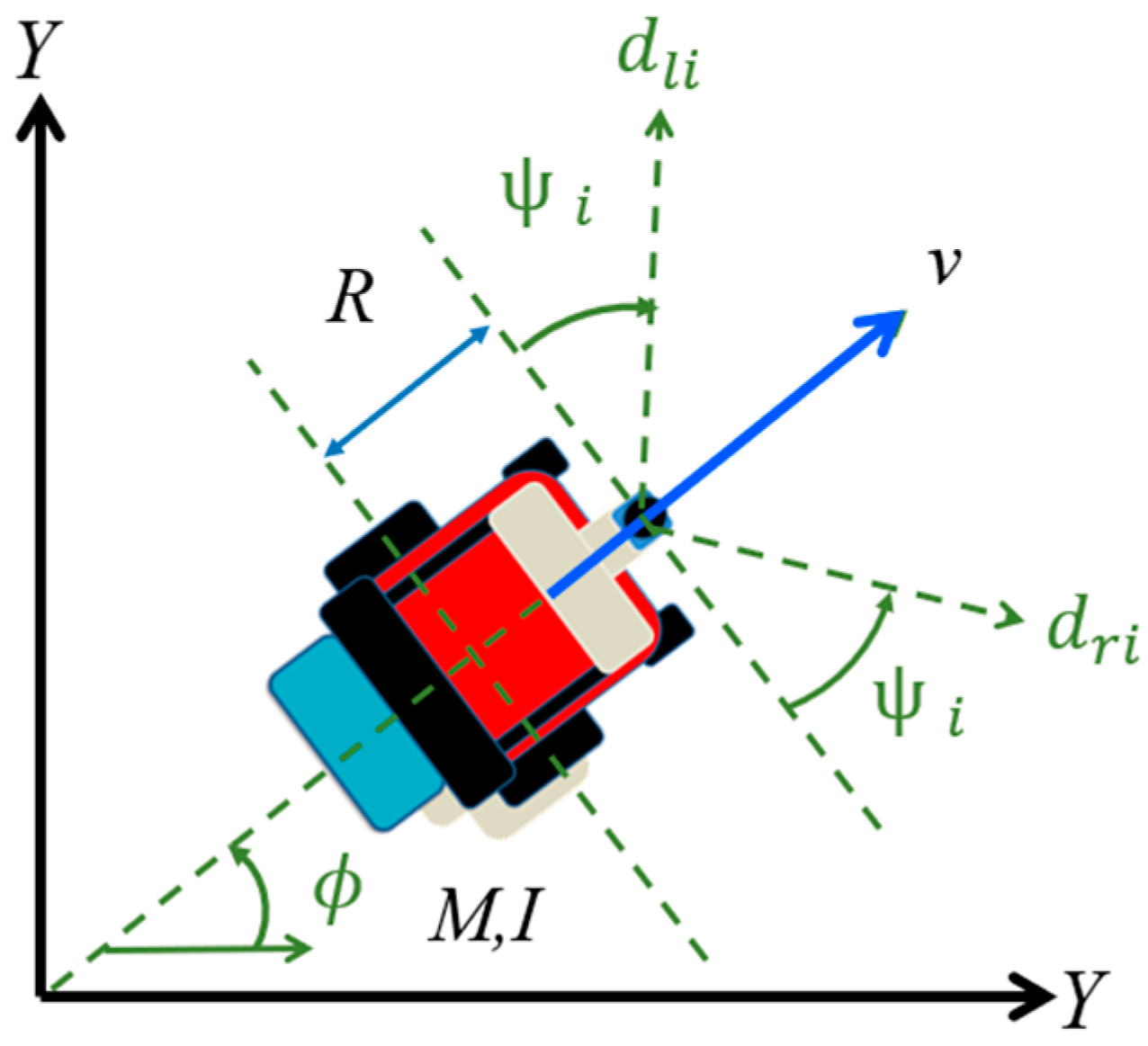
Before designing the obstacle avoidance controller, the incomplete constraints of the robot and the user-controlled inputs for the iE-Wheelchair are investigated. As to the feasibly shared control used in human-robot interaction systems, Figure 2 depicts the proposed obstacle avoidance controller as the reference model control while considering the human control inputs. The motion controlling from the user is turning accelerations ω ˙ u and accelerations v ˙ u with respect to the center of the iE-Wheelchair. On the other hand, the controlling of the robot considers the measurements dri and dli, representing, respectively the distances observed from different angles by the laser range finder. The subscripts r and l denote the sensing distance from the right- and left-half sides of the iE-Wheelchair, respectively, as shown in Figure 3.
Based on the dynamics of a two-wheeled mobile robot model, a simple illustration of iE-Wheelchair employed in our study is shown in Figure 3, where the system model in terms of turning acceleration ϕ ¨ and translational acceleration v ˙ with respect to the laser range finder attached to the front of the iE-Wheelchair, without considering the wheel-slippage, are given as follows:
I ϕ ¨ + C ϕ ϕ ˙ = I ϕ u ¨ h u m a n   c o n t r o l   i n p u t s + i = 1 m α i d r i n i = 1 m α i d l i n r o b o t   c o n t r o l   i n p u t s = I ϕ h ¨ + C ϕ ϕ h ˙ h u m a n   c o n t r o l   i n p u t s + I ϕ r ¨ + C ϕ ϕ r ˙ r o b o t   c o n t r o l   i n p u t s
M v ˙ + C v v = M v u ˙ h u m a n   c o n t r o l   i n p u t s i = 1 m β i d r i n i = 1 m β i d l i n r o b o t   c o n t r o l   i n p u t s = M v h ˙ + C v v h h u m a n   c o n t r o l   i n p u t s + M v r ˙ + C v v r r o b o t   c o n t r o l   i n p u t s
where I and M are angular inertial and mass of the iE-Wheelchair, and the viscous friction coefficients of angular velocity and velocity are C ϕ and C v , respectively. Since there may exist viscous frictions when the wheelchair moves, they are concerned about the system in order to increase the overall stability. In Equation (2), the last two terms on the right-hand side depict the steering effect from the robot control that depends on the sensed distance magnitude d r i and d l i . Similarly, the last two terms on the right-hand side Equation (3) provide the braking effect that depends on the sensed distance magnitude d r i and d l i . Note that the terms I ϕ u ¨ and M v u ˙ present the desired driving force from the human control inputs where ϕ u ¨ = ω ˙ u . The terms I ϕ r ¨ + C ϕ ϕ r ˙ and M v r ˙ + C v v r are the ones yielded from the robot to be able to perform the obstacle-avoidance task. The parameters ϕ h ˙ and v h derived from human control inputs as well as ϕ r ˙ and v r derived from robot control inputs are both used for the design of the shared controller, as introduced in Section 4. In the summation calculation of Equations (2) and (3), m represents half the number of distance observations, while α i and β i are constant parameters that are used to change turning and braking conditions. Finally, the value friction of the term 1 / d j i n (j = r and l) is designed to represent the extent due to the influences from obstacles to turning and braking; that is, the lower value adopted for n raises the higher impact of the relative distances from obstacles to the wheelchair.
Based on the linear model of the control system in Equations (2) and (3), the stability analysis of the obstacle avoidance controller can be accordingly developed. To begin with, this study investigates the motion dynamics of the wheelchair in the moving environment as shown in Figure 4, which consists of curves of walls on the two sides of the path. As for the case in which straight walls appeared on the two sides of the path, this has been analyzed and proposed in [37]. By assuming that the two curves belong to a simple concentric circle with radii R c + r and R c r , respectively, the wheelchair moves along the central path with velocity and angular velocity can be expressed as v = v 0 + v S and ϕ ˙ = ϕ ˙ 0 + ϕ ˙ S , where v 0 and ϕ ˙ 0 are two expected constants while v S and ϕ ˙ S are small variants. According to Equations (2) and (3), it is desired to assume that human control inputs satisfy I ϕ u ¨ = C ϕ ϕ ˙ 0 and M v u ˙ = C v v 0 . Additionally, we assume that the distance between the wheelchair and the center of two curves is r s , which is a small variance, ψ i is the angle between each sensory observation i and the center of the wheels, and the distance between the center of the wheelchair, as well as the laser range finder, is R. As a result, a distance between every sensory observation and the walls can be provided by,
d r i = z r i + z r i 2 r s 2 R c + r s + r 2 R c + r R
d l i = z l i z l i 2 r s 2 R c + r s + r 2 R c + r R
z r i = R c + r s c o s ψ i + ϕ S
z l i = R c + r s c o s ψ i ϕ S
Because r s and ϕ S are small variants, the zero and first derivative of Equations (4) and (5) with respect to r s and ϕ S are linear. Thus, by using Taylor expansion, we can linearize d r i and d l i as,
d r i a i + b i R c i + d i r s + e i f i ϕ S
d l i a i b i ^ R + c i + d ^ i r s + e i f ^ i ϕ S
where
a i = R c c o s ψ i
b i = a i 2 + 2 r R c + r 2
c i = c o s ψ i
d i = R c 1 c o s 2 ψ i / b i
e i = R c s i n ψ i
f i = R c 2 s i n ψ i c o s ψ / b i
b ^ i = a i 2 2 r R c + r 2
d ^ i = R c 1 c o s 2 ψ i / b ^ i
f ^ i = R c 2 s i n ψ i c o s ψ / b ^ i
Since the linearization of 1 / d j i n can also be approximated by using the Taylor series expansion, i.e.,
1 / d j i n = p i d j i + q i
where j = l, r and p i as well as q i are two positive constants. From (8), (9) and (19), Equation (2) considering only the robot control inputs can be rewritten as
I ϕ ¨ + C ϕ ϕ ˙ = i = 1 m α i p i 2 a i b i b ^ i + 2 c i + d i + d ^ i r s f i + f ^ i ϕ S
Similarly, the linearization of Equation (3) considering only the robot control inputs is given as follows:
M v S ˙ + C v v S = i = 1 m β i p i b i b ^ i + d ^ i d i r s + 2 e i + f i f ^ i ϕ S 2 R 2 q i
By assuming that νs and ϕS are small, the derivative of rs is accordingly linearized as shown below.
r s ˙ = v sin ψ S v 0 + v s ϕ S v 0 ϕ S
From Equations (20)–(22), the state-space of the system dynamic equation X ˙ = A X + Φ can therefore be found as follows.
ϕ s ˙ ϕ s ¨ r s ˙ v s ˙ = X ˙ = A X + Φ = A ϕ s ϕ s ˙ r s v s + Φ
where A and Φ are shown below.
A = 0 1 0 0 1 I Σ i = 0 m α i p i f i + f ^ i C ϕ I 1 I Σ i = 0 m α i p i 2 c i + d i + d ^ i 0 v 0 0 0 0 1 M Σ i = 0 m β i p i 2 e i + f i + f ^ i 0 1 M Σ i = 0 m β i p i d i + d ^ i C v v 0 M
Φ = 0 1 I Σ i = 0 m α i p i 2 a i + b i + b ^ i 0 1 M Σ i = 0 m β i ( p i b i b ^ i 2 R 2 q i )
Remark 1. 
Substituting the parameters of (10)–(18) to (25), a constant matrix  Φ  can be achieved. To investigate the stability of the state X, a Lyapunov candidate function  V X = 1 2 X T X  can be chosen. To satisfy the stability in the sense of Lyapunov theory  V ˙ X < 0 , the state X of the linear system  X ˙ = A X + Φ  is uniformly ultimately bounded (UUB) stable if the matrix A is Hurwitz and  X Φ . It is worth mentioning that the bounded value of  Φ  can represent the error bound for the relative distance between the wheelchair and the obstacle. As a result, the nonzero value of  Φ  also provides a buffer zone around the obstacles with regarding to the chosen parameters.
Consequently, to investigate whether the matrix A is Hurwitz, the characteristic real polynomial can be derived as follows:
P s = s I A = s 4 + s 3 h 3 + s 2 h 2 + s h 1 + h 0
where the coefficients h0, h1, h2, and h3 are
h 0 = C v v 0 I M i = 0 m α i p i 2 c i + d i + d ^ i
h 1 = C v I M i = 0 m α i p i f i + f ^ i + h 0 M C v
h 2 = C ϕ C v I M + 1 I i = 0 m α i p i f i + f ^ i
h 3 = C ϕ I + C v M
By using the Liénard-Chipart criterion [38], as long as all of the coefficients of Equation (26) with respect to the Hurwitz matrix of P are positive, then it is regarded as stable. Hence, to achieve the safe operation with the stability guarantees for the obstacle avoidance controller, the following equation must be satisfied:
D = h 3 h 1 0 1 h 2 h 0 0 h 3 h 1 = h 3 h 2 h 1 h 1 h 3 2 h 0 > 0
Substituting the parameters of (10)–(18) to (31), we can obtain
C ϕ f i + f ^ i I v 0 2 c i + d i + d ^ i > 0
Then, after substituting the parameters of (10)–(18) to (32), as long as C ϕ satisfies the above inequality, the system stability of the dynamic equation in (23) can be guaranteed.

4. Design of Adaptive Shared Controller

This section presents the design of the self-adaptive shared controller based on the convex analysis similar to [34,35]. Before introducing the convex set stability analysis, let us define several necessary parameters: u r = [ v r , ω r ] and u h = [ v h , ω h ] are the control inputs from the robot and the human user, respectively; u s = [ v s , ω s ] is the final controlling of the shared controller based on the designed weight α s to tune the ratio between u r as well as u h .

4.1. Convex Set Stability Analysis

Assume that the valid input set from the user is defined as U h , where U h = { u h :   V h ˙ u h < 0 } . The set is then regarded as a convex set because u h U h and the range of the stability are continuous during the operation. Likewise, the valid input set from the robot is defined as U r = { u r :   V r ˙ u r < 0 } where u r U r . The control weight of u s is the point that goes through the closed line between u r and u h , where the closed line can be defined as,
U s = { u s :   u s = α s u r + 1 α s u h   | u s U s ,     0 < α s < 1 }
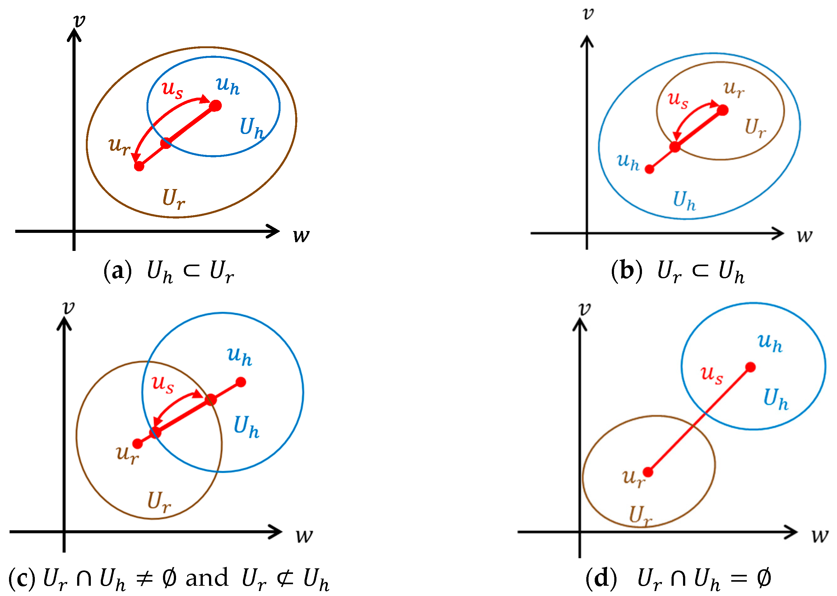
Accordingly, there are four conditions between u r and u h that are preferable for designing and developing the shared controller:
  • As shown in Figure 5a, the state is stable if U h U r because any arbitrary control applied on the iE-Wheelchair is independent of causing collision with obstacles. Hence, the system is reliable and safe. Under such a scenario, α s is assigned to be 0, implying that the system is under is controlled completely by the user.
  • As shown in Figure 5b, the condition where U r U h refers to the situation is when the valid input set from the robot involves the inputs from the user. Therefore, some inputs can be in both sets simultaneously, while others cannot. In actual operations, such a scenario implies that there exist obstacles in the environments and thus the iE-Wheelchair requires manual control to avoid collisions by tuning the value of control weight α s . From the viewpoint of the control theory, U s = U r U s l , and the proper value of α s lies within the inequality α s l < α s < 1, where α s l is the minimum of α s .
  • When the valid input sets of the user and the robot intersect with each other, i.e., U r U h as well as U r U h , as shown in Figure 5c, this scenario is similar to the second condition, but it is more complicated in real environments. The stability range of α s is α s l < α s < α s u , where α s u is the maximum of α s .
  • The instability condition occurs if U r U h = since no intersection appears in both sets, as shown in Figure 5d. In other words, there does not exist a valid control weight such that the iE-Wheelchair can be controlled properly. Such a scenario happens when the wheelchair moves very close to obstacles; therefore, the robot will immediately stop the wheelchair from moving further.

4.2. Algorithm of Deriving the Weight Adaptation

According to the stability analysis of the self-adaptive shared controller, it is required to develop an algorithm that is in charge of computing the proper control weight. The control weights for the user and the robot input (namely, α h and α r , respectively) are determined in accordance with the analysis of the convex model. The designed algorithm is detailed as follows:
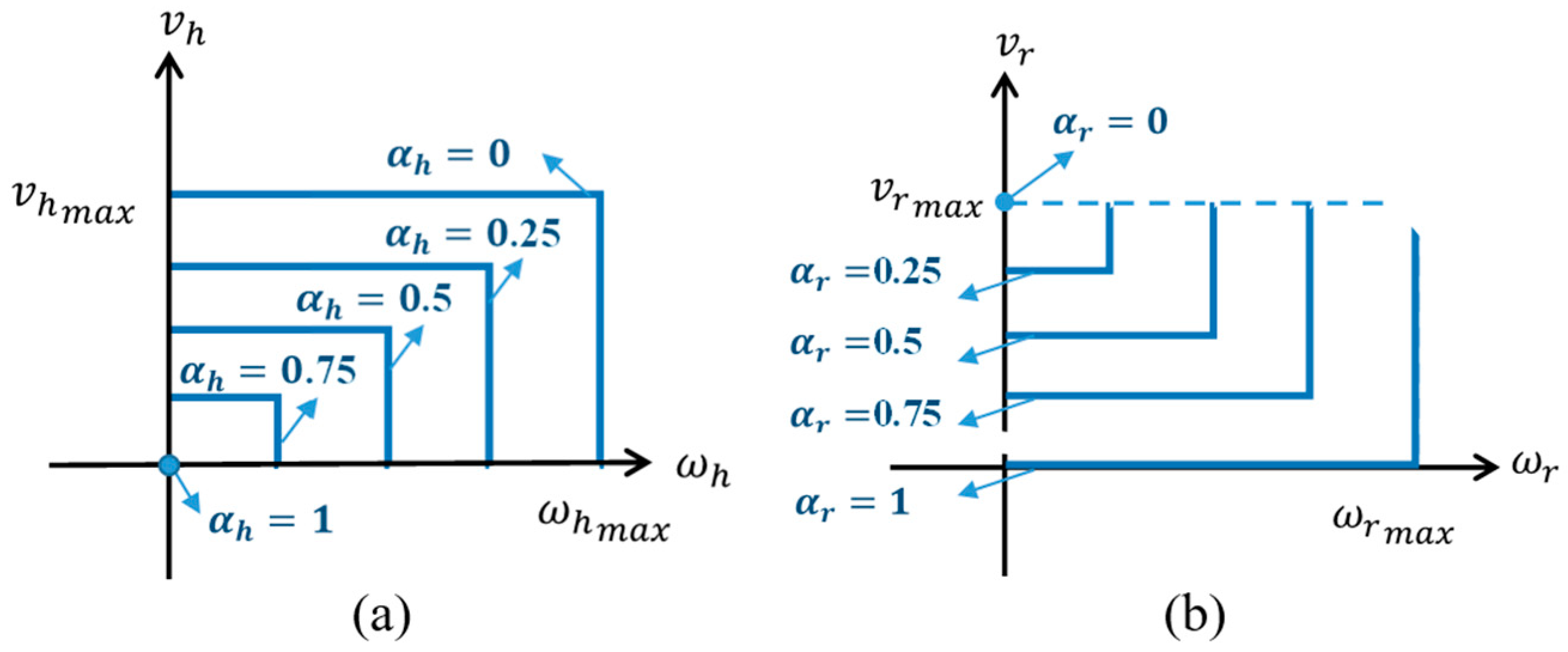
  • Control weight of user-controlled input α h : the most stable status of the iE-Wheelchair is set to stationary without any control from the user. That is, when the velocity for moving straightforward v h and the angular velocity ω h are zero, α h is assigned as 1. The higher the velocity, the more unsafe the system is. Therefore, as soon as the maximum value of v h and ω h are reached, this control weight has to be set as zero. As illustrated in Figure 6a, the control weight is inversely and linearly proportional to the velocity. As a result, α h is defined as follows:
    α h = 1 ν h 2 + ω h 2 v h m a x sin θ h 2 + ω h m a x cos θ h 2
    where
    θ h = tan 1 v h ω h
  • Control weight of the robot control input α r : The most stable state occurs when the velocity of moving straightforward v r and the angular velocity ω r are zero, which implies that no obstacles appear in the surrounding environment of the iE-Wheelchair. In such a scenario, the weight control of the robot is assigned to be zero. On the other hand, when the maximum values of v r and ω r are reached, implying that the obstacle is very closed to the robot, α r has to be 1. Similar to the weight control in the user input, Figure 6b presents the relationship between α r and the velocity as well as the angular velocity, where α r is linearly proportional to ω r while inversely and linearly proportional to v r , respectively. As a result, α r is defined as follows:
    α r = v r m a x ν r 2 + ω r 2 v r m a x sin θ r 2 + ω r m a x cos θ r 2
    where
    θ r = tan 1 v r m a x ν r ω r
Algorithm 1 shows the pseudo-code of the proposed algorithm for deriving the weights adaptation. Steps 3 to 11 present the auto-tuning scheme for the weight α s , where the dichotomy method is used when the valid input set from the robot is included in the one from the user. As for the case when an unstable condition happens, the shared weight yielded to take the input set from the robot more than the one from the user into account. Note that since there is no sensor in the back of the wheeled chair, our system currently is only allowed to move forward, stop, or turn either left or right.
Algorithm 1: Weight adaptation for the Human and the Robot Inputs
Input:
ω h : the rotational velocity of human control.
v h : the translational velocity of human control.
ω r : the rotational velocity of robot control.
v r : the translational velocity of robotic control.
v m a x = v h max , v r max : the robot maximum translational velocity.
ω m a x = ω h max , ω r max : the robot maximum rotational velocity.
α h : the weight of human control given by (35).
α r : the weight of robot control given by (37).
Output:
u s : v s , ω s : v s and ω s are the translational and rotational velocity of the robot
Optimal α s : the weight of shared control.
Main:
1. 
for each step do
2. 
   α h = 1 ν h 2 + ω h 2 v h m a x sin θ h 2 + ω h m a x cos θ h 2 θ h = tan 1 v h ω h α r = v r m a x ν r 2 + ω r 2 v r m a x sin θ r 2 + ω r m a x cos θ r 2 θ r = tan 1 v r m a x ν r ω r
3. 
if ( v h < 0 v r < 0 ) then
4. 
     v s 0 ; ω s 0 ;
5. 
else if ( v h < v r ) & ( ω h < ω r ) & ( ω h ω r > 0 ) then
6. 
     α s 0
7. 
else if ( v h > v r ) & ( ω h > ω r ) & ( ω h ω r > 0 ) then
8. 
     α s 1 + α r 2
9. 
else
10. 
     α s α r α h + α r
11. 
 end if
12. 
end for

4.3. Adaptive Shared Controller Design

To provide a dynamic model of our developed iE-Wheelchair, we integrate the motion model with linear stability as mentioned in Section 3, and the algorithm of auto-tuning the control weight based on the convex analysis as mentioned in Section 4.1. With the extension from Equations (2) and (3), the dynamic model with weight adaptation scheme can be developed as follows:
I ϕ ¨ + C ϕ ϕ ˙ = 1 α s I ϕ ¨ u h u m a n   c o n t r o l   i n p u t s + α s i = 1 m α i d r i n i = 1 m α i d l i n r o b o t   c o n t r o l   i n p u t s
M v ˙ + C v v = 1 α s M v ˙ u h u m a n   c o n t r o l   i n p u t s + α s i = 1 m β i d r i n i = 1 m β i d l i n r o b o t   c o n t r o l   i n p u t s
The block diagram of the proposed self-adaptive shared control system is shown in Figure 7. The reference model takes human and robot inputs to provide expected angular velocity ϕ ˙ h , ϕ ˙ r and the moving velocity v h ,   v r of human and robot control, respectively. Meanwhile, the control weight αs in the adaptive shared controller is adjusted based on the proposed algorithm in Algorithm 1. Subsequently, the adaptive shared controller can generate the referenced angular velocity ϕ ˙ c m d and referenced moving velocity v c m d for driving the iE-Wheelchair with obstacle-avoidance capability while incorporating human user control authority.

5. Experiments

To verify the proposed approach, several experimental environments are designed based on various human errors. Additionally, how the parameters are designed in the proposed approach are addressed. The experimental results are verified by several criteria such as smoothness and fluency as well as required completion time.

5.1. Design of Controller Parameters

Table 1 shows the parameters used in the proposed system, including the mass M, angular inertial I, the distance between the center of the wheelchair and the laser range finder R, halfwidth of the pavement r, expected velocity v0, the radius of the curve Rc, and the viscous frictions coefficient of angular velocity C ϕ . Notice that C ϕ needs to be carefully designed to ensure the stability criterion as mentioned in (32). As for constant parameters such as αi, βi, and viscous frictions coefficient of velocity C v , they are determined to meet the aforementioned stability and performance requirements to the developed iE-Wheelchair system.
There are four different control modes in the experiments: Auto, Manual, Fixed Share, and Adaptive Share. Specifically, except for the adaptive shared control proposed in the conducted experiments, the control weights αs of the other three control modes are designed as 1, 0, and 0.5, respectively. Detailed descriptions of each mode are provided as follows.
  • Auto mode: The whole system is performed autonomously, without any control by the user. Therefore, the iE-Wheelchair only moves forward and makes either left or right turns until the user terminates the system.
  • Manual mode: No obstacle avoidance is provided by the system. Only when the iE-Wheelchair approaches the obstacles too closely does the shared control system immediately activate the emergency braking.
  • Fixed Shared mode: The value of αs is set as the constant 0.5 in the experiments.
  • Adaptive Shared mode: The values of weights are adaptively adjusted according to the environment.

5.2. Experimental Setup

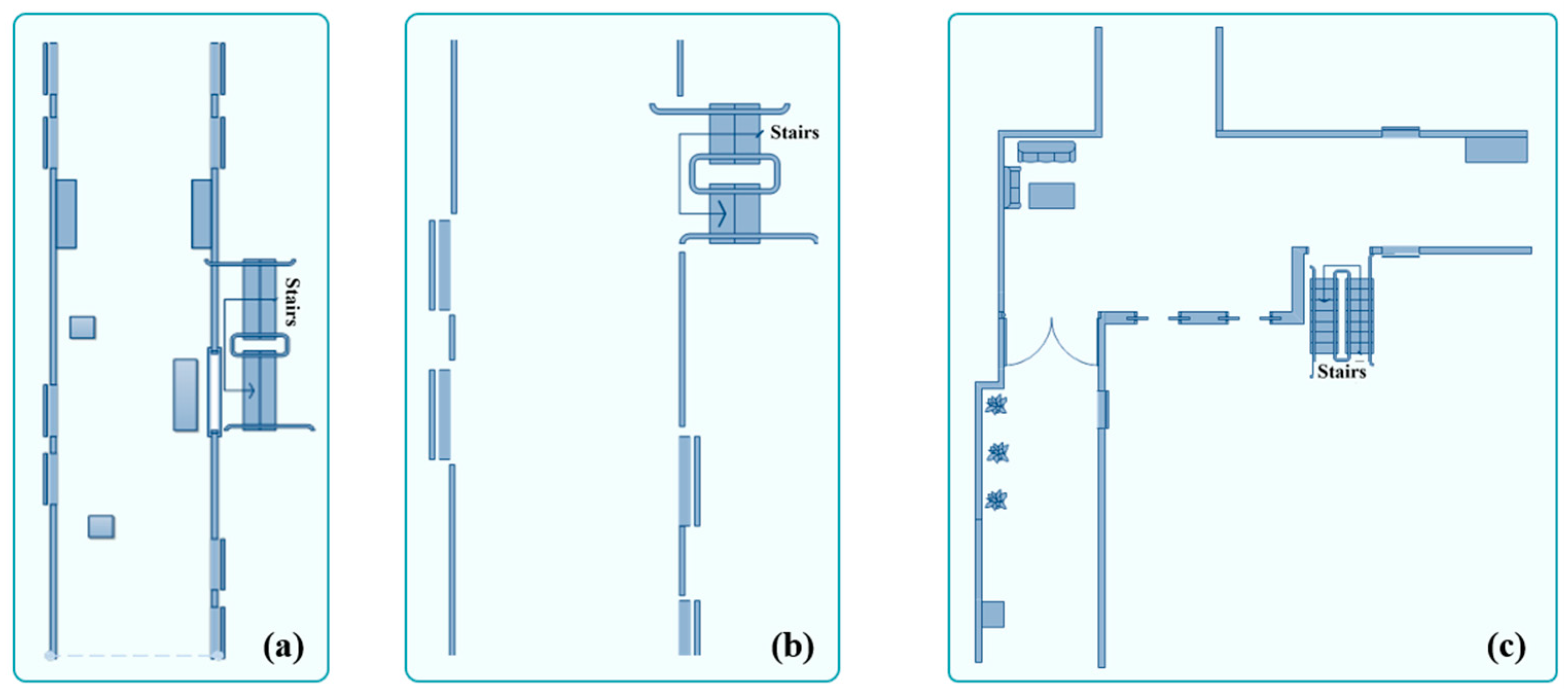
To investigate the performances of the proposed system in scenarios when human errors occur during the control of the iE-Wheelchair, three experimental environments of human errors are designed based on skill-based error, decision error, and speed error.
  • Skill-based error: skill-based error refers to the scenario in which the user is distracting when controlling the iE-Wheelchair. Thus, a delay of the operation control is likely to happen. In our experiments, the time delay is set to be 0.5 s for the manual operation of the user.
  • Decision error: the miscarriage of orientation, regarded as the decision error, could be happened when the user operates the wheelchair towards walls or obstacles. Therefore, decision error is represented as the iE-Wheelchair is controlled by the user to approach the wall or obstacles.
  • Over-speeding error: if the wheelchair is moving at a high speed, the risk of danger increases while causing injuries both for the user and the robot. Thus, it is essential to concern such a scenario in our experiments.
The environments for the three scenarios can be seen from Figure 8a–c, respectively. In Figure 8a, an S-shape path is designed for the iE-Wheelchair to avoid colliding with obstacles that appeared on the corridor. As such, the delay of manipulations by the user can be investigated. As for Figure 8b, the iE-Wheelchair is approaching the left walls to investigate the decision error from the user. Finally, the over-speed iE-Wheelchair is moving along the inverted L-shape corridor shown in Figure 8c.

5.3. Evaluation Criterion

Based on the criterion of [6], smoothness Cs, fluency Cf, and the required time for completing the experiment, Ct are used in the experiments, where Cs and Cf are, respectively, expressed as follows:
C s = 1 T t = 1 T θ t θ t 1 l t 1 + 1 1
C f = 1 T t = 1 T l t l t 1 1
where T is the total amount of time steps, l(t) represents the forward distance from t to t + 1, and θ(t) is the orientation at t. If the orientation is frequently changed, the value of Cs is small. Similarly, if the velocity is frequently changed, the value of Cf is also small. Therefore, the larger the values of Cs and Cf with less required time, Ct, to complete the specific task, the better the control system is.

5.4. Test Results and Analysis

(1) Operation of the iE-Wheelchair with Skill-Based Errors: In this experiment, three boxes are arbitrarily placed on the corridor, and the iE-Wheelchair is only allowed to move in an S-shape path to avoid colliding with those boxes. Four different control modes are investigated when the iE-Wheelchair approaches these obstacles. The experimental results using the four control modes are shown in Figure 9a, in which four colors of trajectories correspond to four control modes, respectively. The Auto mode can provide the smooth moving trajectory while the Manual mode does not control the iE-Wheelchair smoothly. This is because the user has to employ his/her experiences and pay more attention to controlling the iE-Wheelchair to avoid any collision, while the shared control with either fixed or adaptive weights allows the iE-Wheelchair to promptly adjust its own orientation before it gets too close to the obstacles. Accordingly, both the shared control modes are superior to the Manual mode in terms of the smoothness of the trajectory. The changes of weights of adaptive shared control mode are shown in Figure 9b. When the iE-Wheelchair approaches the obstacles (or moves into narrow areas), the weight values of Adaptive Shared mode become higher, implying that the driving action is about to be unsafe, and thus the weights are increased to prevent human mistakes.
It can be observed that the values of the resulting weights in the Adaptive Shared mode are higher than 0.5 as in the Fixed Shared mode, because there exists the time delay 0.5 s from human operation. Therefore, it is obvious to distinguish the results conducted by the shared control with adaptive weights and the fixed weights. Moreover, to compare the performances of the four control modes in terms of the criterion used in [6], the performances of the four control modes in terms of the three criteria are shown in Figure 10a–c, respectively. From the observation in Figure 9a, the moving trajectory driven from the Adaptive Shared mode is similar to the Auto mode. Furthermore, we can see that the Adaptive Shared mode performs superior to others in terms of smoothness Cs and fluency Cf. As for the required time for task completion, Ct, it is also similar to the Auto mode. Hence, when a skill-based error occurs in human operations, the proposed Adaptive Shared mode reveals the most favorable mobility assistance.
(2) Operation of the iE-Wheelchair with Decision Errors: If the user miscarriages the orientation during wheelchair turning, the collision to obstacles is more likely to happen. Thus, in this experiment, the iE-Wheelchair is allowed to move towards the side-wall. The experimental results using the four control modes are shown in Figure 11a, and the changes of weights of the adaptive shared control mode are shown in Figure 11b. Auto mode controls the iE-Wheelchair to move on the central trajectory, independent of the user control since it does not consider the user control input. The Manual mode yields the most shaking trajectory, and as the iE-Wheelchair approaches the side-wall, collision is likely to have occurred. On the other hand, the shared control with either fixed or adaptive weights allows the iE-Wheelchair to move smoothly and safely. From the obvious evidence shown in Figure 11b, as the iE-Wheelchair approaches the side-wall, the weights then increase, which implies that the shared controller dominates and is more controlling than the user to prevent any collision to wall or obstacles. After that, when the iE-Wheelchair moves away from the side-wall, the weights decreases to small due to less risk of collision.
To further investigate the performances of the shared control with fixed weights and adaptive weights, we can see from Figure 12a–c, in which the Adaptive Shared mode yields better smoothness Cs and fluency Cf. The required completion time Ct is just slightly worse than the shared control with fixed weights. It is noticeable that the Auto mode in such a case can be regarded as the standard because it does not consider human errors. Thus, concerning both the human control inputs as well as being controlled by the robot inputs, the Adaptive Shared mode reveals the most favorable operation.
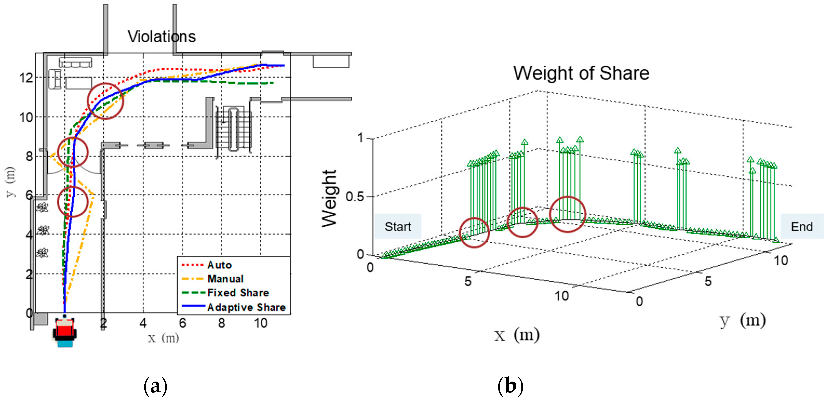
(3) Operation of the iE-Wheelchair with Over-Speeding Errors: In this experiment, the over-speeding wheelchair driving is investigated in an inverted L-shape corridor, as shown in Figure 13a, where the trajectories provided by the four modes are presented. We can see that the Auto mode and the shared control (Fixed and Adaptive Shared mode) perform smooth trajectories, while Manual mode provides the worst result. Besides, Figure 13b is similar to Figure 11b where it can be seen that as the iE-Wheelchair approaches obstacles, the weight of shared control increases. As to the performance evaluation of the four modes according to the three criteria, i.e., smoothness Cs, fluency Cf, and completion time Ct, it can be seen from Figure 14a–c that, apart from the Auto mode, the Adaptive Shared mode provides the better results. However, shared control with a fixed weight, on the other hand, cannot cope with the over-speeding scenario because the weight is constant as 0.5. Therefore, it is only better than the Manual mode. When the iE-Wheelchair is over-speeding, shared control with adaptive weight can balance the safety of the system and the errors that occurred in the manual control. By concerning human errors, the Adaptive Shared mode thus performs a favorable result.
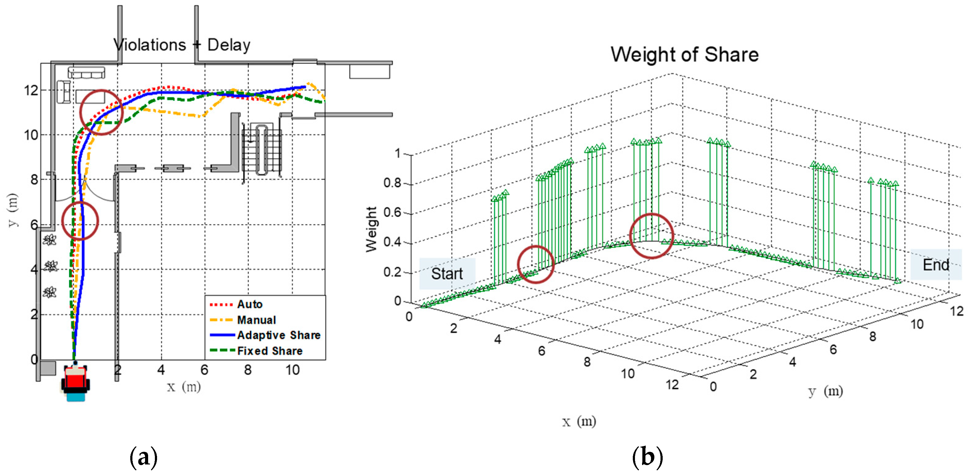
Aside from solely the over-speeding, the final experiment further investigates the over-speeding error together with skill-based error (0.5 s time delay for manual operation). The resultant trajectories of the four control modes are shown in Figure 15a, and the changes of weight in the adaptive shared control are presented in Figure 15b. Note that when skill-based error and over-speeding error happens at the same time, it causes high risk for the iE-Wheelchair to collide with obstacles, leading itself to hazardous situations. Thus, the values of weights in the adaptive shared control vary dramatically so that smoothness and safety in controlling performance can be achieved simultaneously, as can be seen from Figure 15b. The performance evaluations of the four control modes in such a scenario can be found in Figure 16a–c. Similar to the over-speeding error experiment, the shared control with fixed weight cannot immediately react to the environments such as moving through the narrow corridor. As a result, it does not perform the same satisfactory results as the Adaptive Shared mode, which provides excellent performances in terms of the yielded three criteria, i.e., smoothness Cs, fluency Cf, and completion time Ct.
According to the above experiments, we can summarize the performances of the four modes as follows:
  • Shared control with fixed weights gives better results over adaptive shared control when the iE-Wheelchair is controlled normally.
  • However, when considering human errors, the proposed method has shown the effectiveness in terms of improving smoothness, fluency, and completion time, and also reducing user driving load while ensuring the stable and safe operation of the iE-Wheelchair.

6. Conclusions

In this study, an adaptive shared control strategy is proposed and implemented into an intelligent wheelchair system while considering human error protection. To respect the control ability of the user while keeping the stable and safe human–robot interaction, the domination over the wheelchair mobility is adjusted according to the sensory observation of a laser range finder. The safety operation of the shared control system is guaranteed by the stability analysis using the linearized reference model and the Liénard-Chipart criterion. As such, the essential criteria for the design of an obstacle avoidance controller can be developed. Subsequently, based on convex analysis and set theory, the stability and performance of the adaptive shared controller can be analyzed to find the adaptive weight for suitable human–robot cooperation in real-time navigation. To verify the proposed system, three sets of human error experiments are used, including skill-based error, decision error, and speed error. In terms of the three criteria including smoothness, fluency, and required completion time of specific tasks, the experimental results show that the proposed iE-Wheelchair not only effectively guarantees the safe operation for the user, but also provides stable control behavior with smoothness and fluency.
Finally, it is worth mentioning that the distance measurements play important roles to determine the shared controlling effectiveness of our proposed approach. The distance information can also be provided from other distance measuring sensors such as ultrasonic sensors. However, to provide the same detection range in a horizontal field, we may need several ultrasonic sensors located around the iE-Wheelchair. The different effect to our approach while considering distance sensor characteristics can be left for future works.

Author Contributions

Conceptualization, H.-H.C.; Data curation, W.-T.Y.; Formal analysis, W.-T.Y.; Funding acquisition, H.-H.C. and J.-S.L.; Investigation, H.-H.C. and J.-S.L.; Methodology, H.-H.C. and W.-T.Y.; Project administration, J.-S.L.; Software, W.-T.Y.; Supervision, H.-H.C. and J.-S.L.; Validation, H.-H.C., W.-T.Y. and J.-S.L.; Visualization, W.-T.Y.; Writing—original draft preparation, W.-T.Y.; Writing—review and editing, H.-H.C. and J.-S.L. All authors have read and agreed to the published version of the manuscript.

Funding

This research is sponsored by the National Science and Technology Council, Taiwan, under Grants No. MOST 111-2221-E-027-147-MY2 and NSTC 111-2218-E-027-005.

Data Availability Statement

Not applicable.

Conflicts of Interest

The authors declare no conflict of interest.

References

  1. Liu, H.-D.; Gao, G.-J.; Lu, S.-D.; Hung, Y.-H. A novel LCOT control strategy for self-driving electric mobile robots. Energies 2022, 15, 9178. [Google Scholar] [CrossRef]
  2. Mihailidis, A.; Elinas, P.; Boger, J.; Hoey, J. An intelligent powered wheelchair to enable mobility of cognitively impaired older adults: An anticollision system. IEEE Trans. Neural Syst. Rehabil. 2007, 15, 136–143. [Google Scholar] [CrossRef] [PubMed]
  3. Pacchierotti, C. Cutaneous Haptic Feedback in Robotic Teleoperation; Springer: Berlin/Heidelberg, Germany, 2015. [Google Scholar]
  4. Jiang, S.-Y.; Lin, C.-Y.; Huang, K.-T.; Song, K.-T. Shared control design of a walking-assistant robot. IEEE Trans. Control Syst. Technol. 2017, 25, 2143–2150. [Google Scholar] [CrossRef]
  5. Janabi-Sharifi, F.; Hassanzadeh, I. Experimental analysis of mobile-robot teleoperation via shared impedance control. IEEE Trans. Syst. Man Cybern. Part B Cybern. 2011, 41, 591–606. [Google Scholar] [CrossRef] [PubMed]
  6. Faria, B.M.; Reis, L.P.; Lau, N. Adapted control methods for cerebral palsy users of an intelligent wheelchair. J. Intell. Robot. Syst. 2015, 77, 299–312. [Google Scholar] [CrossRef] [Green Version]
  7. Uratsuji, Y.; Takemurab, K.; Takamatsua, J.; Ogasawaraa, T. Mobility assistance system for an electric wheelchair using annotated maps. Adv. Robot. 2015, 29, 481–491. [Google Scholar] [CrossRef]
  8. Khademian, B.; Hashtrudi-Zaad, K. Dual-user teleoperation systems: New multilateral shared control architecture and kinesthetic performance measures. IEEE/ASME Trans. Mechatron. 2012, 17, 895–906. [Google Scholar] [CrossRef]
  9. Powell, D.; O’Malley, M. The task-dependent efficacy of shared control haptic guidance paradigms. IEEE Trans. Haptics 2012, 5, 208–219. [Google Scholar] [CrossRef]
  10. Song, K.T.; Jiang, S.Y.; Lin, M.H. Interactive teleoperation of a mobile manipulator using a shared-control approach. IEEE Trans. Hum. Mach. Syst. 2016, 46, 834–845. [Google Scholar] [CrossRef]
  11. Ezeh, C.; Trautman, P.; Devigne, L.; Bureau, V.; Babel, M.; Carlson, T. Probabilistic vs linear blending approaches to shared control for wheelchair driving. In Proceedings of the International Conference on Rehabilitation Robotics, London, UK, 17–20 July 2017; pp. 835–840. [Google Scholar]
  12. Hansson, A.; Servin, M. Semi-autonomous shared control of large-scale manipulator arms. Control Eng. Pract. 2010, 18, 1069–1076. [Google Scholar] [CrossRef]
  13. Urdiales, C.; Espejo, B.F.; Annicchiaricco, R.; Sandoval, F. Biometrically modulated collaborative control for an assistive wheelchair. IEEE Trans. Neural Syst. Rehabil. Eng. 2010, 18, 398–408. [Google Scholar] [CrossRef] [PubMed]
  14. Li, Q.; Chen, W.; Wang, J. Dynamic shared control for human-wheelchair cooperation. In Proceedings of the 2011 IEEE International Conference on Robotics and Automation, Shanghai, China, 9–13 May 2011; pp. 4278–4283. [Google Scholar]
  15. Urdiales, C.; Peula, J.M.; Fdez-Carmona, M.; Barrué, C.; Pérez, E.J.; Sánchez-Tato, I.; Toro, J.C.; Galluppi, F.; Cortés, U.; Annichiaricco, R.; et al. A new multi-criteria optimization strategy for shared control in wheelchair assisted navigation. Auton. Robots 2010, 30, 179–197. [Google Scholar] [CrossRef]
  16. Ton, C.; Kan, Z.; Mehta, S. Obstacle avoidance control of a human-in-the-loop mobile robot system using harmonic potential fields. Robotica 2018, 36, 463–483. [Google Scholar] [CrossRef]
  17. Xu, Q.; Ge, S. Adaptive control of human-interacted mobile robots with velocity constraint. In Proceedings of the 2018 International Conference on Social Robotics, Qingdao, China, 28–30 November 2018; pp. 390–399. [Google Scholar]
  18. Devigne, L.; Narayanan, V.-K.; Pasteau, F.; Babel, M. Low complex sensor-based shared control for power wheelchair navigation. In Proceedings of the 2016 IEEE/RSJ International Conference on Intelligent Robots and Systems, Daejeon, Republic of Korea, 9–14 October 2016; pp. 5434–5439. [Google Scholar]
  19. Devigne, L.; Pasteau, F.; Carlson, T.; Babel, M. A shared control solution for safe assisted power wheelchair navigation in an environment consisting of negative obstacles: A proof of concept. In Proceedings of the 2019 IEEE International Conference on Systems, Man, and Cybernetics, Bari, Italy, 6–9 October 2019; pp. 1043–1048. [Google Scholar]
  20. Ezeh, C.; Trautman, P.; Holloway, C.; Carlson, T. Comparing shared control approaches for alternative interfaces: A wheelchair simulator experiment. In Proceedings of the 2017 IEEE International Conference on Systems, Man, and Cybernetics, Banff, AB, Canada, 5–8 October 2017; pp. 93–98. [Google Scholar]
  21. Leaman, J.; La, H.-M. A Comprehensive Review of Smart Wheelchairs: Past, Present, and Future. IEEE Trans. Hum. Mach. Syst. 2017, 47, 486–489. [Google Scholar] [CrossRef] [Green Version]
  22. Kucukyilmaz, A.; Demiris, Y. Learning shared control by demonstration for personalized wheelchair assistance. IEEE Trans. Haptics 2018, 11, 431–442. [Google Scholar] [CrossRef] [PubMed]
  23. Soh, H.; Demiris, Y. Learning Assistance by demonstration: Smart mobility with shared control and paired haptic controllers. J. Hum. Robot. Interact. 2015, 4, 76–100. [Google Scholar] [CrossRef]
  24. Devigne, L.; Aggravi, M.; Bivaud, M.; Balix, N.; Teodorescu, S.; Carlson, T.; Spreters, T.; Pacchierotti, C.; Babel, M. Power wheelchair navigation assistance using wearable vibrotactile haptics. IEEE Trans. Haptics 2020, 1, 52–58. [Google Scholar] [CrossRef] [Green Version]
  25. Sheikh Sadi, M.; Alotaibi, M.; Islam, R.; Islam, S.; Alhmiedat, T.; Bassfar, Z. Finger-gesture controlled wheelchair with enabling IoT. Sensors 2022, 22, 8716. [Google Scholar] [CrossRef]
  26. Li, Z.; Zhao, S.; Duan, J.; Su, C.-Y.; Zhao, X. Human cooperative wheelchair with brain-machine interaction based on shared control strategy. IEEE/ASME Trans. Mechatron. 2016, 22, 185–195. [Google Scholar] [CrossRef]
  27. Yang, C.; Wu, H.; Li, Z.; He, W.; Wang, N.; Su, C.-Y. Mind control of a robotic arm with visual fusion technology. IEEE Trans. Ind. Inform. 2017, 14, 3822–3830. [Google Scholar] [CrossRef]
  28. Erdogan, A.; Argall, B.-D. Prediction of user preference over shared-control paradigms for a robotic wheelchair. In Proceedings of the 2017 International Conference on Rehabilitation Robotics, London, UK, 17–20 July 2017; pp. 1106–1111. [Google Scholar]
  29. Broad, A.; Murphey, T.; Argall, B. Highly parallelized data-driven MPC for minimal intervention shared control. arXiv 2019, arXiv:1906.02318. [Google Scholar]
  30. Erlien, S.-M.; Fujita, S.; Gerdes, J.-C. Shared steering control using safe envelopes for obstacle avoidance and vehicle stability. IEEE Trans. Intell. Transp. Syst. 2015, 17, 441–451. [Google Scholar] [CrossRef]
  31. Jiang, J.; Astolfi, A. State and output-feedback shared-control for a class of linear constrained systems. IEEE Trans. Autom. Control 2015, 61, 3209–3214. [Google Scholar] [CrossRef] [Green Version]
  32. Jiang, J.; Di Franco, P.; Astolfi, A. Shared control for the kinematic and dynamic models of a mobile robot. IEEE Trans. Control Syst. Technol. 2016, 24, 2112–2124. [Google Scholar] [CrossRef] [Green Version]
  33. Jiang, C.; Ni, B.; Han, X.; Tao, Y. Non-probabilistic convex model process: A new method of time-variant uncertainty analysis and its application to structural dynamic reliability problems. Comput. Methods Appl. Mech. Eng. 2014, 268, 656–676. [Google Scholar] [CrossRef]
  34. Wang, L.; Wang, X.; Xu, D.; Zhang, X. Non-probabilistic time-variant reliability assessment (NTRA) for the active control of vibration systems with convex uncertainties. ISA Trans. 2018, 83, 276–289. [Google Scholar] [CrossRef] [PubMed]
  35. Wang, H.; Liu, X.P. Adaptive shared control for a novel mobile assistive robot. IEEE/ASME Trans. Mechatron. 2014, 19, 1725–1736. [Google Scholar] [CrossRef]
  36. FAA. Human Factors Analysis and Classification System; Federal Aviation Administration: Washington, DC, USA, 2000.
  37. Uchiyama, N.; Hashimoto, T.; Sano, S.; Takagi, S. Model-reference control approach to obstacle avoidance for a human-operated mobile robot. IEEE Trans. Ind. Electron. 2009, 56, 3892–3896. [Google Scholar] [CrossRef]
  38. Gantmacher, F.R. The Theory of Matrices; Chelsea Publishing Company: New York, NY, USA, 1959; Volume 2. [Google Scholar]
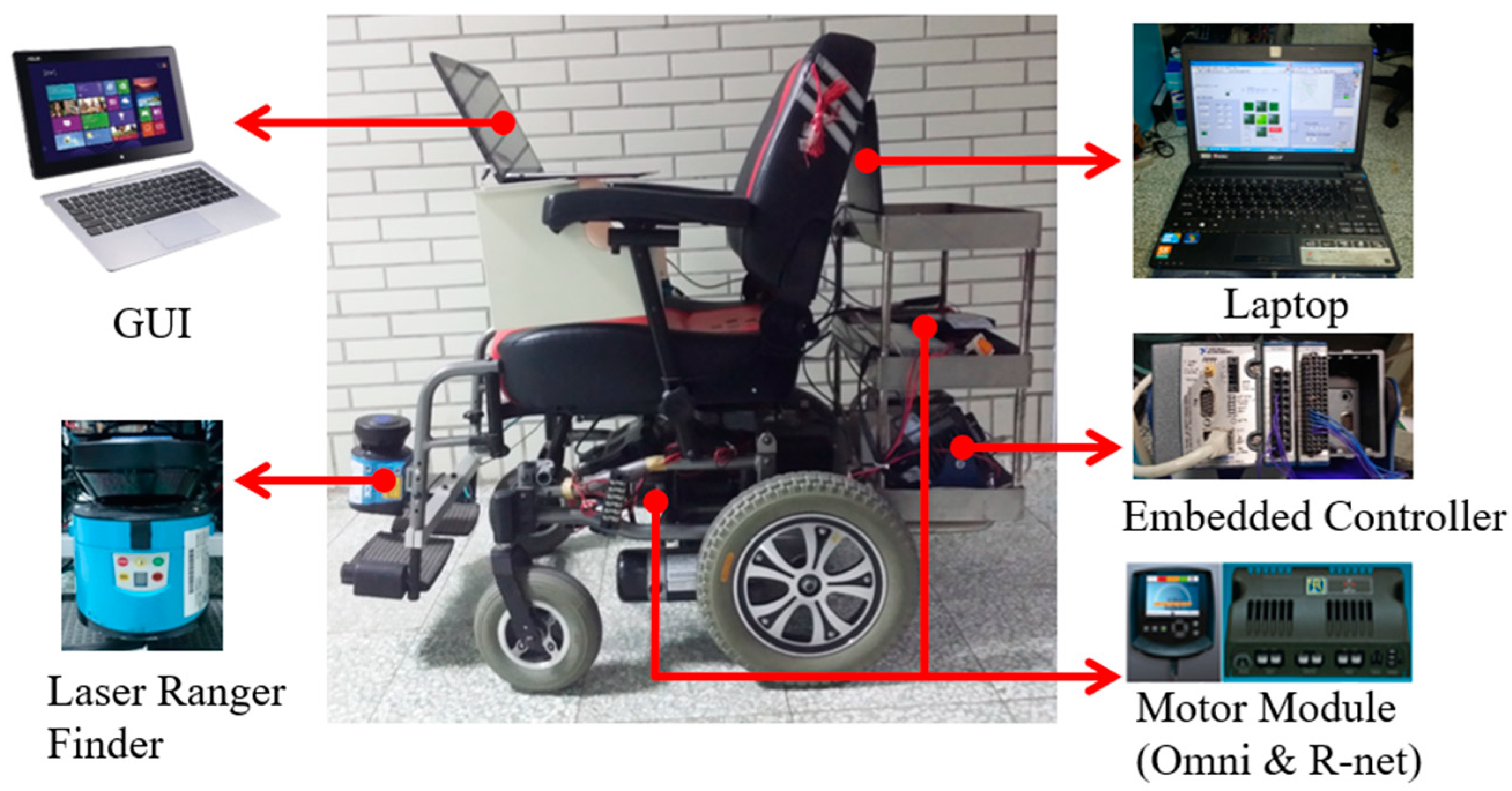
Figure 1. The utilized hardware components for iE-Wheelchair.
Energies 16 02583 g001
Figure 2. The block diagram of the reference model control for the developed iE-Wheelchair.
Energies 16 02583 g002
Figure 3. A cartoon representation of our iE-Wheelchair with the differential-drive kinematics.
Energies 16 02583 g003
Figure 4. Variables used in the motion dynamics of iE-Wheelchair.
Energies 16 02583 g004
Figure 5. Illustration of the convex set stability analysis for wheelchair motion controlling between the robot and human user.
Energies 16 02583 g005
Figure 6. Illustrations of the determination of control weight of human user and robot inputs. (a) Control weight of human user input. (b) Control weight of the robot input.
Energies 16 02583 g006
Figure 7. Block diagram of the proposed adaptive shared control system in the iE-Wheelchair.
Energies 16 02583 g007
Figure 8. Experimental environments of the three scenarios considering different kinds of human errors. (a) S-shape path, (b) Corridor with walls, (c) L-shape corridor.
Energies 16 02583 g008
Figure 9. Experimental results of the skill-based error operation. (a) The trajectories of the four control modes. (b) Changes of the weights of adaptive shared control.
Energies 16 02583 g009
Figure 10. Experimental results of the skill-based error operation in terms of the three criteria. (a) Smoothness (b) Fluency, (c) Completion time.
Energies 16 02583 g010
Figure 11. Experimental results of the decision error operation. (a) The trajectories of the four control modes. (b) Changes of the weights of adaptive shared control.
Energies 16 02583 g011
Figure 12. Experimental results of the decision error operation in terms of the three criteria. (a) Smoothness (b) Fluency, (c) Completion time.
Energies 16 02583 g012
Figure 13. Experimental results of over-speeding operation. (a) The trajectories of the four control modes. (b) Changes in the weights of adaptive shared control.
Energies 16 02583 g013
Figure 14. Experimental results of over-speeding operation using four control modes in terms of the three criteria. (a) Smoothness (b) Fluency, (c) Completion time.
Energies 16 02583 g014
Figure 15. Experimental results of over-speeding operation plus with the skill-based error. (a) The trajectories of the four control modes. (b) Changes in the weights of adaptive shared control.
Energies 16 02583 g015
Figure 16. Experimental results of over-speeding control with skill-based error using four control modes in terms of the three criteria. (a) Smoothness (b) Fluency, (c) Completion time.
Energies 16 02583 g016
Table 1. Parameters designed in the proposed iE-Wheelchair system.
M165 [kg]I49.91 [kg∙m2]
ν01.67 [m/s]R0.55 [m]
Rc0.75 [m]r0.6 [m]
αi2000βi160
Cν450 [Nm/s]Cϕ[Nm/(rad/s)]
Disclaimer/Publisher’s Note: The statements, opinions and data contained in all publications are solely those of the individual author(s) and contributor(s) and not of MDPI and/or the editor(s). MDPI and/or the editor(s) disclaim responsibility for any injury to people or property resulting from any ideas, methods, instructions or products referred to in the content.