Article

Autonomous Electric-Vehicle Control Using Speed Planning Algorithm and Back-Stepping Approach

by
Sofiane Bacha
1,
Ramzi Saadi
1,2,*,
Mohamed Yacine Ayad
3,
Mohamed Sahraoui
1,2,
Khaled Laadjal
2,* and
Antonio J. Marques Cardoso
2,*
1
MSE Laboratory, Department of Electrical Engineering, Mohamed Khider University, Biskra 7000, Algeria
2
CISE—Electromechatronic Systems Research Centre, University of Beira Interior, Calçada Fonte do Lameiro, P-6201-001 Covilhã, Portugal
3
Industrial Hybrid Vehicle Applications, 75000 Paris, France
*
Authors to whom correspondence should be addressed.
Energies 2023, 16(5), 2459; https://doi.org/10.3390/en16052459
Submission received: 2 February 2023 / Revised: 25 February 2023 / Accepted: 2 March 2023 / Published: 4 March 2023
(This article belongs to the Special Issue Advances in the Field of Electrical Machines and Drives 2022)

Abstract

:
Autonomous electric vehicles (AEVs) have garnered increasing attention in recent years as they hold significant promise for transforming the transportation sector. However, despite advances in the field, effective vehicle drive control remains a critical challenge that must be addressed to realize the full potential of AEVs. This study presents a novel approach to AEV drive control for concurrently generating a suitable speed profile and controlling the vehicle drive speed along a planned path that takes into account various driving circumstances that mimic real-world driving. The designed strategy is divided into two parts: The first part presents a proposed speed planning algorithm (SPA) that works on developing an adequate speed profile for vehicle navigation; first, the algorithm uses an approach for identifying sharp curves on the predefined trajectory; secondly, based on the dynamic properties of these curves, it generates an appropriate speed profile to ensure smooth vehicle travel across the entire trajectory with varying velocities. The second part proposes a new back-stepping control technique with a space vector modulation (SVM) strategy to control the speed of an induction motor (IM) as a traction part of the AEV. A load torque observer has been designed to enhance the speed-tracking task, while the system stability has been proven using Lyapunov theory. Through a series of experiments and simulations using MATLAB/Simulink software and the dSPACE 1104 real-time interface, we demonstrate the effectiveness of the SPA combined with the back-stepping control technique and highlight its potential to advance the field of AEV technology. Our findings have important implications for the design and implementation of AEVs and provide a foundation for future research in this exciting area of study.

1. Introduction

In the last two decades, the AEV motorization control field has become a major axis of research, especially with the big trend in the automotive industry toward electric vehicles that use nonpolluting energy sources with zero gas emissions [1,2]. Electric vehicles now include cars, transportation buses, trucks of all sizes, and even agricultural tractors that are at least partially powered by electricity. In comparison to vehicles powered by internal combustion engines, electric vehicles are more environmentally friendly, have highly efficient control motors, which reduce the maintenance cost, and give better performance due to their highly regulated torque and fast acceleration [3,4].
Achieving optimal performance for AEVs requires a robust control technique that can efficiently manage speed tracking and energy consumption while navigating a given trajectory. To accomplish this, accurately predicting the speed profile for a given trajectory is a crucial prerequisite that must be addressed. By developing advanced speed prediction models, we can help ensure that AEVs can navigate trajectories with a high degree of precision, maintain good speed tracking, and minimize energy consumption. This, in turn, will help to increase the efficiency of the AEV technology, paving the way for a more sustainable future in which we can rely on these vehicles to meet our transportation needs.
Over-speeding is a major contributor to crashes on curved roads. To ensure a vehicle remains stable and avoids lateral instability issues such as sideslip and rollovers, there should be an intelligent speed adaption (ISA) to respect the speed limits and maintain the curves [5,6]. However, speed limit signs are nonadjustable and may not always accurately indicate the recommended speed for navigating curves. The growth of intelligent transportation systems (ITSs) has presented new solutions for the problem of navigating curves. One of these solutions is the vehicle-mounted curve speed warning (CSW) system, which aims to increase warning accuracy [7,8]. The CSW system uses various curve speed models to determine if a vehicle is approaching a curve too quickly. Nevertheless, for accurate speed regulation, it is crucial to take into account several other factors, among which the road geometry is one of the most significant. Several studies have been conducted to determine the curve speed model from various perspectives. One of the key perspectives considered is the road surface conditions, which can impact the vehicle’s ability to maintain stability during curve negotiation. In addition, road geometry features, such as the radius of the curve and the super elevation, can also significantly affect the speed required for a vehicle to safely navigate the curve [9,10]. While curve speed estimation has been a topic of discussion in numerous studies, only a limited number of them have been put into practice and assessed in either simulated or real-life settings.
The traction system is a crucial component of electric vehicles, and a careful selection of electric motor types is necessary to drive the vehicle efficiently and maintain high tracking performance. The four main types of motors used in electric vehicles are induction motors (IMs), switched reluctance motors (SRMs), brushless DC motors, and permanent magnet synchronous motors (PMSMs). Therefore, for optimum traction system performance, a thorough understanding of the various electric motor types and their main characteristics is necessary, which can lead to a suitable choice for the electric vehicle application. The IM has emerged as the preferred choice for electric vehicle manufacturers due to several advantages. Firstly, it is a simple design that consists of fewer parts, which translates into easy maintenance and low-cost repairs. Secondly, IMs have proven to be robust and reliable, which is vital in the context of electric vehicles, where high levels of efficiency are required. Additionally, IMs can operate at a wide range of speeds, making them suitable for various driving conditions. Moreover, IMs are highly efficient and do not require any rare-earth metals, making them a cost-effective option. As a result, IMs are widely used in electric vehicles today and are expected to continue to dominate the market for the foreseeable future [11,12,13].
Various control techniques have been developed to enhance the performance of IMs in electric vehicles, with the two primary methods being field-oriented control (FOC) and direct torque control (DTC) [14]. FOC is a method that provides high dynamic speed accuracy, improved torque response, and short-term overload capability. However, this technique has some limitations, such as high computational costs and the need for precise identification of motor parameters [15]. On the other hand, DTC has several advantages over FOC, including a simple structure, less dependence on motor parameters, and no need for current regulation [16]. Nevertheless, the classical DTC technique has some drawbacks, such as difficulty in control at low speeds, high torque and flux ripples, and acoustical noise, due to the use of a hysteresis controller with a switching look-up table [17,18]. Despite these limitations, recent research has focused on enhancing the DTC technique, such as using the SVM strategy to improve its performance at low speeds and reduce torque and flux ripples [19,20]. According to a study conducted in [21], a comparison between FOC and DTC control of an IM showed that the DTC method outperformed FOC in terms of improving the accuracy of reference speed traction and enhancing energy consumption for electric vehicle applications.
This paper proposes a novel approach that significantly enhances the performance of speed control for AEVs compared to existing approaches in the literature. The proposed approach combines an SPA with a back-stepping control technique to achieve highly accurate and robust speed control. The SPA proposed in this paper consists of several key steps. The first step involves detecting the presence of sharp curves in the predetermined trajectory. Geometric information is then utilized to extract the main characteristics of each curve, which are used in combination with the friction coefficient and super-elevation angle to calculate the ideal speed for each curve. By taking into account the trajectory speed limits and acceleration boundaries, an optimal speed profile is generated for the entire trajectory. The proposed control strategy for an AEV induction motor aims to effectively follow the reference speed profile while maintaining fast, dynamic, and robust control with minimal ripple. To achieve this goal, a novel back-stepping controller with an SVM strategy was introduced. This approach involves dividing the entire system into four separate control loops, each with its own control law. The two outer loops contain speed and rotor flux control laws that serve as reference points for the two inner loops, which determine the control law of the entire system. To enhance the robustness of the control loops, a back-stepping load torque estimator was designed to determine the applied load torque and reduce system uncertainties. This estimator also plays a crucial role in reducing the effects of disturbances. The stability of the back-stepping controller is guaranteed by a Lyapunov candidate.
The organization of the rest of the paper is as follows: Section 2 describes AEV velocity planning by using a proposed SPA to obtain an optimal speed profile. Section 3 presents the design of a back-stepping controller using an IM model, SVM strategy, and load-torque estimation to control the speed of the AEV drive. Section 4 details the performance analysis of the designed control technique through simulation and experimental validation by using MATLAB/Simulink software and dSPACE 1104 real-time interface. The last section contains our conclusions.

2. Related Works

Our research is centered around developing efficient control mechanisms for autonomous electric vehicles. Specifically, we are exploring the use of speed planning algorithms to generate an adequate speed profile and a back-stepping control technique to control the vehicle’s velocity. To achieve this goal, we reviewed the existing literature and studies that focus on these two critical aspects.

2.1. Speed Profile Generation

The AEV needs a robust control technique to achieve high performance, good speed tracking, and low energy consumption during its navigation through the trajectory. Therefore, a significant prediction of the speed profile for a given trajectory is a crucial prerequisite for accurate speed control. Solea and Nunes [22] proposed a velocity planning algorithm by dividing the whole trajectory into small parts. Then, a velocity set-point is generated by calculating the appropriate time for each part, ensuring low acceleration and jerk while maintaining a high level of passenger comfort. Previous research has endeavored to establish a model for determining curve speed by exploring multiple factors, including road surface conditions and geometry features [9,10,23,24,25]. These studies utilized the key characteristics of curves to calculate the optimal speed of the vehicle. By taking into account a range of variables, such as the curvature of the road and surface friction, researchers have strived to develop more accurate models for predicting vehicle behavior on curved roads. Nonetheless, to ensure accurate speed regulation, it is important to take other factors into account, such as speed limits and acceleration boundaries. Numerous studies have implemented a driver factor derived from driving tests conducted by a diverse range of drivers on an urban circuit [26,27,28]. By integrating this driver factor with existing vehicle-road interaction models, these studies have significantly enhanced our understanding of driver behavior on curved roads. With the incorporation of the driver’s preferred speed, the model is capable of accurately simulating real-world scenarios and predicting vehicle dynamics with greater precision. However, driver behavior can be highly unpredictable and inconsistent, which could cause issues when it comes to developing autonomous vehicles. In previous studies [29,30,31], machine learning algorithms were utilized to predict the required speed profile for a defined trajectory based on traffic information obtained from real-world data that represents urban transportation scenarios. These approaches offer promising results in terms of accuracy and effectiveness in predicting the required speed profile for a given trajectory. However, one of the main drawbacks of these algorithms is their high computational cost, which can be a significant challenge for real-time applications. The high computational cost of these algorithms can be attributed to the large amount of data processing and analysis required to make accurate predictions.

2.2. IM Speed Control

For the AEV induction motor control, intelligent algorithms were widely used in the IM control field. These algorithms, renowned for their exceptional speed response, high efficiency, and resilience to parameter variation, have proved to be instrumental in ensuring optimum performance of the AEV induction motor. Of these algorithms, neural network and fuzzy logic control [32,33] have emerged as the leading contenders. Despite their remarkable advantages, however, these techniques have their limitations. Their intricate structure and dependence on prior knowledge and expertise make them less suitable for applications that require a simple, user-friendly approach. Model predictive control has emerged as a promising technique in the electric drive and power electronics fields, thanks to its ability to enhance current quality, reduce torque ripples, and improve disturbance rejection. This advanced control method achieves these benefits by generating an optimal switching state in a sampling period to minimize the cost function [13,14,34,35]. Despite its numerous advantages, model predictive control is not without its limitations. One of the main drawbacks of this technique is the high computational demand required to predict the system’s behavior accurately. Additionally, the need for accurate models of the system can pose challenges, particularly in applications where the model may be affected by parameter variations. In contrast to the complex and knowledge-dependent nature of intelligent algorithms, many researchers have also explored the potential of robust nonlinear control techniques that boast exceptional performance while maintaining a simple calculation process. Among the most promising of these techniques are sliding mode control, super twisting control, input–output feedback linearization, and back-stepping control [36,37,38,39]. These methods provide an alternative approach to induction motor control that can help overcome the limitations of more traditional methods. With their ability to perform admirably in challenging environments, these techniques are gaining significant attention in the field of AEV induction motor control.
The proposed approach in this paper presents a novel and effective solution to enhance the performance of speed control for AEVs, outperforming existing approaches in the literature. By combining an SPA with a back-stepping control technique, the proposed method achieves exceptional levels of accuracy and robustness in speed control. The combination of these two techniques produces a powerful and reliable speed control method that outperforms existing approaches in the literature. The proposed approach offers a significant improvement in the accuracy and robustness of AEV speed control and is expected to have numerous applications in the field of electric vehicles. Overall, this paper presents a valuable contribution to the field of AEV speed control, providing a new and innovative approach that demonstrates exceptional performance and practicality.

3. Vehicle Velocity Planning

The speed-tracking task is a relevant factor in a fully automated driving system. Indeed, the term “longitudinal control” refers to any system that regulates a vehicle’s longitudinal motion, such as its longitudinal distance from another vehicle on its trajectory, longitudinal velocity, or longitudinal acceleration. Broadly speaking, autonomous longitudinal control aims to control the vehicle speed to follow a suitable speed profile.
The vehicle speed profile may depend on several factors, such as road nature, speed limits, natural factors, or other vehicles’ speeds, and that can be realized by applying a simple conditional statement. However, the most important factor is the path geometry; this last factor will be the focus of our research.
A speed planning algorithm was designed in this research to obtain an optimal speed profile for vehicle navigation. The speed algorithm works on adapting the vehicle speed with trajectory curvatures such that the highly curved sections of the trajectory lead to low speeds and vice versa to tune an ideal performance and ensure the stability and safety of the autonomous vehicle system.

3.1. Curve Identification

Identifying the curves included in the trajectory is a crucial step in speed planning procedures. Hence, an algorithm for curve identification must be introduced. The objective of this algorithm is to first automatically detect any curvatures in each part of the predetermined trajectory and then identify the real curves according to the degree of inclination of these curvatures. The first step in the proposed algorithm is based on calculating the bearing angle. The bearing angle is defined as the angle measured between two consecutive lines in the curve, as illustrated in Figure 1.
From this figure, the formula of this angle through three consecutive points A , B , and C is presented as follows [40]:
α = cos 1 ( ( x B x A ) ( x C x B ) + ( y B y A ) ( y C y B ) ( x B x A ) 2 + ( y B y A ) 2 ( x C x B ) 2 + ( y C y B ) 2 ) 180 π
where ( x A , y A ) ,   ( x B , y B ) , and ( x C , y C ) are the coordinates of the points A , B , and C , respectively.
After calculating the bearing angle, the second step in the curve identification algorithm is to set a threshold value for this angle. The choice of the threshold value has an impact factor, so identifying the real curves depends mainly on this value to detect its starting and ending points. When the calculated bearing angle between the actual segment and the next segment is greater than the threshold value, either a new real curve has begun or the existing real curve has not ended yet. However, when the calculated bearing angle between the actual segment and the last segment is less than or equal to the threshold value, there is no real curve or the existing real curve has finished. [41]. In this research, a bearing angle value of 5 ° is used. After detecting the real curves, each one of them is defined by its starting point, which is named the Curvature Point ( P C ) , and its ending point, which is named the Tangency Point ( P T ) .

3.2. Curve Characteristics

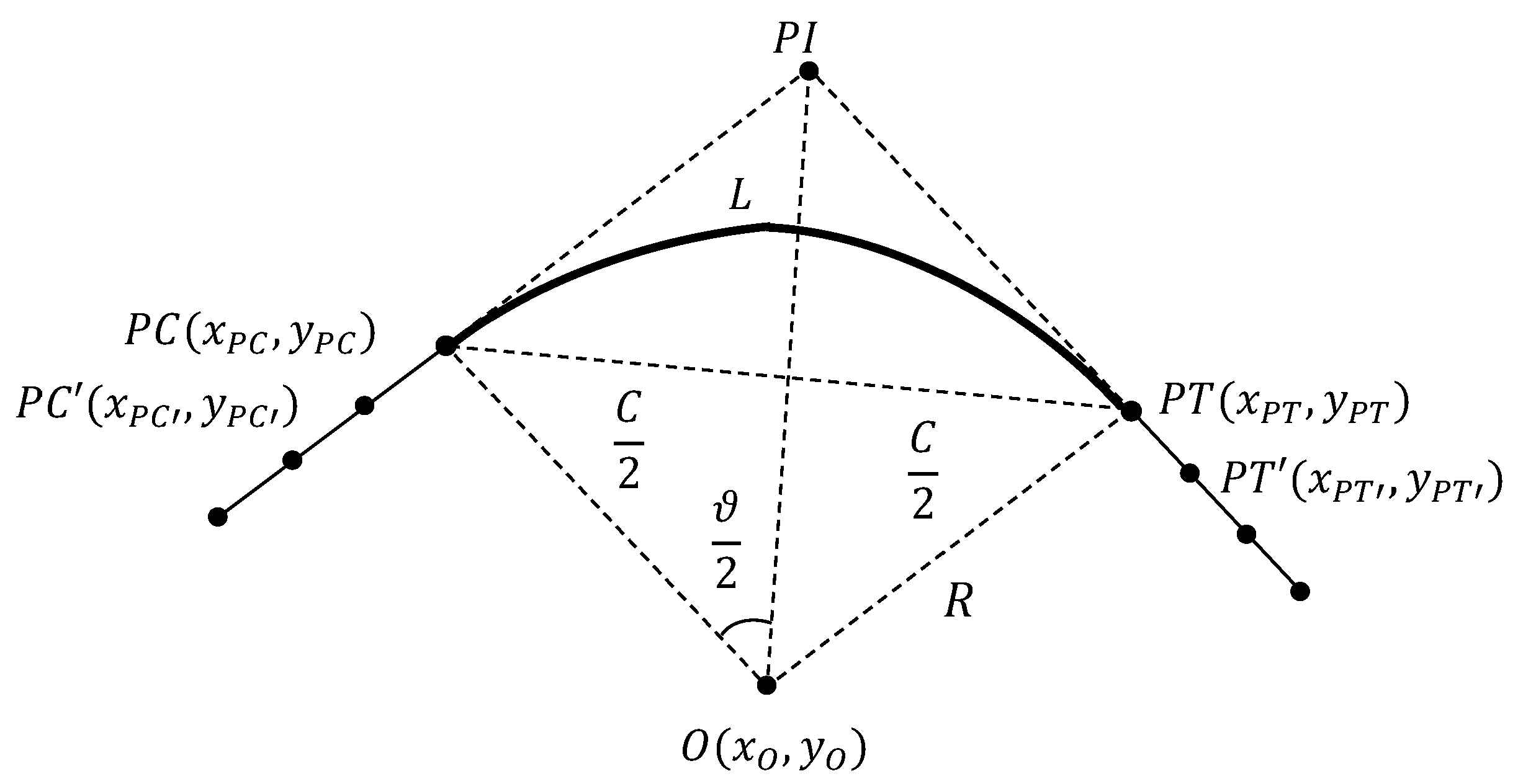
Once the curve identification algorithm has been used to extract the real curves from the predetermined trajectory and define them with their Curvature Points ( P C s ) and Tangency Points ( P T s ) , the optimal speed of each curve must be calculated based on the curve’s main characteristics. The main components of a curve are represented in Figure 2. In the figure, the intersection point, the radius, the curve length, the curve center, the length chord, and the central angle are symbolized by ( P I ) , ( R ) , ( L ) , ( O ) , ( C ) , and ( ϑ ) , respectively.
The curve main parameters identified in Figure 2 are calculated using these equations [42]:
a O P C = ( x P C x P C ) ( y P C y P C )
b O P C = ( y P C x P C ) ( x P C x P C ) ( y P C y P C )
a O P T = ( x P T x P T ) ( y P T y P T )  
b O P T = ( y P T x P T ) ( x P T x P T ) ( y P T y P T )
x o = b O P T b O P C a O P C a O P T
y o = a O P C b O P T b O P C a O P C a O P T + b O P C
R = ( x P C x O ) 2 + ( y P C y O ) 2
C = ( x P T x P C ) 2 + ( y P T y P C ) 2
ϑ = 2 sin 1 ( C 2 R ) 180 π  
L = ϑ · π 180   R
where a O P C and a O P T are the slopes of lines O P C and O P T , respectively, b O P C and b O P T are the intercepts of lines O P C and O P T , respectively, and x o and y o are the coordinates of the curve’s center point.
The extracted curves differ depending on their degree of curvature. The severity of a curve can be measured based on its main parameters. The central angle is most often used such that higher values depict sharper curves. Conversely, lower values depict less sharp curves. Even though it is interesting to consider all the extracted curves, our research only considers the sharp curves identified with a central angle value greater than 40 ° .

3.3. Curve Speed Calculation

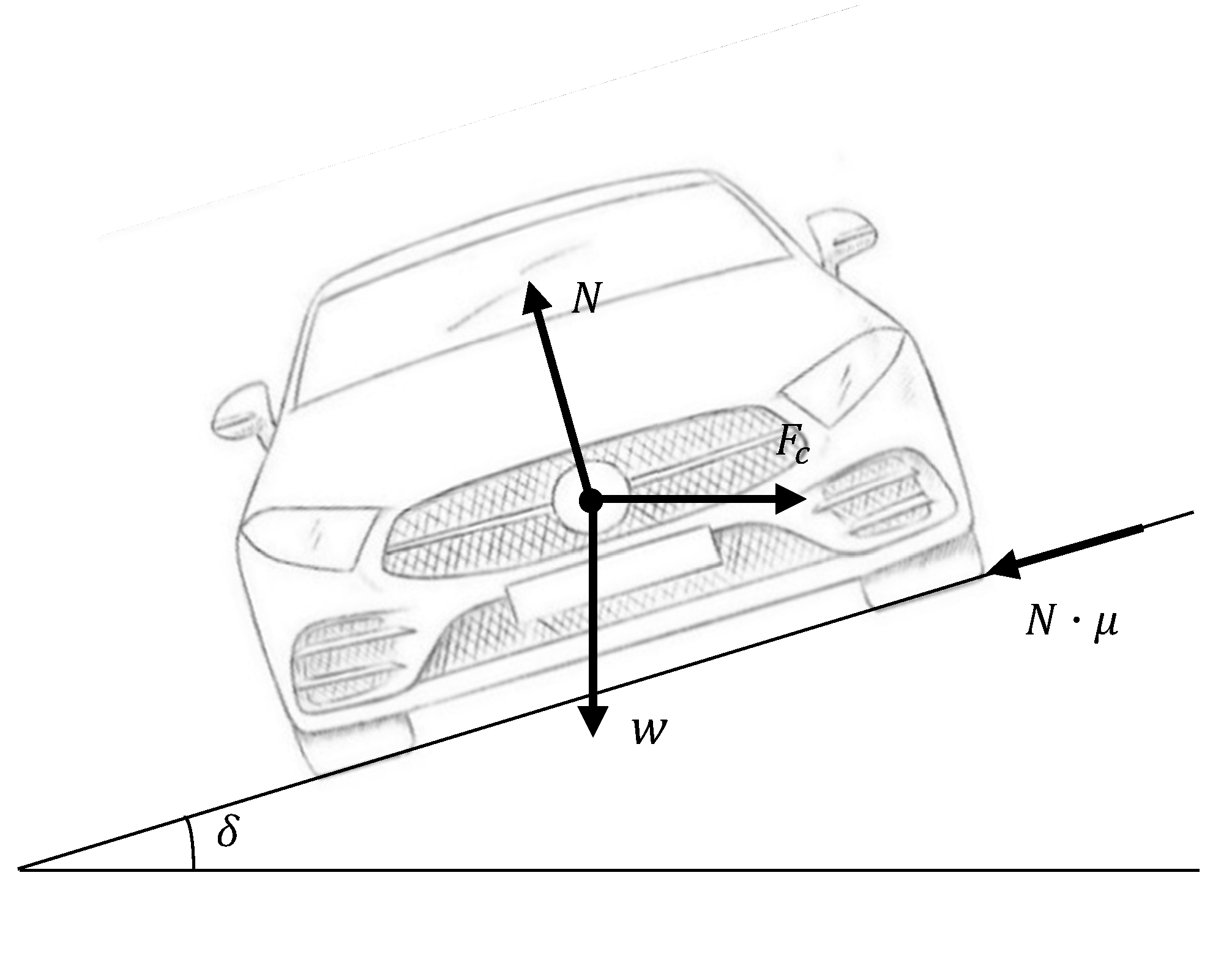
The next step in the SPA is to calculate the optimal speed of each sharp curve included in the trajectory by using the super-elevation angle, friction coefficient, and the extracted characteristics of each curve [43]. Figure 3 presents the forces that were considered in our vehicle model. This figure included the centrifugal force, the slope force, and the rolling resistance force, but the aerodynamic force has been neglected in this model. The reason for excluding the aerodynamic force is that it is typically a smaller force compared to the other forces considered, and the effect of this force can be neglected for the purpose of our study.
During vehicle navigation, its velocity vector changes due to an apparent force applied to the vehicle moving in a curved path acting outward from the center of the curve. This apparent force is called the centrifugal force, which is applied to the vehicle body as:on the human body, defined as:
F c = m v 2 R
where m represents the vehicle mass, v is the vehicle velocity, and R is the curve radius.
In the horizontal direction, the centrifugal force equals the net of the normal force N and the friction force:
F c = N sin δ + N μ cos δ
In the vertical direction, the weight force equals the net of the normal force N and the friction force:
w = N cos δ N μ sin δ
where μ represents the friction coefficient and δ is the bank angle.
According to Newton’s second law, the weight force is given as:
w = m g
Using Equations (13)–(15), the centrifugal force equation becomes:
F c = ( m g cos δ μ sin δ ) ( sin δ + μ cos δ ) = tan δ + μ 1 μ tan δ m g
Using Equations (12) and (16):
tan δ + μ 1 μ tan δ g = v 2 R
By defining the super-elevation i = tan δ and the curvature κ = 1 R , the optimal speed of a curve can be expressed as follows:
v c = ( i + μ ) g ( 1 μ i ) κ
Most curves are super-elevated to help the vehicle to resist the centripetal force effects. The American Association of State Highway and Transportation Officials (AASHTO) recommend a super-elevation rate between 4 % and 12 % [44]. The friction coefficient value depends on vehicle velocity, tire quality, road nature, etc., and it is limited from 0.1 to 0.16 [43].

3.4. Speed Profile Planning

In a real-world driving scenario, the driver tries to control the vehicle by increasing and decreasing the speed depending on the trajectory constraints. Trajectory curves are considered a main factor that the driver should take into account to manage the road properly. Therefore, applying a suitable speed to each part of the trajectory is required to ensure safe and smooth motion throughout the entire trajectory.
In the case of AEVs, a planned speed profile is required to ensure autonomous navigation along the desired trajectory. Speed profile planning depends mainly on the optimal speed of the trajectory’s sharp curves v c and vehicle speed limits to extract the ideal speed for each part of the trajectory and then obtain the speed profile that the vehicle should follow. During vehicle navigation with variable velocity, the speed variation is subjected to an acceleration limit to obtain a smooth motion respecting human comfort. Therefore, a suitable distance is required as a crucial factor in the SPA to reach the desired speed at the right moment within the defined acceleration boundaries. The required distance depends mainly on the actual speed, the desired speed, and the acceleration value, and it is calculated using the following equation:
d = v d 2 v a 2 2 a
where v d is the desired speed, v a is the actual speed, and a is the required acceleration value.
After defining the real curves in the predetermined trajectory, calculating the optimal speed of each curve, and obtaining the required distance to reach the desired speed, the speed profile can be generated and applied to the vehicle through the whole trajectory as explained in the algorithm shown in Figure 4.
First of all, the vehicle starts its motion from zero position with an initial velocity v i ; the maximum speed limit is v m . Based on the actual traveled distance d a , the next curve distance d c , and the distance to maximum speed d m , the algorithm selects between the next curve speed and the maximum speed for the desired speed that the vehicle should reach. If the difference between the curve distance and the actual traveled distance is less than the difference between the distance to maximum speed and the actual traveled distance, then the next curve speed is selected to be the desired speed. Otherwise, the maximum speed limit is selected.
After that, the required distance d r to reach the desired speed is calculated based on Equation (18) in the case where the actual speed is different from the desired speed.
Then, a deceleration a n is applied by the vehicle to reach the desired speed if all the following conditions are satisfied:
  • The actual traveled distance is greater than the difference between the curve distance and the required distance to reach the curve.
  • The actual traveled distance is less than the summation of the curve distance and the curve length l c .
  • The actual speed is greater than the next curve speed.
Otherwise, an acceleration a p is applied to achieve the desired speed.

4. Vehicle Speed Control

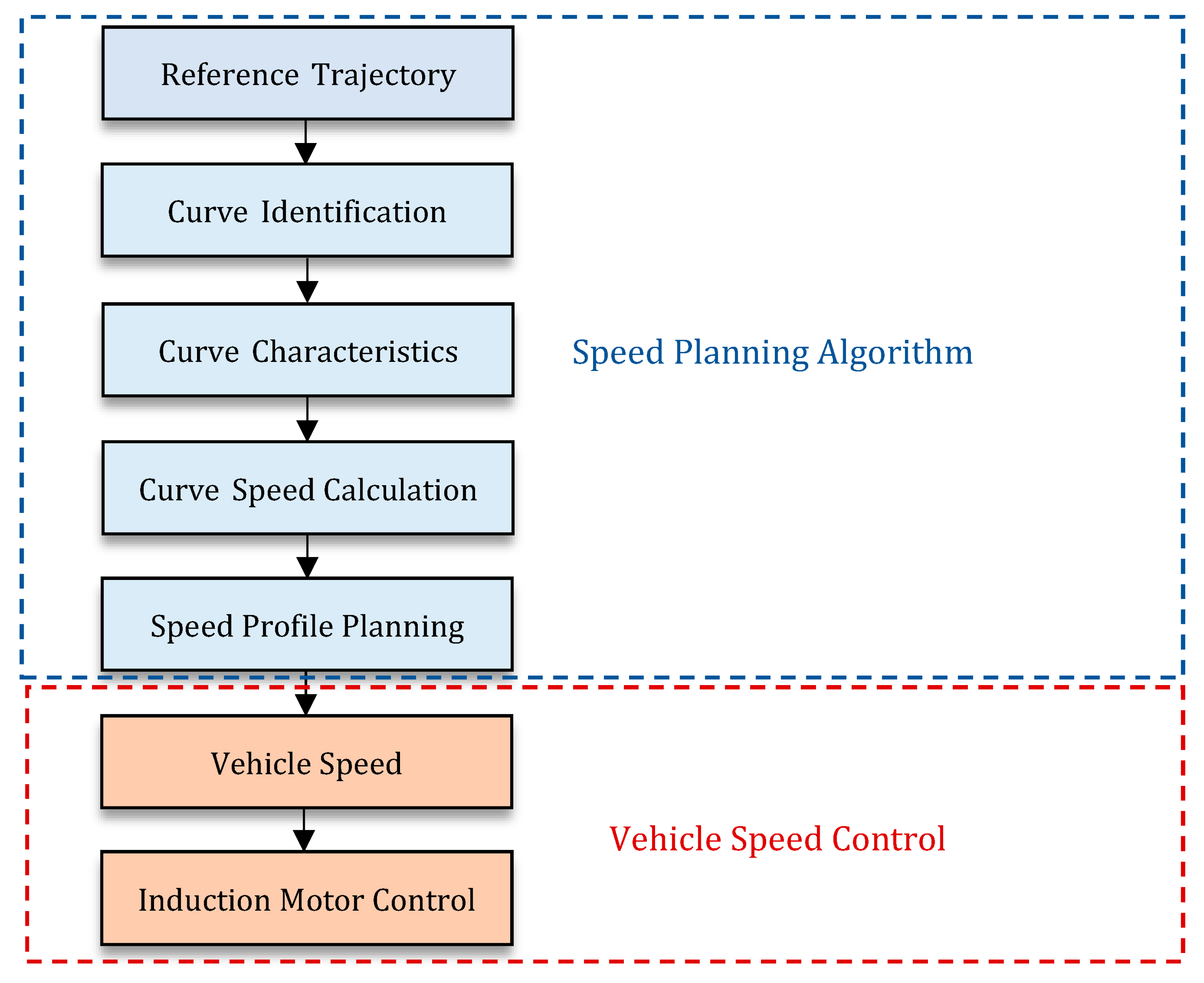
In the previous section, we designed an SPA to generate an appropriate speed profile that will be applied to the AEV based on the predefined trajectory. To correctly emulate the efficient behavior of an electric vehicle, the generated speed profile is extended to control the vehicle drive speed rather than the vehicle speed. As was mentioned before, the IM is considered in this research as the traction part of the AEV due to its ability to reach the reference speed within safe current limits and good energy gain [45,46]. An overall diagram of the speed planning algorithm with vehicle speed control is illustrated in Figure 5.

4.1. IM Model Presentation

For speed control of the IM in the stationary reference ( α β ) frame, the dynamic model can be presented as follows:
V s α = γ · i s α + σ · L s · d i s α d t T m r T r ϕ r α T m r · ω · ϕ r β
V s β = γ · i s β + σ · L s · d i s β d t T m r T r ϕ r β + T m r · ω · ϕ r α
ϕ r α = L m · i s α T r · d ϕ r α d t T r · ω · ϕ r β
ϕ r β = L m · i s β T r · d ϕ r β d t + T r · ω · ϕ r α
J · d Ω d t = T e T L f · Ω
The electromagnetic torque equation is defined as a cross multiplication of rotor flux and stator currents:
T e = η · ( ϕ r α · i s β ϕ r β · i s α )
The magnitude of the rotor flux ϕ r is deduced as:
ϕ r = ϕ r α 2 + ϕ r β 2
where: σ = 1 L m 2 L s · L r ; γ = R s + L s ( 1 σ ) T r ; T m r = L m L r ; T r = L r R r ; η = p L m L r .
Additionally, V s α _ β , i s α _ β , ϕ r α _ β , R s ,   R r , L s , L r , L m , ω , Ω , J , f ,   p , and T L are stator α β frame voltage, stator α β frame current, stator α β frame flux, stator resistance, rotor resistance, stator inductance, rotor inductance, mutual inductance, electrical speed, mechanical speed, motor inertia, viscous damping coefficient, number of pair poles, and load torque.

4.2. Back-Stepping SVM Control Design

The back-stepping control approach is a technique for recursive design that links the development of a feedback control law with the choice of a Lyapunov function that guarantees the asymptotic stability of the whole system.
In our research, a back-stepping control technique was designed in a stationary reference ( α β ) frame to control the speed of an AEV induction motor. The designed controller contains four control loops, two outer loops, and two inner loops, with a control law for each control loop. The outer loops were designed to control the speed and rotor flux. The results of these two loops, which contain the subtraction of cross multiplication and the summation of direct multiplication of the global stator currents and rotor flux, were used as set-points for the two inner loops. The choice of a suitable Lyapunov function ensures the overall system’s control law.
  • Step 1: Outer loops control
The outer loops contain the speed and the rotor flux control. Therefore, its tracking errors are defined as follows:
e 1 = Ω r e f Ω
e 2 = ϕ r r e f 2 ϕ r 2
Thus, the gradients of these dynamic errors are:
d e 1 d t = d Ω r e f d t d Ω d t
d e 2 d t = d ϕ r r e f 2 d t d ϕ r 2 d t
By using the magnetic, mechanical, and electromagnetic torque equations, Equations (29) and (30) become:
d e 1 d t = d Ω r e f d t 1 J [ η · ( ϕ r α · i s β ϕ r β · i s α ) T L f · Ω ]
d e 2 d t = d ϕ r r e f 2 d t 2 · L m T r ( ϕ r α · i s α + ϕ r β · i s β ) + 2 T r · ϕ r 2
To ensure the stability of the outer speed and rotor flux loops, a first positive definite Lyapunov candidate V 1 is defined as:
V 1 = 1 2 e 1 2 + 1 2 e 2 2
The time derivative of Equation (33) is:
d V 1 d t = e 1 d e 1 d t + e 2 d e 2 d t
By substituting Equations (31) and (32) in Equation (34), we obtain the following:
d V 1 d t = e 1 ( d Ω r e f d t 1 J [ η · ( ϕ r α · i s β ϕ r β · i s α   ) T L f · Ω ] + k 1 · e 1 ) k 1 · e 1 2 + e 2 ( d ϕ r r e f 2 d t 2 · L m T r ( ϕ r α · i s α + ϕ r β · i s β ) + 2 T r · ϕ r 2 + k 2 · e 2 ) k 2 · e 2 2
where k 1 and k 2 are positive closed loop constants that ensure the convergence of the speed and rotor flux errors to zero.
For a positive definite Lyapunov function, its derivative must be seminegative definite to ensure the asymptotic stability of the outer loops:
d V 1 d t = k 1 · e 1 2 k 2 · e 2 2 < 0
By equaling Equations (35) and (36), the outcome of the outer loops is deduced as:
C 1 r e f = J η ( d Ω r e f d t + T L J + f J · Ω + k 1 · e 1 )
C 2 r e f = T r 2 · L m ( d ϕ r r e f 2 d t + 2 T r · ϕ r 2 + k 2 · e 2 )
  • Step 2: Inner loops control
The inner loops use the outcome of the outer loops as a reference to calculate the control laws V s α and V s β . The tracking errors are defined as:
e 3 = C 1 r e f C 1
e 4 = C 2 r e f C 2
Thus, the gradients of these dynamic errors are:
d e 3 d t = d C 1 r e f d t d C 1 d t
d e 4 d t = d C 1 r e f d t d C 2 d t
By using the outcome of the speed and rotor flux outer loops beside the electrical and magnetic equations, the gradients of the inner loops errors become:
d e 3 d t = f k 1 · J η · J ( η · C 1 f · ω T L ) + ( 1 T r + γ σ · L s ) C 1 + ω · C 2 + T m r σ · L s · ω · ϕ r 2 + ϕ r β σ · L s · V s α ϕ r α σ · L s · V s β
d e 4 d t = 2 k 2 · T r L m ( L m T r · C 2 1 T r · ϕ r 2 ) + ( 1 T r + γ σ · L s ) C 2 ω · C 1 T m r T r · σ · L s · ϕ r 2 L m T r ( i s α 2 + i s β 2 ) ϕ r α σ · L s · V s α ϕ r β σ · L s · V s β
For the stability of the inner loops, a second positive definite Lyapunov candidate V 2 is defined as:
V 2 = 1 2 e 3 2 + 1 2 e 4 2
Its derivative is derived as follows:
d V 2 d t = e 3 d e 3 d t + e 4 d e 4 d t
By using Equations (43) and (44), Equation (46) becomes:
d V 2 d t = e 3 ( f k 1 · J η · J ( η · C 1 f · ω T L ) + ( 1 T r + γ σ · L s ) C 1 + ω · C 2 + T m r σ · L s · ω · ϕ r 2 + ϕ r β σ · L s · V s α ϕ r α σ · L s · V s β + k 3 e 3 ) + e 4 ( 2 k 2 · T r L m ( L m T r · C 2 1 T r · ϕ r 2 ) + ( 1 T r + γ σ · L s ) C 2 ω · C 1 T m r T r · σ · L s · ϕ r 2 L m T r ( i s α 2 + i s β 2 ) ϕ r α σ · L s · V s α ϕ r β σ · L s · V s β + k 4 e 4 ) k 3 · e 3 2 k 4 · e 4 2
where k 3 and k 4 are positive constants used to control the convergence rate of the inner loops. To ensure the asymptotic stability of the inner loops and, therefore, the whole system, the derivative of the second candidate Lyapunov function must be seminegative definite:
d V 2 d t = k 3 · e 3 2 k 4 · e 4 2 < 0
To satisfy Equation (48), the control law is deduced as follows:
V s α = σ · L s ϕ r 2 [ ϕ r α ( 2 k 2 · T r L m ( L m T r · C 2 1 T r · ϕ r 2 ) + ( 1 T r + γ σ · L s ) C 2 ω · C 1 T m r T r · σ · L s · ϕ r 2 L m T r ( i s α 2 + i s β 2 ) + k 4 e 4 ) ϕ r β ( f k 1 · J η · J ( η · C 1 f · ω T L ) + ( 1 T r + γ σ · L s ) C 1 + ω · C 2 + T m r σ · L s · ω · ϕ r 2 + k 3 e 3 ) ]
V s β = σ · L s ϕ r 2 [ ϕ r β ( 2 k 2 · T r L m ( L m T r · C 2 1 T r · ϕ r 2 ) + ( 1 T r + γ σ · L s ) C 2 ω · C 1 T m r T r · σ · L s · ϕ r 2 L m T r ( i s α 2 + i s β 2 ) + k 4 e 4 ) + ϕ r α ( f k 1 · J η · J ( η · C 1 f · ω T L ) + ( 1 T r + γ σ · L s ) C 1 + ω · C 2 + T m r σ · L s · ω · ϕ r 2 + k 3 e 3 ) ]

4.3. Load Torque Estimation

The load torque was assumed to be an unknown variable during the design of the previous control loops. A torque sensor can be used directly to measure the load torque, which raises the system cost. Therefore, a back-stepping observer is proposed in this part for estimating the applied load torque and reducing system uncertainty.
From the mechanical equation of the IM, the load torque can be written as:
T L = T e f · Ω J · d Ω d t
The error of the estimated load torque is given as:
e 5 = T L T ^ L
The time derivative of the estimation error is derived as:
d e 5 d t = d T L d t d T ^ L d t
Assuming that the load torque only changes at particular instants, then it can be considered as a constant and Equation (53) becomes:
d e 5 d t = d T ^ L d t
For the stability of the estimated load torque error, a positive definite Lyapunov function V 3 is defined as follows:
V 3 = 1 2 e 5 2
The derivative of Equation (55) can be expressed as:
d V 3 d t = e 5 ( d e 5 d t + k 5 · e 5 ) k 5 · e 5 2
where k 5 is a positive constant.
To ensure the asymptotic stability, the derivative of the Lyapunov candidate must be seminegative definite:
d V 3 d t = k 5 · e 5 2 < 0
Therefore, the expression of the estimated load torque is deduced as follows:
T ^ L = T e f · Ω J · d Ω d t 1 k 5 · d T ^ L d t

4.4. SVM Strategy Control

Space vector modulation became an efficient technique for switching power inverters to control an AC drive. This technique works on minimizing current harmonic distortion by selecting suitable switching vectors. As a result, SVM can improve torque and flux ripple phenomena and accomplish an effective control loop.
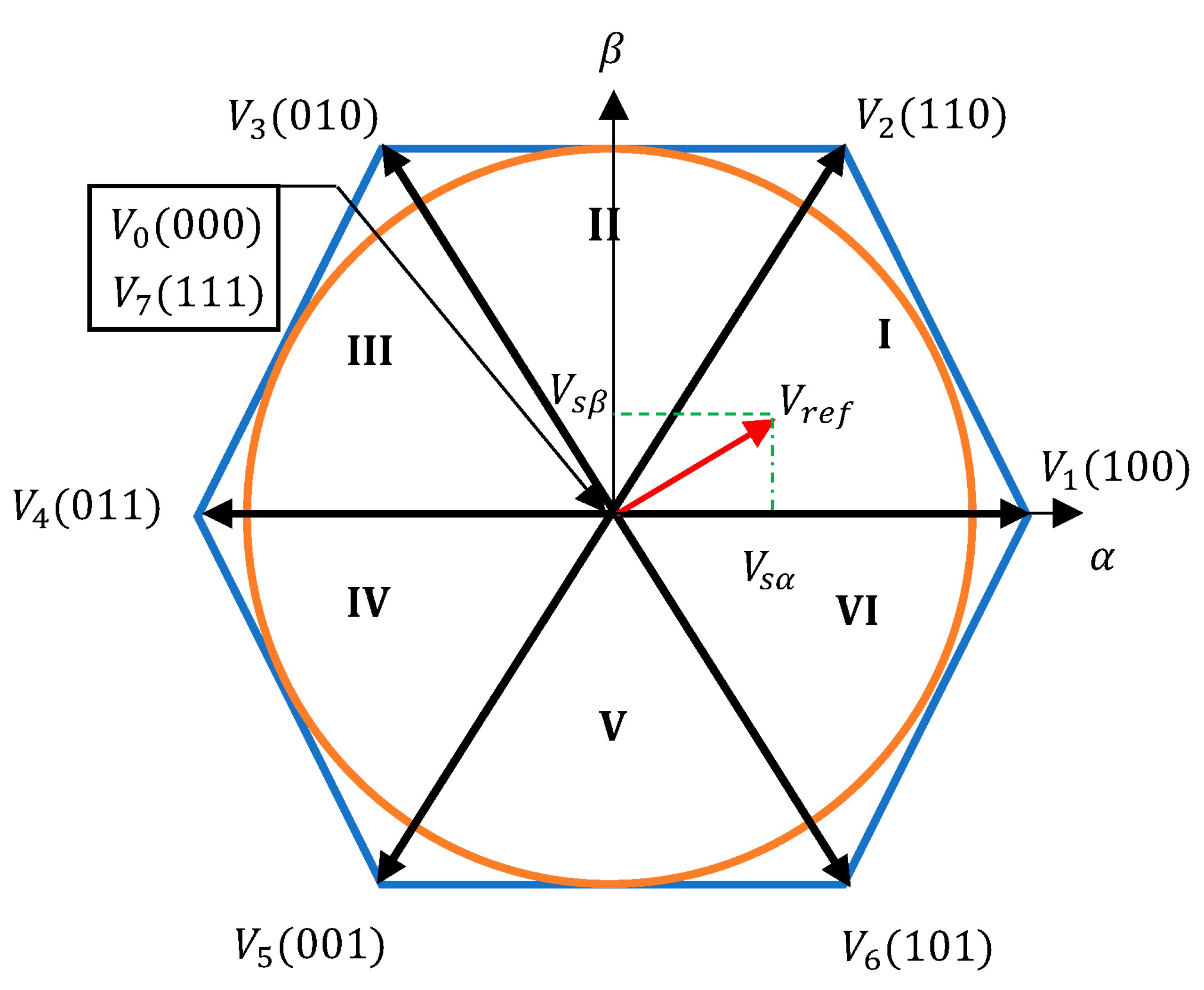
The principle of the SVM strategy is to use a digital algorithm to obtain an inverter switch control sequence to generate an output voltage vector that approximates the reference voltage vector as closely as possible. The three desired sinusoidal voltages at the output are represented by a single vector called the reference voltage vector. This vector is best approximated at each sampling time from eight voltage vectors [47] by applying two adjacent vectors and zero vectors V 0 and V 7 . Simple projections are used to determine the times T 1 and T 2 of the two adjacent vectors in a stationary reference ( α β ) frame:
T 1 = T s 2 V d c ( 6 · V s β r e f 2 · V s α _ r e f )
T 2 = 2 · T s V d c · V s α _ r e f
where V s α _ r e f and V s β _ r e f denote the reference voltage vectors, T 1 and T 2 are the corresponding vectors’ durations, V d c is the D C bus voltage, and T s is the sampling time. The space vector diagram for a two-level inverter is shown in Figure 6.
The scheme of the global back-stepping control technique with SVM strategy and load torque estimation is shown in Figure 7:

5. Results and Discussion

In this section, we present the results and discuss the proposed control algorithm applied to the AEV by using MATLAB/Simulink software and dSPACE 1104 real-time interface. The experiment was conducted in the laboratory of electrical engineering (LGEB). The analysis results are divided into three parts. The first part presents the speed profiles obtained from applying the proposed SPA to predetermined trajectories. The second part contains a comparative study of the proposed back-stepping technique with the SVM strategy and the switching table-based classical DTC. The third part demonstrates the performance of the back-stepping technique in an electric vehicle application by controlling the IM speed to follow the desired speed profiles.

5.1. Speed Planning Results

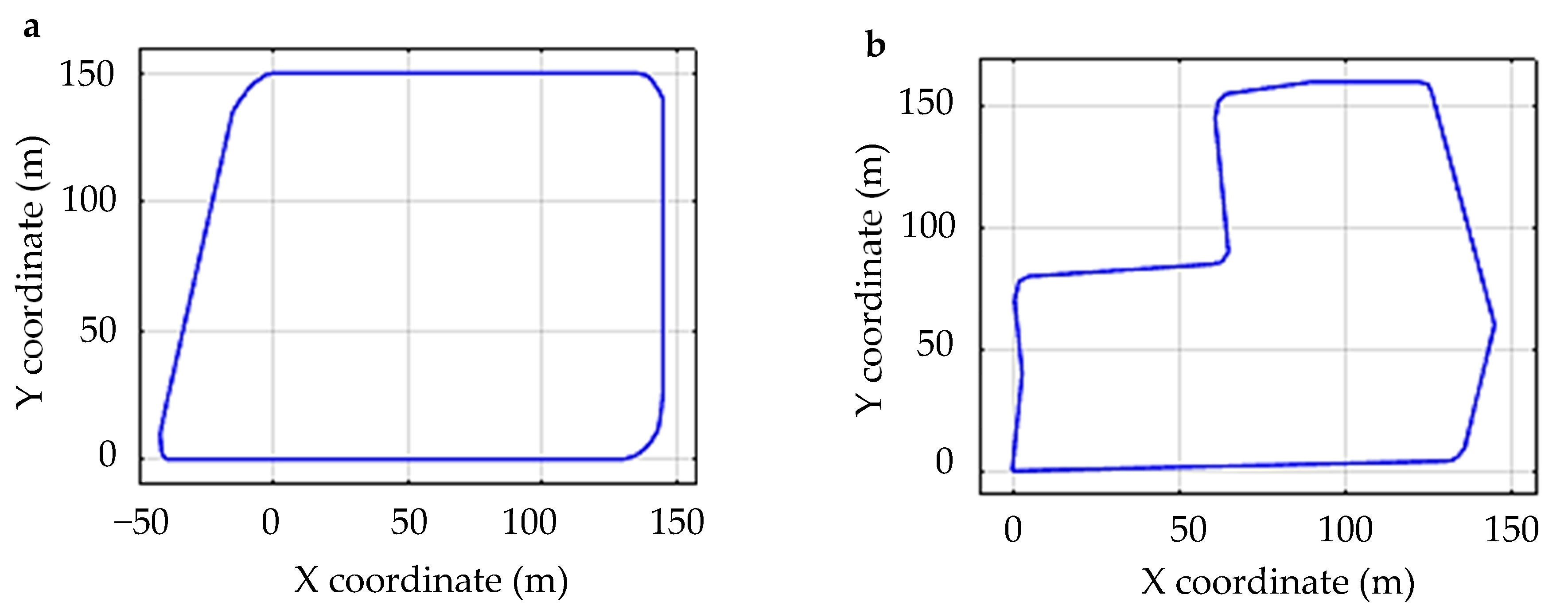
Two proposed trajectories with distinct profiles and curve features were studied in this research to ensure we applied our algorithm to different circumstances (Figure 8). The first trajectory has four sharp curves with a total distance of 592   m , while the second has six sharp curves with a total distance of 557   m . The figures are specified as (a) for the first trajectory speed profile and (b) for the speed profile of the second trajectory. The parameters used during vehicle navigation in both trajectories 1 and 2 are listed in Table 1. The vehicle starts its motion from a zero position with an initial velocity of v i = 0   Km / h ; the maximum allowed speed is v m = 70   Km / h . To eliminate jerking and ensure passenger comfort by providing a smooth transition between speeds, a longitudinal acceleration of 8   m / s 2 is applied.
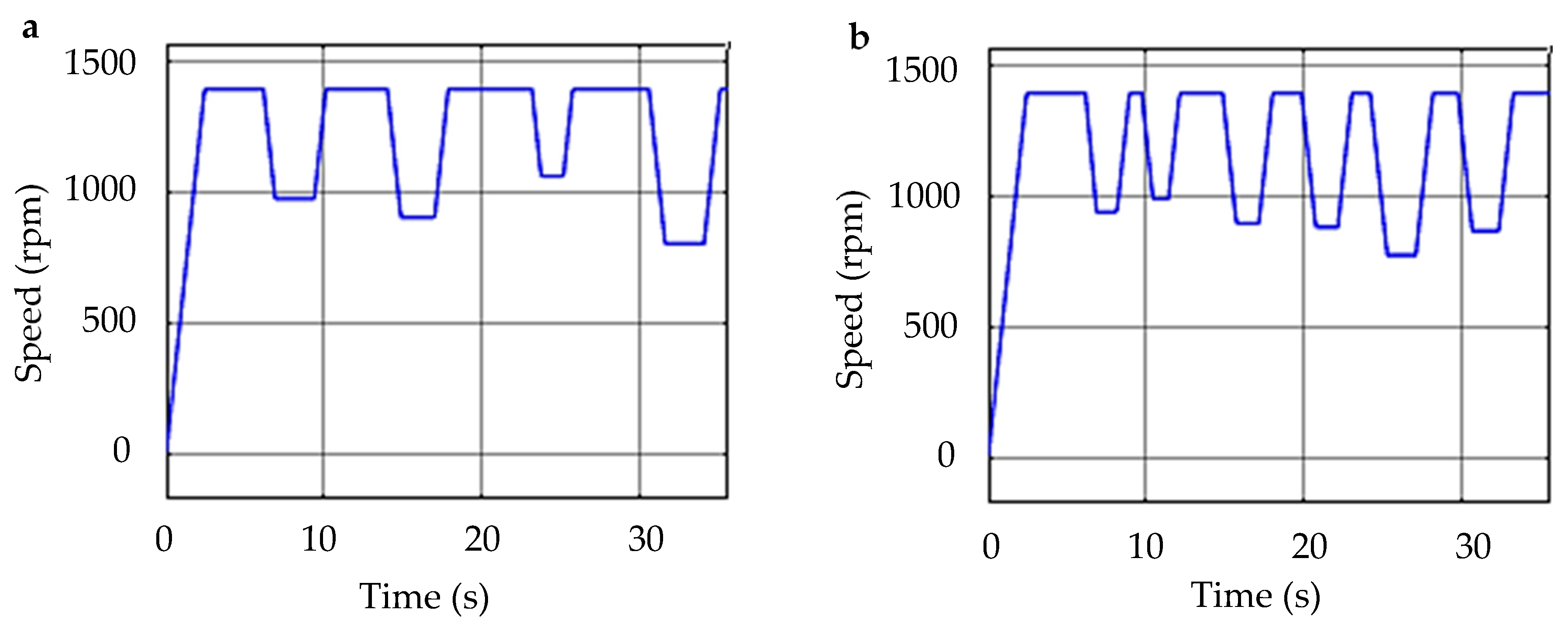
Figure 9 presents the results obtained from applying the proposed SPA to trajectories 1 and 2, respectively. These results explain the ideal speed that the vehicle should follow during its navigation through each trajectory. With four sharp curves included in the first trajectory and six in the second one, different ideal speeds were calculated based on the main characteristics of each curve. Then, by applying a suitable acceleration with respect to the required distance to reach each ideal speed, two speed profiles with soft transitions were generated. Applying such an algorithm on the AEV during its navigation through the predetermined trajectories guarantees a small path tracking error, vehicle energy optimization, passenger comfort against longitudinal acceleration/deceleration, and increases the vehicle’s running safety level.
To efficiently study the longitudinal behavior of an AEV, the extracted vehicle speed profiles are used to obtain speed profiles of the IM and then control its speed. This last can be calculated as a function of vehicle speed if the parameters of gear ratio and wheel radius are known. Therefore, by choosing values of gear ratio g r = 1.5 and wheel radius r w = 0.2   m , the speed profiles of the motor in rpm can be presented as shown in Figure 10.

5.2. Back-Stepping SVM and Classical DTC Comparative Analysis

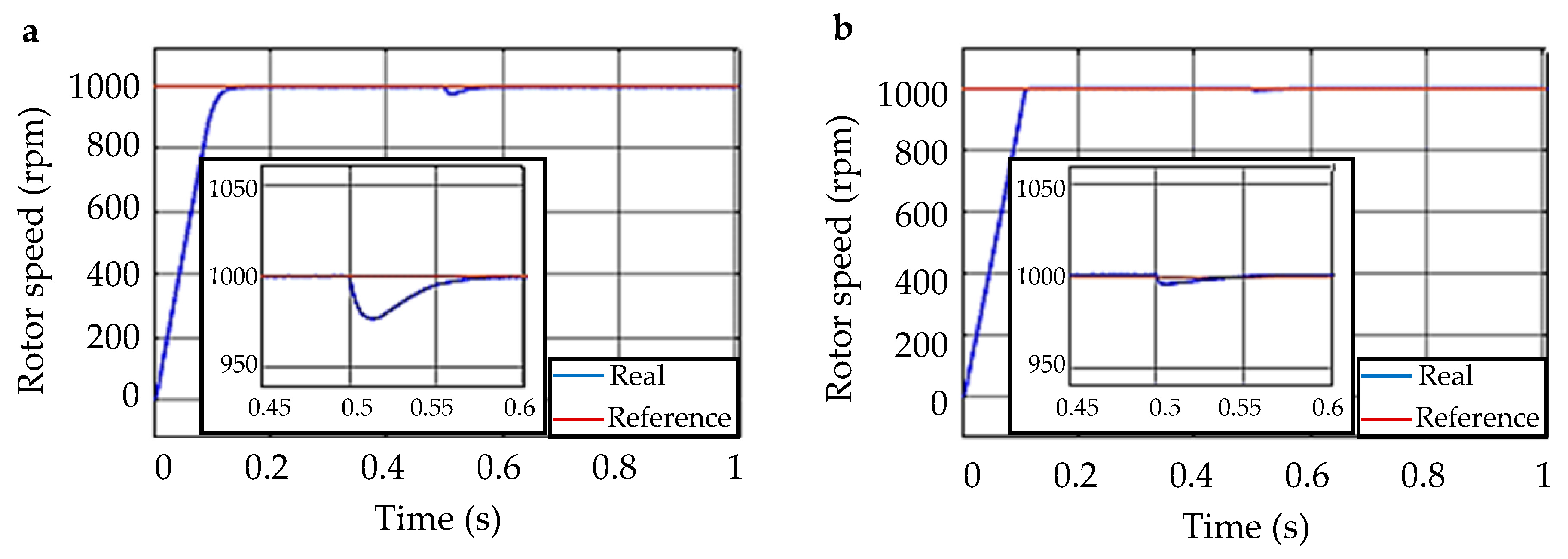
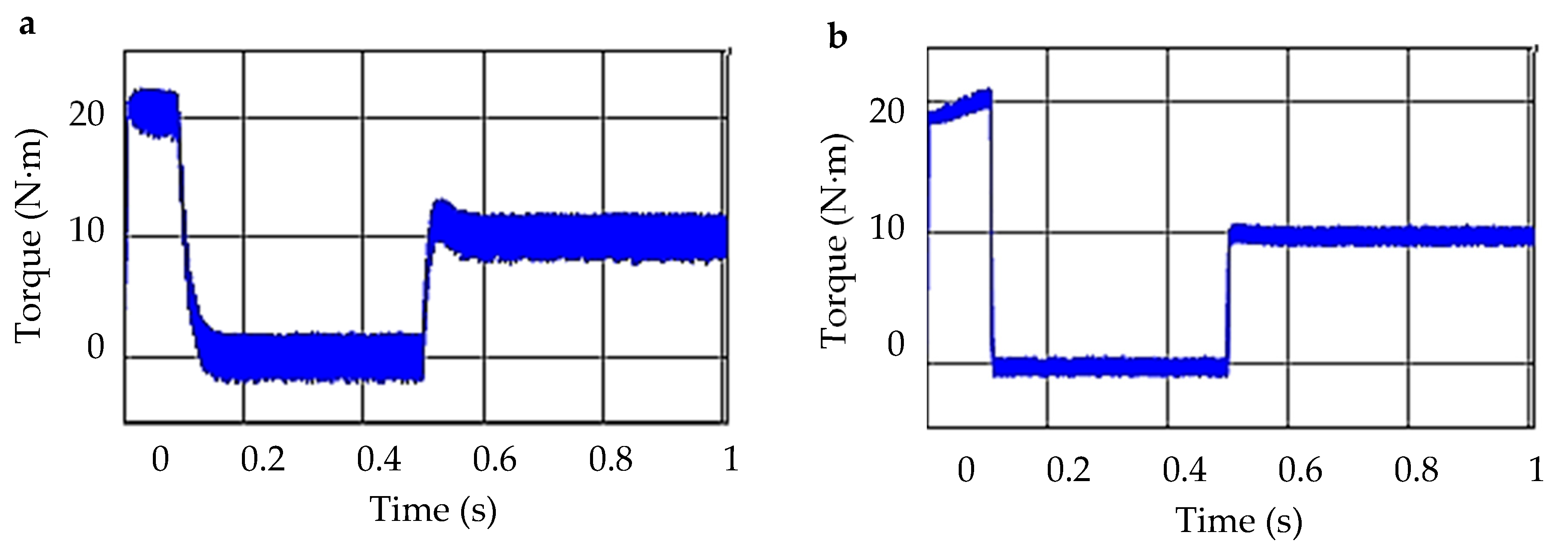
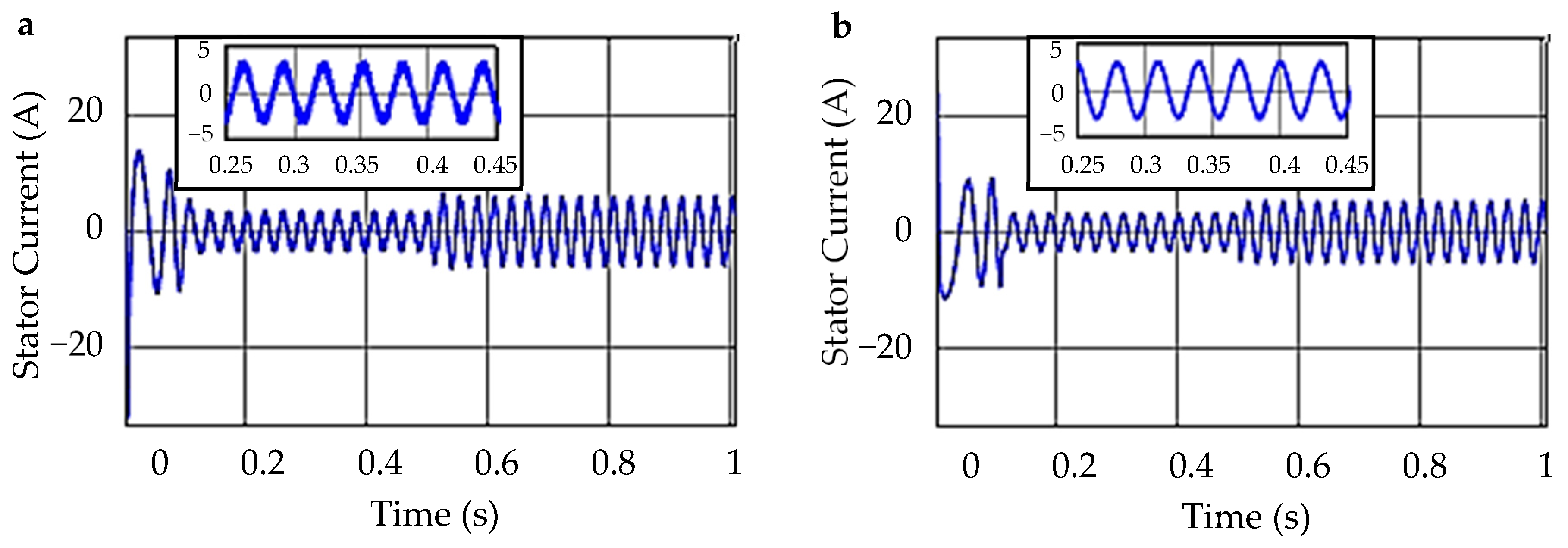
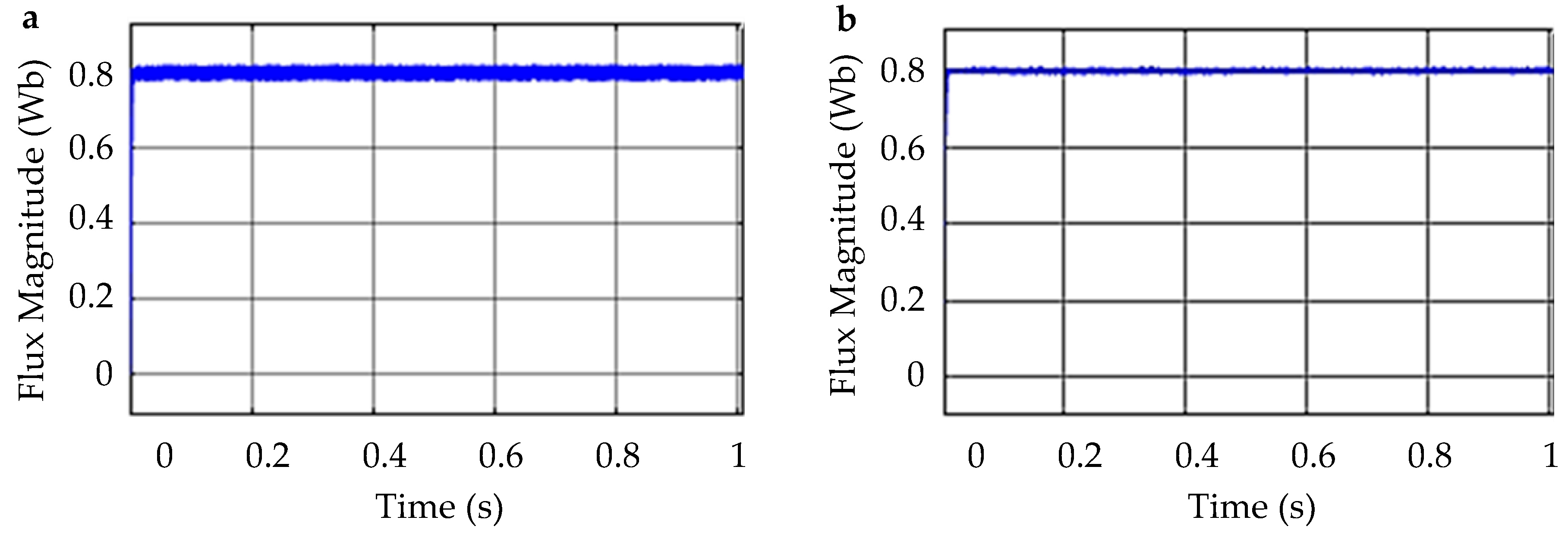
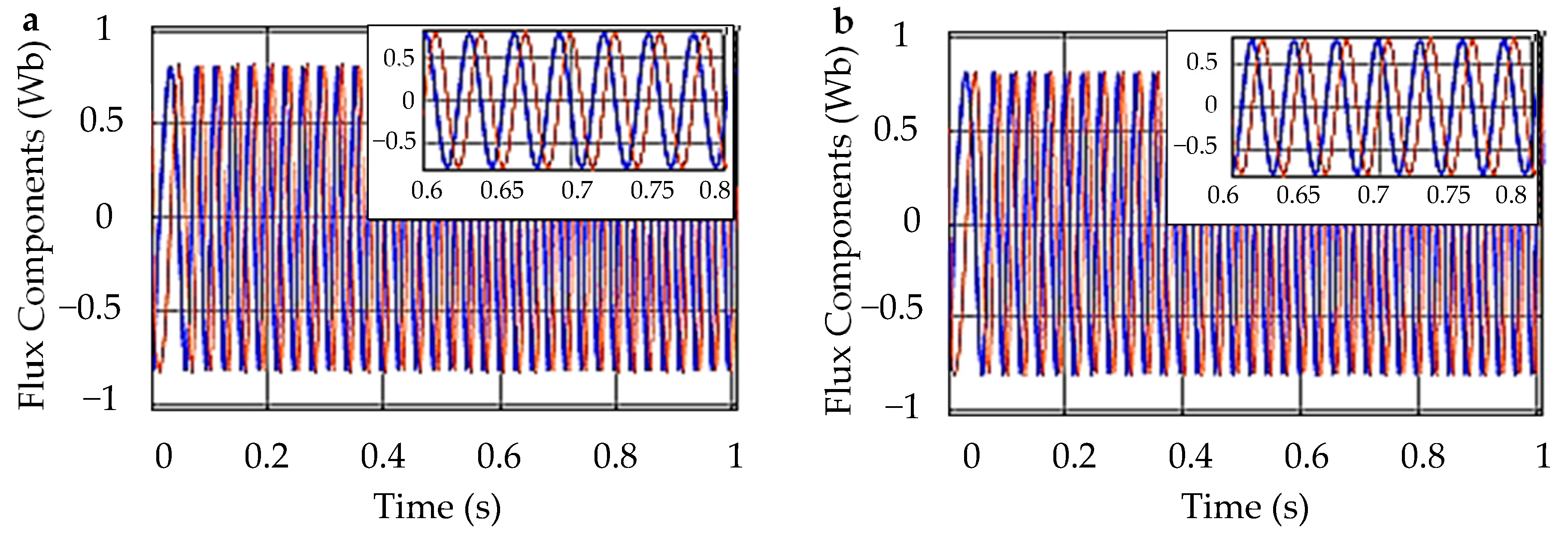
This part showcases the simulation outcomes of the back-stepping control algorithm applied to the IM via the use of MATLAB/Simulink software. In order to display the effectiveness of the designed back-stepping control technique, a comparative analysis was conducted with the classical DTC method. The control algorithm’s robustness was verified during startup and steady state with load application and are depicted in Figure 11, Figure 12, Figure 13, Figure 14 and Figure 15. The classical DTC figures are presented in (a), while the back-stepping SVM technique figures are presented in (b). The given parameters in Table 2 were utilized to obtain the simulation outcomes for a three-phase induction motor.
Figure 11, Figure 12, Figure 13, Figure 14 and Figure 15 demonstrate the response of rotor speed, electromagnetic torque, stator phase current, stator flux magnitude, and stator flux components for both classical DTC and back-stepping SVM techniques during startup and steady state at a reference speed of 1000   rpm , with a load application of 10   N · m at 0.5   s . Figure 11 displays the speed response and shows that both techniques satisfactorily track the reference speed without overshoot. The back-stepping SVM technique (Figure 11b) responds quickly and compensates for speed error caused by applied load torque, unlike the classical DTC technique (Figure 11a). Figure 12 presents the electromagnetic torque response, indicating that both techniques exhibit fast dynamics and a good response. However, the classical DTC technique (Figure 12a) has high torque ripples while back-stepping has a lower level of ripples, as shown in Figure 12b. In Figure 13, the stator phase current shape has a good sinusoidal waveform, and the back-stepping SVM technique generates a smoother current shape with reduced harmonics, as shown in the zoom of Figure 13b, due to the optimal selection of the voltage reference. Finally, Figure 14 and Figure 15 demonstrate the stator flux magnitude and components. Both techniques produce good waveforms for the flux components and respond quickly to the flux magnitude. However, the back-stepping SVM has lower flux ripples than the classical DTC.

5.3. Vehicle Speed Control Results

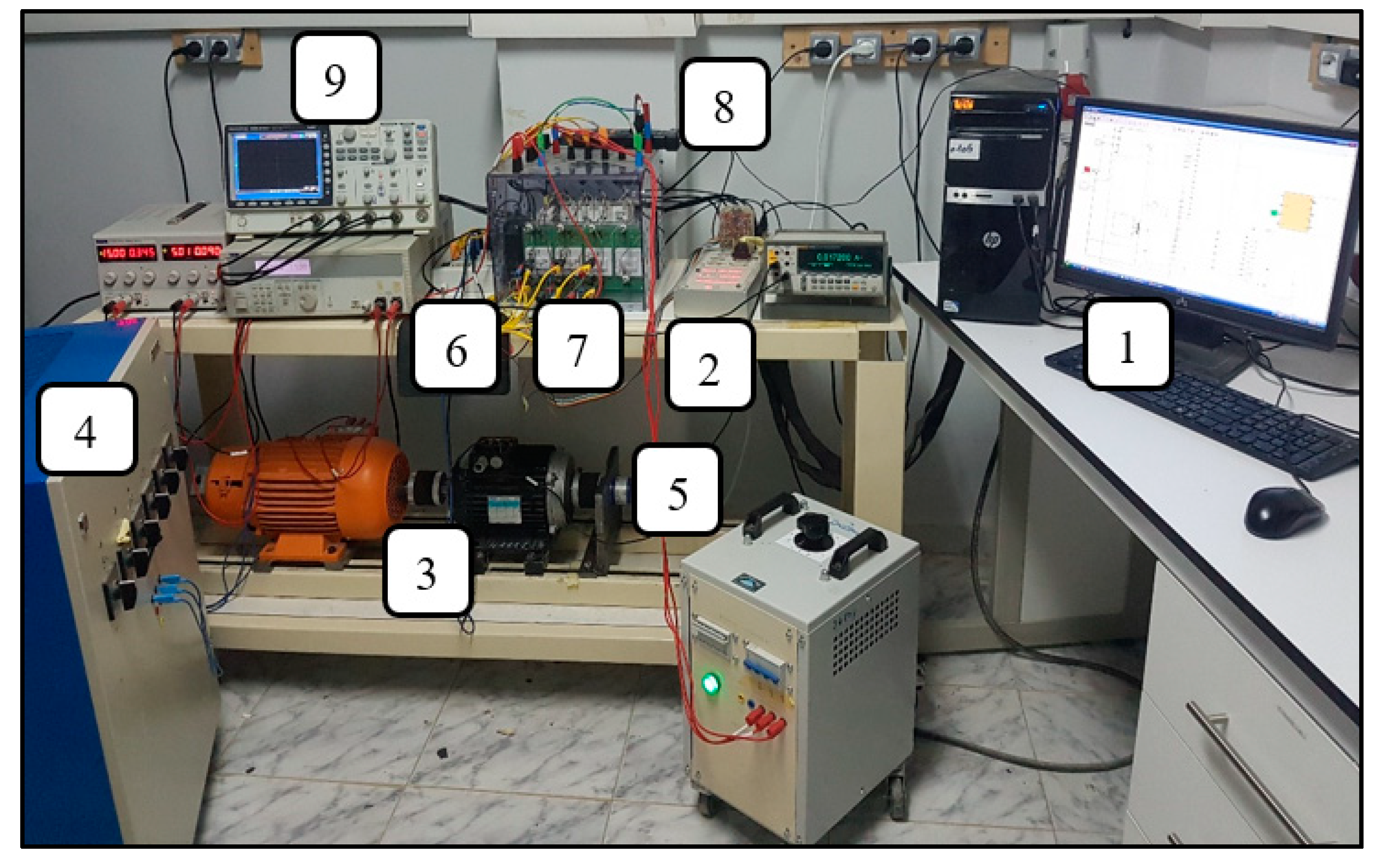
In this part, the results of using the back-stepping technique to control the vehicle so that it follows the speed generated by the designed SPA are presented. The implementation part of the electric vehicle IM is shown in Figure 16; it is essentially composed of: 1—supervision desktop with MATLAB/Simulink software, 2—dSPACE 1104 card, 3—squirrel cage IM and DC machine, 4—resistive load, 5—incremental encoder, 6—current sensor, 7—power electronics Semikron converter, 8—voltage sensor, and 9—digital oscilloscope.
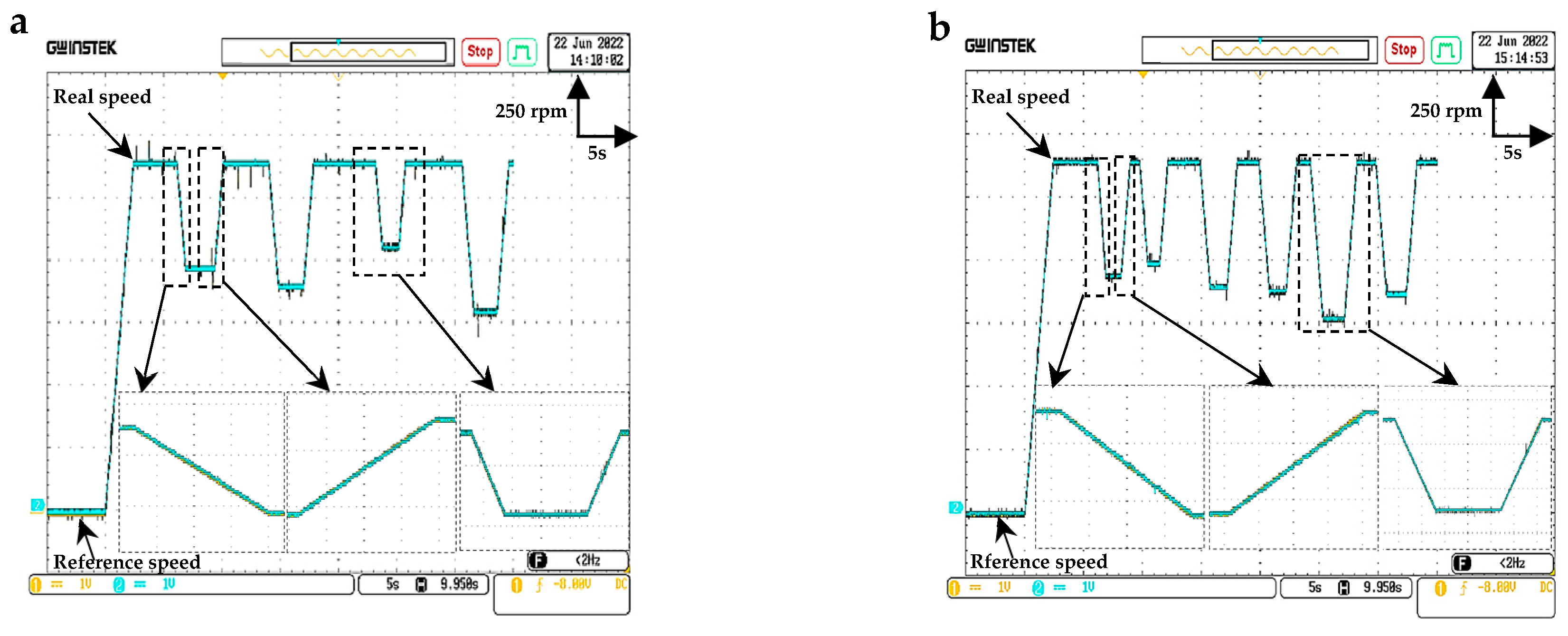
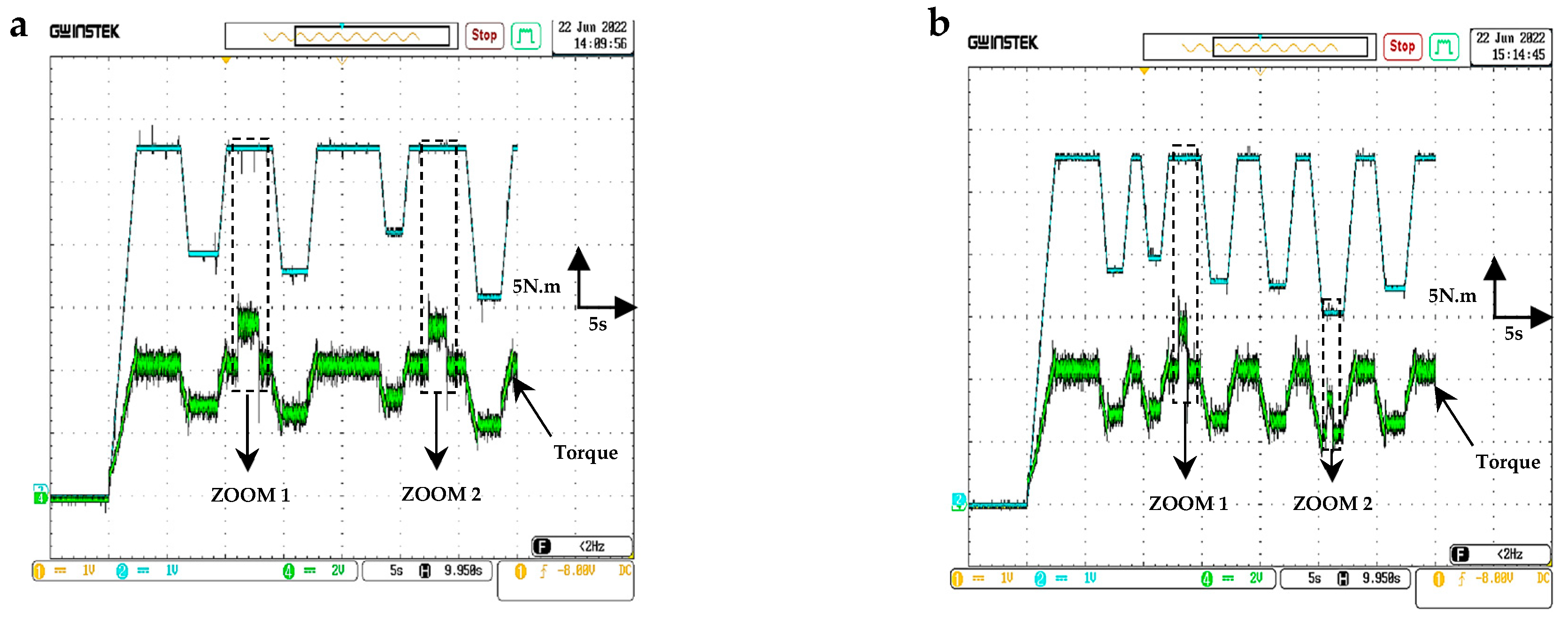
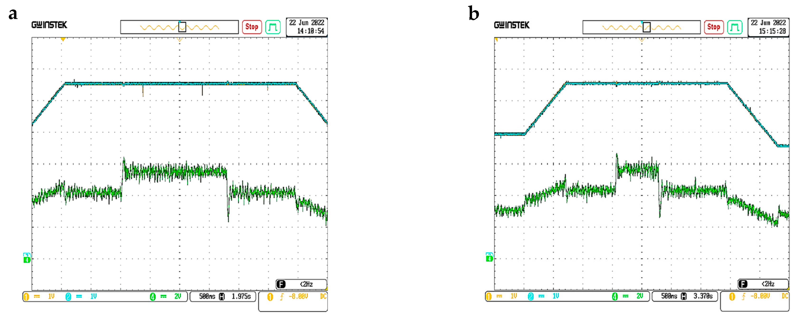
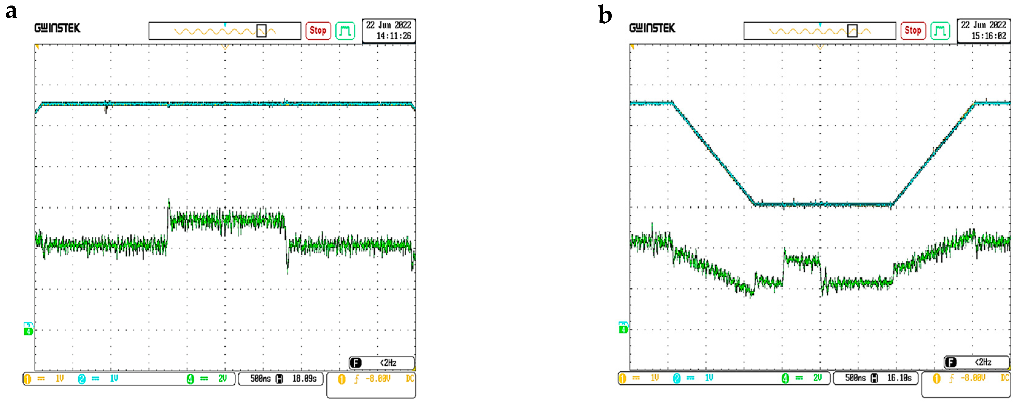
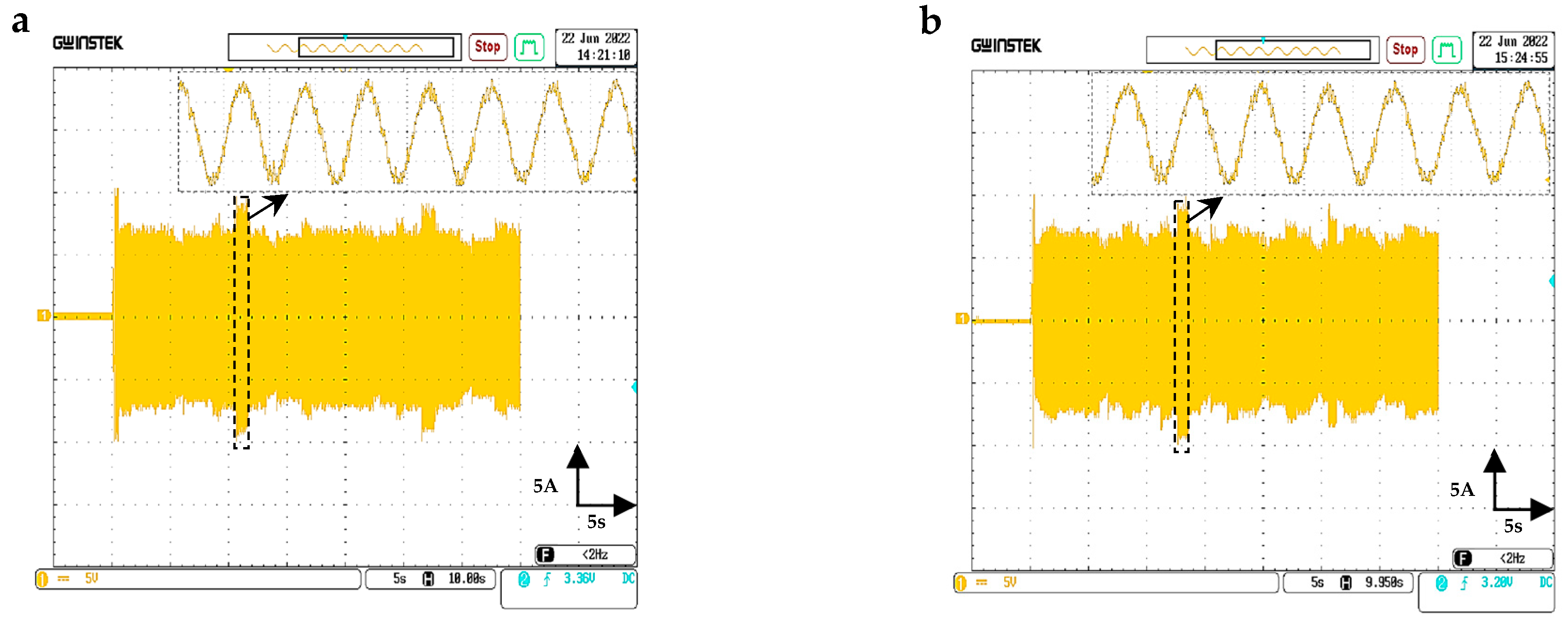
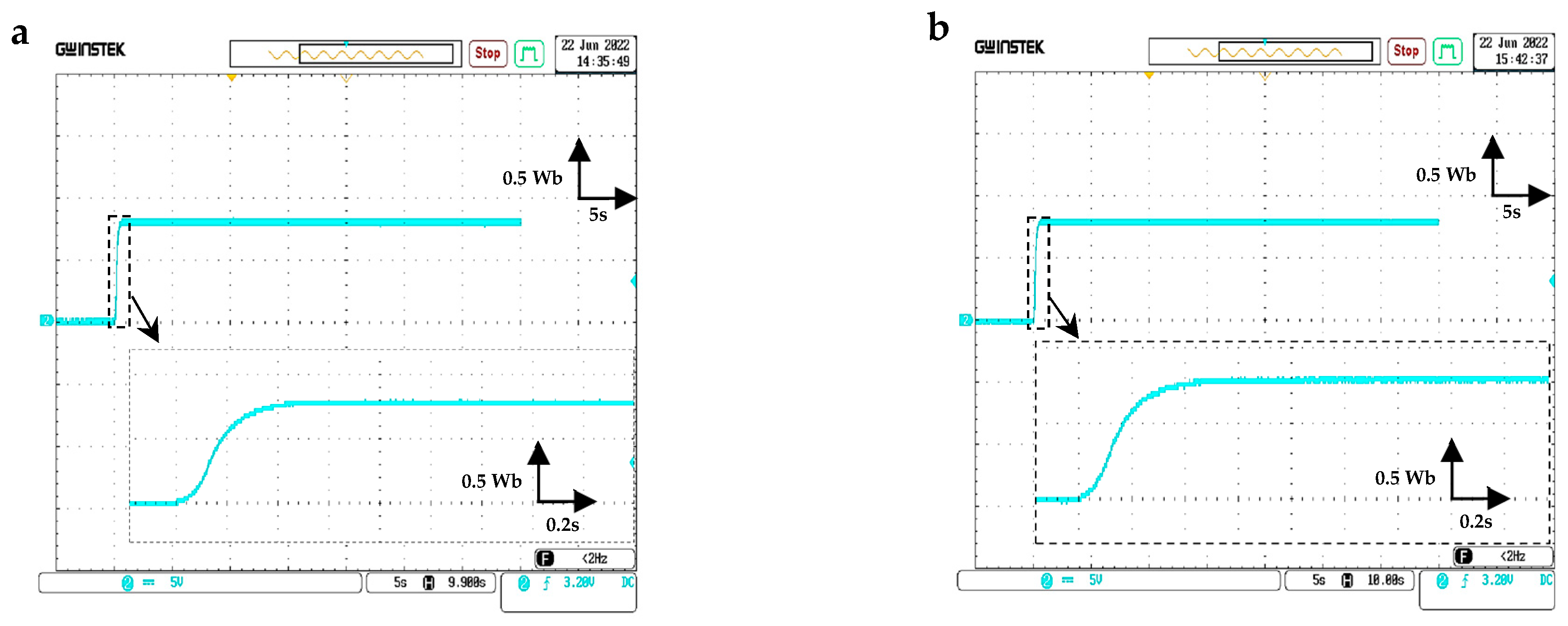
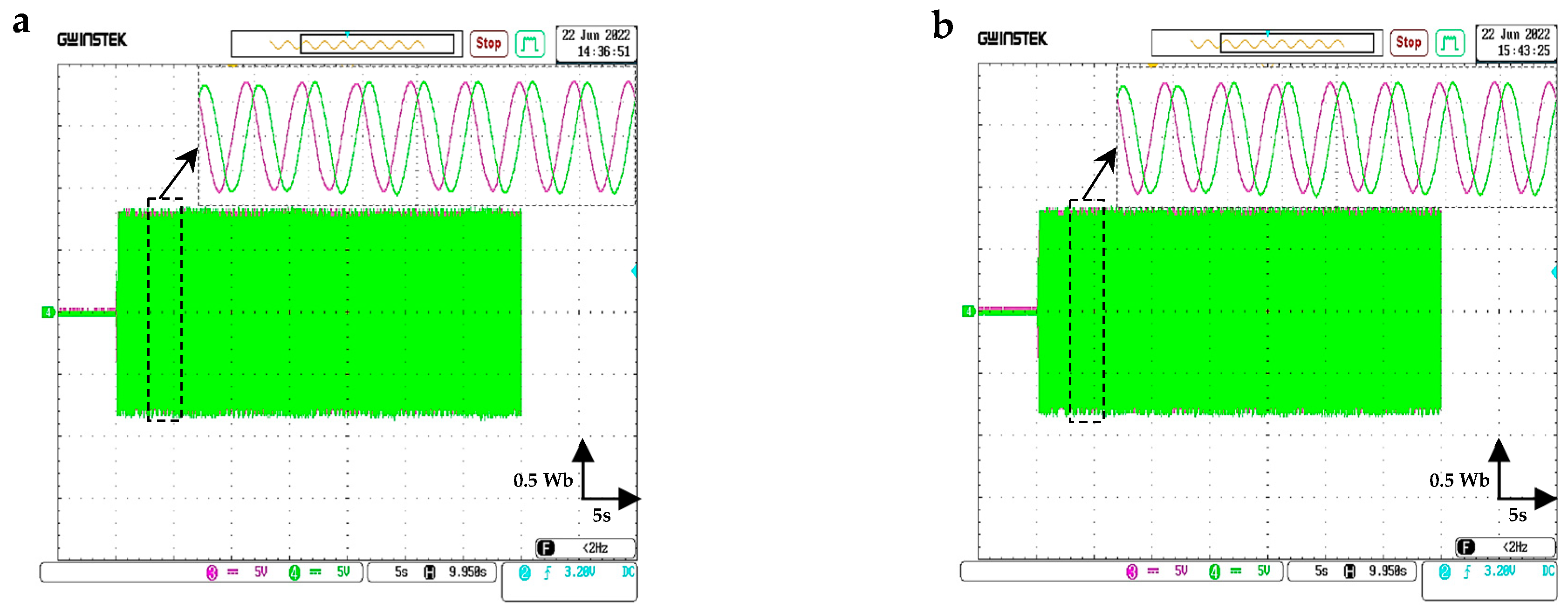
Figure 17, Figure 18, Figure 19, Figure 20, Figure 21, Figure 22, Figure 23 and Figure 24 present, respectively, rotor speed response, electromagnetic torque, stator phase current, rotor flux magnitude, rotor flux components, and estimation load torque. The figures are specified as (a) for the first trajectory speed profile and (b) for the speed profile of the second trajectory. During vehicle navigation, the acting resistive forces on the vehicle motion must be considered. The applied resistive forces are the rolling force, the aerodynamic drag force, the climbing force, and the acceleration force. Therefore, an electric vehicle with speed v , mass m , and an inclined plane with slope angle δ will be considered by selecting different scenarios of load torque to emulate real-life driving situations.
The results given in Figure 17 and Figure 18 show clearly that the rotor speed tracks the speed profiles perfectly through the whole trajectory with good dynamics, without overshoot, and with a fast manner of response of the electromagnetic torque that follows its reference depending on the speed variation.
Figure 19 and Figure 20 show zooms of Figure 18 with a focus on the periods that demonstrate an increase in the applied load. From these figures, it is remarkable that the speed error is almost negligible due to the use of the proposed back-stepping approach that works to compensate for the speed error caused by the applied load torque rapidly.
Figure 21 shows the stator phase current with zooms. The current shape has a smooth waveform and low harmonics. It is worth noting that integrating the SVM strategy with the back-stepping technique considerably reduces the chattering phenomenon.
The flux magnitude and components are shown in Figure 22 and Figure 23, respectively. The magnitude has a fast response, low ripples, and good tracking performance around the reference (0.8 Wb). The waveforms of the flux are very smooth with low harmonics.
Figure 24 shows the estimated load torque. It is clear that the designed back-stepping observer responds quickly to load variation. The estimated load torque has an accurate change without any fluctuation. The observed steps at the intervals (16.4 s to 17.7 s) and (32.3 s to 33.8 s) for trajectory 1 and the intervals (18.1 s to 19.3 s) and (31.1 s to 32 s) for trajectory 2 are estimated due to increases in the applied load during these intervals.
From the results of our study, it is evident that the implementation of our proposed speed planning algorithm and back-stepping approach can bring about a multitude of benefits and advantages. These benefits were carefully evaluated, and the results are summarized in Table 3.

6. Conclusions

This paper presents a novel approach to enhancing the performance of AEV navigation along a predetermined trajectory. To achieve this goal, the paper proposes the use of an SPA that generates an ideal speed profile based on the principal characteristics of the trajectory. The generated speed profile is then utilized as a reference to control the speed of the IM, which functions as the traction component of the electric vehicle. To accomplish this, a back-stepping approach with a space vector modulation strategy was proposed.
The results obtained from implementing the SPA highlight the significance of this technique in improving the safety and comfort of passengers during AEV navigation. The SPA enables the selection of an appropriate speed for the vehicle while ensuring a smooth transition between acceleration, deceleration, and steady-state operation. By doing so, the SPA effectively reduces the impact of abrupt speed changes, minimizing potential discomfort for passengers. These findings underscore the importance of the SPA as an essential tool for designing efficient and passenger-friendly AEV navigation systems. The experimental results obtained from the back-stepping approach application to the IM demonstrate the exceptional tracking performance of the reference speed and the system’s rapid response against external load disturbances, validating the robustness and effectiveness of the proposed control technique. Furthermore, incorporating the SVM strategy not only provides a smooth shape to the current waveform, but it also reduces the undesirable torque ripples that can occur during operation. These impressive results highlight the efficacy of the proposed control strategy, demonstrating its potential as a reliable and efficient solution for controlling the IM in AEVs. Combining these two methods yields a potent and dependable speed control approach that significantly improves the accuracy and robustness of AEV speed control and is anticipated to have a wide range of uses in the electric vehicle industry.

7. Future Work

In the field of intelligent vehicle navigation, the potential for advancements is boundless. As we look towards the future, one promising area of exploration involves the integration of path geometry with intelligent algorithms, utilizing data on the driver’s preferred speed. With this combination, vehicles can make more informed decisions, allowing for optimal performance and efficiency. Additionally, incorporating real-time traffic data can provide a previously unseen opportunity for autonomous electric vehicle navigation to reach new heights. By harnessing this data, self-driving cars can make informed decisions and adjust their routes in real-time, resulting in more efficient and timely transportation for all. Furthermore, by factoring in the position of other vehicles, these automobiles can effortlessly adapt their speed while traversing urban environments, thereby enhancing safety and creating a more seamless experience for all. The possibilities for advancing intelligent vehicle navigation are boundless, and the day when these technologies are widely available for all to benefit from is eagerly anticipated.

Author Contributions

Conceptualization, S.B. and R.S.; Methodology, S.B., R.S., M.Y.A., M.S., K.L. and A.J.M.C.; Software, S.B. and R.S.; Validation, S.B., R.S. and M.Y.A.; Formal analysis, S.B., R.S., M.Y.A., M.S. and K.L.; Investigation, S.B. and R.S.; Resources, A.J.M.C.; Writing—original draft, S.B.; Writing—review & editing, R.S., M.Y.A., M.S., K.L. and A.J.M.C.; Visualization, S.B. and R.S.; Supervision, R.S., M.Y.A., M.S. and A.J.M.C.; Project administration, A.J.M.C.; Funding acquisition, A.J.M.C. All authors have read and agreed to the published version of the manuscript.

Funding

This work was supported by the Portuguese Foundation for Science and Technology (FCT) under Projects UIDB/04131/2020 and UIDP/04131/2020.

Data Availability Statement

Not applicable.

Conflicts of Interest

The authors declare no conflict of interest.

References

  1. Kumar, R.R.; Alok, K. Adoption of electric vehicle: A literature review and prospects for sustainability. J. Clean Prod. 2020, 253, 119911. [Google Scholar] [CrossRef]
  2. Li, Z.; Khajepour, A.; Song, J. A comprehensive review of the key technologies for pure electric vehicles. Energy 2019, 182, 824–839. [Google Scholar] [CrossRef]
  3. İnci, M.; Büyük, M.; Demir, M.H.; İlbey, G. A review and research on fuel cell electric vehicles: Topologies, power electronic converters, energy management methods, technical challenges, marketing and future aspects. Renew. Sustain. Energy Rev. 2021, 137, 110648. [Google Scholar] [CrossRef]
  4. Karki, A.; Phuyal, S.; Tuladhar, D.; Basnet, S.; Shrestha, B.P. Status of pure electric vehicle power train technology and future prospects. Appl. Syst. Innov. 2020, 3, 35. [Google Scholar] [CrossRef]
  5. Lai, F.; Carsten, O.; Tate, F. How much benefit does Intelligent Speed Adaptation deliver: An analysis of its potential contribution to safety and environment. Accid. Anal. Prev. 2012, 48, 63–72. [Google Scholar] [CrossRef] [PubMed]
  6. Lai, F.; Carsten, O. What benefit does Intelligent Speed Adaptation deliver: A close examination of its effect on vehicle speeds. Accid. Anal. Prev. 2012, 48, 4–9. [Google Scholar] [CrossRef] [PubMed]
  7. Aguil-Éra, V.; Glaser, S. Data Requirements for Enhanced Digital Maps in an Advanced Curve-Speed Warning System. Transp. Res. Rec. J. Transp. Res. Board 2004, 1886, 109–118. [Google Scholar] [CrossRef]
  8. Glaser, S.; Nouvelire, L.; Lusetti, B. Speed limitation based on an advanced curve warning system. In Proceedings of the 2007 IEEE Intelligent Vehicles Symposium, Istanbul, Turkey, 13–15 June 2007; pp. 686–691. [Google Scholar]
  9. Funk, J.; Wirth, J.; Bonugli, E.; Watson, R. An Integrated Model of Rolling and Sliding in Rollover Crashes; SAE Technical Paper; SAE International: Warrendale, PA, USA, 2012. [Google Scholar]
  10. Pratt, M.P.; Geedipally, S.R. Developing a framework for evaluating and selecting curve safety treatments. In Proceedings of the Transportation Research Board 95th Annual Meeting, Washington, DC, USA, 10–14 January 2016. [Google Scholar]
  11. Roy, S.; Pandey, R. A Review on Motor and Drive System for Electric Vehicle. In Planning of Hybrid Renewable Energy Systems, Electric Vehicles and Microgrid: Modeling, Control and Optimization; Springer: Singapore, 2022; pp. 601–628. [Google Scholar]
  12. De Klerk, M.L.; Saha, A.K. A comprehensive review of advanced traction motor control techniques suitable for electric vehicle applications. IEEE Access 2021, 9, 125080–125108. [Google Scholar] [CrossRef]
  13. Men, X.; Guo, Y.; Wu, G.; Chen, S.; Shi, C. Implementation of an Improved Motor Control for Electric Vehicles. Energies 2022, 15, 4833. [Google Scholar] [CrossRef]
  14. Wang, F.; Zhang, Z.; Mei, X.; Rodríguez, J.; Kennel, R. Advanced Control Strategies of Induction Machine: Field Oriented Control, Direct Torque Control and Model Predictive Control. Energies 2018, 11, 120. [Google Scholar] [CrossRef] [Green Version]
  15. El Ouanjli, N.; Derouich, A.; el Ghzizal, A.; Chebabhi, A.; Taoussi, M. A comparative study between FOC and DTC control of the Doubly Fed Induction Motor (DFIM). In Proceedings of the 2017 International Conference on Electrical and Information Technologies ICEIT, Rabat, Morocco, 15–18 November 2017; pp. 1–6. [Google Scholar]
  16. Chinthakunta, U.R.; Prabhakar, K.K.; Singh, A.K.; Kumar, P. Direct torque control induction motor drive performance evaluation based on torque error status selection methods. IET Electr. Syst. Transp. 2019, 9, 113–127. [Google Scholar] [CrossRef]
  17. Taïb, N.; Metidji, B.; Rekioua, T. A fixed switching frequency direct torque control strategy for induction motor drives using indirect matrix converter. Arab. J. Sci. Eng. 2014, 39, 2001–2011. [Google Scholar] [CrossRef]
  18. Farajpour, Y.; Alzayed, M.; Chaoui, H.; Kelouwani, S. A Novel Switching Table for a Modified Three-Level Inverter-Fed DTC Drive with Torque and Flux Ripple Minimization. Energies 2020, 13, 4646. [Google Scholar] [CrossRef]
  19. Costa, B.L.G.; Graciola, C.L.; Angélico, B.A.; Goedtel, A.; Castoldi, M.F.; de Andrade Pereira, W.C. A practical framework for tuning DTC-SVM drive of three-phase induction motors. Control Eng. Pract. 2019, 88, 119–127. [Google Scholar] [CrossRef]
  20. Zahraoui, Y.; Akherraz, M.; Fahassa, C.; Elbadaoui, S. Induction Motor DTC Performance Improvement by Reducing Flux and Torque Ripples in Low Speed. J. Robot. Control. (JRC) 2022, 3, 93–100. [Google Scholar] [CrossRef]
  21. Aktas, M.; Awaili, K.; Ehsani, M.; Arisoy, A. Direct torque control versus indirect field-oriented control of induction motors for electric vehicle applications. Eng. Sci. Technol. Int. J. 2020, 23, 1134–1143. [Google Scholar] [CrossRef]
  22. Solea, R.; Nunes, U. Trajectory planning and sliding-mode control based trajectory-tracking for cybercars. Integr. Comput. Aided Eng. 2007, 14, 33–47. [Google Scholar] [CrossRef]
  23. Bacha, S.; Saadi, R.; Ayad, M.-Y.; Aboubou, A. Speed-planning algorithm and super twisting control for autonomous vehicle steering system. Bull. Electr. Eng. Inform. 2023, 12, 109–120. [Google Scholar] [CrossRef]
  24. Lee, J.; Prabhuswamy, S. A Unified Framework of Adaptive Cruise Control for Speed Limit Follower and Curve Speed Control Function; SAE Technical Paper; SAE International: Warrendale, PA, USA, 2013. [Google Scholar]
  25. García, A.; Camacho-Torregrosa, F.J.; Baez, P.V.P. Examining the effect of road horizontal alignment on the speed of semi-automated vehicles. Accid. Anal. Prev. 2020, 146, 105732. [Google Scholar] [CrossRef]
  26. Deng, Z.; Chu, D.; Wu, C.; He, Y.; Cui, J. Curve safe speed model considering driving style based on driver behaviour questionnaire. Transp. Res. Part F Traffic Psychol. Behav. 2019, 65, 536–547. [Google Scholar] [CrossRef]
  27. Rosique, F.; Navarro, P.J.; Miller, L.; Salas, E. Autonomous Vehicle Dataset with Real Multi-Driver Scenes and Biometric Data. Sensors 2023, 23, 2009. [Google Scholar] [CrossRef] [PubMed]
  28. Colombaroni, C.; Fusco, G.; Isaenko, N. Coherence analysis of road safe speed and driving behaviour from floating car data. IET Intell. Transp. Syst. 2020, 14, 985–992. [Google Scholar] [CrossRef]
  29. Malek, Y.N.; Najib, M.; Bakhouya, M.; Essaaidi, M. Multivariate deep learning approach for electric vehicle speed forecasting. Big Data Min. Anal. 2021, 4, 56–64. [Google Scholar] [CrossRef]
  30. Park, J.; Murphey, Y.L.; McGee, R.; Kristinsson, J.G.; Kuang, M.L.; Phillips, A.M. Intelligent trip modeling for the prediction of an origin–destination traveling speed profile. IEEE Trans. Intell. Transp. Syst. 2014, 15, 1039–1053. [Google Scholar] [CrossRef]
  31. Jiang, B.; Fei, Y. Vehicle speed prediction by two-level data driven models in vehicular networks. IEEE Trans. Intell. Transp. Syst. 2016, 18, 1793–1801. [Google Scholar] [CrossRef]
  32. El-Sousy, F.F.M.; Amin, M.M.; Mohammed, O.A. Robust adaptive neural network tracking control with optimized super-twisting sliding-mode technique for induction motor drive system. IEEE Trans. Ind. Appl. 2022, 58, 4134–4157. [Google Scholar] [CrossRef]
  33. Ammar, A. Performance improvement of direct torque control for induction motor drive via fuzzy logic-feedback linearization: Simulation and experimental assessment. COMPEL-Int. J. Comput. Math. Electr. Electron. Eng. 2019, 38, 672–692. [Google Scholar] [CrossRef]
  34. Ammar, A.; Talbi, B.; Ameid, T.; Azzoug, Y.; Kerrache, A. Predictive direct torque control with reduced ripples for induction motor drive based on T-S fuzzy speed controller. Asian J. Control 2019, 21, 2155–2166. [Google Scholar] [CrossRef]
  35. Dan, H.; Zeng, P.; Xiong, W.; Wen, M.; Su, M.; Rivera, M. Model predictive control-based direct torque control for matrix converter-fed induction motor with reduced torque ripple. CES Trans. Electr. Mach. Syst. 2021, 5, 90–99. [Google Scholar] [CrossRef]
  36. Maidana, P.; Medina, C.; Rodas, J.; Maqueda, E.; Gregor, R.; Wheeler, P. Sliding-Mode Current Control with Exponential Reaching Law for a Three-Phase Induction Machine Fed by a Direct Matrix Converter. Energies 2022, 15, 8379. [Google Scholar] [CrossRef]
  37. Lascu, C.; Argeseanu, A.; Blaabjerg, F. Supertwisting sliding-mode direct torque and flux control of induction machine drives. IEEE Trans. Power Electron. 2019, 35, 5057–5065. [Google Scholar] [CrossRef]
  38. Ammar, A.; Kheldoun, A.; Metidji, B.; Ameid, T.; Azzoug, Y. Feedback linearization based sensorless direct torque control using stator flux MRAS-sliding mode observer for induction motor drive. ISA Trans. 2020, 98, 382–392. [Google Scholar] [CrossRef] [PubMed]
  39. Chen, C.; Yu, H. Backstepping sliding mode control of induction motor based on disturbance observer. IET Electr. Power Appl. 2020, 14, 2537–2546. [Google Scholar] [CrossRef]
  40. Li, Z.; Chitturi, M.; Bill, A.R.; Noyce, D.A. Automated identification and extraction of horizontal curve information from geographic information system roadway maps. Transp. Res. Rec. 2012, 2291, 80–92. [Google Scholar] [CrossRef] [Green Version]
  41. Luo, W.; Li, L. Automatic geometry measurement for curved ramps using inertial measurement unit and 3D LiDAR system. Autom Constr. 2018, 94, 214–232. [Google Scholar] [CrossRef]
  42. Gargoum, S.; El-Basyouny, K.; Sabbagh, J. Automated extraction of horizontal curve attributes using LiDAR data. Transp. Res. Rec. 2018, 2672, 98–106. [Google Scholar] [CrossRef]
  43. Park, M.; Lee, S.; Han, W. Development of steering control system for autonomous vehicle using geometry-based path tracking algorithm. Etri J. 2015, 37, 617–625. [Google Scholar] [CrossRef]
  44. Hancock, M.W.; Wright, B. A Policy on Geometric Design of Highways and Streets; American Association of State Highway and Transportation Officials: Washington, DC, USA, 2013. [Google Scholar]
  45. Ehsani, M.; Gao, Y.; Miller, J.M. Hybrid electric vehicles: Architecture and motor drives. Proc. IEEE 2007, 95, 719–728. [Google Scholar] [CrossRef]
  46. Zhu, Z.-Q.; Howe, D. Electrical machines and drives for electric, hybrid, and fuel cell vehicles. Proc. IEEE 2007, 95, 746–765. [Google Scholar] [CrossRef]
  47. Habetler, T.G.; Profumo, F.; Pastorelli, M.; Tolbert, L.M. Direct torque control of induction machines using space vector modulation. IEEE Trans. Ind. Appl. 1992, 28, 1045–1053. [Google Scholar] [CrossRef]
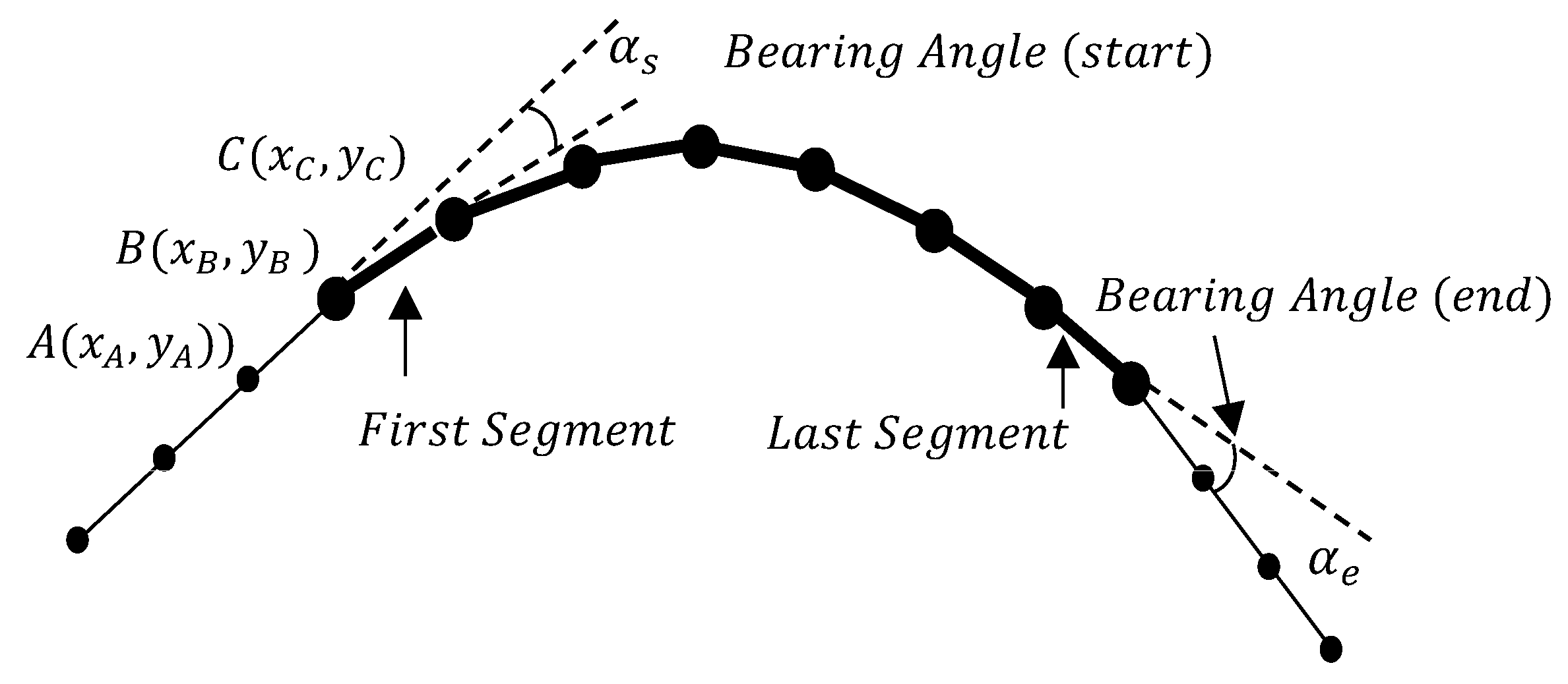
Figure 1. Bearing angle identification.
Energies 16 02459 g001
Figure 2. Curve parameters.
Energies 16 02459 g002
Figure 3. Forces applied on the vehicle.
Energies 16 02459 g003
Figure 4. Speed planning algorithm.
Energies 16 02459 g004
Figure 5. Overall diagram of vehicle speed control system.
Energies 16 02459 g005
Figure 6. Diagram of voltage space vector.
Energies 16 02459 g006
Figure 7. IM back-stepping control scheme.
Energies 16 02459 g007
Figure 8. Vehicle tracking trajectories.
Energies 16 02459 g008
Figure 9. Vehicle speed profiles.
Energies 16 02459 g009
Figure 10. IM speed profiles.
Energies 16 02459 g010
Figure 11. Response of speed under load during startup and steady state.
Energies 16 02459 g011
Figure 12. Electromagnetic torque under load during startup and steady state.
Energies 16 02459 g012
Figure 13. Stator phase current under load during startup and steady state.
Energies 16 02459 g013
Figure 14. Flux magnitude under load during startup and steady state.
Energies 16 02459 g014
Figure 15. Flux components under load during startup and steady state.
Energies 16 02459 g015
Figure 16. Experimental setup.
Energies 16 02459 g016
Figure 17. Speed response for speed profile 1 and 2.
Energies 16 02459 g017
Figure 18. Electromagnetic torque and speed response for speed profile 1 and 2.
Energies 16 02459 g018
Figure 19. Zoom 1 of electromagnetic torque and speed response for speed profile 1 and 2.
Energies 16 02459 g019
Figure 20. Zoom 2 of electromagnetic torque and speed response for speed profile 1 and 2.
Energies 16 02459 g020
Figure 21. Stator phase current for speed profile 1 and 2.
Energies 16 02459 g021
Figure 22. Rotor flux magnitude for speed profile 1 and 2.
Energies 16 02459 g022
Figure 23. Rotor flux components for speed profile 1 and 2.
Energies 16 02459 g023
Figure 24. Estimated load torque for speed profile 1 and 2.
Energies 16 02459 g024
Table 1. Parameters of navigation.
ParameterValue
Initial position s i = 0   Km
Final position s f = 592   m & s f = 557   m
Initial speed v i = 0   Km / h
Max. speed v m = 70   Km / h
Longitudinal acc. a = 8   m / s 2
Table 2. Parameters of the induction motor.
ParametersValue
Power P = 3   kW
Frequency F = 50   Hz
Stator resistance R s = 1.8   Ω
Rotor resistance R r = 2.45   Ω
Stator inductance L s = 0.268   H
Rotor inductance L r = 0.268   H
Mutual inductance L m = 0.257   H
Friction coefficient f = 0.00014   N · m · s / rad
Total inertia J = 0.02   kg · m 2
Pole pairs p = 2
Table 3. Benefits of speed planning algorithm and back-stepping approach.
BenefitsDescription
AdaptabilityAbility to adapt speed to changing roads and curvature
SafetyDriving over straight and curving stretches at safe speeds
ComfortabilityEnsuring smooth speed changes to respect passenger comfort
VersatilityApplicable to different types of vehicles
EfficiencyFast tracking of the reference speed with high accuracy and low error
RobustnessThe system’s ability to quickly respond to external load disturbances.
Disclaimer/Publisher’s Note: The statements, opinions and data contained in all publications are solely those of the individual author(s) and contributor(s) and not of MDPI and/or the editor(s). MDPI and/or the editor(s) disclaim responsibility for any injury to people or property resulting from any ideas, methods, instructions or products referred to in the content.