Next Article in Journal
Thermohydraulic and Economic Evaluation of a New Design for Printed Circuit Heat Exchangers in Supercritical CO2 Brayton Cycle
Next Article in Special Issue
Russian Arctic Mineral Resources Sustainable Development in the Context of Energy Transition, ESG Agenda and Geopolitical Tensions
Previous Article in Journal
Thermal Behavior and Kinetics of Shenmu Coal Pyrolyzed under Hydrogen-Rich or Methane-Gas-Rich Atmosphere
 
 
Retraction published on 19 July 2024, see Energies 2024, 17(14), 3542.
Article

RETRACTED: Investigation and Evaluation of the Hybrid System of Energy Storage for Renewable Energies

by
Abeer Abdullah Al Anazi
1,
Luis Andres Barboza-Arenas
2,*,
Rosario Mireya Romero-Parra
3,
Ramaswamy Sivaraman
4,
Maytham T. Qasim
5,
Sara Hakem Al-Khafaji
6,
Maher Abdulfadhil Gatea
7,
Reza Alayi
8,
Waqas Farooq
9,
Michał Jasiński
10,11,
Zbigniew Leonowicz
10,11,*,
Filip Novak
11 and
Radomir Gono
11
1
Department of Mechanical Engineering, Australian University (AU), Kuwait 1411, Kuwait
2
Department of Education, Technological University of Peru, Lima 15046, Peru
3
Department of General Studies, Universidad Continental, Lima 15046, Peru
4
Department of Mathematics, Dwaraka Doss Goverdhan Doss Vaishnav College, Arumbakkam, University of Madras, Chennai 600005, India
5
Department of Anesthesia, College of Health and Medical Technololgy, Al-Ayen University, Thi-Qar 64011, Iraq
6
Department of Media, Al-Mustaqbal University College, Babylon 51001, Iraq
7
Technical Engineering Department, College of Technical Engineering, The Islamic University, Najaf 54001, Iraq
8
Department of Mechanical Engineering, Germi Branch, Islamic Azad University, Germi 1477893855, Iran
9
Department of Electrical Engineering, Sarhad University of Science and Information Technology, Peshawar 25000, Pakistan
10
Department of Electrical Engineering, Wroclaw University of Science and Technology, 50-370 Wroclaw, Poland
11
Department of Electrical Power Engineering, Faculty of Electrical Engineering and Computer Science, VSB-Technical University of Ostrava, 708-00 Ostrava, Czech Republic
*
Authors to whom correspondence should be addressed.
Energies 2023, 16(5), 2337; https://doi.org/10.3390/en16052337
Submission received: 26 January 2023 / Revised: 17 February 2023 / Accepted: 24 February 2023 / Published: 28 February 2023 / Retracted: 19 July 2024

Abstract

:
The system presented in this paper can change the energy storage landscape by having the advantages of a compressed air storage system and pump storage, as well as minimizing the disadvantages of these two systems. One of the advantages of this system compared to similar systems is the lack of combustion of natural gas. Correspondingly, for construction, it does not require specific specifications for the executive site, and control of the energy and heat of the system (due to the use of water as an operational fluid) is easier than similar systems. In addition, this system is very scalable and can be designed in low capacities to high capacities, energy analysis of this research to identify the basic and effective parameters of the system and determine the limitations and relationships between them. The amount of energy saved in the current research system compared to previous research is significant, and 92% efficiency can be achieved. The energy analysis of this research determined the effect of the parameters on each other and their limitations so that the path of its feasibility design was paved.

1. Introduction

The ever-increasing growth of the world’s population and the continuous increase in energy consumption, in addition to numerous environmental consequences, have caused the sustainable supply of energy to face a challenge. The use of renewable energy systems can be a suitable solution to all these problems, but due to the unstable nature of renewable energy sources, and because power grid operators do not have much control over the amount of energy consumption [1], the development of the use of renewable energy sources requires energy storage systems.
According to the technology used in energy storage systems, they can be divided into five categories: thermal, mechanical, electrochemical, electrical, and chemical [2]. Compressed air and pump hydroelectric storage systems are part of mechanical energy storage systems that, in terms of power, the duration of energy storage and the lifetime of the system are the highest, and their construction and maintenance costs are lower than other energy storage systems [3]. The storage pump system requires a specific site for construction, and construction is not possible in every region and with every scale [4]. Moreover, common storage pump systems have adverse effects on the environment, and due to the high volume of evaporation, the use of freshwater sources in them is not economical [5]. In addition, the compressed air energy storage system has disadvantages; among them, we can mention fossil fuel consumption in the conventional compressed air energy storage system and the need for large underground caves for compressed air storage, which causes many limitations for the widespread use of this system [6].
In recent years, numerous types of research have been conducted in the field of compressed air energy storage systems and conventional compressed air energy storage systems using a combination of different technologies [7]. Among the applied solutions, heat storage at low temperatures [8,9], combining a compressed air energy storage system with a photovoltaic power plant and a city gas pressure reducing station [10], and integrating a wind farm with a compressed air energy storage system and flywheel can be mentioned [11].
Other new solutions have been presented to improve the compressed air energy storage system, one of which is the new supercritical compressed air energy storage system [12]. This system does not require fossil fuel combustion and compressed air storage cave and has a higher efficiency than conventional systems [13]; this system works based on air liquefaction. Guizi et al. [14] also showed that analyzing the energy of this system has a high potential for use with renewable energy systems because air liquefaction increases the energy density stored in the system and is about 18 times more common than compressed air energy storage systems [12]. Xie et al. [15] evaluated the feasibility of this system in England, and their research results indicated the applicability of this system. Ferrers-Antonius et al. [16], in a study thermodynamically analyzed the performance of this system together with the heat pump, showed that the efficiency of the combined system is higher than the efficiency of the heat pump and the energy storage of the above-mentioned critical compressed air separately. Despite the advantages of air liquefaction, the efficiency of this system is lower than that of other modern combined systems and rarely reaches more than 60% [17,18,19].
Kim et al. [20] presented that the hydrostatic pressure of water or the pressure created by using a pump is used to keep the air pressure constant during discharge, so that the output energy of the system is stable. This type of system can be, first, the combined energy storage system called compressed air and storage pump. Wang et al. [21] designed and analyzed a multi-level underwater compressed air energy storage system in which compressed air is stored underwater in flexible tanks.
Klar et al. [22] found that this system is floating and is the same as the research system of Wang et al. [21], which is woven and flexible. In this system, compressed air is used to increase the head of the storage pump system.
Yao et al. [23] presented another type of combined energy storage system of compressed air and a storage pump, which is on land and does not require a lake or a special place for construction. The first effective patent in this field was carried out by Heidenreich [24] in 2007. This system does not need to burn fossil fuels, does not require a specific characteristic for the construction site, and is very scalable. In addition, the results of the energy analysis and evaluation of the new hybrid system energy storage in Yano et al.’s research [23] showed that the efficiency of the combined energy storage system of compressed air and a storage pump is higher than other similar systems.
Due to the newness of the combined compressed air energy storage system and storage pump compared to other similar combined systems, less research has been done in this field. The relationship between the main parameters of the system and the efficiency of the system under different operating conditions needs to be analyzed and investigated. In addition, there are two major problems in the systems investigated in the research background. First, the water output from the water turbine is transferred to a secondary tank, which has a permanent connection with the ambient air; in other words, it is an open tank. Thus, there is water evaporation in the system, and the value of the wasted water may be greater than the practical importance of the storage system. The second case refers to the air compression way in the systems investigated in the background of the research. In these systems, the compressor is only used to create an initial pressure, and the main air pressure is created by pumping water by the pump; therefore, the operating pressure of these systems depends on the power of the water pump, which is less than the power of existing compressors. In this article, a hybrid compressed air and storage pump energy storage system is provided in which, by using an air discharge mechanism, there is no permanent connection between the atmospheric air and the second tank during the system preparation stage for charging, so the amount of water evaporation reaches as low as possible. Likewise, by using the air discharge mechanism, the waste of a large part of the system’s energy is prevented. The capacity of this system is limited only by the technological limitations of air compression and compressed air storage equipment, and it has a higher capacity than previous systems. In this article, the energy flow of the system was analyzed, and the relationship between the main parameters of the system and each other, the limitations of the parameters, the amount of waste, and energy savings was evaluated in different operating conditions.
In this study, the case study system is a combination of energy storage systems of compressed air and a storage pump, which includes the motor and compressor of the high-pressure tank, the low-pressure tank of the water turbine, and the engine-generator pump and four flow control valves.

2. Materials and Methods

2.1. Description of the System

A schematic view of the presented system is displayed in Figure 1. This system is a combination of energy storage systems of compressed air and a storage pump, which include the motor and compressor of the high-pressure tank, the low-pressure tank of the water turbine, and the engine-generator pump and four flow control valves. The processes of this system can be divided into three stages: charging, discharging, and divided preparation. At the beginning of the cycle, all four control valves are closed.

2.1.1. Charging Stage

In Processes 1–2, the motor starts working with electric energy and moves the compressor. Simultaneously, the first faucet opens, and air with temperature and ambient is compressed by the compressor and stored in the high-pressure tank until it reaches the desired target pressure. Then, the engine and compressor are stopped, and faucet 1 is closed. The electric energy driving the engine is obtained from renewable energy plants or electricity produced during low-load hours. Electric energy is converted into mechanical potential energy.

2.1.2. Discharging Stage

Processes 3–4: faucets 2 and 3 are opened, high-pressure air sends incompressible fluid or water to the water turbine, and the water turbine produces electric power from the generator. The low-pressure tank is entered. The volume of this tank is only slightly greater than the volume of water entering it; thus, the mechanical potential energy is converted into electrical energy (the height difference between the tanks causes the blades of the water turbine to rotate, and electrical energy is produced).

2.1.3. Preparation Stage

Process 5–6: faucet 3 is closed and faucet 4 is opened; thus, the small air pressure in the low-pressure tank is equal to the residual air pressure in the high-pressure tank. This pressure is lower than the target pressure, but it causes less energy to be consumed in the next charging process.
Processes 3–4: With the equalization of the pressure of both tanks, the water pump easily transfers water from the low-pressure tank to the high-pressure tank by using the electric energy supplied to the motor. At the end of this process, faucet 4 is closed; thus, the system is ready for the charging process.
As mentioned, in the preparation stage, an air discharge mechanism has been developed to correct the residual pressure problem and the remaining energy stored in the tank after discharge. In this method, a secondary tank with a volume almost equal to the water volume of the high-pressure tank is used to collect water during discharge. Once the discharge is done, the pressure of both the high-pressure and low-pressure tanks will be balanced. Considering that the second tank contains very little air, the residual pressure will remain unchanged, and an ineffective pressure difference now exists between the tanks, and the water can be pumped from one to the other. The final result of this algorithm is that the main reservoir contains water and air with residual pressure, and the second reservoir contains only air with residual pressure. Then, the secondary tank is drained or used in the second process. In this study, it is assumed that it is drained, so the stored energy is still wasted, but only a fraction of the remaining energy in the tank is wasted. During the next cycle, the main tank is released from atmospheric pressure. It is not pressurized until the target pressure, but compression starts with residual pressure. To start again, the tank cycle must be filled with water to a certain height. This water-to-air ratio is an important parameter in system performance. The amount of water that the tank should initially hold is not necessarily an optimization problem, but its design considerations are important, according to the application. In this stage, the water is pumped into an empty tank so that the air is not compressed in this process.

2.2. Energy Analysis of the System

To analyze the combined energy storage system of compressed air and a storage pump, the following assumptions are considered:
  • The pressure and temperature of the environment are equal to 100 kPa and 298 °K;
  • Due to the adiabatic nature of the processes;
  • The heat losses and pressure drop in the pipes are negligible;
  • There is an insulated floating surface between water and air;
  • Heat transfer between them is negligible.

2.3. System Parameters in the First Circle

An important parameter of the system is the ratio of air to water in the uncharged high-pressure tank. To determine this characteristic, parameter α is the ratio of the initial volume of air to the final volume of air. Or the volume of air is defined as the total volume in the high-pressure tank, low values of α mean a large amount of initial water in the system, and large values mean a system with a very low amount of water. Thus, we have
α = V b V d
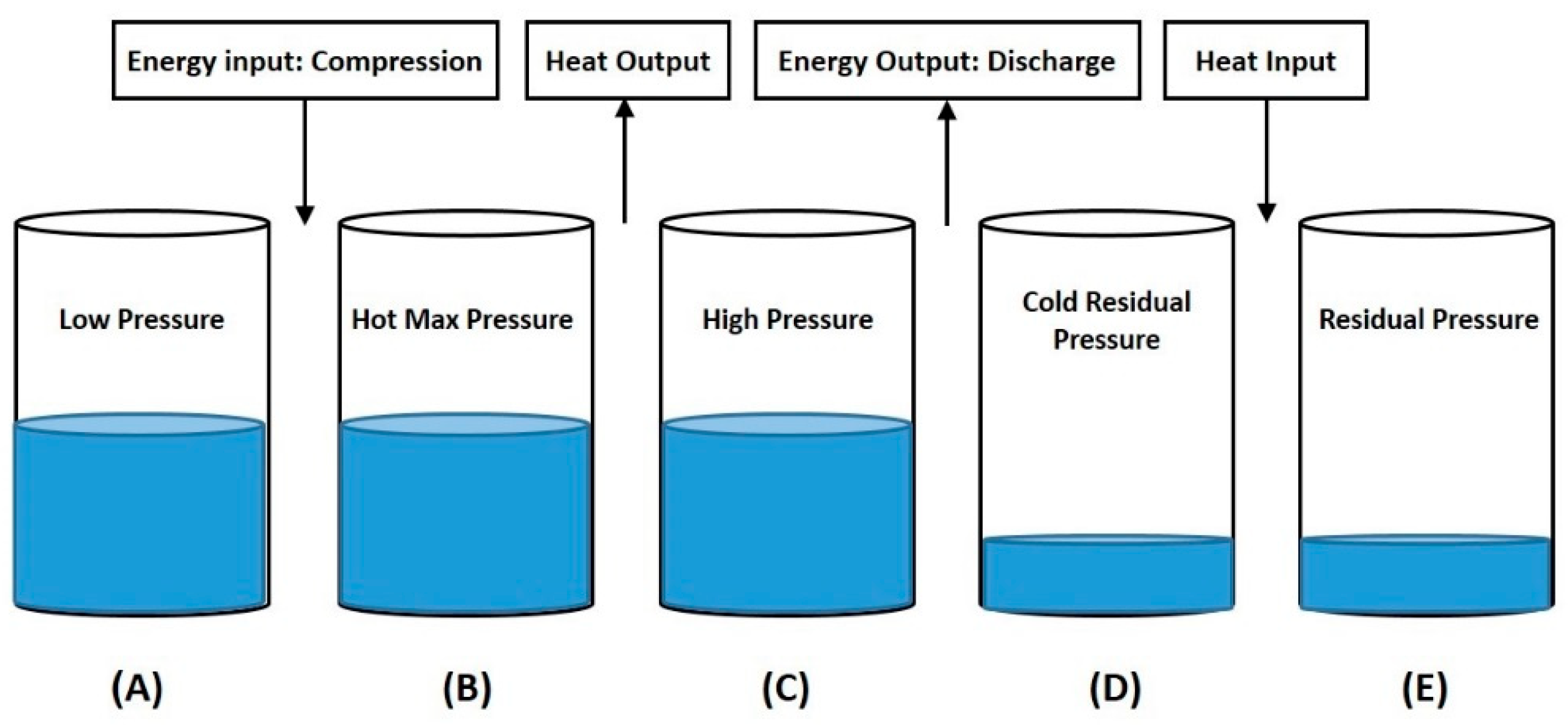
V is the volume of air and indices b and d respectively correspond to the environmental conditions before and after the expansion of the air in the high-pressure tank. When the tank is up to the ratio of the tank is filled with water, the compressor starts working and operates until it reaches the desired pressure, the amount of heat generated, and as a result, the mechanical potential lost is directly proportional to the pressure difference; therefore, it is beneficial to design a system that minimizes these losses. The different states of the high-pressure tank during the process are shown in Figure 2.
In state (a), initial pressure and temperature prevails, in state (b), maximum pressure and temperature prevails, and in state (c), maximum pressure prevails, but the high-pressure tank has lost heat. Then, in case (d), the residual pressure remains in the high-pressure tank, where the air temperature has dropped. Finally, the heat taken from the high-pressure tank in state (c) is returned to the tank again in step (2). Considering the mono-entropy of air compression and expansion processes [25]:
PV κ = constant
P b V b κ = P d V d κ
P is air pressure, V is air volume, and κ is polytrophic constant. Thus, the result is:
P d = P b α κ
Pd is the residual pressure and Pb is the maximum pressure of the system in the high-pressure tank or the target pressure. Therefore, the work input to the system is equal to the total energy difference between states a, and b:
P a ν a κ = P b ν b κ
ν is the specific volume, m is mass, and T is temperature. By placing the definition of total internal energy [25,26]:
U = mC v T
Cv is the specific heat capacity of the air in a constant volume. The total internal energy in the state can be shown as follows:
U b = U a m b m a κ = U a α κ
And changes in the total internal energy during compression at constant volume are equal to:
Δ U a b = U a α κ 1
During the next two states (b) to (c), the mass of air in a fixed volume exchanges excess heat with the environment. The internal energy becomes [26,27]:
U c = m c C v T c
m c = m b ,   T c = T a
U c = m c C v T c = U a m b m a = U a α 1
And changes in total internal energy during heat loss in mass and volume are constant [27,28]:
Δ U b c = U a α κ α 1
Therefore, the amount of the input energy that is converted into heat ( γ ) is obtained from the ratio of Equation (14) to Equation (10) [27,28]:
γ = Δ U b c Δ U a b = U a α κ α 1 U a α κ 1
γ = 1 α κ 1 1 α κ
The internal energy in the state is a function of the initial internal energy [26]:
U c = U a α 1
In the d:
U d = U a α κ 2
The ratio of stored energy to the energy remaining in the reservoir after expansion ( δ ) is obtained from the ratio of Equation (17):
δ = U d U c = U a α κ 2 U a α 1 = α κ 2 α 1 = α κ 1
To obtain the ratio of energy remaining in the reservoir to input work (2) despite the heat loss after compression is obtained by using the equations:
μ = U d Δ U a b = α κ 2 α κ 1

2.4. System Parameters in the Closed State

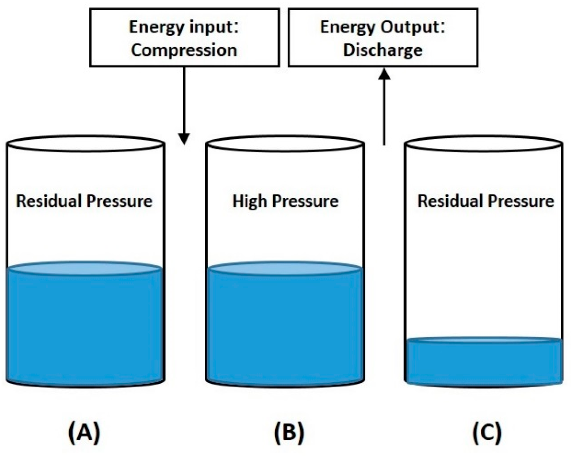
In an ideal closed system, the output energy of the system can be determined from the change in internal energy during expansion. Therefore, according to the repetition of the process in several cycles, the initial pressure of the system can be assumed as the residual pressure. By removing the steps of taking heat and returning it to the system, state (a) is the residual pressure, state (b) is the maximum pressure, and state (c) is the residual pressure in the tank, as specified in Figure 3.
The reason for starting the system in the next cycles with residual pressure is the recovery of a significant part of the energy is in the preparation stage, which is done by equalizing the pressure of the two high-pressure and low-pressure tanks by the air discharge mechanism. The output work is the change in the internal energy from state (b) to (c):
W out = U b U c = m b C v T b m c C v T c
W out = C v R P b V b P c V c = C v R α P b V c P c V c = C v R α P b V c α κ P b V c
W out = C v R P b V c α α κ
R is the universal gas constant. Similarly, the input energy to the system is obtained by integrating the specific volume over pressure changes (28):
W m = P a P b vdP ,   W = m P a P b vdP ,
Once again assuming mono-entropy of compression:
P a = P c = P b α κ
By placing these equations and integrating the input work into the system with the assumption explained as a function of e:
W in = C v R P b V c α α κ + 1
According to Equations (7), (15) and (16), the ratio of internal energy in all three states is shown as follows:
U a = U c α κ
U b = U c α 1 κ
Therefore, the input and output work of the system can be given as follows:
Δ U a b = U c α 1 κ α
Δ U b c = U c α 1 κ 1
Similarly to Equation (17), the ratio of energy remaining in the tank after discharge to stored energy becomes ( δ ):
δ = U c U b = 1 α 1 κ = α κ 1
The amount of the remaining energy in the tank compared to the input work (µ) without heat loss is equal to:
μ = U c Δ U a b = α κ 1 α 1
Just as the input and output energy is a function of α, the efficiency of this system is also a function of α. Assuming heat recovery during the compression/expansion process and the ideal performance of the components, the inefficiency of the system is only the result of discharge losses. Therefore, the efficiency (η) of this system can be determined from the following equation:
η = W out W in = C v R P b V c α α κ C v R P b V c α α κ + 1
η = α α κ α α κ + 1
According to the analysis, wasted energy is equal to:
Δ U a c = U a U c = U c 1 α
So the ratio of energy loss to residual energy is shown as follows:
Δ U a c U c = 1 α
To analyze the effectiveness of the preparation stage and pressure equalization of two high-pressure and low-pressure tanks or the air discharge mechanism, using Equations (24) and (27):
Input   work   with   residual   pressure   input   work   at   atmospheric   pressure = α κ 1 α κ 1 0.1 P b
Therefore, for the ratio of the energy saved using the air discharge mechanism to the input energy without the air discharge mechanism (λ):
λ = 1 α κ 1 α κ 1 0.1 P b

3. Results

3.1. Validation

To validate the results of this research, the model presented using the research data of Vila et al. [29] was compared with the main data of this research (Figure 4). In this analysis, the residual pressure is equal to the atmospheric pressure (0.101 MPa), and the volume of the tank is 1 m3. The pressure for a constant and isothermal system in a volume of 0.01 m3 is equal to 63.7 and 10.1 MPa, respectively, and in a volume of 0.1 m3, it is equal to 2.5 and 1.01 MPa along α. The air volume in this figure shows the same amount of the process because the volume of the tank is 1 m3. As is clear in Figure 4, for the process of adiabatic, the highest output energy is 1341 kJ, and for isothermal, it is 500 kJ. The work done at 0.1 m3 for the open and isothermal states is 358 and 223 kJ, respectively. The amount of work done in the open state is completely consistent and the same for both systems (Villa et al. [29] and the presented system).
The difference between the current research system and the research system of Villela et al. is in the current research, the main work is done by the compressor, while in the previous research, a cylinder-piston system was used. In previous research, the water is between the air and the piston, and work is produced by direct air propulsion, while in the current research, energy storage is achieved by air compression, and work is produced by water thrust. Additionally, the current research system is scalable, and an air evacuation mechanism is used in it, which is not the case in previous research. To further examine the results of the analyses performed, the results of the present study were compared with the results of the study by Ng et al. [30].
The difference between the present research and the research of Ng et al. is in the air compression method. In their research, Wang et al. used a water pump to compress air, while the current research system uses a compressor to compress air, which increases operating pressure and energy storage capacity. The air discharge mechanism is used in the current research system. In addition, Wang et al. assumed the system to be isothermal, while the system in the present research is non-thermal. In the study of Wong et al., instead of α, the ratio of the volume of water to the air inside the tank ( ϵ ) was used, so for accuracy, it is necessary to determine the relationship between α and ϵ , which is shown in Equation (37), and accuracy modeling the measurement was carried out using the mathematical model of the current research and according to the equation:
α = 1 1 + ε
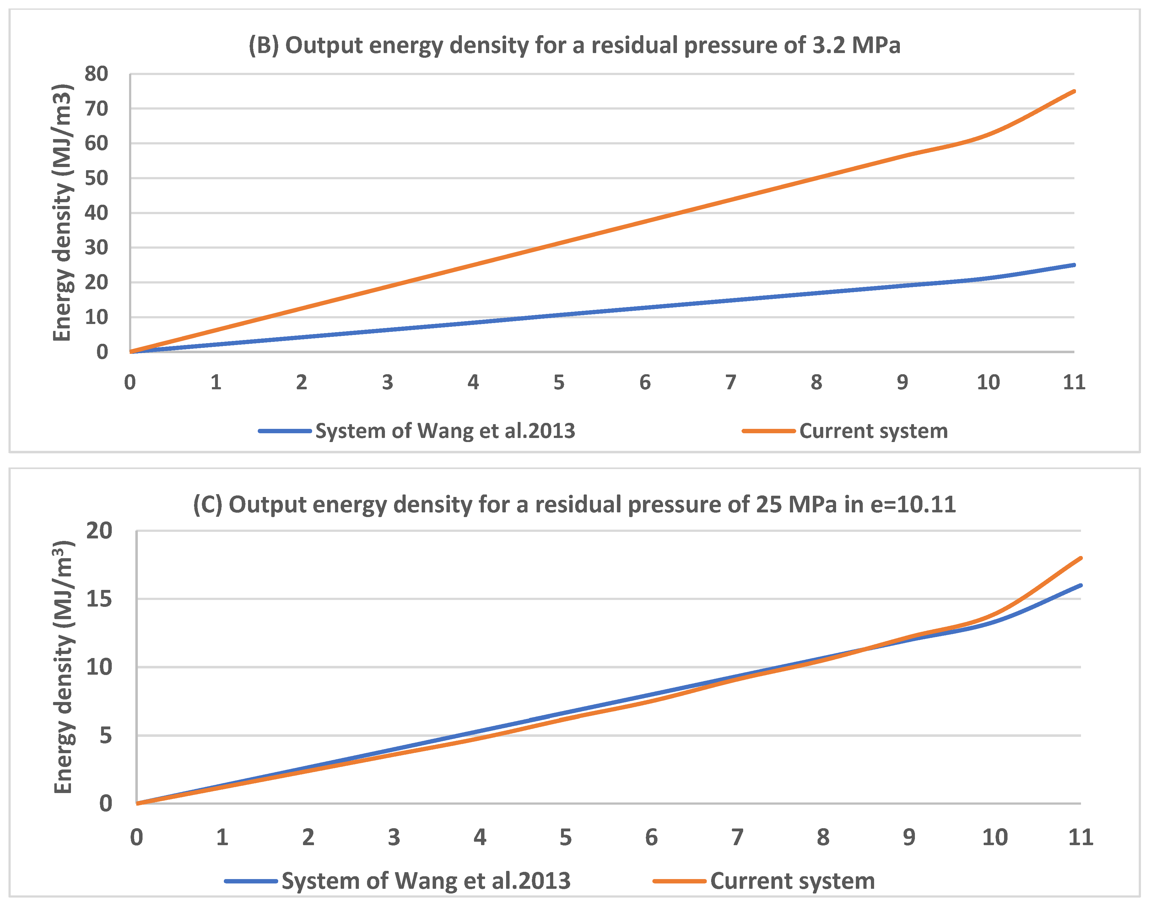
Figure 5 shows the residual pressure of both systems in isothermal and non-isothermal states is assumed to equal 2.5 MPa according to Wang et al.’s research and in diagram (B) the residual pressure of both systems is presented as Under the maximum pressure, it is 25 MPa (87.2) MPa, but in diagram (C), it is assumed that the pressure of both systems is equal to 25 MPa according to the research of Wang et al. at the point −11.10, so the residual pressure of the two systems will be different. The residual pressure for Wang et al.’s system and the system presented in diagram (C) of Figure 5 is equal to 2.5 and 0.687 MPa, respectively. Figure 6 shows the results of the studied system compared to Wang et al.’s [30] system, taking pressure changes into account.
The efficiency of both systems is considered to be 92%, according to Wang et al.’s research; the energy density for the steady state (the system presented in the present article) is higher than that of isothermal, and their difference is consistent with Figure 4. The energy density of the system in isothermal conditions with a residual pressure of 3.2 MPa is consistent with the energy density of Wang et al.’s research. The validity check shows the logical and correct performance of the mathematical model of the system and the accuracy of the results of this research.

3.2. The Effect of the Air Discharge Mechanism

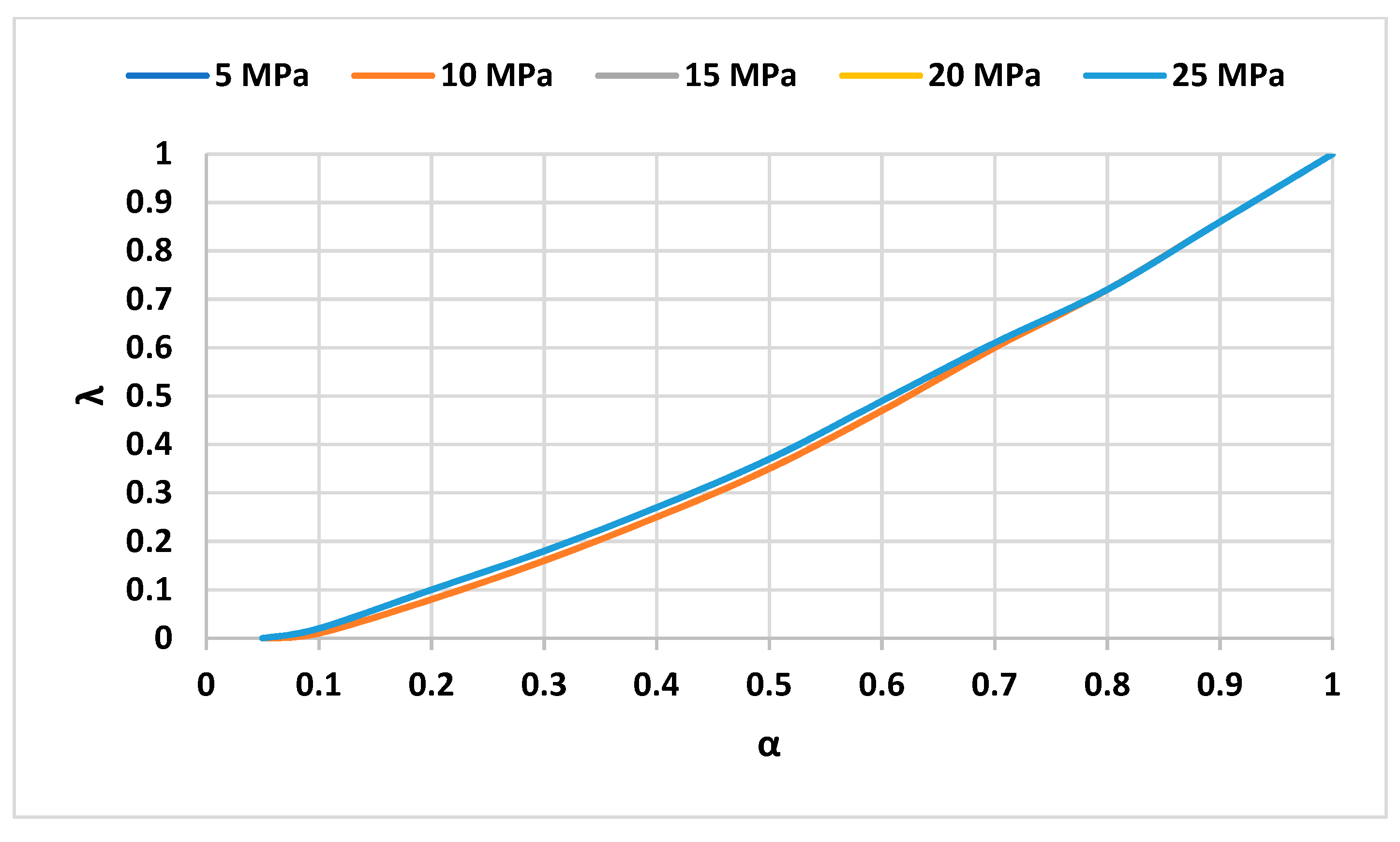
One advantage of the air discharge mechanism is that in the next cycle, the tank starts working with compressed air (residual pressure). First, the system cycle always goes through a cycle between high pressure and residual pressure, and there is never a need to empty the atmosphere of the high-pressure tank. The remaining in the tank after the expansion is the same in both cases, with and without heat loss, to check the amount of energy saved using the ratio. According to the research of Yao et al. [23] and Bei et al. [31], the design pressure or the maximum air pressure in the system is assumed to be between 5 and 25 MPa. In this way, it is possible to check the effect of changes in each design pressure on the amount of energy saved (Figure 7).
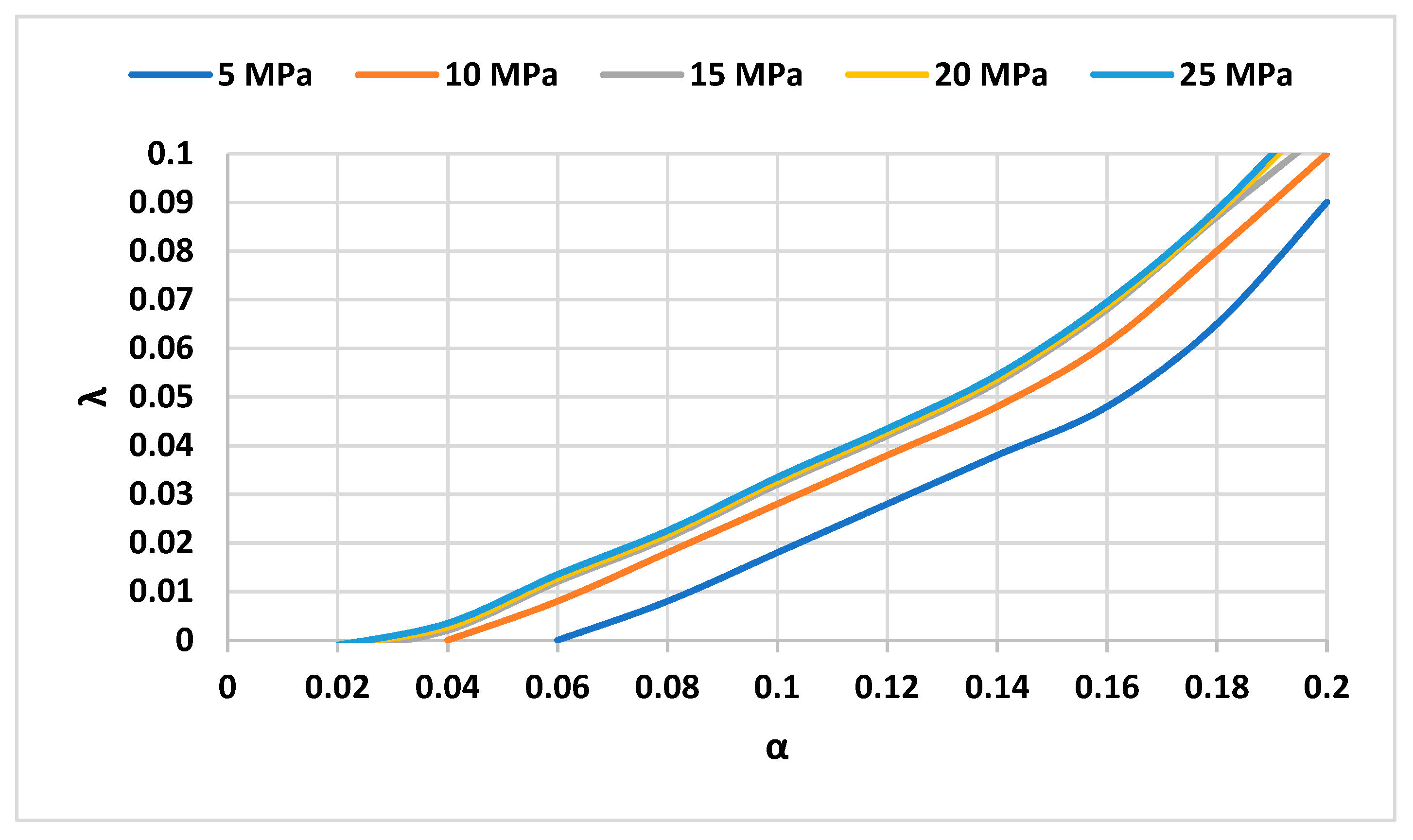
As is clear from Figure 7, the main influencing parameter is α, and the pressure is only a small amount in small values of α. It has a significant effect, but due to the relative nature of this value of 8 in small amounts, it can also be effective in the amount of energy saved and should be considered for the design of the system according to Figure 7 and Figure 8 for each design limit pressure. The reason for this can be found in Equation (4) because for each maximum pressure or system design, there is a certain minimum value; if the value of α is less than that, the residual pressure will be less than 10 MPa, that is, less than atmospheric pressure, which is not possible in practice. That is, for values smaller than the calculated minimum value in the emptying process, the expansion does not take place as much as the volume of the tank; thus, the value of 8 becomes negative. Using the designed air discharge mechanism, as the amount increases, we see a decrease in energy loss, and in this way, the amount of energy saved at different pressures increases with an increase of one hundred percent. The minimum possible amounts for pressures of 25 and 5 MPa are about 0.02 and 0.062, respectively. The difference between these two pressures in the maximum state (α) is equal to zero, about 0.017, and with an increase of α, this difference tends to zero. Figure 9 shows that the difference λ between the maximum and minimum operating pressures is considered relative to α.
To investigate the impacts of different parameters on γ , the effect of different parameters on the changes of 8 relatives to the operating pressure of the system has been analyzed for different values of α, Figure 10.
Figure 10 also confirms the results obtained for γ in Figure 11, Figure 12, Figure 13, Figure 14 and Figure 15 with increasing pressure for any given, the amount first increases and then remains constant at a certain value. As can be seen, except for low pressures, that for the minimum possible pressure in each, the amount of γ 8 is a function of α, and even the operating limit at lower pressures is also a function of α. In the same way, there is a minimum value for the maximum pressure for each “specified”, and if the operating pressure with the maximum system is lower than that value, λ becomes negative and the tank cannot be completely emptied, as it was said before, the reason for this is to reduce the residual pressure of the tank from the atmospheric pressure.
For example, the minimum and maximum possible pressure for values of α equal to 0.1 and 0.9 are 2.5 and 115 MPa, respectively, by increasing and decreasing the amount of water in the tank and increasing (the air draining the tank requires less energy, so the minimum possible pressure for the complete performance of the system is also reduced.

3.3. Determining the Dimensions of the Parameters

The values that achieve the effectiveness of this energy storage system include the capacity, energy, power capacity, and storage time of some parameters, as they affect these characteristics (Table 1). Concerning cost, the system also plays a fundamental role. Energy capacity is a function of storage pressure and tank volume; these are expressed as cost variables. For a given compressor and turbine, the system cost is directly comparable to the dimensions and wall thickness of the storage tank.
Correspondingly, the power capacity of the system is a function of the target pressure, but it is not a function of the tank volume. The “parameter” has been determined as a performance variable because its value directly affects the energy capacity, but in terms of cost, it is necessary to determine the size of the parameters. To determine a limit or a specific value, for this purpose, several methods have been performed to be able to choose the target volume of the tank depending on the need and the type of limitation of the pressure values. Operating pressure and tank volume mean the target pressure and the volume of the high-pressure tank because the volume of the low-pressure tank is determined according to the value of α and the volume of water in the system, and its pressure is the same as the residual pressure. The pressure values vary between 5 and 25 MPa. The main parameter for this system is the value, the selection of which is also decisive for the efficiency of the system. After choosing the considered a, depending on the amount of available energy (input) or output energy, the operating pressure of the system and the volume of the required tank can be selected. In addition, by assuming two system parameters, other parameters can be selected for system design.
Figure 11 shows the changes in work, work input, output, and energy stored in the tank about α. The volume of the tank is assumed to be 1000 m3 and the pressure value varies from 25 to 5 MPa according to the direction of the arrow from top to bottom with steps of 5 MPa. The maximum amounts of stored energy for pressures of 2025 and 5 MPa are 63,000, 50,000, and 12,500 MJ, respectively. In addition, the maximum point for output energy and input energy occurs for values equal to 0.431 and 535, respectively, even though the amount of stored energy increases continuously with the increase of the value, but the amount of the input and output energy and consequently the efficiency of the system decreases, the reason for this is the decrease in the amount of water in the system and the air discharge mechanism.
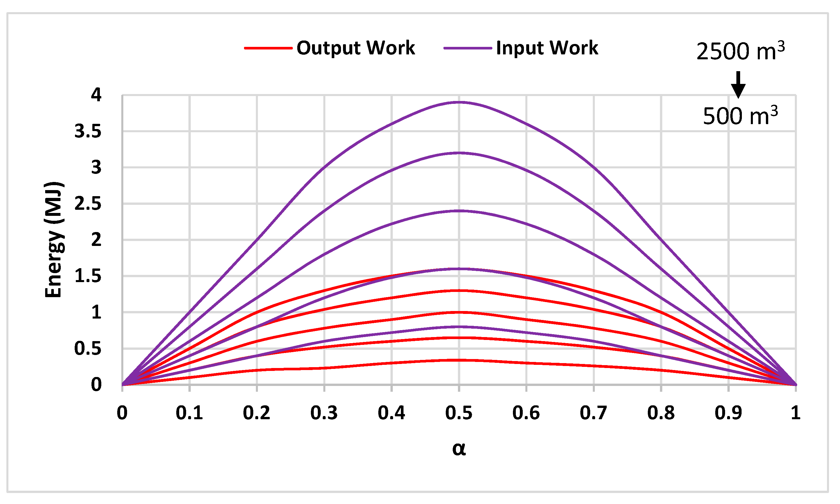
Figure 12 also shows the changes in the energy of the system concerning, but in this figure, the pressure is constant at 20 MPa and according to the direction of the arrow, the volume of the tank varies from 2500 to 500 m3 with steps of 500. A comparison of Figure 11 and Figure 12 indicates the same sensitivity of input and output energy of the system to the changes in pressure parameters and tank volume. Figure 13 shows the changes in the energy of the system relative to the pressure.
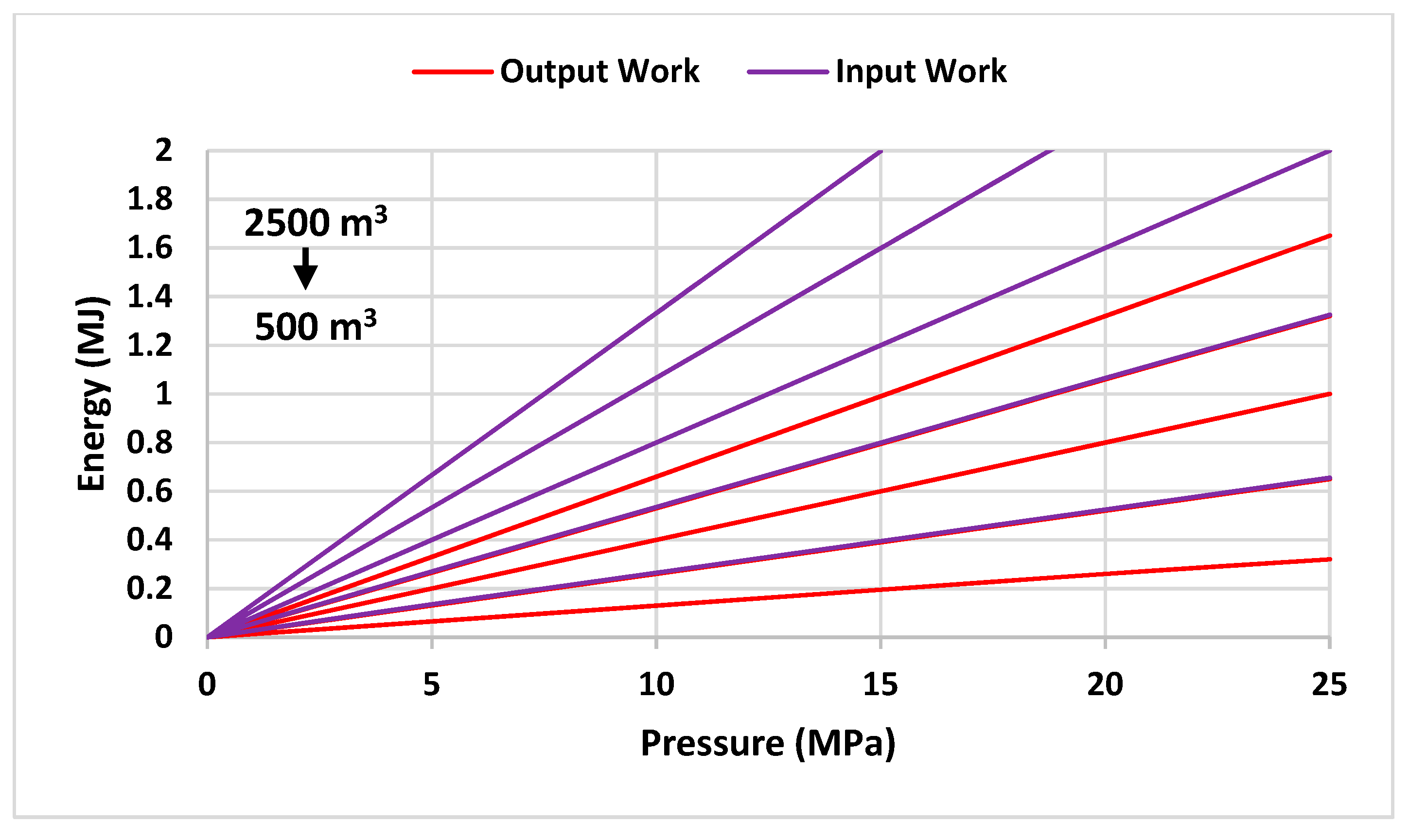
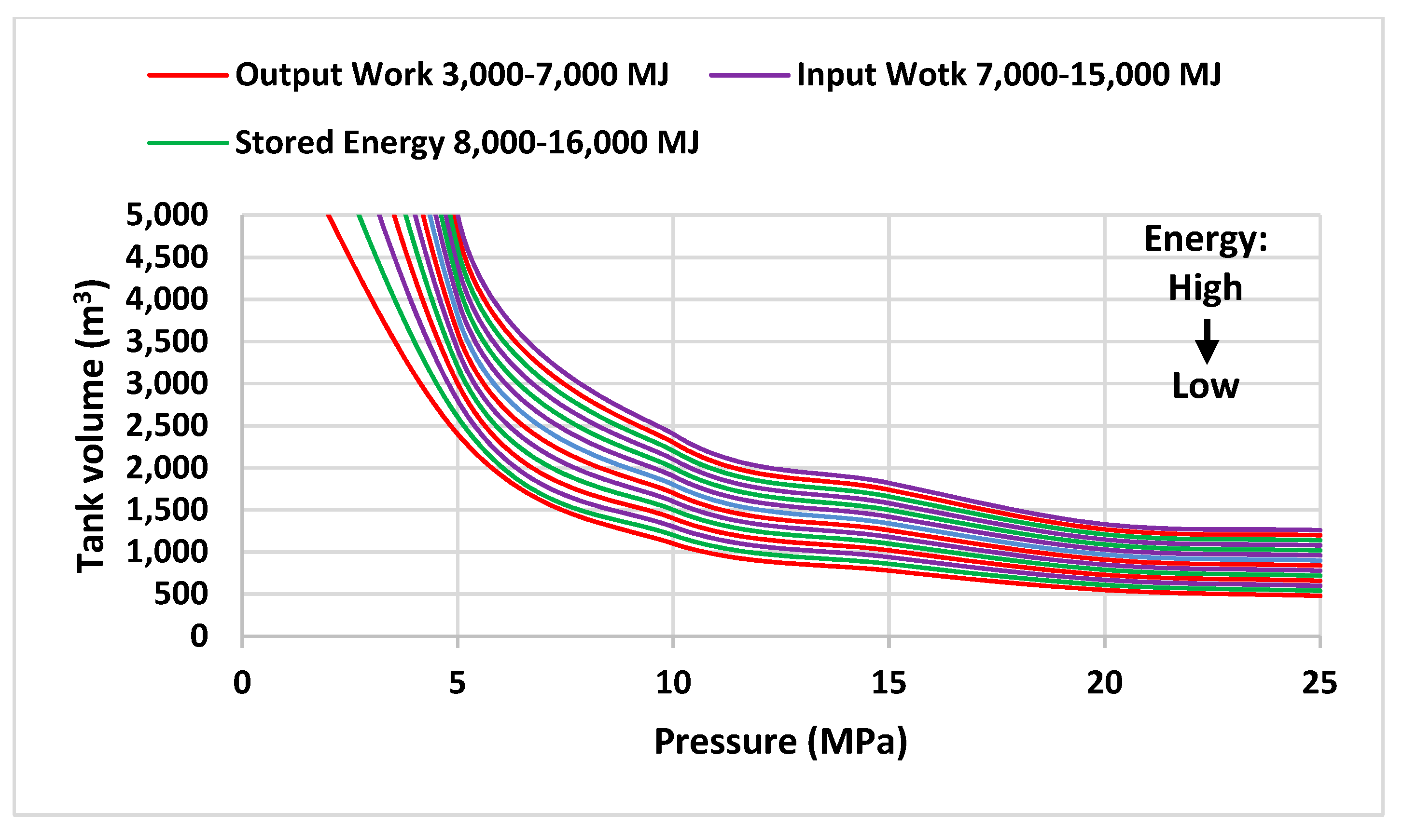
In this figure, the output work for the values of 9 times 4 and 0.5 is the opposite of the direction of the arrow; that is, the “curve” at 0.4 is higher than 0.5 because the peak or maximum point for the output work is equal to 0.431, and for values greater than this value, the slope will decrease. That is, at a certain pressure, the amount of output work will decrease by increasing the value of e to more than 0.431, and this critical value of α for input work is equal to 0.535. The maximum amount of stored energy for α is equal to 0.5, equal to 31,260 MJ, and the lowest amount is equal to 0.10, equal to 6251 MJ. In addition, the maximum stored energy against 0.4 is equal to 25,010 MJ. In addition, Figure 13 shows that the energy difference of the system in the critical range “for the same pressure is less than other values”. Figure 14 shows the changes in the energy of the system regarding the operating pressure, but in it, the amount of a is considered equal to 0.25, and the volume of the tank varies from 2500 to 500 m3 in steps of 500 according to the direction of the arrow. The maximum input energy in the pressure 25 MPa for the volume of 2500, 2000, and 500 m3 tanks is equal to 33,460, 26,770, and 6692 MJ, respectively. In addition, the comparison of Figure 13 and Figure 14 shows the greater sensitivity of system energy changes to α. Figure 15 shows the changes in the tank volume about the operating pressure of the system for input and output work and the same and constant stored energy of 5000 MJ. The value changes in the direction of the arrow from the top to the bottom. As shown in Figure 14, because the maximum output work in α is equal to 0.431, the curve equal to 0.4 for the output work is lower than curve 0.5. In addition, in the critical values, the difference in energy changes is less, and changes in pressure and tank volume do not affect this. It can be seen from Figure 15, which is particularly important for choosing design parameters such as operating pressure and tank volume and the amount of optimal energy output from the system because the energy output curves of the system are higher than the input and stored energy. Figure 16 shows the changes in the volume of the tank to the operating pressure of the system. In this figure, the value of α is constant and equal to 0.25, but the values of input work, output work, and stored energy are different and variable. These changes happen with fixed and specific steps, and according to the direction of the arrow, the amount of energy decreases from the top to the bottom.
The range of changes in input work, output work, and stored energy is selected according to Figure 11, Figure 12 and Figure 13. Figure 15 and Figure 16 show that at low values of pressure less than 5 MPa, the volume of the required reservoir increases with a steep slope, while at high values of pressure more than 10 MPa, the slope of the curve decreases. At very high values of pressure (more than 20 MPa), the changes in the volume of the reservoir are drastically reduced. Figure 17 shows the changes in the volume of the tank relative to a. In this figure, the amount of work input, output, and stored energy is the same, but this is the amount of pressure in the tank, which increases in the direction of the arrow from the top to the bottom. The pressure of the tank starts at 5 MPa and increases.
Additionally, it does not require special specifications for the implementation site for construction, and controlling the energy and heat of the system is easier than similar systems due to the use of water as an operating fluid. As a sign of these cases, this system is very scalable and can be designed in low to high capacities. The energy analysis of this research was carried out to identify the basic and influential parameters of the system and to determine the limitations and relationships between them so that, by using these results, depending on the goals and limitations, the path of system design and its feasibility will be paved. In short, the important results of the current research include the following: According to the results, it was found that it is possible to achieve an efficiency of about 92% in this system. The effective parameters of this system, such as the operating pressure or maximum pressure in the high-pressure tank, the volume of the tanks, and the amount of input and output of the system, are interdependent, but the most effective parameter in the design of this system is the ratio of air volume to the total volume in the high-pressure tank.
This numerical ratio can be between 0 and 1, which is the number. This means a tank without air, and the number 1 means a tank without water. The input and output work of the system and, as a result, the efficiency of the system depends on the ratio of air volume to the total volume of the high-pressure tank in such a way that it increases the ratio of air volume to the total volume of the pressure tank. The efficiency of the system decreases and reaches about 29% at the lowest value. The operating pressure range of the system was determined from 5 to 25 MPa, according to the results of this article and the background of the research. The upper range is considered according to the limitations of the existing technology. For the ratio of air volume to the total volume of the high-pressure tank, there are limits depending on the pressure. There is a system operation, and these limits are for its minimum amount, which is equal to 0.02 at 25 MPa pressure and 0.062 at 5 MPa pressure. The critical values of the air volume ratio to the total volume of the high-pressure tank for the input work and the output work of the system are 0535 and 0.431, respectively. Before these values, the capacity of the input work and the output work of the system increases, but after that, it decreases. The important strength of this system is in the stage of preparing the system to start energy storage. At this stage, by using the air discharge mechanism, the air pressure in the high-pressure and low-pressure tanks is equalized, and the water returns to the high-pressure tank without the need to consume additional energy. Using the air discharge mechanism, the waste of energy is prevented to a large extent. Without it, the residual air of the low-pressure tank, which has a pressure higher than the atmospheric pressure, must be completely discharged to the atmosphere, but by using this mechanism, only a part of it is discharged, and the amount of energy saved with the air discharge mechanism to the operating pressure. The volume of the high-pressure tank system and the ratio of the air volume depends on the total volume of the high-pressure tank and varies from 1 MJ to more than 50 MJ. Considering the amount of energy saved as a ratio to the input energy of the system, a clearer analysis. Thus, the ratio of energy saved to input energy is more a function of the ratio of air volume to the total volume of the high-pressure tank, and the operating pressure has less effect on it by increasing the ratio of air volume to the total volume of the high-pressure tank. The demand for the input energy of the system tends to be 1, which indicates that more energy saving and less input energy are needed in the next cycle of the system.
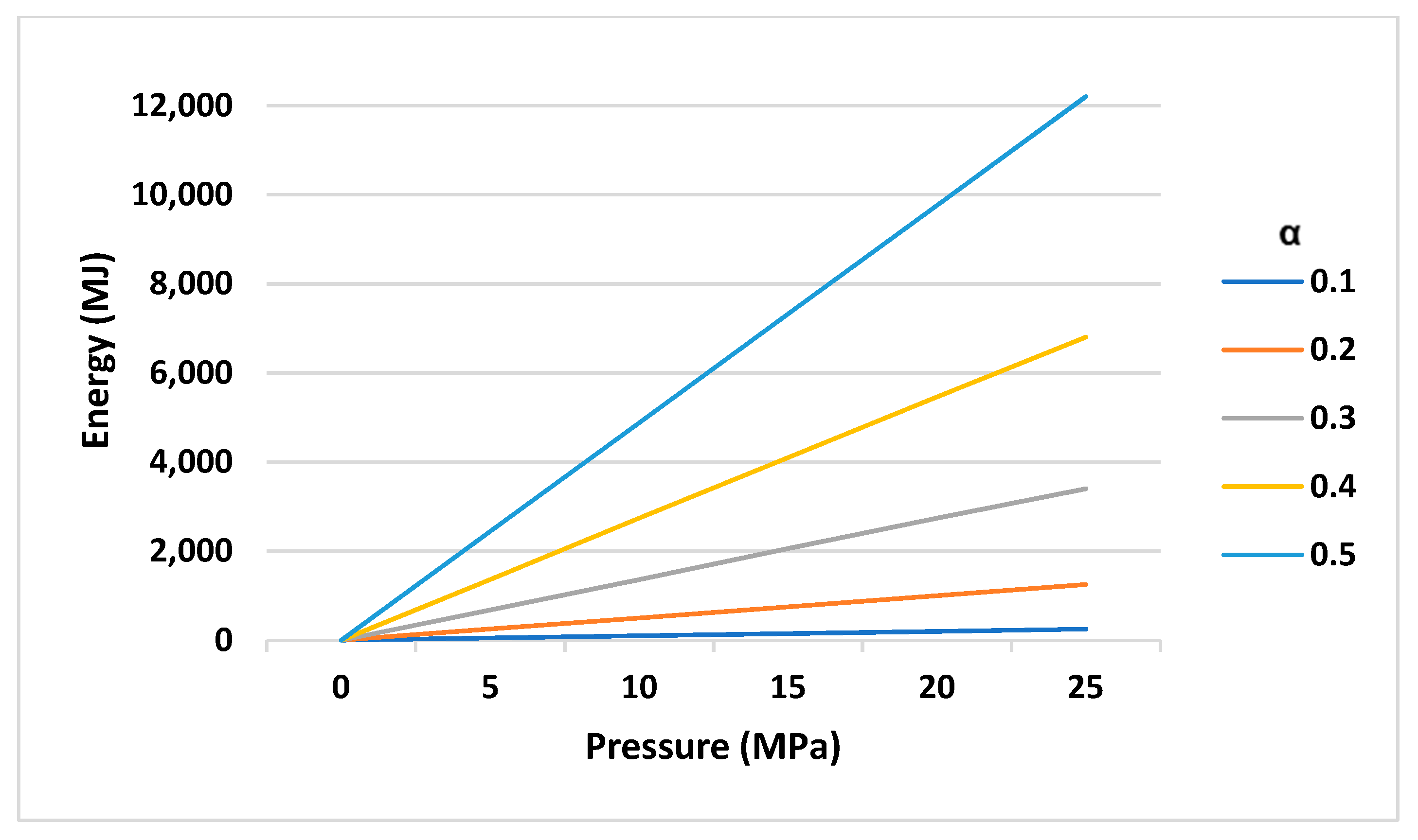
It increases by 25 MPa. At a certain value, with a decrease in pressure, the volume of the tank required to provide energy increases steadily. In addition, at high or low values, the need for the volume of the tank increases sharply. Figure 18 shows changes in the volume of the tank relative. In this figure, the values of input work, output work, and stored energy change, and the steps of changes are shown in the figure. The amount of energy decreases according to the direction of the arrow from top to bottom, and the tank pressure is 20 MPa. As is clear from Figure 11, Figure 17, and Figure 18, it increases with the increase in the amount of stored energy, but this issue does not increase the output work. The reason for this is the reduction in the initial amount of water and the air discharge mechanism mentioned earlier. In a certain operating pressure, the amount of energy changes at a constant rate with the change of the volume of the tank, but at low and high values, for the same amount of energy, the volume of the tank increases exponentially. In this section, the main parameters of the system and their impact on each other are evaluated. As previously stated, parameter e has the greatest effect on system performance, after which operating pressure is placed. The results presented in this section show that, for providing a certain amount of energy, high or low values of pressure of more than 20 and less than 5 MPa are not optimal. Additionally, to provide a minimum amount of energy [30], 5000 MJ depends on the operating pressure of the system to α. A tank with a volume between 500 and 2000 m3 is needed to be able to consider an optimal value for and bring the efficiency of the system to an acceptable level because, as it was said before, in high or low values, the amount of energy that can be extracted is greatly reduced. It is found that in the next section, according to these results, an energy analysis was performed to better evaluate the effectiveness of the air discharge mechanism and its effect on energy savings. The amount of energy saved by the air discharge mechanism was analyzed and investigated using the results of Section 3. The amount of energy saved by the air discharge mechanism during the system preparation stage. These results can be used in the selection. The parameters should be effective. Figure 19 shows the changes in energy saved compared to pressure. In this figure, the value varies from 0.1 to 0.5, and the volume of the tank is equal to 1000 m3, as it is known, the greatest energy saving occurs in large values of a. The reason for this is the reduction of the volume of the low-pressure tank, but this analysis is not correct without considering the results of Section 3. As mentioned earlier, with an increase in the amount of water, the volume of water decreases, so the amount of energy that can be extracted decreases. It varies up to 500 m3. As expected, with a constant amount of energy, a larger amount of energy is saved in the larger tank, which is directly proportional to the increase in pressure, as shown in Figure 19.
It is worth noting that this shows the effectiveness of the air discharge mechanism, but the value of α should also be considered for the design of the system because with the increase in pressure and volume of the tank, the amount of wasted energy will also increase.

4. Conclusions

The energy analysis of this research will identify the basic and effective parameters of the system and determine the limitations and relationships between them. Using these results, depending on the objectives and limitations, the path of the system design and its feasibility is paved. Morally, the important results of this study include the following:
  • The effective parameters of this system, including operational pressure or maximum pressure in the high-pressure tank, the volume of the tanks, and the rate of input and output work of the system, depend on each other; however, the most effective parameter in the design of this system is the ratio of air volume to total volume in the high-pressure tank. The input and output work of the system and, consequently, the efficiency of the system depend on the ratio of air volume to the total volume of the high-pressure tank. In this way, by increasing the ratio of air volume to the total volume of the high-pressure tank, the efficiency of the system decreases.
  • For the ratio of air volume to the total volume of the high-pressure tank, there are limitations depending on the operating pressure of the system, and these limits are for the minimum amount, which is equal to 0.02 at 25 MPa and 0.062 at 5 MPa. Critical values of air volume to the total volume of the high-pressure tank for input work and output work of the better system are 535.0 and 431.0, before these values, the input capacity and output work of the system is increasing but then decreasing;
  • Considering the amount of energy saved as a proportion of the input energy of the system, a clearer analysis is expressed. Thus, the ratio of energy savings to input energy is more a function of the ratio of air volume to the total volume of the high-pressure tank, and the operating pressure has a lower impact on it.

Author Contributions

Conceptualization, Z.L., A.A.A.A., M.J. and W.F.; methodology, Z.L., L.A.B.-A. and R.S.; software, Z.L., R.M.R.-P. and L.A.B.-A.; validation, R.M.R.-P., M.T.Q., Z.L., R.G. and M.A.G.; formal analysis, S.H.A.-K., F.N., R.S. and W.F.; investigation, Z.L. and R.A.; resources, S.H.A.-K., R.A., Z.L. and W.F.; data curation, Z.L., A.A.A.A., M.J., W.F., M.T.Q., M.A.G. and R.A.; writing—original draft preparation, Z.L. and L.A.B.-A.; writing—review and editing, A.A.A.A., S.H.A.-K., M.A.G., R.G., R.M.R.-P., R.S., L.A.B.-A., M.T.Q., Z.L., R.A. and W.F.; visualization, Z.L., F.N. and L.A.B.-A.; supervision, Z.L., L.A.B.-A. and W.F.; project administration, L.A.B.-A. and Z.L., funding R.G. and Z.L. All authors have read and agreed to the published version of the manuscript.

Funding

SGS Grant from VSB—Technical University of Ostrava under grand number SP2023/005.

Data Availability Statement

Data will be shared on request from first author.

Conflicts of Interest

The authors declare no conflict of interest.

Nomenclature

PResidual pressure(KPa) α Ratio of air volume to total volume
VVolume (m3) U Internal energy (J)
mMass (Kg)κPolytrophic constant
TTemperature (K) δ Ratio of the remaining energy in the tank to the stored energy
RGas constant (kJ/kg. K) μ Ratio of the remaining energy in the tank to the input energy
CSpecific heat capacity (kJ/kg. K)WPower (W)
γ Ratio of internal energy changes η Efficiency
vSpecial volume (m3/kg) λ Ratio of saved energy to input energy

References

  1. Denholm, P.; Mai, T. Timescales of energy storage needed for reducing renewable energy curtailment. Renew. Energy 2019, 130, 388–399. [Google Scholar] [CrossRef]
  2. Khazali, M.; Kaabi Nejadian, A. A study on the compressed air energy storage system. Mech. Eng. J. 2020, 29, 47–59. [Google Scholar]
  3. Akinyele, D.O.; Rayudu, R.K. Review of energy storage technologies for sustainable power networks. Sustain. Energy Technol. Assess. 2014, 8, 74–91. [Google Scholar] [CrossRef]
  4. Rehman, S.; Al-Hadhrami, L.M.; Alam, M.M. Pumped hydro energy storage system: A technological review. Renew. Sustain. Energy Rev. 2015, 44, 586–598. [Google Scholar] [CrossRef]
  5. Dursun, B.; Alboyaci, B. The contribution of wind-hydro pumped storage systems in meeting Turkey’s electric energy demand. Renew. Sustain. Energy Rev. 2010, 14, 1979–1988. [Google Scholar] [CrossRef]
  6. Wang, Z.; Carriveau, R.; Ting, D.S.; Xiong, W.; Wang, Z. A review of marine renewable energy storage. Int. J. Energy Res. 2019, 43, 6108–6150. [Google Scholar] [CrossRef]
  7. Khazali, M.; Abdalisousan, A. An Overview of Novel Energy Storage Systems with Air Compression Method. Iran. J. Energy 2020, 23, 47–82. [Google Scholar]
  8. Wolf, D.; Budt, M. LTA-CAES—A low-temperature approach to Adiabatic Compressed Air Energy Storage. Appl. Energy 2014, 125, 158–164. [Google Scholar] [CrossRef]
  9. Luo, X.; Wang, J.; Krupke, C.; Wang, Y.; Sheng, Y.; Li, J.; Yujie, X.; Dan, W.; Shihong, M.; Haisheng, C. Modelling study, efficiency analysis and optimisation of large-scale Adiabatic Compressed Air Energy Storage systems with low-temperature thermal storage. Appl. Energy 2016, 162, 589–600. [Google Scholar] [CrossRef]
  10. Li, Y.; Gao, W.; Ruan, Y.; Ushifusa, Y. The performance investigation of increasing share of photovoltaic generation in the public grid with pump hydro storage dispatch system, a case study in Japan. Energy 2018, 164, 811–821. [Google Scholar] [CrossRef]
  11. Zhang, Y.; Xu, Y.; Guo, H.; Zhang, X.; Guo, C.; Chen, H. A hybrid energy storage system with optimized operating strategy for mitigating wind power fluctuations. Renew. Energy 2018, 125, 121–132. [Google Scholar] [CrossRef]
  12. Guo, H.; Xu, Y.; Chen, H.; Zhou, X. Thermodynamic characteristics of a novel supercritical compressed air energy storage system. Energy Convers. Manag. 2016, 115, 167–177. [Google Scholar] [CrossRef]
  13. Khalil, K.M.; Ahmad, A.; Mahmoud, S.; Al-Dadah, R.K. Liquid air/nitrogen energy storage and power generation system for micro-grid applications. J. Clean. Prod. 2017, 164, 606–617. [Google Scholar] [CrossRef]
  14. Guizzi, G.L.; Manno, M.; Tolomei, L.M.; Vitali, R.M. Thermodynamic analysis of a liquid air energy storage system. Energy 2015, 93, 1639–1647. [Google Scholar] [CrossRef]
  15. Xie, C.; Hong, Y.; Ding, Y.; Li, Y.; Radcliffe, J. An economic feasibility assessment of decoupled energy storage in the UK: With liquid air energy storage as a case study. Appl. Energy 2018, 225, 244–257. [Google Scholar] [CrossRef]
  16. Farres-Antunez, P.; Xue, H.; White, A.J. Thermodynamic analysis and optimization of a combined liquid air and pumped thermal energy storage cycle. J. Energy Storage 2018, 18, 90–102. [Google Scholar] [CrossRef]
  17. Nabat, M.H.; Zeynalian, M.; Razmi, A.R.; Arabkoohsar, A.; Soltani, M. Energy, exergy, and economic analyses of an innovative energy storage system, liquid air energy storage (LAES) combined with high-temperature thermal energy storage (HTES). Energy Convers. Manag. 2020, 226, 113486. [Google Scholar] [CrossRef]
  18. Kantharaj, B.; Garvey, S.; Pimm, A. Thermodynamic analysis of a hybrid energy storage system based on compressed air and liquid air. Sustain. Energy Technol. Assess. 2015, 11, 159–164. [Google Scholar] [CrossRef]
  19. An, B.; Chen, J.; Deng, Z.; Zhang, T.; Wang, J.; Yang, L.; Chang, X. Design and testing of a high performance liquid phase cold storage system for liquid air energy storage. Energy Convers. Manag. 2020, 226, 113520. [Google Scholar] [CrossRef]
  20. Kim, Y.M.; Shin, D.G.; Favrat, D. Operating characteristics of constant-pressure compressed air energy storage (CAES) system combined with pumped hydro storage based on energy and exergy analysis. Energy 2011, 36, 6220–6233. [Google Scholar] [CrossRef]
  21. Wang, Z.; Ting, D.S.K.; Carriveau, R.; Xiong, W.; Wang, Z. Design and thermodynamic analysis of a multi-level underwater compressed air energy storage system. J. Energy Storage 2016, 5, 203–211. [Google Scholar] [CrossRef]
  22. Klar, R.; Steidl, B.; Aufleger, M. A floating energy storage system based on fabric. Ocean. Eng. 2018, 165, 328–335. [Google Scholar] [CrossRef]
  23. Yao, E.; Wang, H.; Xi, G. A Novel Pumped Hydro Combined with Compressed Air Energy [Internet]. In Storing Energy; Letcher, T.M., Ed.; Elsevier: Amsterdam, The Netherlands, 2016; pp. 155–166. [Google Scholar]
  24. Heidenreich, D.C. Compressed Air Pumped Hydro Energy Storage and Distribution System F03B13/00. U.S. Patent No. 7,281,371, 16 October 2007. [Google Scholar]
  25. Laugier, A.; Garai, J. Derivation of the ideal gas law. J. Chem. Educ. 2007, 84, 1832–1833. [Google Scholar] [CrossRef]
  26. Sposito, G.; Chu, S.Y. Internal Energy Balance and the Richards Equation. Soil Sci. Soc. Am. J. 1982, 46, 889–893. [Google Scholar] [CrossRef]
  27. Erlichson, H. Internal energy in the first law of thermodynamics. Am. J. Phys. 1984, 52, 623–625. [Google Scholar] [CrossRef]
  28. Cengel, Y.A.; Boles, M.A. Thermodynamics, an Engineering Approach; McGraw-Hill Education: New York, NY, USA, 2015; pp. 359–366. [Google Scholar]
  29. Villela, D.; Kasinathan, V.V.; De Valle, S.; Alvarez, M.; Frantziskonis, G.; Deymier, P.; Krishna, M. Compressed-air energy storage systems for stand-alone off-grid photovoltaic modules [Internet]. In Proceedings of the IEEE Photovoltaic Specialists Conference, Honolulu, Hawaii, 20–25 June 2010; pp. 962–967. [Google Scholar]
  30. Wang, H.; Wang, L.; Wang, X.; Yao, E. A Novel Pumped Hydro Combined with Compressed Air Energy Storage System. Energies 2013, 6, 1554–1567. [Google Scholar] [CrossRef]
  31. Bi, J.; Jiang, T.; Chen, W.; Ma, X. Research on Storage Capacity of Compressed Air Pumped Hydro Energy Storage Equipment. Energy Power Eng. 2013, 5, 26–30. [Google Scholar] [CrossRef]
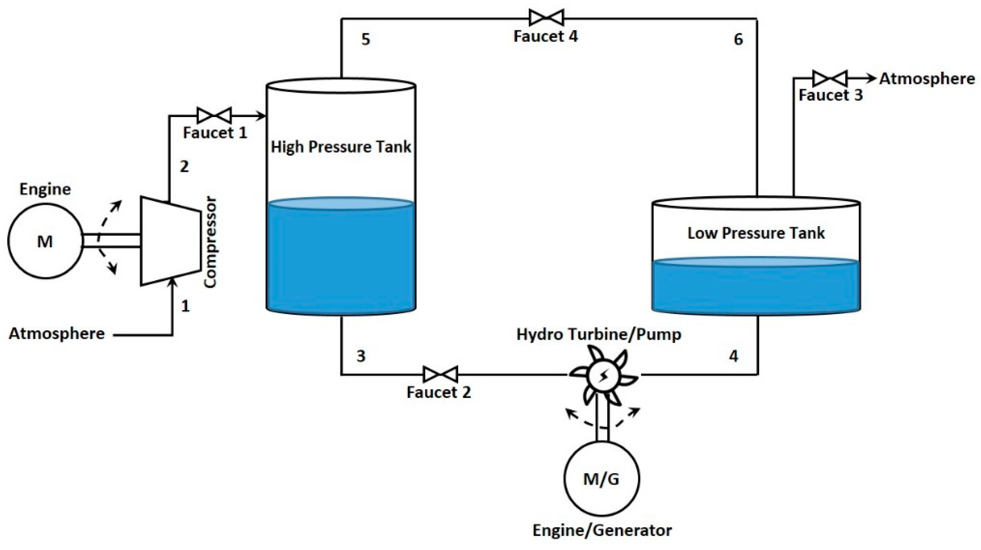
Figure 1. A schematic view of the combined energy storage system of compressed air and the storage pump.
Energies 16 02337 g001
Figure 2. State of the high-pressure tank during the process of charging and discharging.
Energies 16 02337 g002
Figure 3. Different states of the high-pressure tank during the process of charging and discharging, assuming that it is closed.
Energies 16 02337 g003
Figure 4. Changes in the conducted work compared to the air volume inside the tank [29].
Energies 16 02337 g004
Figure 5. Changes in output energy density for a residual pressure of: (A) 2.5 MPa; (B) 3.2 MPa and; (C) 25MPa compared to ϵ under pressure conditions [30].
Energies 16 02337 g005aEnergies 16 02337 g005b
Figure 6. Pressure changes for a residual pressure of: (A) 2.5 MPa; (B) 3.2 MPa and; (C) 25MPa compared to compared to ϵ for the three studies in three different states [30].
Energies 16 02337 g006aEnergies 16 02337 g006b
Figure 7. Changes of λ about α for different operating pressures.
Energies 16 02337 g007
Figure 8. Changes of λ at different operating pressures compared to low values of α.
Energies 16 02337 g008
Figure 9. The difference λ between the maximum and minimum operating pressures is considered relative to α.
Energies 16 02337 g009
Figure 10. Changes of λ about pressure for different values of α.
Energies 16 02337 g010
Figure 11. Changes in work input, output, and energy stored in the tank about α for different pressures and specific tank volume (1000 m3).
Energies 16 02337 g011
Figure 12. Changes in input and output work relative to α for the constant pressure of 20 MPa and different tank volumes (from 2500 to 500 with a step of 500 m3).
Energies 16 02337 g012
Figure 13. Changes in input work, output work, and stored energy relative to pressure for different values of α with a tank volume of 1000 m3.
Energies 16 02337 g013
Figure 14. Changes in input and output work relative to pressure for α value equal to 0.25 for different tank volumes (from 2500 to 500 with steps of 500 m3).
Energies 16 02337 g014
Figure 15. Reservoir volume changes about pressure for a specific input work, output work, and stored energy (5000 MJ) for different values of α (0.1 to 0.5).
Energies 16 02337 g015
Figure 16. Changes in tank volume with pressure for α value equal to 0.25 for input work, output work, and stored energy, and different stored energy.
Energies 16 02337 g016
Figure 17. Reservoir volume changes concerning α for a specific input work, output work, and stored energy (5000 MJ) for different pressures (5 to 25 MPa with steps of 5 MPa).
Energies 16 02337 g017
Figure 18. Reservoir volume changes about α for different values of input work, output work, and stored energy for a specific pressure (20 MPa).
Energies 16 02337 g018
Figure 19. Changes in saved energy compared to pressure for different values of α and tank volume of 1000 m3).
Energies 16 02337 g019
Table 1. Various parameters affect power, energy, and cost capacities.
ParametersEffective FactorsVariable Type
CostEnergyPower
Target pressureCost and Performance
Tank volume-Cost
α --Performance
Disclaimer/Publisher’s Note: The statements, opinions and data contained in all publications are solely those of the individual author(s) and contributor(s) and not of MDPI and/or the editor(s). MDPI and/or the editor(s) disclaim responsibility for any injury to people or property resulting from any ideas, methods, instructions or products referred to in the content.