Abstract
A single–phase flow model was used to analyze the uniformity of the flow field in the desulfurization tower under different baffle combinations, and a multiphase flow model was used to explain the gas and solid two–phase flow characteristics and chemical reaction characteristics in the tower. The stability of the flow behavior of gas and solids in one furnace and two towers was discussed. The results show that the installation of shielding plates at appropriate positions in the tower for sulfur removal is beneficial to enhance the uniform distribution of flow in space, reduce the pulsation interference of bed pressure in the tower, keep the state of gas and solid flow unchanged, and maintain the efficiency of desulfurization at a high level. Reducing the instability of gas–solid two–phase flow is the basis of ensuring the stable switching between single and double towers.
1. Introduction
The 600 MW supercritical circulating fluidized bed boiler (SCCFB) generator unit located in Baima Power Plant in Sichuan Province is of outstanding innovation significance in the field of the circulating fluidized bed power generation technology in China. The emission limits have been reduced in China. The unit is currently carrying out ultra–low emission transformation of flue–gas pollutants [1]: the emission concentrations of NOx, SO2 and smoke are lower than 50 mg/Nm3, 35 mg/Nm3 and 5 mg/Nm3, respectively, after the transformation. Desulfurization by limestone addition to the fluidized bed boiler (CFB) is not sufficient to satisfy the regulations. However, the desulfurization cost is cheaper. Therefore, the adoption of semi–dry flue–gas desulfurization [2,3,4,5] on the basis of desulfurization in the furnace was considered. The semi–dry method has advantages of low investment and low operation cost. Semi–dry flue–gas desulfurization includes rotary spray and circulating bed desulfurization. The latter has high desulfurization efficiency and a small floor area, which is suitable for SCCFB ultra–low emission transformation reconstruction projects. The circulating fluidized bed semi–dry desulfurization technology has been studied by many scholars to optimize the technology since it appeared in the 1980s. Water is the premise of the acid–base neutralization reaction. Selecting the appropriate amount [6,7] and spraying evenly [8,9,10] is the key to improving the desulfurization efficiency. The optimization of adsorbent [11,12,13] is an important development direction of semi–dry desulfurization technology. At the same time, the uncertainty caused by the load change in the unit makes the monitoring and calculation [14,15] of the parameters in the system become the key link for the normal operation of the desulfurization tower.
For circulating fluidized bed flue–gas desulfurization, the bed material (desulfurizer carrier, similar to a small plastic ball) needs to be fluidized. The fluidizing medium is flue gas. When the boiler load is low, it is difficult to completely fluidize the flue–gas volume in the desulfurization section in the desulfurization tower. As the load of the unit varies greatly (30–100%, boiler maximum continuous rating, BMCR), a special arrangement is required: a two–reactor solution called “two–tower semi–dry desulfurization” (“one furnace with two towers”, i.e., one furnace corresponds to two desulfurization towers) to guarantee the qualified operation of the desulfurization system. Two desulfurization towers with 50% load to operate in parallel to deal with the desulfurization problem when the load changes over a wide range were designed. When the unit load operating is below 50% BMCR, the single tower and single induced fan are used for operation, and when the unit load is above 50% BMCR, the double towers and double induced fans are used to achieve the economical operation of the environmental protection system under the full load of the unit [16]. According to this scheme, the project requires the unit to achieve stable and reliable switching between single and double towers when the load changes, and ensure that the flue gas reaches ultra–low emission standards during the switching process. Therefore, it is extremely important to match the operation parameters of the boiler and parallel double desulfurization tower. As the “two–tower semi–dry desulfurization” is the first system in the world, there is no successful long–term implementation and reliable operation case for reference [17]. The relevant issues are worth studying.
The Ca(OH)2 material concentration in the desulfurization tower is high, and the materials will collide with each other and form agglomeration during the movement process, which has a great impact on the desulfurization effect [18,19,20,21]. Generally, only optimizing the single–phase flue–gas flow field in the empty tower cannot effectively meet the design requirements under the current ultra–clean flue–gas emission requirements. A two–phase flow calculation scheme based on droplet evaporation and desulfurization chemical reaction must be adopted. In this paper, the numerical simulation theory of the two–phase flow of solid and gas flows based on the computational fluid dynamics–discrete element model (CFD–DEM) method was used to simulate the gas–solid two–phase flow, desulfurization chemical reaction and the stability of the gas–solid two–phase flow in the process of switching between single and double towers in the semi–dry desulfurization system [6,22,23].
2. Numerical Simulation of Gas–Solid Two–Phase Flow
2.1. Mathematical Model Building
In order to enhance the uniformity and symmetry of fluid flow in the desulfurization tower, a reasonable baffle structure group must be set up. The single-phase fluid calculation model used includes the following parts [24,25]:
(1) Continuity equation:
(2) Momentum equation:
In this paper, the discrete element model (DEM) was used to describe the motion behavior of particles. The CFD–DEM calculation method includes the fluid flow conservation equation and the particle motion tracking equation [26,27], which are summarized as follows:
(1) Gas continuity equation
(2) Gas momentum equation
(3) Particle translation and rotation tracking equations
In the semi–dry flue–gas desulfurization process, the absorption reaction of SO2 gas mainly includes the following continuous processes: the diffusion of SO2 in the gas phase, the absorption of SO2 by the liquid surface film, the ionization of SO2 in the liquid surface film, the transfer of from the liquid phase to the reaction interface, the dissolution of the absorbent on the surface of the absorbent particles, the transfer of the dissolved absorbent to the reaction interface, the diffusion of the dissolved absorbent and the through the CaSO3/CaSO4 deposit, and the ionic reaction between dissolved absorbent and .
Studies show [28] that the actual chemical reaction rate is much higher than the dissolution and diffusion rate of desulfurizer particles and sulfur ions in the droplets of desulfurization liquid. Therefore, the reaction of dissolved in the droplets with the desulfurizer Ca(OH)2 is considered to be instantaneous, and only the dissolution and diffusion of SO2 and Ca(OH)2 are concerned. In order to comprehensively investigate the physical and chemical reactions in the desulfurization tower, the two–membrane theory [28,29], as shown in Figure 1, was used to describe the sulfur removal reaction [30]. So, making the following assumptions:
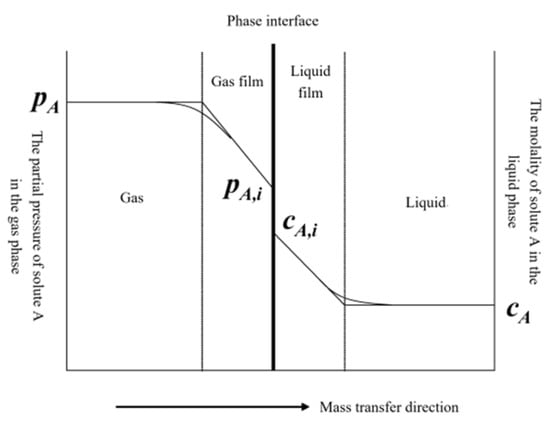
Figure 1.
Schematic diagram of two–film theory.
- (1)
- Both liquid and desulfurizer particles are spherical in shape;
- (2)
- Because the liquid phase ionic reaction rate between sulfite ions dissolved in water and calcium ions is fast, the chemical reaction rate during sulfur removal is not considered to be an influential parameter, compared with the mass transfer process;
- (3)
- The reaction is only carried out in the liquid surface film; the reactants cannot coexist in the liquid surface film, and the reaction only occurs on one side of the liquid surface film;
- (4)
- It is considered that the internal temperature of the slurry droplets is uniform;
- (5)
- The liquid evaporation follows Raoult’s law and does not consider phase transition;
- (6)
- The influence of other components in the flue gas, such as CO2, on the desulfurization process is not considered.
The mass transfer flux of SO2 in the gas film, , is shown in the following formula [31,32,33]:
where is the mass transfer coefficient of SO2 in the gas film, the unit is m s−1; and are the partial pressure of SO2 at the gas–phase main body and the gas film surface, the unit is kPa.
The mass transfer flux of SO2 in the liquid surface film, , is given by the following formula [31,32,33]:
where represents the mass transfer coefficient of SO2 in the liquid surface film, the unit is m s−1; represents the concentration of SO2 at the surface of the liquid surface film, the unit is kmol m−3. Where E represents the enhancement factor, which is defined as:
and represent the diffusion coefficients of SO2 and Ca(OH)2 in the liquid surface film, respectively, the unit is m2 s−1; represents the concentration of Ca(OH)2 at the surface of the liquid surface film; the unit is kmol m−3.
The partial pressure of SO2 at the main body of the gas phase and the concentration at the surface of the liquid surface film can be related by the Henry coefficient :
Assuming that the Ca(OH)2 concentration in the liquid surface film is uniform and constant, the dissolved flux of Ca(OH)2, , and its saturation concentration have the following relationship:
where represents the mass transfer coefficient of Ca(OH)2, the unit is m s−1; and represents the saturated concentration and the concentration of Ca(OH)2 in the liquid surface film, respectively; the unit is kmol m−3.
The relationship between the mass transfer flux of SO2, , and the dissolution flux of Ca(OH)2 is as follows:
where and represent the surface area of lime particles and the surface area of slurry droplets, respectively.
The SO2 reaction rate can be obtained by combining the above formulas:
where
Sh, dp and Pliq represent the mass transfer Sherwood number, the droplet diameter and the partial pressure of water vapor on the surface of droplets, respectively.
2.2. Desulfurization Tower Parameters and Numerical Simulation Conditions
The flue gas from the flue–gas passage at the tail of the boiler is dedusted by the pre–electrostatic precipitator and then enters the desulfurization tower. The desulfurization tower is an empty tower structure with seven Venturi nozzles. When the Venturi nozzle part of the desulfurization tower has sulfur flue gas through, the desulfurization agent and the desulfurization circulating ash are fluidized and sent to the desulfurization tower. At the same time, humidification with water spray and washing in the absorption area to remove sulfur dioxide in the flue gas is applied. Air flow regulating baffles are arranged at the bottom of the inner space of the tower to optimize the uniformity of the flow field. The flue–gas flow rate in the desulfurization tower is 5 m/s, and the reaction residence time is more than 6 s, which fully guarantees the desulfurization reaction and the uniform mixing of gas, liquid and solid.
In order to ensure the qualified removal of sulfur, it is necessary to maintain a large flow rate at the Venturi section, so that the particle concentration in the desulfurization tower is maintained at a high level, and the fluidization velocity is proportional to the total flow rate of flue gas containing sulfur. The flow rate of flue gas varies with the boiler load. In order to adapt to the change in load and ensure the stability of the fluidized bed in the desulfurization tower, the net flue–gas recirculation load regulation system is set up. When the boiler load is below 70%, the system is adjusted by the gas recirculation. The net flue gas is let out from the flue gas behind the induced draft fan and enters the inlet of the desulfurization tower after passing through the regulating damper valve. In order to ensure the economy of the unit under low load, single tower operation is adopted when the load is below 60% BMCR, and double tower operation is switched when the load is higher than 60% BMCR. In order to realize the switch between single and double towers, a connecting flue pipe and a baffle door are set between the two towers’ inlet flue pipes and the two towers’ recirculation flue pipes.
The bed and grid structures for the computational domain are illustrated in Figure 2. The geometry parameters of the desulfurization tower are listed in Table 1.
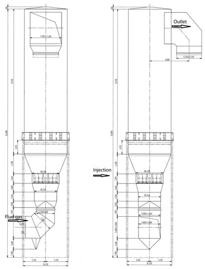
Figure 2.
Schematics of the desulfurization tower.

Table 1.
The geometry parameters of the desulfurization tower.
The data parameters required for the simulation in this paper are listed in Table 2, where the flue–flow rate at the entrance of desulfurization tower in the table is the flue–gas–flow rate at 100% MBCR. The boundary condition at the wall is defined as no–slip for the gas phase and free–slip for the solid phase.
Table 2.
Simulation parameters.
The uniform grids were generated by the Barracuda software with the spray nozzle and baffle plates refined locally. The grid independence verification results showed that the reasonable total mesh number was 7,900,000.
3. Results and Discussions
3.1. Single–Phase Flow Simulation
The baffle plate is an important device to ensure stable flow in the flue–gas channel and reduce fluid resistance. Therefore, the single–phase flow model was used first to determine the form of the baffle in the flue pipes.
Figure 3 shows the baffle arrangement in the flue pipes connected to the tower entrance and the flow velocity distribution in the desulfurization tower. The arrangement of a baffle in a flue–gas passage connected with the entrance of the tower is shown in Figure 3a, and it can be seen that the setting of the baffle plates comprehensively considered the diversion effect and the difficulty of actual installation. The deflector usually needs to be reasonably set in the flue–gas steering (right angle bend, arc bend, etc.), flue–gas confluence (flue–gas recirculation inlet, flue–gas confluence after electrostatic precipitator, etc.). Through simulation, it was found that the system resistance was 1560 Pa when the baffle plates were not set, and the system resistance was reduced to 1100 Pa after the baffle plates were set. The spatial distribution of fluid flow in the tower is shown in Figure 3b. Obviously, the flow distribution above the Venturi tube is symmetrical, which enhances the stability of gas–solid two–phase flow in the tower.
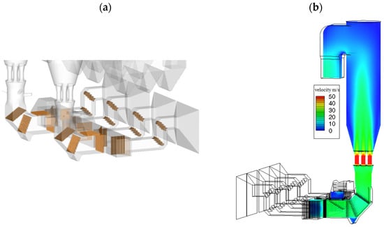
Figure 3.
Layout of baffle plates and flow field distribution in desulfurization tower. (a) Baffle plates layout at flue; (b) flow field distribution at xz cross section.
3.2. Characteristics of Two–Phase Flow of Solid and Gas Flows in Desulfurization Tower
Under the condition that the unit load is 100% BMCR and the two towers handle 50% of the flue–gas volume, respectively, Figure 4 shows the distribution of the desulfurizer in the tower at t = 5 s, 10 s, and 15 s for the two towers.
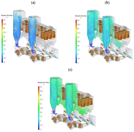
Figure 4.
Particle distribution in the tower at different times. (a) t = 5 s (b) t = 10 s (c) t = 15 s.
It can be seen from Figure 4 that: (1) The flow pattern in the desulfurization towers was fast fluidization flow. The materials in a single tower are evenly distributed within the tower, which is beneficial for improving the stability of the gas–solid two–phase flow and desulfurization tower operation (with low fluctuation of bed pressure), achieving desulfurization efficiency and improving operation economy (on the premise of less desulfurizer consumption); (2) When the two desulfurization towers operate independently, the distribution of desulfurizer inside them is basically the same. This is mainly because the two desulfurization systems are arranged symmetrically and the baffle plates are set the same, so the gas–solid two–phase flow behavior in the towers is basically the same; (3) There will be a certain amount of ash accumulation at the bottom of the outlet horn of the electrostatic precipitator, and the ash outlet should be set appropriately.
Based on the desulfurization and other chemical reaction models, the spatial distribution of SO2 concentration in two towers at t = 5 s, 10 s, and 15 s under the unit’s full load was simulated, as shown in Figure 5. It can be seen that after the SO2 in the flue gas came into contact with the desulfurizer, it achieved rapid desulfurization under the action of water spray, and the concentration of SO2 located at the outlet of the bag filter reached the design value ≤ 5 mg Nm−3.
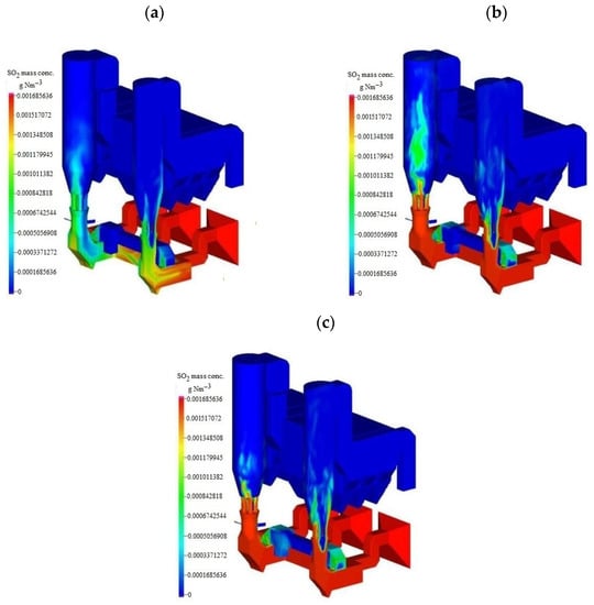
Figure 5.
Distribution of SO2 mass concentration in the tower at different times. (a) t = 5 s (b) t = 10 s (c) t =15 s.
3.3. Gas–Solid Flow Characteristics of Single Tower and Double Tower Switching
In order to ensure the stable and economical operation of the unit, the single tower can meet the maximum load of the unit at 60% BMCR operation. When the total boiler load is less than 60% BMCR for a long time, it adopts single–tower operation, and when the boiler load is greater than 60% BMCR, it adopts double–tower operation. The single–tower and double–tower switching control scheme comprises the setting of a connecting flue pipe and a baffle door between the two towers’ inlet flue pipes and the two towers’ recirculation flue pipes. Through the opening and closing of each baffle door, stable switching between the single and double towers can be achieved. In order to ensure the stability of the switching process, the unit load is required to remain stable at 50%~55% BMCR until after the end of the single and double tower switching process. It ensures that small fluctuations in the load will not cause large–scale fluctuations in flue–gas flow. It also ensures gas–solid two–phase flow in two desulfurization tower stability. The unit can increase/decrease load operation after the switching process is completed.
Based on the control scheme of switching from single tower to double towers, the material flow behavior in the tower was simulated. A single desulfurization tower under different unit load (flue–gas volume) conditions can ensure good and stable flow characteristics (from the actual operation, bed pressure drop fluctuation < ±100 Pa). It effectively avoids the bed collapse caused by unstable gas–solid flow in the desulfurization tower (in practical applications, a single tower can run stably at a unit load of 15% BMCR). Therefore, the stable operation of the single tower was the key premise to ensure the stable switch between single tower and double towers.
Figure 6 shows the material concentration distribution in the tower at the t = 5 s, 10 s, and 15 s time. Figure 6 shows the change in inlet flow and recirculation flue cross–section flow over time for two towers: (1) Tower A operates at 60% BMCR of unit load; (2) The flue gas entering tower B is divided into two parts, one part is the net flue gas after desulfurization of tower A, and the other part is the flue gas after the recirculation of tower B itself.
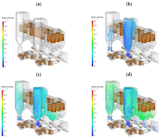
Figure 6.
Particle distribution in towers at different times when single tower operation is switched to double tower operation; (a) t = 0 s (b) t = 5 s (c) t = 10 s (d) t = 15 s.
As shown in Figure 6, the flow rate at the inlet section of tower A peaked after 0.9 s and was finally maintained at 497 ± 20 kg s−1. The recirculation flue–gas flow into tower A had large fluctuations in the initial stage of 0–4.3 s, and then stabilized at 310 ± 5 kg s−1. The inlet cross–section gas flow of tower B reached a stable state after 1.0 s and remained at 159 kg s−1; the recirculation flue–gas flow reached a stable state after 4.0 s and remained at 159 kg s−1; both fluctuated slightly. The flow fluctuation at the inlet of tower A was more obvious than that at the inlet of tower B and in the recirculation flue pipe. Combined with Figure 7, it was found that the material concentration in tower A was larger, and the fluctuation of bed pressure drop was larger, which caused a certain fluctuation in the inlet flow of tower A. There was less material in tower B, the bed pressure drop fluctuation was small. The inlet net flue–gas flow was stable, the recirculation flue contained almost no dust. So, it had the weakest impact on flow fluctuations.
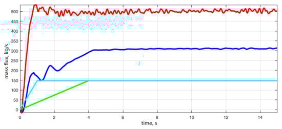
Figure 7.
Flue–gas flow rate of tower A/B inlet section and recirculation flue inlet section (red: entrance to tower A; blue: entrance to tower B; turquoise: recirculation flue section of tower A; green: recirculation flue section of tower B).
Meanwhile, it could be found from Figure 7 that: (1) In the process of switching from single tower to double towers, the material concentration in tower A was evenly distributed, which could promote the stability of the desulfurization operation and guaranteed the desulfurization efficiency; (2) The flue gas in tower B was net flue gas. A good material circulation in the tower with low fluctuation of bed pressure was established to achieve some desulfurization, which created conditions for the introduction of raw flue gas containing SO2 to achieve stable desulfurization in the next stage.
3.4. Comparison of Simulation Results with Experimental Results
The results of the single–tower and double–tower switching test of the desulfurization towers are shown in Table 3. The testing of flue–gas flow, bed pressure and SO2 concentration at inlet and outlet was carried out during the switching process of single to double towers and the operation of double towers under 60 and 100% BMCR load.
Table 3.
Test results of switching between single and double desulfurization towers.
As shown in Table 3:
- (1)
- During the operation of the double tower and the single tower, the flue–gas flow rate of tower A changed greatly, increasing from 1251 kNm3 h−1 to 1634 kNm3 h−1, due to the stopping of operation of tower B and the decrease in the recirculated flue gas volume at the same time. During the switching process, the change in the bed pressure of tower A was small, and the flue–gas flow and bed pressure of tower B before and after the switching test of the single and double towers were also low. This showed that the concentration distribution of chemical substances in the desulfurization tower was uniform during the switching process, which was the same as the simulation result;
- (2)
- When the two towers operated under loads of 60 and 100% BMCR, the flue–gas flow and the bed pressure of the two towers were not much different, and the deviation was less than 5%. This means that the distribution of the desulfurization agent inside was basically the same, and as the two desulfurization systems are arranged symmetrically, the gas–solid two–phase flow behavior in the tower was basically the same, which was the same as the simulation calculation result;
- (3)
- The test results showed that under all working conditions, the SO2 outlet concentration of the desulfurization tower was lower than the emission standard of 35 μg Nm−3, indicating that the desulfurization system can meet the emission requirements.
On the whole, under the premise of the stable operation of the single tower, the scheme of “one furnace with two towers” can effectively ensure the economical operation of the system, and can realize efficient and safe switching between single tower and double towers. At present, the setting of the switching control strategy has completed the engineering test and trial operation test.
4. Conclusions
In this paper, the single–phase flow mathematical model and the two–phase flow of solid and gas mathematical model for simulating the semi–dry desulfurization of circulating fluidized bed were established, and the chemical reaction process of the single desulfurizer to react with SO2 was described by the two–film theory. The effects of the baffle plate of the desulfurization tower on the stability of the flow field, the gas–solid two–phase flow characteristics in the tower, and the effect of switching between single tower and double towers on the gas–solid two–phase flow characteristics in the mode of “one furnace and two towers” were mainly analyzed. The following conclusions are drawn:
- A desulfurization tower set up with reasonable baffle plates can effectively enhance the stability of the sulfurous flue–gas flow in the desulfurization tower, and effectively organize the gas–solid stable flow in the tower, reducing the pressure fluctuations in the tower, with system resistance reduced to 1100 Pa; the desulfurization efficiency of the desulfurization tower was improved, the outlet concentration of SO2 ≤ 5 mg Nm−3.
- The single tower is designed to meet the unit load of 60% BMCR operation. Maintaining the stability of the gas–solid two–phase flow characteristics in the tower is the basis to ensure the stable switch between the single tower and the double towers.
Author Contributions
Conceptualization, X.W. and Z.G.; investigation, Z.G., S.X. and C.Y.; methodology, X.W. and Z.G.; writing—original draft preparation, X.W.; writing—review and editing, Z.G. and S.X.; validation, S.X. and C.Y.; All authors have read and agreed to the published version of the manuscript.
Funding
This research received no external funding.
Conflicts of Interest
The authors declare no conflict of interest.
Nomenclature
| ρ | Density |
| α | Voidage |
| ug | Gas velocity |
| P | Pressure |
| μt | Turbulent viscosity |
| g | Gravitational acceleration |
| Sp | Gas–solid interaction force |
| m | Mass |
| υp | Particle velocity |
| Fd | Drag forces of particles |
| Fc,e | Contact force of elastic collision |
| Fc,t | Contact force of friction collision |
| Mass transfer flux of SO2 in the gas film | |
| Mass transfer coefficient of SO2 in the gas film | |
| Partial pressure of SO2 at the gas phase main body | |
| Partial pressure of SO2 at the gas film surface | |
| Mass transfer flux of SO2 in the liquid surface film | |
| Mass transfer coefficient of SO2 in the liquid surface film | |
| Concentration of SO2 at the surface of the liquid surface film | |
| E | Enhancement factor |
| Diffusion coefficients of SO2 in the liquid surface film | |
| Diffusion coefficients of Ca(OH)2 in the liquid surface film | |
| Concentration of Ca(OH)2 at the surface of the liquid surface film | |
| Henry coefficient of SO2 | |
| Dissolved flux of Ca(OH)2 | |
| Mass transfer coefficient of Ca(OH)2 | |
| Saturated concentration of Ca(OH)2 in the liquid surface film | |
| Concentration of Ca(OH)2 in the liquid surface film | |
| Mass transfer flux of SO2 | |
| Surface area of lime particles | |
| Surface area of slurry droplets | |
| SO2 reaction rate | |
| Sh | Mass transfer Sherwood number |
| dp | Sorbent particle diameter |
| Pliq | Partial pressure of water vapor on the surface of droplets |
| u | Flu–flow rate at the entrance of desulfurization tower |
| Tg | Flue–gas temperature |
| N | Number of venturi tubes |
| Caq,Ca(OH)2 | Solubility of Ca(OH)2 at 75 °C |
| Cin,SO2 | Inlet SO2 concentration |
| Cout,SO2 | SO2 concentration at system outlet |
| Tw | Spray water temperature |
| ρCa(OH)2 | Ca(OH)2 density |
| ρCaSO3 | Caso3 density |
| d50 | Medium particle diameter |
| CaS | Ca/S ratio |
| Liquid phase mass transfer coefficient | |
| H | Henry’s law constant |
| The diffusion coefficients of SO2 in the gas film surface | |
| T | Temperature of droplet |
| φ | Ratio of diffusion coefficients in liquid phase |
| BMCR | Boiler maximum continuous rating |
| Subscripts | |
| g | Gas |
| p | Particle |
References
- He, J. Comparative Analysis of Ultra–Low Emission Technology Route of Desulphurization in 350 MW Supercritical Circulating Fluidized Bed Unit. Mech. Electr. Inf. 2020, 36, 3–8. [Google Scholar]
- Deng, Y.; Ansart, R.; Baeyens, J.; Zhang, H. Flue Gas Desulphurization in Circulating Fluidized Beds. Energies 2019, 12, 3908. [Google Scholar] [CrossRef]
- Zhao, L.; Du, Y.; Zeng, Y.; Kang, Z.; Sun, B. Sulfur Conversion of Mixed Coal and Gangue during Combustion in a CFB Boiler. Energies 2020, 13, 553. [Google Scholar] [CrossRef]
- Yang, C.; Wu, H.; Deng, K.; He, H.; Sun, L. Study on Powder Coke Combustion and Pollution Emission Characteristics of Fluidized Bed Boilers. Energies 2019, 12, 1424. [Google Scholar] [CrossRef]
- Dongjie, Y.; Xuemin, H.; Ya, Y.; Qing, L.; Dangsheng, L. Progress of Additives for FGD Process. In Proceedings of the Ebm 2010: International Conference on Engineering and Business Management, Chengdu, China, 24–26 March 2010; Volume 1–8, pp. 3644–3647. [Google Scholar]
- Wang, X.; Li, Y.; Zhu, T.; Jing, P.; Wang, J. Simulation of the heterogeneous semi–dry flue gas desulfurization in a pilot CFB riser using the two–fluid model. Chem. Eng. J. 2015, 264, 479–486. [Google Scholar] [CrossRef]
- Han, J.; Huang, Y.; Lu, X.; Tong, Z. Effect of humidification of circulating ash on desulfurization efficiency in dense flow semidry flue gas absorber. Chin. J. Environ. Eng. 2015, 9, 4479–4482. [Google Scholar]
- Li, J.; Zhu, W.; Zhou, J.; Sun, Q.; Wang, M. Experimental study on factors affecting efficiency of flue gas desulfurization by spray drying wet(semi–dry) process. CIESC J. 2014, 65, 724–730. [Google Scholar]
- Wang, N.; Zhang, X. Effect of Humidification Water on Semi–Dry Flue Gas Desulfurization. Procedia Environ. Sci. 2011, 11, 1023–1028. [Google Scholar] [CrossRef]
- Zhang, J.; You, C.; Chen, C.; Qi, H.; Xu, X. Effect of near–wall air curtain on the wall deposition of droplets in a semidry flue gas desulfurization reactor. Environ. Sci. Technol. 2007, 41, 4415–4421. [Google Scholar] [CrossRef]
- Zhang, J.; You, C.; Zhao, S.; Chen, C.; Qi, H. Characteristics and reactivity of rapidly hydrated sorbent for semidry flue gas desulfurization. Environ. Sci. Technol. 2008, 42, 1705–1710. [Google Scholar] [CrossRef]
- Zhou, Y.; Zhu, X.; Peng, J.; Liu, Y.; Zhang, D.; Zhang, M. The effect of hydrogen peroxide solution on SO2 removal in the semidry flue gas desulfurization process. J. Hazard. Mater. 2009, 170, 436–442. [Google Scholar] [CrossRef] [PubMed]
- Zhang, L.; Wang, J.; Liu, Y. Experimental study on the effect of CO2–activated CaCO3 slurry on semi–dry flue gas desulfurization. J. Eng. Therm. Energy Power 2006, 4, 401–404+38. [Google Scholar]
- Zhao, Q.; Zhang, Z. Application of Semi–dry Flue Gas Desulfurization Technology in Circulating Fluidized Bed Boilers. IOP Conf. Ser. Earth Environ. Sci. 2021, 781, 042039. [Google Scholar] [CrossRef]
- Korpela, T.; Majanne, Y.; Salminen, O.; Laari, A.; Björkqvist, T. Monitoring of spraying in semi–dry desulfurization processes in coal fired power plants. IFAC Pap. 2015, 48, 403–408. [Google Scholar] [CrossRef]
- Liu, X.; Yang, H.; Lyu, J. Optimization of Fluidization State of a Circulating Fluidized Bed Boiler for Economical Operation. Energies 2020, 13, 376. [Google Scholar] [CrossRef]
- Li, X.; Han, J.; Liu, Y.; Dou, Z.; Zhang, T. Summary of research progress on industrial flue gas desulfurization technology. Sep. Purif. Technol. 2020, 281, 119849. [Google Scholar] [CrossRef]
- Li, Y.; Tong, H.; Ma, C.; Zhuo, Y.; Xu, X. Analytic study on approach to adiabatic saturation temperature and the control scheme for the amount of water sprayed in the semi–dry FGD process. Fuel 2004, 83, 2255–2264. [Google Scholar] [CrossRef]
- Nakazato, T.; Liu, Y.; Kato, K. Removal of SO2 in semi–dry flue gas desulfurization process with a powder–particle spouted bed. Can. J. Chem. Eng. 2004, 82, 110–115. [Google Scholar] [CrossRef]
- Liu, J.; Gao, J.; Jiang, X.; Gao, J.; Du, Q.; Wu, S. Simultaneous Removal of SO2 and Small Particles in a Multistage Spouted Fluidized Tower. Energy Fuels 2009, 23, 5934–5941. [Google Scholar] [CrossRef]
- Chang, G.; Song, C.; Wang, L. A modeling and experimental study of flue gas desulfurization in a dense phase tower. J. Hazard. Mater. 2011, 189, 134–140. [Google Scholar] [CrossRef]
- Wang, X.; Wang, S.; Wang, R.; Yuan, Z.; Shao, B.; Fan, J. Numerical simulation of semi–dry desulfurization spouted bed using the discrete element method (DEM). Powder Technol. 2021, 378, 191–201. [Google Scholar] [CrossRef]
- Xu, Z. Process Simulation and Optimization of Semi–dry Circulating Fluidized Bed Flue Gas Desulfurization Process Based on CFD. Master’s Thesis, Xiangtan University, Xiangtan, China, 2020. [Google Scholar]
- Yu, B.; Wang, A.; Sun, H.; Wa, Q.; Chen, Y.; Zheng, Y.; Yao, X. Flue Flow Field Simulation and Optimization in CFB Semi–Dry Desulfurization Plant. Clean Coal Technol. 2020, 3, 75–81. [Google Scholar]
- Wu, F.; Yue, K.; Gao, W.; Gong, M.; Ma, X.; Zhou, W. Numerical simulation of semi–dry flue gas desulfurization process in the powder–particle spouted bed. Adv. Powder Technol. 2020, 31, 323–331. [Google Scholar] [CrossRef]
- Yu, Y.; Zhao, L.; Li, Y.; Zhou, Q. A Model to Improve Granular Temperature in CFD–DEM Simulations. Energies 2020, 13, 4730. [Google Scholar] [CrossRef]
- Yang, C.; Chen, C.; Liu, G.; Duan, Y. Parallel Algorithm of CFD–DEM Model and Applications on Gas–Solids Flow in Fluidized Beds. CIESC J. 2016, 7, 2748–2755. [Google Scholar]
- Geng, T.; Wang, Z.; Meng, C.; Yu, Z. Study on Droplet Evaporation Model of Semi–Dry Desulfurization Spray. Ind. Heat. 2021, 3, 37–39. [Google Scholar]
- Cai, L.; Xu, Z.; Wang, X.; Bai, H.; Han, L.; Zhou, Y. Numerical simulation and optimization of semi–dry flue gas desulfurization in a CFB based on the two–film theory using response surface methodology. Powder Technol. 2022, 401, 117268. [Google Scholar] [CrossRef]
- Zhang, S.; Gui, Y.; Yuan, H.-T.; Song, C.; Wang, Y. Dynamic Analysis of Sintering Flue Gas Desulfurization with Steel Slag. Foundry Technol. 2017, 3, 662–665+673. [Google Scholar]
- Xiao, R. Numerical Simulation about Flow Field inside Desulfurization Tower in the Process of Semidry Flue Gas Desulfurization. Master’s Thesis, Northeastern University, Boston, MA, USA, 2009. [Google Scholar]
- Teng, B. Experimental and Theoretical Study on Semi–Dry Flue Gas Desulfurization. Ph.D. Thesis, Zhejiang University, Hangzhou, China, 2004. [Google Scholar]
- Wang, N. Experimental and Theoretical Study on A New Semi–Dry Flue Gas Desulfurization. Ph.D. Thesis, Zhejiang University, Hangzhou, China, 2002. [Google Scholar]
Disclaimer/Publisher’s Note: The statements, opinions and data contained in all publications are solely those of the individual author(s) and contributor(s) and not of MDPI and/or the editor(s). MDPI and/or the editor(s) disclaim responsibility for any injury to people or property resulting from any ideas, methods, instructions or products referred to in the content. |
© 2023 by the authors. Licensee MDPI, Basel, Switzerland. This article is an open access article distributed under the terms and conditions of the Creative Commons Attribution (CC BY) license (https://creativecommons.org/licenses/by/4.0/).