
A Review of Magnetic Gear Technologies Used in Mechanical Power Transmission


Abstract
1. Introduction
2. Mechanical Gears versus Magnetic Gears
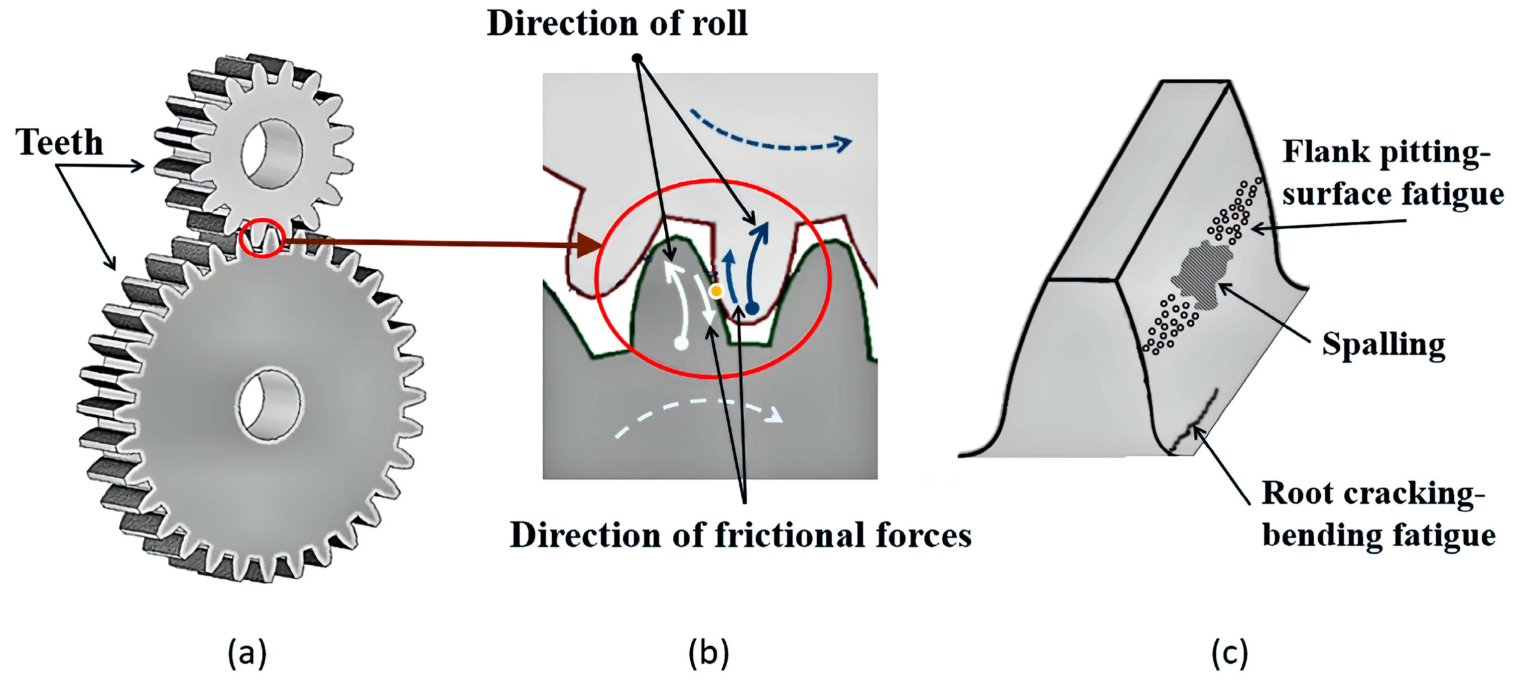
2.1. The Drawbacks of Mechanical Gears
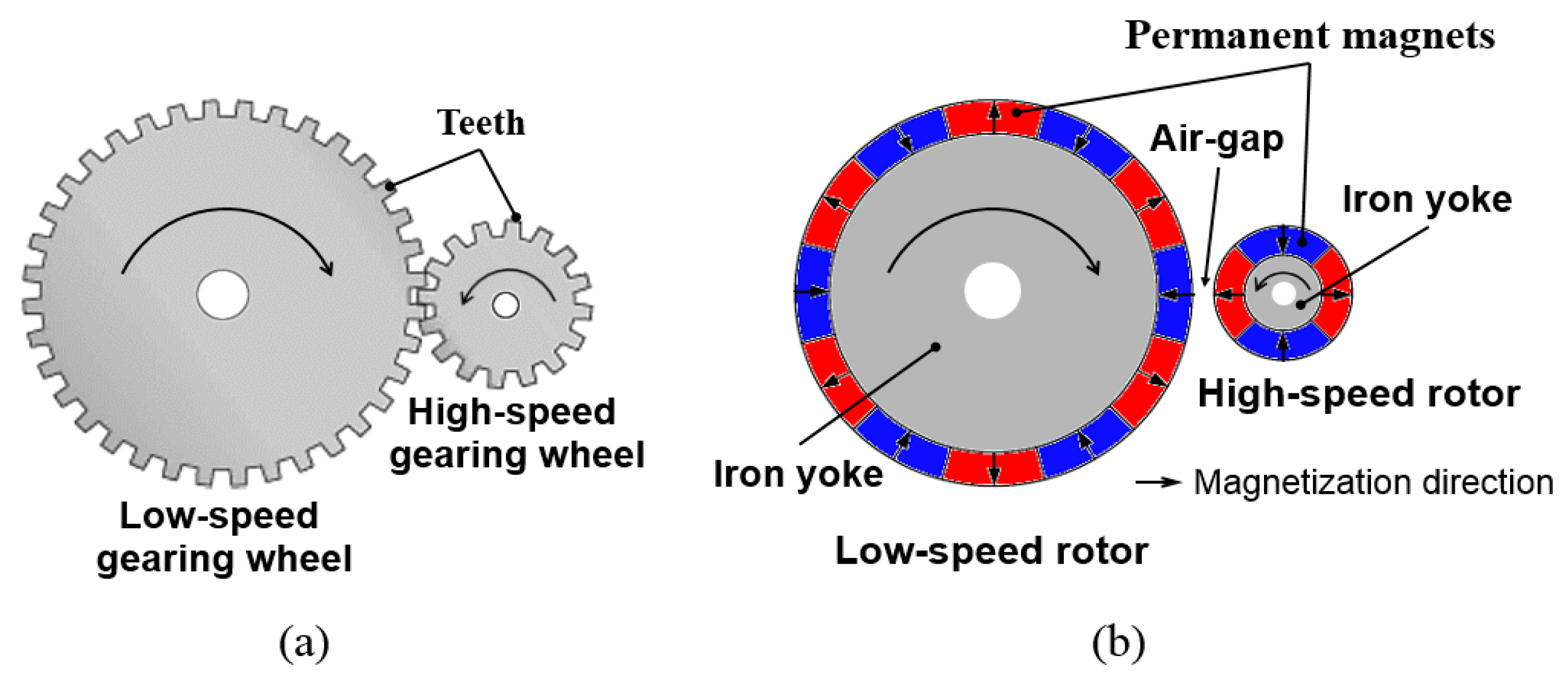
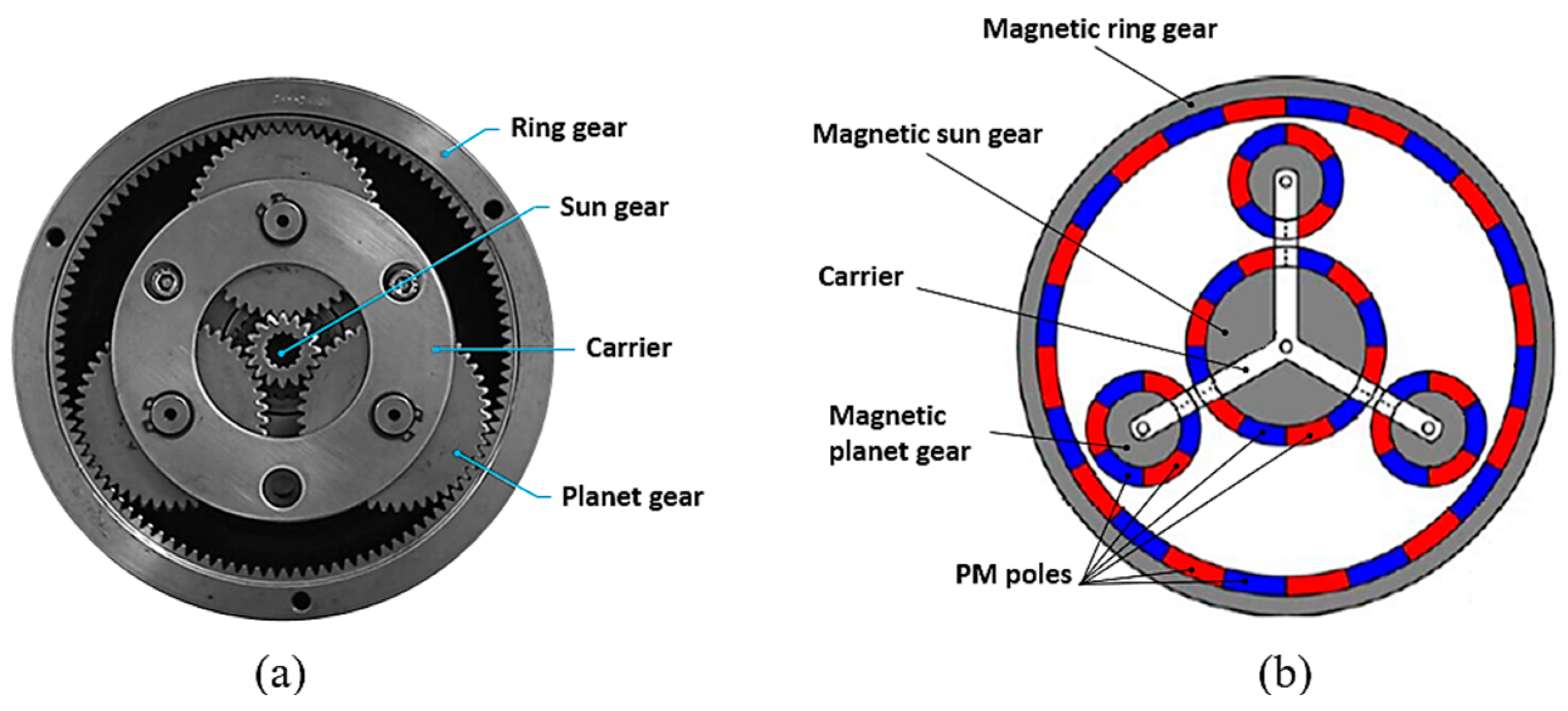
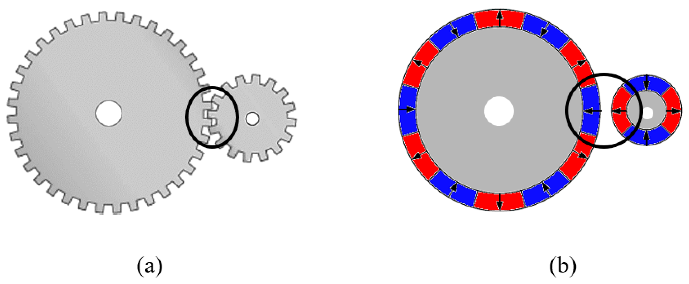
2.2. Conversion of Mechanical Gears into Magnetic Gears
2.3. Benefits of Magnetic Gear Technologies on Mechanical Power Transmission
- high reliability,
- high efficiency (torque densities comparable to mechanical gears can be achieved with a transmission efficiency >99% at full-load and with much higher partial-load efficiencies),
- high torque capacity (in some cases exceeding the values provided by its mechanical competitors),
- higher power ratings,
- compact size (a magnetic transmission will be smaller, lighter, and have a lower cost than a mechanical transmission),
- gear ratios of 50:1 down to 1.01:1, with almost zero torque ripple,
- physical isolation between input and output shafts,
- significant reduction in harmful drivetrain pulsations.
3. The State-of-the-Art Transmission Systems Based on Magnetic Gears Technologies
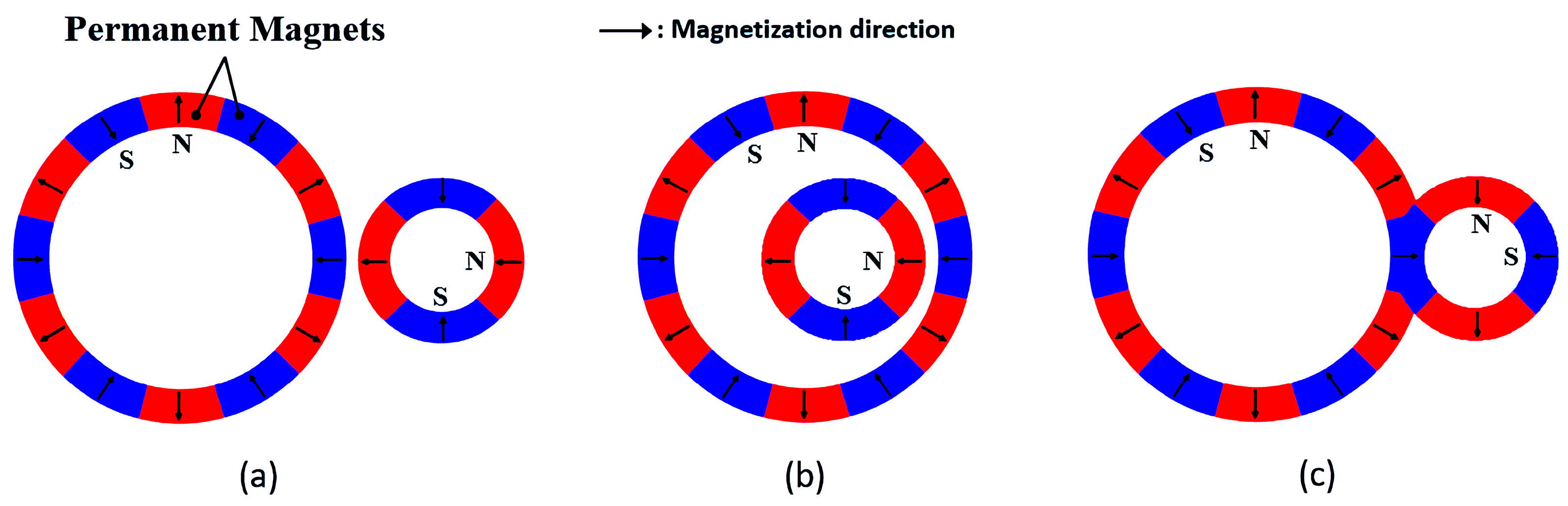
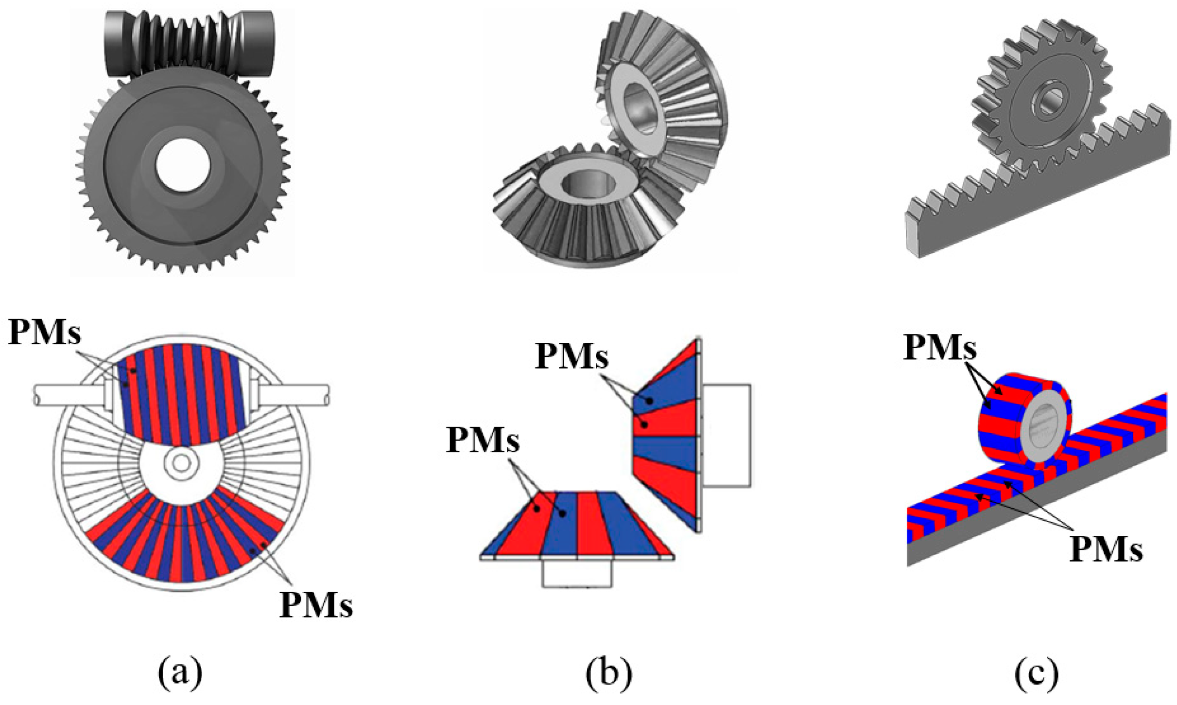
3.1. Early Topologies of Magnetic Gears
3.2. The Energy Sources in Magnetic Gears
3.3. Magnetic Gears with Higher Torque Density
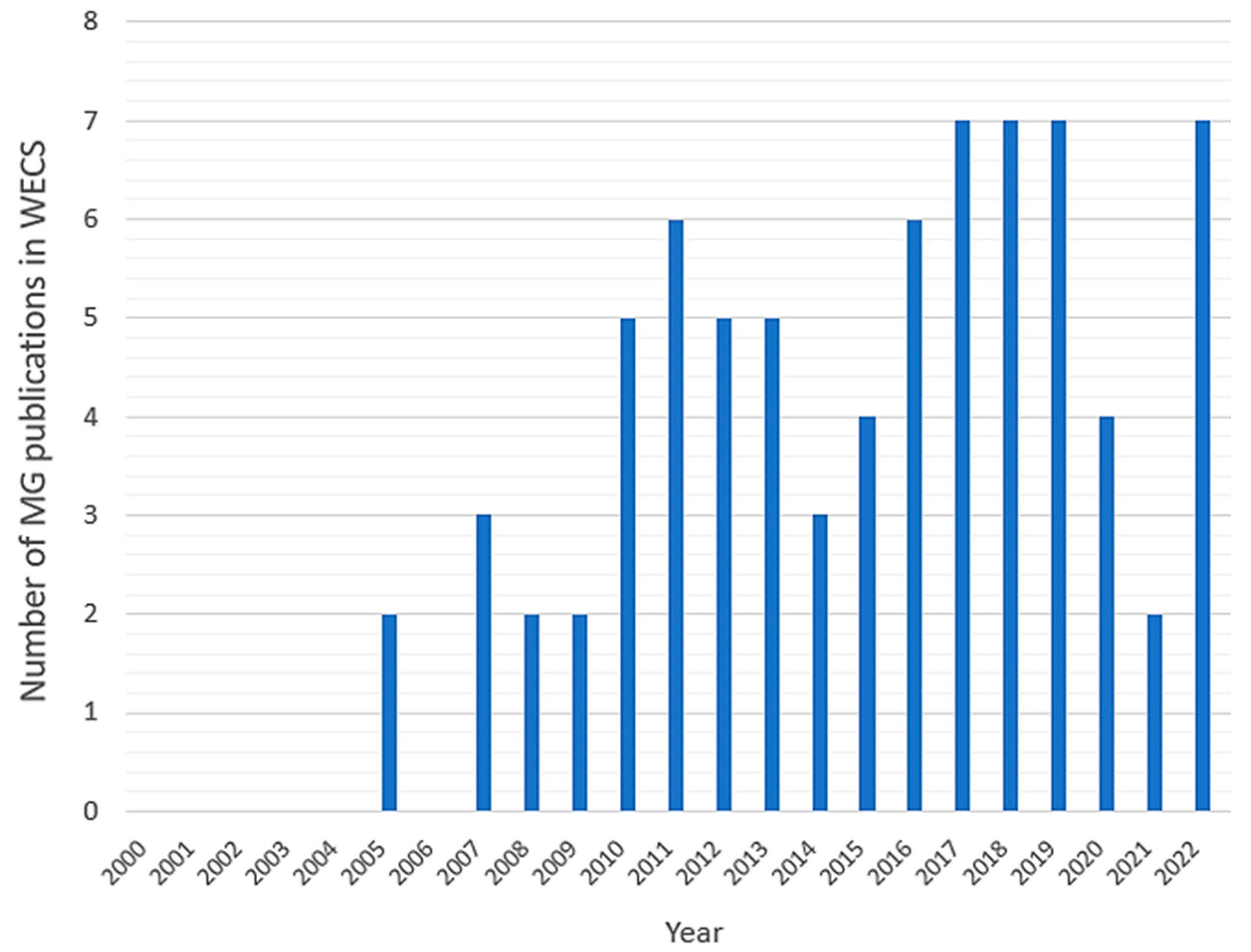
4. Magnetic Gears in WECSs

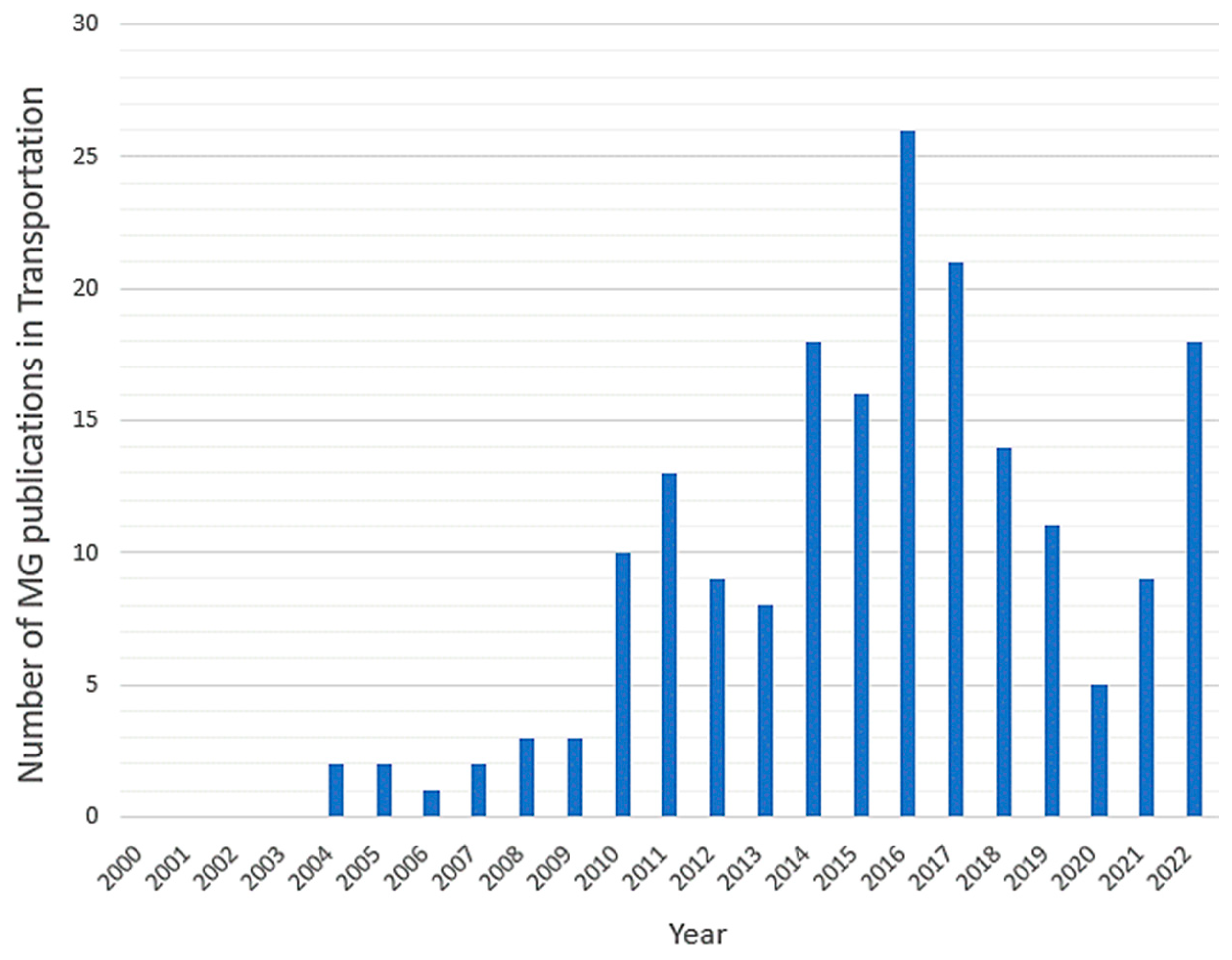
5. Magnetic Gears in Transportation (EVs)
6. Conclusions
Author Contributions
Funding
Data Availability Statement
Acknowledgments
Conflicts of Interest
References
- Ragheb, A.; Ragheb, M. Wind Turbine Gearbox Technologies. In Proceedings of the 2010 1st International Nuclear & Renewable Energy Conference (INREC), Amman, Jordan, 21–24 March 2010; pp. 1–8. [Google Scholar]
- Han, Q.; Wei, J.; Han, Q.; Zhang, H. Dynamics and Vibration Analyses of Gearbox in Wind Turbine; Springer Singapore: Singapore, 2017; ISBN 978-981-10-2746-8. [Google Scholar]
- Hailu, H.N.; Redda, D.T. Design and Development of Power Transmission System for Green and Light Weight Vehicles: A Review. Open Mech. Eng. J. 2018, 12, 81–94. [Google Scholar] [CrossRef]
- Stokes, A. Manual Gearbox Design; Butterworth-Heinemann Ltd.: Oxford, UK, 1992. [Google Scholar]
- Tůma, J. Vehicle Gearbox Noise and Vibration: Measurement, Signal Analysis, Signal Processing and Noise Reduction Measures; Wiley: Hoboken, NJ, USA, 2014; Volume 9781118359419. [Google Scholar]
- Duchemin, M.; Collée, V. Profile Optimization of the Teeth of the Double Rackand-Pinion Gear Mechanism in the MCE-5 VCRi. In Proceedings of the International Gear Conference 2014, Lyon, France, 26–28 August 2014. [Google Scholar]
- Mobley, J. Trade Studies for a High Torque Density Planetary Gearbox. In Proceedings of the 41st Aerospace Mechanisms Symposium, Pasadena, CA, USA, 16 May 2012; pp. 155–160. [Google Scholar]
- Kapelevich, A.L.; Ananiev, V.M. Gear Transmission Density Maximization. In Proceedings of the ASME 2011 International Design Engineering Technical Conferences and Computers and Information in Engineering Conference, Washington, DC, USA, 1 January 2011; pp. 127–133. [Google Scholar]
- Ristivojević, M.; Lazović, T.; Vencl, A. Studying the Load Carrying Capacity of Spur Gear Tooth Flanks. Mech. Mach. Theory 2013, 59, 125–137. [Google Scholar] [CrossRef]
- Radzevich, S.P. Handbook of Practical Gear Design and Manufacture; CRC Press: Boca Raton, FL, USA, 2012; ISBN 9780429109065. [Google Scholar]
- Lagutin, S.; Sandler, A.; Gudov, E. Actual Issues of Design and Production of Advanced Worm Gears. In Advanced Gear Engineering; Springer: Berlin/Heidelberg, Germany, 2018; pp. 139–166. [Google Scholar]
- Lehtovaara, A.; Szanti, G. Gears with extra high torque density. In BSA—Breakthrough Steels; DIMECC Final Report 3/2017; DIMECC Publications Series No. 16 2014-2017; DIMECC: Tampere, Finland, 2017; pp. 66–76. [Google Scholar]
- Goldfarb, V.; Barmina, N. Theory and Practice of Gearing and Transmissions; Goldfarb, V., Barmina, N., Eds.; Springer International Publishing: Cham, Switzerland, 2016; Volume 34, ISBN 978-3-319-19739-5. [Google Scholar]
- Muraro, M.A.; Koda, F.; Reisdorfer, U., Jr.; Silva, C.H. da The Influence of Contact Stress Distribution and Specific Film Thickness on the Wear of Spur Gears during Pitting Tests. J. Braz. Soc. Mech. Sci. Eng. 2012, 34, 135–144. [Google Scholar] [CrossRef]
- Smith, J.D. Gear Noise and Vibration; CRC Press: Boca Raton, FL, USA, 2003; ISBN 9781482276275. [Google Scholar]
- Jelaska, D. Gears and Gear Drives; Wiley: Hoboken, NJ, USA, 2012; ISBN 9781119941309. [Google Scholar]
- Dong, H.; Liu, Z.-Y.; Duan, L.; Hu, Y. Research on the Sliding Friction Associated Spur-Face Gear Meshing Efficiency Based on the Loaded Tooth Contact Analysis. PLoS ONE 2018, 13, e0198677. [Google Scholar] [CrossRef]
- Pedrero, J.I.; Pleguezuelos, M.; Sánchez, M.B. Study of the Influence of the Design Parameters on the Efficiency of Spur Gears. In Proceedings of the International Gear Conference 2014, Lyon, France, 26–28 August 2014. [Google Scholar]
- Concli, F.; Gorla, C. Analysis of the Power Losses in Geared Transmissions-Measurements and CFD Calculations Based on Open Source Codes. In Proceedings of the International Gear Conference 2014, Lyon, France, 26–28 August 2014. [Google Scholar]
- Choy, F.K.; Polyshchuk, V.; Zakrajsek, J.J.; Handschuh, R.F.; Townsend, D.P. Analysis of the Effects of Surface Pitting and Wear on the Vibration of a Gear Transmission System. Tribol. Int. 1996, 29, 77–83. [Google Scholar] [CrossRef]
- Ma, H.; Zeng, J.; Feng, R.; Pang, X.; Wang, Q.; Wen, B. Review on Dynamics of Cracked Gear Systems. Eng. Fail. Anal. 2015, 55, 224–245. [Google Scholar] [CrossRef]
- Abbes, M.S.; Fakhfakh, T.; Haddar, M.; Maalej, A. Effect of Transmission Error on the Dynamic Behaviour of Gearbox Housing. Int. J. Adv. Manuf. Technol. 2007, 34, 211–218. [Google Scholar] [CrossRef]
- Tuma, J. Gearbox Noise and Vibration Prediction and Control. Int. J. Acoust. Vib. 2009, 14, 99–108. [Google Scholar] [CrossRef]
- Montague, R. Control of Drive Trains Incorporating Magnetic Gears. Ph.D. Thesis, The University of Sheffield, Sheffield, UK, 2011. [Google Scholar]
- Magnomatics® Magnetic Gear Key Benefits, Magnomatics®, Technology, Magnetic Gears. Available online: http://www.magnomatics.com/pages/technology/low-ratio-magnetic-gears.htm (accessed on 21 January 2023).
- Faus, H.T. Magnetic Gearing. U.S. Patent 2243555, 27 May 1941. [Google Scholar]
- Ikuta, K.; Makita, S.; Arimoto, S. Non-Contact Magnetic Gear for Micro Transmission Mechanism. In Proceedings of the IEEE Micro Electro Mechanical Systems, Nara, Japan, 30 December–2 January 1991; pp. 125–130. [Google Scholar]
- Li, X.; Chau, K.-T.; Cheng, M.; Hua, W. Comparison of Magnetic-Geared Permanent-Magnet Machines. Prog. Electromagn. Res. 2013, 133, 177–198. [Google Scholar] [CrossRef]
- Furlani, E.P. A Two-Dimensional Analysis for the Coupling of Magnetic Gears. IEEE Trans. Magn. 1997, 33, 2317–2321. [Google Scholar] [CrossRef]
- Yao, Y.D.; Huang, D.R.; Lee, C.M.; Wang, S.J.; Chiang, D.Y.; Ying, T.F. Magnetic Coupling Studies between Radial Magnetic Gears. IEEE Trans. Magn. 1997, 33, 4236–4238. [Google Scholar] [CrossRef]
- Yao, Y.D.; Huang, D.R.; Hsieh, C.C.; Chiang, D.Y.; Wang, S.J. Simulation Study of the Magnetic Coupling between Radial Magnetic Gears. IEEE Trans. Magn. 1997, 33, 2203–2206. [Google Scholar] [CrossRef]
- Furlani, E.P. Analytical Analysis of Magnetically Coupled Multipole Cylinders. J. Phys. D Appl. Phys. 2000, 33, 28–33. [Google Scholar] [CrossRef]
- Charpentier, J.F.; Lemarquand, G. Mechanical Behavior of Axially Magnetized Permanent-Magnet Gears. IEEE Trans. Magn. 2001, 37, 1110–1117. [Google Scholar] [CrossRef]
- Okano, M.; Tsurumoto, K.; Togo, S.; Tamada, N.; Fuchino, S. Characteristics of the Magnetic Gear Using a Bulk High-Tc Superconductor. IEEE Trans. Appl. Supercond. 2002, 12, 979–983. [Google Scholar] [CrossRef]
- Yang, H.; Yang, Z.; Zhao, H. The FEM Analysis and Torque Calculation of REPM Gear. Phys. Stat. Sol. A 2002, 189, 1057–1061. [Google Scholar] [CrossRef]
- Rizk, J.; Nagrial, M.H.; Hellany, A. Analysis and Design of Magnetic Torque Couplers and Magnetic Gears. In Proceedings of the Conference Proceedings-IPEMC 2004: 4th International Power Electronics and Motion Control Conference, Xi’an, China, 14–16 August 2004; Volume 3. [Google Scholar]
- Jorgensen, F.T.; Andersen, T.O.; Rasmussen, P.O. Two Dimmensional Model of a Permanent Magnet Spur Gear-A Mathematical Method Used to Model a Parallel Magnetised. In Proceedings of the Fourtieth IAS Annual Meeting. Conference Record of the 2005 Industry Applications Conference, Hong Kong, China, 2–6 October 2005; pp. 261–265. [Google Scholar]
- Muruganandam, G.; Padma, S.; Selvakumar, P. Torque Analysis of Magnetic Spur Gear with Different Configurations. Int. J. Electr. Eng. 2012, 5, 843–852. [Google Scholar]
- Min, K.; Choi, J.; Cho, H.; Shin, H. Torque Analysis of Magnetic Spur Gear with Halbach Magnetized Permanent Magnets Using an Analytical Method. In Proceedings of the 2015 IEEE Magnetics Conference (INTERMAG), Beijing, China, 11–15 May 2015; p. 1. [Google Scholar]
- Wu, Y.C.; Wang, C.W. Transmitted Torque Analysis of a Magnetic Gear Mechanism with Rectangular Magnets. Appl. Math. Inf. Sci. 2015, 9, 1059–1065. [Google Scholar] [CrossRef]
- Aiso, K.; Akatsu, K.; Aoyama, Y. A Novel Magnetic Multiple Spur Gear for High Speed Motor System. In Proceedings of the 2018 IEEE Energy Conversion Congress and Exposition (ECCE), Portland, OR, USA, 23–27 September 2018; pp. 3310–3316. [Google Scholar]
- Bang, T.-K.; Shin, K.-H.; Koo, M.-M.; Han, C.; Cho, H.-W.; Choi, J.-Y. Measurement and Torque Calculation of Magnetic Spur Gear Based on Quasi 3-D Analytical Method. IEEE Trans. Appl. Supercond. 2018, 28, 1–5. [Google Scholar] [CrossRef]
- Baermann, M. Magnetic Worm Drive. U.S. Patent 3814962, 4 June 1974. [Google Scholar]
- Kikuchi, S.; Tsurumoto, K. Design and Characteristics of a New Magnetic Worm Gear Using Permanent Magnet. IEEE Trans. Magn. 1993, 29, 2923–2925. [Google Scholar] [CrossRef]
- Tsurumoto, K. Improvement of the Transmitted Torque Characteristics of a Magnetic Bevel Gear. J. Magn. Soc. Jpn. 1994, 18, 563–566. [Google Scholar] [CrossRef]
- Tsurumoto, K. Analysis of the Reversible Rotation and Power-Transmitting Performance of a Magnetic Bevel Gear. J. Magn. Soc. Jpn. 1997, 21, 821–824. [Google Scholar] [CrossRef]
- Yao, Y.D.; Huang, D.R.; Hsieh, C.C.; Chiang, D.Y.; Wang, S.J.; Ying, T.F. The Radial Magnetic Coupling Studies of Perpendicular Magnetic Gears. IEEE Trans. Magn. 1996, 32, 5061–5063. [Google Scholar] [CrossRef]
- Muruganandam, G.; Padma, S.; Selvakumar, P. Design and Implementation of a Novel Magnetic Bevel Gear. Control. Eng. Appl. Inform. 2013, 15, 30–37. [Google Scholar]
- Leas, M.F. Magnetic Spiral Bevel Gear. U.S. Patent 2016/0380525 A1, 29 December 2016. [Google Scholar]
- Jang, G.-H.; Kim, C.-W.; Seo, S.-W.; Shin, K.-H.; Yoon, I.-J.; Choi, J.-Y. Torque Characteristic Analysis and Measurement of Magnetic Rack–Pinion Gear Based on Analytical Method. IEEE Trans. Magn. 2019, 55, 1–5. [Google Scholar] [CrossRef]
- Tsurumoto, K.; Haneda, M.; Yamanaka, K.; Oikawa, Y.; Chiba, T. Performance Characteristics of Magnetic Planetary and Differential Gears for Accelerators in Which the Whole Depth of Outring Gear Has Been Corrected. J. Magn. Soc. Jpn. 2006, 30, 264–267. [Google Scholar] [CrossRef]
- Jørgensen, F.T. Design and Construction of Permanent Magnetic Gears. Ph.D. Thesis, Aalborg University, Aalborg, Denmark, 2010. [Google Scholar]
- Tsurumoto, K.; Tanaka, Y. Prototype Production of New Magnetic Planetary and Differential Gears and Performance Characteristics Test. J. Magn. Soc. Jpn. 2002, 26, 703–706. [Google Scholar] [CrossRef]
- Yamanaka, K.; Tsurumoto, K. Improvement of Performance Characteristics of Magnetic Planetary and Differential Gearing with Twin Sun Gears. J. Magn. Soc. Jpn. 2007, 31, 139–142. [Google Scholar] [CrossRef]
- Haneda, M.; Tsurumoto, K. Trial Production and Research on Magnetic Planetary and Differential Gearing for Accelerator Using NdFeB Magnet. J. Magn. Soc. Jpn. 2007, 31, 135–138. [Google Scholar] [CrossRef]
- Togashi, T.; Ota, Y.; Miyazawa, M.; Saito, O.; Tsurumoto, K. A Study of Output Speed Stability Control Using the Magnetic Planetary Gears with the Functional 2 Inputs. J. Magn. Soc. Jpn. 2012, 36, 263–267. [Google Scholar] [CrossRef]
- Huang, C.-C.; Tsai, M.-C.; Dorrell, D.G.; Lin, B.-J. Development of a Magnetic Planetary Gearbox. IEEE Trans. Magn. 2008, 44, 403–412. [Google Scholar] [CrossRef]
- Constantinides, S. The Demand for Rare Earth Materials in Permanent Magnets. In Proceedings of the 51st Annual Conference of Metallurgists, Arnold Magnetics (Rochester, New York, USA), Niagara Falls, ON, Canada, 30 September 2012. [Google Scholar]
- Chen, M.; Chau, K.-T.; Lee, C.H.T.; Liu, C. Design and Analysis of a New Axial-Field Magnetic Variable Gear Using Pole-Changing Permanent Magnetcs. Prog. Electromagn. Res. 2015, 153, 23–32. [Google Scholar] [CrossRef]
- Croat, J.J. Rapidly Solidified Neodymium-Iron-Boron Permanent Magnets; Elsevier: Amsterdam, The Netherlands, 2018; ISBN 9780081022252. [Google Scholar]
- Huang, C.-C. Power Magnetic Planetary Gear Set. U.S. Patent 8810099B2, 19 August 2014. [Google Scholar]
- Tsai, M.-C.; Huang, C.-C. Development of a Variable-Inertia Device with a Magnetic Planetary Gearbox. IEEE/ASME Trans. Mechatron. 2011, 16, 1120–1128. [Google Scholar] [CrossRef]
- Niguchi, N.; Hirata, K. Transmission Torque Analysis of a Novel Magnetic Planetary Gear Employing 3-D FEM. IEEE Trans. Magn. 2012, 48, 1043–1046. [Google Scholar] [CrossRef]
- Kong, F.; Ge, Y.; Zhu, X.; Qiao, L.; Quan, L. Optimizing Design of Magnetic Planetary Gearbox for Reduction of Cogging Torque. In Proceedings of the 2013 IEEE Vehicle Power and Propulsion Conference (VPPC), Beijing, China, 15–18 October 2013; pp. 1–5. [Google Scholar]
- Niguchi, N.; Hirata, K.; Sakai, M. High Performance Hybrid-Type Magnetic Planetary Gear. In Proceedings of the 2013 IEEE International Conference on Mechatronics and Automation, Takamatsu, Japan, 4–7 August 2013; pp. 662–669. [Google Scholar]
- Zhang, R.; Zhu, X.; Chen, L. Design of a New Magnetic-Planetary-Geared Outer-Rotor Permanent-Magnet Brushless Motor for Electric Vehicles. In Proceedings of the 2014 17th International Conference on Electrical Machines and Systems (ICEMS), Hangzhou, China, 22–25 October 2014; pp. 658–663. [Google Scholar]
- Frandsen, T.V. Motor Integrated Permanent Magnet Gear. Ph.D. Thesis, Aalborg University, Aalborg, Denmark, 2016. [Google Scholar]
- Atallah, K.; Howe, D. A Novel High-Performance Magnetic Gear. IEEE Trans. Magn. 2001, 37, 2844–2846. [Google Scholar] [CrossRef]
- Neuland, A.H. Apparatus for Transmitting Power. U.S. Patent 1171351, 8 February 1916. [Google Scholar]
- Reese, G.A. Magnetic Gearing Arrangement. U.S. Patent 3301091, 31 January 1967. [Google Scholar]
- Martin, T.B. Magnetic Transmission. U.S. Patent 3378710, 16 April 1968. [Google Scholar]
- Gerber, S. Evaluation and Design Aspects of Magnetic Gears and Magnetically Geared Electrical Machines. Ph.D. Thesis, Stellenbosch University, Matieland, South Africa, 2015. [Google Scholar]
- Frank, N.W. Analysis of the Concentric Planetary Magnetic Gear. Ph.D. Thesis, Texas A&M University, College Station, TX, USA, 2011. [Google Scholar]
- Molokanov, O.; Kurbatov, P.; Dergachev, P.; Alami, A. Dynamic Model of Coaxial Magnetic Planetary Gear. In Proceedings of the 2015 18th International Conference on Electrical Machines and Systems (ICEMS), Pattaya, Thailand, 25–28 October 2015; pp. 944–948. [Google Scholar]
- Atallah, K.; Calverley, S.D.; Howe, D. Design, Analysis and Realisation of a High-Performance Magnetic Gear. IEE Proc.-Electr. Power Appl. 2004, 151, 135. [Google Scholar] [CrossRef]
- Gardner, M.C.; Jack, B.E.; Johnson, M.; Toliyat, H.A. Comparison of Surface Mounted Permanent Magnet Coaxial Radial Flux Magnetic Gears Independently Optimized for Volume, Cost, and Mass. IEEE Trans. Ind. Appl. 2018, 54, 2237–2245. [Google Scholar] [CrossRef]
- Jian, L.; Chau, K.T.; Gong, Y.; Jiang, J.Z.; Yu, C.; Li, W. Comparison of Coaxial Magnetic Gears with Different Topologies. IEEE Trans. Magn. 2009, 45, 4526–4529. [Google Scholar] [CrossRef]
- Li, X.; Chau, K.T.; Cheng, M.; Hua, W.; Du, Y. An Improved Coaxial Magnetic Gear Using Flux Focusing. In Proceedings of the 2011 International Conference on Electrical Machines and Systems, Beijing, China, 20–23 August 2011; pp. 1–4. [Google Scholar]
- Atallah, K.; Wang, J.; Howe, D. A High-Performance Linear Magnetic Gear. J. Appl. Phys. 2005, 97, 10N516. [Google Scholar] [CrossRef]
- Holehouse, R.C.; Atallah, K.; Wang, J. Design and Realization of a Linear Magnetic Gear. IEEE Trans. Magn. 2011, 47, 4171–4174. [Google Scholar] [CrossRef]
- Li, W.; Chau, K.T.; Jiang, J.Z. Application of Linear Magnetic Gears for Pseudo-Direct-Drive Oceanic Wave Energy Harvesting. IEEE Trans. Magn. 2011, 47, 2624–2627. [Google Scholar] [CrossRef]
- Feng, N.; Yu, H.; Huang, L.; Zhong, W.; Shi, Z. Performance Analysis of a Magnetic-Geared Linear Permanent Magnet Generator for Wave Energy Conversion. In Proceedings of the 2015 IEEE Magnetics Conference (INTERMAG), Beijing, China, 11–15 May 2015; p. 1. [Google Scholar]
- Li, W.; Chau, K.T.; Lee, C.H.T.; Ching, T.W.; Chen, M.; Jiang, J.Z. A New Linear Magnetic Gear with Adjustable Gear Ratios and Its Application for Direct-Drive Wave Energy Extraction. Renew. Energy 2017, 105, 199–208. [Google Scholar] [CrossRef]
- Liu, C.; Zhu, H.; Dong, R.; Zhou, S.; Huang, L. Sensitivity Analysis and Optimal Design of a Linear Magnetic Gear for Direct-Drive Wave Energy Conversion. IEEE Access 2019, 7, 73983–73992. [Google Scholar] [CrossRef]
- Mezani, S.; Atallah, K.; Howe, D. A High-Performance Axial-Field Magnetic Gear. J. Appl. Phys. 2006, 99, 08R303. [Google Scholar] [CrossRef]
- Rasmussen, P.O.; Andersen, T.O.; Jørgensen, F.T.; Nielsen, O. Development of a High-Performance Magnetic Gear. IEEE Trans. Ind. Appl. 2005, 41, 764–770. [Google Scholar] [CrossRef]
- Uppalapati, K.K.; Bird, J.Z.; Wright, J.; Pitchard, J.; Calvin, M.; Williams, W. A Magnetic Gearbox with an Active Region Torque Density of 239Nm/L. In Proceedings of the 2014 IEEE Energy Conversion Congress and Exposition, ECCE 2014, Pittsburgh, PA, USA, 14–18 September 2014. [Google Scholar]
- Halbach, K. Design of Permanent Multipole Magnets with Oriented Rare Earth Cobalt Material. Nucl. Instrum. Methods 1980, 169, 1–10. [Google Scholar] [CrossRef]
- Choi, J.-S.; Yoo, J. Design of a Halbach Magnet Array Based on Optimization Techniques. IEEE Trans. Magn. 2008, 44, 2361–2366. [Google Scholar] [CrossRef]
- Jian, L.; Chau, K.T. A Coaxial Magnetic Gear with Halbach Permanent-Magnet Arrays. IEEE Trans. Energy Convers. 2010, 25, 319–328. [Google Scholar] [CrossRef]
- Fujita, T.; Ando, Y.; Nagaya, K.; Oka, M.; Todaka, T.; Enokizono, M.; Sugiura, K. Surface Magnet Gears with a New Magnet Arrangement and Optimal Shape of Stationary Pole Pieces. J. Electromagn. Anal. Appl. 2013, 05, 243–249. [Google Scholar] [CrossRef]
- Som, D.; Li, K.; Kadel, J.; Wright, J.; Modaresahmadi, S.; Bird, J.Z.; William, W. Analysis and Testing of a Coaxial Magnetic Gearbox with Flux Concentration Halbach Rotors. IEEE Trans. Magn. 2017, 53, 1–6. [Google Scholar] [CrossRef]
- Liu, X.; Chau, K.T.; Jiang, J.Z.; Yu, C. Design and Analysis of Interior-Magnet Outer-Rotor Concentric Magnetic Gears. J. Appl. Phys. 2009, 105, 07F101. [Google Scholar] [CrossRef]
- Shen, J.-X.; Li, H.-Y.; Hao, H.; Jin, M.-J. A Coaxial Magnetic Gear with Consequent-Pole Rotors. IEEE Trans. Energy Convers. 2017, 32, 267–275. [Google Scholar] [CrossRef]
- Jing, L.; Gong, J.; Huang, Z.; Ben, T.; Huang, Y. A New Structure for the Magnetic Gear. IEEE Access 2019, 7, 75550–75555. [Google Scholar] [CrossRef]
- Frank, N.W.; Toliyat, H.A. Analysis of the Concentric Planetary Magnetic Gear with Strengthened Stator and Interior Permanent Magnet Inner Rotor. IEEE Trans. Ind. Appl. 2011, 47, 1652–1660. [Google Scholar] [CrossRef]
- Frank, N.W.; Pakdelian, S.; Toliyat, H.A. Passive Suppression of Transient Oscillations in the Concentric Planetary Magnetic Gear. IEEE Trans. Energy Convers. 2011, 26, 933–939. [Google Scholar] [CrossRef]
- Abdel-Khalik, A.S.; Ahmed, S.; Massoud, A. A Bearingless Coaxial Magnetic Gearbox. Alex. Eng. J. 2014, 53, 573–582. [Google Scholar] [CrossRef]
- Liu, Y.; Ho, S.L.; Fu, W.N. A Novel Magnetic Gear with Intersecting Axes. IEEE Trans. Magn. 2014, 50, 1–4. [Google Scholar] [CrossRef]
- Aiso, K.; Akatsu, K. A Novel Reluctance Magnetic Gear for High Speed Motor. In Proceedings of the 2016 IEEE Energy Conversion Congress and Exposition (ECCE), Milwaukee, WI, USA, 18–22 September 2016; pp. 1–7. [Google Scholar]
- Yong, L.; Jingwei, X.; Kerong, P.; Yongping, L. Principle and Simulation Analysis of a Novel Structure Magnetic Gear. In Proceedings of the Proceedings of the 11th International Conference on Electrical Machines and Systems, Wuhan, China, 17–20 October 2008. [Google Scholar]
- Bomela, W.; Bird, J.Z.; Acharya, V.M. The Performance of a Transverse Flux Magnetic Gear. IEEE Trans. Magn. 2014, 50, 1–4. [Google Scholar] [CrossRef]
- Desvaux, M.; Chauwin, M.; Multon, B.; Sire, S.; ben Ahmed, H. Experimental Validation of a Transverse Flux Magnetic Gear. J. Magn. Magn. Mater. 2021, 536, 168139. [Google Scholar] [CrossRef]
- Bang, D.; Polinder, H.; Shrestha, G.; Ferreira, J.A. Ring-Shaped Transverse Flux PM Generator for Large Direct-Drive Wind Turbines. In Proceedings of the 2009 International Conference on Power Electronics and Drive Systems (PEDS), Taipei, Taiwan, 2–5 November 2009; pp. 61–66. [Google Scholar]
- Hasan, I.; Husain, T.; Uddin, M.W.; Sozer, Y.; Husain, I.; Muljadi, E. Analytical Modeling of a Novel Transverse Flux Machine for Direct Drive Wind Turbine Applications. In Proceedings of the 2015 IEEE Energy Conversion Congress and Exposition (ECCE), Montreal, QC, Canada, 20–24 September 2015; pp. 2161–2168. [Google Scholar]
- Peng, G.; Wei, J.; Shi, Y.; Shao, Z.; Jian, L. A Novel Transverse Flux Permanent Magnet Disk Wind Power Generator with H-Shaped Stator Cores. Energies 2018, 11, 810. [Google Scholar] [CrossRef]
- Ballestín-Bernad, V.; Artal-Sevil, J.S.; Domínguez-Navarro, J.A. A Review of Transverse Flux Machines Topologies and Design. Energies 2021, 14, 7173. [Google Scholar] [CrossRef]
- Pakdelian, S.; Frank, N.W.; Toliyat, H.A. Analysis and Design of the Trans-Rotary Magnetic Gear. In Proceedings of the 2012 IEEE Energy Conversion Congress and Exposition (ECCE), Raleigh, CA, USA, 15–20 September 2012; pp. 3340–3347. [Google Scholar]
- Pakdelian, S.; Deshpande, Y.; Toliyat, H.A. An Electric Machine Integrated with Trans-Rotary Magnetic Gear. In Proceedings of the 2012 IEEE Energy Conversion Congress and Exposition (ECCE), Raleigh, CA, USA, 15–20 September 2012; pp. 3356–3362. [Google Scholar]
- Pakdelian, S.; Toliyat, H.A. Design Aspects of the Trans-Rotary Magnetic Gear. In Proceedings of the IECON 2012-38th Annual Conference on IEEE Industrial Electronics Society, Montreal, QC, Canada, 25–28 October 2012; pp. 1720–1725. [Google Scholar]
- Pakdelian, S.; Frank, N.W.; Toliyat, H.A. Principles of the Trans-Rotary Magnetic Gear. IEEE Trans. Magn. 2013, 49, 883–889. [Google Scholar] [CrossRef]
- Pakdelian, S.; Toliyat, H.A. Trans-Rotary Magnetic Gear for Wave Energy Applicaion. In Proceedings of the 2012 IEEE Power and Energy Society General Meeting, San Diego, CA, USA, 22–26 July 2012; pp. 1–4. [Google Scholar]
- Pakdelian, S.; Toliyat, H.A. Dynamic Modeling of the Trans-Rotary Magnetic Gear for the Point-Absorbing Wave Energy Conversion Systems. In Proceedings of the 2014 IEEE Energy Conversion Congress and Exposition (ECCE), Pittsburgh, PA, USA, 4–18 September 2014; pp. 3163–3170. [Google Scholar]
- Rens, J.; Clark, R.; Calverley, S.; Atallah, K.; Howe, D. Design, Analysis and Realization of a Novel Magnetic Harmonic Gear. In Proceedings of the Proceedings of the 2008 International Conference on Electrical Machines, Vilamoura, Portugal, 6–9 September 2008. [Google Scholar]
- Rens, J.; Atallah, K.; Calverley, S.D.; Howe, D. A Novel Magnetic Harmonic Gear. IEEE Trans. Ind. Appl. 2010, 46, 206–212. [Google Scholar] [CrossRef]
- Jorgensen, F.T.; Andersen, T.O.; Rasmussen, P.O. The Cycloid Permanent Magnetic Gear. IEEE Trans. Ind. Appl. 2008, 44, 1659–1665. [Google Scholar] [CrossRef]
- Fo-Lyn, M.C.; Primero, Y.; Uziel, R.C. Modelo Cinemático de Reductor Cicloidal Magnético. Ing. Mecánica. Tecnol. Y Desarro. 2017, 6, 25–29. [Google Scholar]
- Uziel, R.C. Transmisiones de Engranes Magnéticos. Gaceta del IIUNAM 2017, 126, 5–6. Available online: http://gacetaii.iingen.unam.mx/GacetaII/index.php/gii/issue/view/135/Gaceta%20126 (accessed on 30 January 2023).
- Gardner, M.C.; Johnson, M.; Toliyat, H.A. Comparison of Surface Permanent Magnet Coaxial and Cycloidal Radial Flux Magnetic Gears. In Proceedings of the 2018 IEEE Energy Conversion Congress and Exposition (ECCE), Portland, OR, USA, 23–27 September 2018; pp. 5005–5012. [Google Scholar]
- Gieras, J.F. Permanent Magnet Motor Technology: Design and Applications, 3rd ed.; CRC Press, Taylor & Francis Group: Boca Raton, FL, USA, 2010. [Google Scholar]
- Jian, L.; Xu, G.; Gong, Y.; Song, J.; Liang, J.; Chang, M. Electromagnetic Design Analysis of a Novel Magnetic-Gear-Integrated Wind Power Generator Using Time-Stepping Finite Element Method. Prog. Electromagn. Res. 2011, 113, 351–367. [Google Scholar] [CrossRef]
- Jian, L.; Chau, K.T.; Jiang, J.Z. A Magnetic-Geared Outer-Rotor Permanent-Magnet Brushless Machine for Wind Power Generation. IEEE Trans. Ind. Appl. 2009, 45, 954–962. [Google Scholar] [CrossRef]
- Atallah, K.; Wang, J.; Calverley, S.D.; Duggan, S. Design and Operation of a Magnetic Continuously Variable Transmission. IEEE Trans. Ind. Appl. 2012, 48, 1288–1295. [Google Scholar] [CrossRef]
- Abdelhamid, D.Z.; Knight, A.M. Performance of a High Torque Density Induction Motor with an Integrated Magnetic Gear. In Proceedings of the 2016 XXII International Conference on Electrical Machines (ICEM), Lausanne, Switzerland, 4–7 September 2016; pp. 538–544. [Google Scholar]
- Zhu, Z.Q.; Li, H.Y.; Deodhar, R.; Pride, A.; Sasaki, T. Recent Developments and Comparative Study of Magnetically Geared Machines. CES Trans. Electr. Mach. Syst. 2018, 2, 13–22. [Google Scholar] [CrossRef]
- Atallah, K.; Rens, J.; Mezani, S.; Howe, D. A Novel “Pseudo” Direct-Drive Brushless Permanent Magnet Machine. IEEE Trans. Magn. 2008, 44, 4349–4352. [Google Scholar] [CrossRef]
- Bouheraoua, M.; Wang, J.; Atallah, K. Rotor Position Estimation of a Pseudo Direct Drive PM Machine Using Extended Kalman Filter. In Proceedings of the 2015 IEEE Energy Conversion Congress and Exposition (ECCE), Montreal, QC, Canada, 20–24 September 2015; pp. 292–299. [Google Scholar]
- Magnomatics® Pseudo Direct Drive. Available online: https://www.magnomatics.com/pseudo-direct-drive (accessed on 21 January 2023).
- Magnomatics® Wind Turbine Generator. Available online: https://www.magnomatics.com/post/wind-turbine-generator (accessed on 21 January 2023).
- Bao, G.Q.; Mao, K.F. A Wind Energy Conversion System with Field Modulated Magnetic Gear. In Proceedings of the 2011 Asia-Pacific Power and Energy Engineering Conference, Wuhan, China, 25–28 March 2011; pp. 1–4. [Google Scholar]
- Penzkofer, A.; Atallah, K. Analytical Modeling and Optimization of Pseudo-Direct Drive Permanent Magnet Machines for Large Wind Turbines. IEEE Trans. Magn. 2015, 51, 1–14. [Google Scholar] [CrossRef]
- Neves, C.G.C.; Flores Filho, A.F.; Dorrel, D.G. Design of a Pseudo Direct Drive for Wind Power Applications. In Proceedings of the 2016 International Conference of Asian Union of Magnetics Societies (ICAUMS), Tainan, Taiwan, 1–5 August 2016; pp. 1–5. [Google Scholar]
- Tlali, P.M.; Gerber, S.; Wang, R.-J. Optimal Design of an Outer-Stator Magnetically Geared Permanent Magnet Machine. IEEE Trans. Magn. 2016, 52, 1–10. [Google Scholar] [CrossRef]
- Penzkofer, A.; Atallah, K. Scaling of Pseudo Direct Drives for Wind Turbine Application. IEEE Trans. Magn. 2016, 52, 1–5. [Google Scholar] [CrossRef]
- Desmedt, M.; Dong, J.; Wani, F.; Bauer, P.; Polinder, H. Electromechanical Dynamics Analysis of Pole-Piece Rotors in Pseudo Direct-Drive Wind Turbine Generators. In Proceedings of the 2020 International Conference on Electrical Machines (ICEM), Gothenburg, Sweden, 23–26 August 2020; pp. 1889–1895. [Google Scholar]
- Wang, Y.; Ho, S.L.; Fu, W.N.; Shen, J.X. A Novel Brushless Doubly Fed Generator for Wind Power Generation. IEEE Trans. Magn. 2012, 48, 4172–4175. [Google Scholar] [CrossRef]
- Vyas, P.; Waszak, M.-W. Magnetically Geared Generator. U.S. Patent 2010/0052323A1, 4 March 2010. [Google Scholar]
- Jiang, Y.; Zhang, J.; Li, T. A Segmented Brushless Doubly Fed Generator for Wind Power Applications. IEEE Trans. Magn. 2018, 54, 1–4. [Google Scholar] [CrossRef]
- Jian, L.; Liang, J.; Shi, Y.; Xu, G. A Novel Double-Winding Permanent Magnet FLux Modulated Machine for Stand-Alone Wind Power Generation. Prog. Electromagn. Res. 2013, 142, 275–289. [Google Scholar] [CrossRef]
- Li, X.; Chau, K.T.; Cheng, M. Analysis, Design and Experimental Verification of a Field-modulated Permanent-magnet Machine for Direct-drive Wind Turbines. IET Electr. Power Appl. 2015, 9, 150–159. [Google Scholar] [CrossRef]
- Fang, L.; Li, D.; Zou, T.; Qu, R. Flux Modulation Magnet Coupler for Wind Generation System. In Proceedings of the 2020 International Conference on Electrical Machines (ICEM), Gothenburg, Sweden, 23–26 August 2020; pp. 1992–1998. [Google Scholar]
- Desvaux, M.; Latimier, R.L.G.; Multon, B.; Ahmed, H.B.; Sire, S. Design and Optimization of Magnetic Gears with Arrangement and Mechanical Constraints for Wind Turbine Applications. In Proceedings of the 2016 Eleventh International Conference on Ecological Vehicles and Renewable Energies (EVER), Monte Carlo, Monaco, 6–8 April 2016; pp. 1–8. [Google Scholar]
- Wang, J.; Qian, L.; Xu, S.; Mo, R. Analysis of Electromagnetic Performance of Modulated Coaxial Magnetic Gears Used in Semi-Direct Drive Wind Turbines. Energy Eng. 2021, 118, 251–264. [Google Scholar] [CrossRef]
- Frank, N.W.; Toliyat, H.A. Gearing Ratios of a Magnetic Gear for Wind Turbines. In Proceedings of the 2009 IEEE International Electric Machines and Drives Conference, Miami, Fl, USA, 3–6 May 2009; pp. 1224–1230. [Google Scholar]
- Abdel-Khalik, A.S.; Elserougi, A.; Ahmed, S.; Massoud, A. A Wind Turbine Architecture Employing a New Three Port Magnetic Gear Box. In Proceedings of the 2012 IEEE Energy Conversion Congress and Exposition (ECCE), Raleigh, CA, USA, 15–20 September 2012; pp. 1917–1924. [Google Scholar]
- Belkhir, K.S.; Khenfer, N. Magnetic Gear Generator for Wind Energy. Prz. Elektrotechniczny 2013, 89, 72–75. [Google Scholar]
- Gouda, E. A New Design of Magnetic Gear for Wind Turbine. Bull. Fac. Engineering. Mansoura Univ. 2020, 39, 1–6. [Google Scholar] [CrossRef]
- Penzkofer, A.; Atallah, K. Optimisation of Magnetic Gears for Large Wind Turbines. In Proceedings of the 2015 IEEE 15th International Conference on Environment and Electrical Engineering (EEEIC), Rome, Italy, 10–13 June 2015; pp. 962–967. [Google Scholar]
- Desvaux, M.; le Goff Latimier, R.; Multon, B.; Sire, S.; ben Ahmed, H. Analysis of the Dynamic Behaviour of Magnetic Gear with Nonlinear Modelling for Large Wind Turbines. In Proceedings of the 2016 XXII International Conference on Electrical Machines (ICEM), Lausanne, Switzerland, 4–7 September 2016; pp. 1332–1338. [Google Scholar]
- Udalov, S.N.; Achitaev, A.A.; Pristup, A.G. Investigations of a Magnetic Gear for Application in Wind Turbines. In Proceedings of the 2016 11th International Forum on Strategic Technology (IFOST), Novosibirsk, Russia, 1–3 June 2016; pp. 166–171. [Google Scholar]
- Desvaux, M.; Multon, B.; Sire, S.; Ben Ahmed, H. Analytical Iron Loss Model for the Optimization of Magnetic Gear. In Proceedings of the 2017 IEEE International Electric Machines and Drives Conference (IEMDC), Miami, FL, USA, 21–24 May 2017; pp. 1–8. [Google Scholar]
- Desvaux, M.; Traulle, B.; le Goff Latimier, R.; Sire, S.; Multon, B.; ben Ahmed, H. Computation Time Analysis of the Magnetic Gear Analytical Model. IEEE Trans. Magn. 2017, 53, 1–9. [Google Scholar] [CrossRef]
- Li, K.; Wright, J.; Modaresahmadi, S.; Som, D.; Williams, W.; Bird, J.Z. Designing the First Stage of a Series Connected Multistage Coaxial Magnetic Gearbox for a Wind Turbine Demonstrator. In Proceedings of the 2017 IEEE Energy Conversion Congress and Exposition (ECCE), Cincinnati, OH, USA, 1–5 October 2017; pp. 1247–1254. [Google Scholar]
- Desvaux, M.; Multon, B.; Ahmed, H.B.; Sire, S.; Fasquelle, A.; Laloy, D. Gear Ratio Optimization of a Full Magnetic Indirect Drive Chain for Wind Turbine Applications. In Proceedings of the 2017 Twelfth International Conference on Ecological Vehicles and Renewable Energies (EVER), Monte Carlo, Monaco, 11–13 April 2017; pp. 1–9. [Google Scholar]
- Desvaux, M.; Multon, B.; Ahmed, H.B.; Sire, S. Magneto-Mechanical Sizing of Magnetic Gear Laminated Pole Pieces for Wind Turbine Applications. In Proceedings of the International Conference on Wind Energy Harvesting, Coimbra, Portugal, 20 March 2017. [Google Scholar]
- Desvaux, M.; Multon, B.; ben Ahmed, H.; Sire, S. Supporting the Laminated Ferromagnetic Pole Pieces in a Magnetic Gear: A Structure Behaviour Analysis from a Multibody Model. In Proceedings of the Mechanisms and Machine Science, Florianópolis, Brazil, 24–28 October 2018; Volume 54. [Google Scholar]
- Desvaux, M.; Bildstein, H.; Multon, B.; ben Ahmed, H.; Sire, S.; Fasquelle, A.; Laloy, D. Magnetic Losses and Thermal Analysis in a Magnetic Gear for Wind Turbine. In Proceedings of the 2018 Thirteenth International Conference on Ecological Vehicles and Renewable Energies (EVER), Monte Carlo, Monaco, 10–12 April 2018; pp. 1–7. [Google Scholar]
- Desvaux, M.; Multon, B.; Ahmed, H.B.; Sire, S. Magneto-Mechanical Analysis of Magnetic Gear Pole Pieces Ring from Analytical Models for Wind Turbine Applications. Wind. Eng. 2018, 42, 276–285. [Google Scholar] [CrossRef]
- Zeinali, R.; Keysan, O. A Rare-Earth Free Magnetically Geared Generator for Direct-Drive Wind Turbines. Energies 2019, 12, 447. [Google Scholar] [CrossRef]
- Kim, B. Design Method of a Direct-Drive Permanent Magnet Vernier Generator for a Wind Turbine System. IEEE Trans. Ind. Appl. 2019, 55, 4665–4675. [Google Scholar] [CrossRef]
- Fang, H.; Wang, Y.; Cai, X. Design of Magnetic Gear Integrated Generator with Mixed Magnetization and Eccentric Pole Method for Wave Energy Conversion. In Proceedings of the 2019 22nd International Conference on Electrical Machines and Systems (ICEMS), Harbin, China, 11–14 August 2019; pp. 1–6. [Google Scholar]
- Li, K.; Modaresahmadi, S.; Williams, W.B.; Wright, J.D.; Som, D.; Bird, J.Z. Designing and Experimentally Testing a Magnetic Gearbox for a Wind Turbine Demonstrator. IEEE Trans. Ind. Appl. 2019, 55, 3522–3533. [Google Scholar] [CrossRef]
- Li, K.; Modaresahmadi, S.; Williams, W.B.; Bird, J.Z.; Wright, J.D.; Barnett, D. Electromagnetic Analysis and Experimental Testing of a Flux Focusing Wind Turbine Magnetic Gearbox. IEEE Trans. Energy Convers. 2019, 34, 1512–1521. [Google Scholar] [CrossRef]
- Gaojia, Z.; Longnv, L. Design Optimization of a Direct-Drive PM Wind Generator with Flux-Modulation Structure. In Proceedings of the 2020 IEEE International Conference on Applied Superconductivity and Electromagnetic Devices (ASEMD), Tianjin, China, 16–18 October 2020; pp. 1–2. [Google Scholar]
- Feng, N.; Yu, H.; Hu, M.; Liu, C.; Huang, L.; Shi, Z. A Study on a Linear Magnetic-Geared Interior Permanent Magnet Generator for Direct-Drive Wave Energy Conversion. Energies 2016, 9, 487. [Google Scholar] [CrossRef]
- Liu, C.; Zhu, H.; Dong, R. Linear Magnetic Gear with HTS Bulks for Wave Energy Conversion. IET Renew. Power Gener. 2019, 13, 2430–2434. [Google Scholar] [CrossRef]
- Qu, R.; Li, D.; Wang, J. Relationship between Magnetic Gears and Vernier Machines. In Proceedings of the 2011 International Conference on Electrical Machines and Systems, Beijing, China, 20–23 August 2011; pp. 1–6. [Google Scholar]
- Wu, F.; El-Refaie, A.M. Permanent Magnet Vernier Machine: A Review. IET Electr. Power Appl. 2019, 13, 127–137. [Google Scholar] [CrossRef]
- Li, J.; Chau, K.T.; Jiang, J.Z.; Liu, C.; Li, W. A New Efficient Permanent-Magnet Vernier Machine for Wind Power Generation. IEEE Trans. Magn. 2010, 46, 1475–1478. [Google Scholar] [CrossRef]
- Luo, X.; Niu, S. Maximum Power Point Tracking Sensorless Control of an Axial-Flux Permanent Magnet Vernier Wind Power Generator. Energies 2016, 9, 581. [Google Scholar] [CrossRef]
- Kim, B. Design of a Direct Drive Permanent Magnet Vernier Generator for a Wind Turbine System. In Proceedings of the 2018 IEEE Energy Conversion Congress and Exposition (ECCE), Portland, OR, USA, 23–27 September 2018; pp. 4275–4282. [Google Scholar]
- Song, Z.; Liu, C. Induced Voltage Optimization of a Direct-Drive Multi-Phase Permanent Magnet Vernier Generator for Tidal Energy Conversion. In Proceedings of the 2019 IEEE PES Asia-Pacific Power and Energy Engineering Conference (APPEEC), Macao, China, 1–4 December 2019; pp. 1–5. [Google Scholar]
- Tlali, P.M.; Wang, R.-J.; Gerber, S.; Botha, C.D.; Kamper, M.J. Design and Performance Comparison of Vernier and Conventional PM Synchronous Wind Generators. IEEE Trans. Ind. Appl. 2020, 56, 2570–2579. [Google Scholar] [CrossRef]
- Enrici, P.; Meny, I.; Matt, D. Conceptual Study of Vernier Generator and Rectifier Association for Low Power Wind Energy Systems. Energies 2021, 14, 666. [Google Scholar] [CrossRef]
- Padinharu, D.K.K.; Li, G.-J.; Zhu, Z.-Q.; Clark, R.; Thomas, A.; Azar, Z.; Duke, A. Permanent Magnet Vernier Machines for Direct-Drive Offshore Wind Power: Benefits and Challenges. IEEE Access 2022, 10, 20652–20668. [Google Scholar] [CrossRef]
- Dudley, D.R. Design of a Vernier Permanent Magnet Wind Generator. Master’s Thesis, University of Cape Town, Cape Town, South Africa, 2020. [Google Scholar]
- Niguchi, N.; Hirata, K.; Zaini, A.; Nagai, S. Proposal of an Axial-Type Magnetic-Geared Motor. In Proceedings of the 2012 XXth International Conference on Electrical Machines, Marseille, France, 2–5 September 2012; pp. 738–743. [Google Scholar]
- Nakamura, K.; Akimoto, K.; Takemae, T.; Ichinokura, O. Basic Characteristics of In-Wheel Magnetic-Geared Motors. J. Magn. Soc. Jpn. 2015, 39, 29–32. [Google Scholar] [CrossRef]
- Kouhshahi, M.B.; Bird, J.Z.; Acharya, V.; Li, K.; Calvin, M.; Williams, W. An Axial Flux-Focusing Magnetically Geared Motor. In Proceedings of the 2017 IEEE Energy Conversion Congress and Exposition (ECCE), Cincinnati, OH, USA, 1–5 October 2017; pp. 307–313. [Google Scholar]
- Johnson, M.; Gardner, M.C.; Toliyat, H.A. Design and Analysis of an Axial Flux Magnetically Geared Generator. In Proceedings of the 2015 IEEE Energy Conversion Congress and Exposition (ECCE), Montreal, QC, Canada, 20–24 September 2015; pp. 6511–6518. [Google Scholar]
- Khatab, M.F.H.; Zhu, Z.Q.; Li, H.Y.; Liu, Y. Optimal Design of a Novel Axial Flux Magnetically Geared PM Machine. In Proceedings of the 2017 Twelfth International Conference on Ecological Vehicles and Renewable Energies (EVER), Monte Carlo, Monaco, 11–13 April 2017; pp. 1–8. [Google Scholar]
- Kouhshahi, M.B.; Bird, J.Z.; Acharya, V.M.; Li, K.; Calvin, M.; Williams, W.; Modaresahmadi, S. An Axial Flux Focusing Magnetically Geared Generator for Low Input Speed Applications. IEEE Trans. Ind. Appl. 2020, 56, 138–147. [Google Scholar] [CrossRef]
- Zhang, X.; Song, Z.; Huang, J.; Wang, G.; Wang, T. Analytical Investigation of the Magnetic-Field Distribution in an Axial-Flux Magnetic-Geared Machine. In Proceedings of the 2019 14th IEEE Conference on Industrial Electronics and Applications (ICIEA), Xi’an, China, 19–21 June 2019; pp. 661–666. [Google Scholar]
- Zhang, X.; Song, Z.; Huang, J.; Wang, G.; Wang, T. Research on a Novel Magnetic-Geared Machine with High Power Density. In Proceedings of the 2019 14th IEEE Conference on Industrial Electronics and Applications (ICIEA), Xi’an, China, 19–21 June 2019; pp. 161–166. [Google Scholar]
- Wang, R.; Brönn, L.; Gerber, S.; Tlali, P. An Axial Flux Magnetically Geared Permanent Magnet Wind Generator. IEEJ Trans. Electr. Electron. Eng. 2015, 10, S123–S132. [Google Scholar] [CrossRef]
- Dobzhanskyi, O.; Hossain, E.; Amiri, E.; Gouws, R.; Grebenikov, V.; Mazurenko, L.; Pryjmak, M.; Gamaliia, R. Axial-Flux PM Disk Generator with Magnetic Gear for Oceanic Wave Energy Harvesting. IEEE Access 2019, 7, 44813–44822. [Google Scholar] [CrossRef]
- Bahrami Kouhshahi, M.; Acharya, V.M.; Calvin, M.; Bird, J.Z.; Williams, W. Designing and Experimentally Testing a Flux-focusing Axial Flux Magnetic Gear for an Ocean Generator Application. IET Electr. Power Appl. 2019, 13, 1212–1218. [Google Scholar] [CrossRef]
- Chau, K.T.; Zhang, D.; Jiang, J.Z.; Liu, C.; Zhang, Y. Design of a Magnetic-Geared Outer-Rotor Permanent-Magnet Brushless Motor for Electric Vehicles. IEEE Trans. Magn. 2007, 43, 2504–2506. [Google Scholar] [CrossRef]
- Jian, L.; Chau, K.T.; Jiang, J.Z. An Integrated Magnetic-Geared Permanent-Magnet in-Wheel Motor Drive for Electric Vehicles. In Proceedings of the 2008 IEEE Vehicle Power and Propulsion Conference, Harbin, China, 3–5 September 2008; pp. 1–6. [Google Scholar]
- Chau, K.T.; Chan, C.C.; Liu, C. Overview of Permanent-Magnet Brushless Drives for Electric and Hybrid Electric Vehicles. IEEE Trans. Ind. Electron. 2008, 55, 2246–2257. [Google Scholar] [CrossRef]
- Li, W.; Chau, K.T. A Linear Magnetic-Geared Free-Piston Generator for Range-Extended Electric Vehicles. J. Asian Electr. Veh. 2010, 8, 1345–1349. [Google Scholar] [CrossRef]
- Chen, M.; Chau, K.T.; Li, W.; Liu, C. Development of Non-Rare-Earth Magnetic Gears for Electric Vehicles. J. Asian Electr. Veh. 2012, 10, 1607–1613. [Google Scholar] [CrossRef]
- Liu, C.; Chau, K. Electromagnetic Design of a New Electrically Controlled Magnetic Variable-Speed Gearing Machine. Energies 2014, 7, 1539–1554. [Google Scholar] [CrossRef]
- Guldagad Mahesh, N.; Gupta, A.P. The Design of Power Transmission System through the Cycloid Magnetic Gear for Hybrid Vehicles. In Proceedings of the 14th National Conference on Machines and Mechanisms, NaCoMM 2009, Durgapur, India, 17–18 December 2009. [Google Scholar]
- Zhu, X.; Chen, L.; Quan, L.; Sun, Y.; Hua, W.; Wang, Z. A New Magnetic-Planetary-Geared Permanent Magnet Brushless Machine for Hybrid Electric Vehicle. IEEE Trans. Magn. 2012, 48, 4642–4645. [Google Scholar] [CrossRef]
- Miladinović, S.; Ivanović, L.; Blagojević, M.; Stojanović, B. The Development of Magnetic Gears for Transportation Applications. Mobil. Veh. Mech. 2017, 43, 39–55. [Google Scholar] [CrossRef]
- Al-Qarni, A.; El-Refaie, A. Magnetic Gears and Magnetically Geared Machines with Reduced Rare-Earth Elements for Vehicle Applications. World Electr. Veh. J. 2021, 12, 52. [Google Scholar] [CrossRef]


| Magnetic Gear Topology | Advantages | Disadvantages | Performance | Figure | Reference Number |
|---|---|---|---|---|---|
| Linear MG | To convert linear motion to electrical power. | Only a portion of the magnetic material is in use during its operation. Sensitive to the axial separation between the rings of ferromagnetic pole pieces. | Transmitted force density >1.7 MN/m3 (calculated). | Figure 9a | [79] |
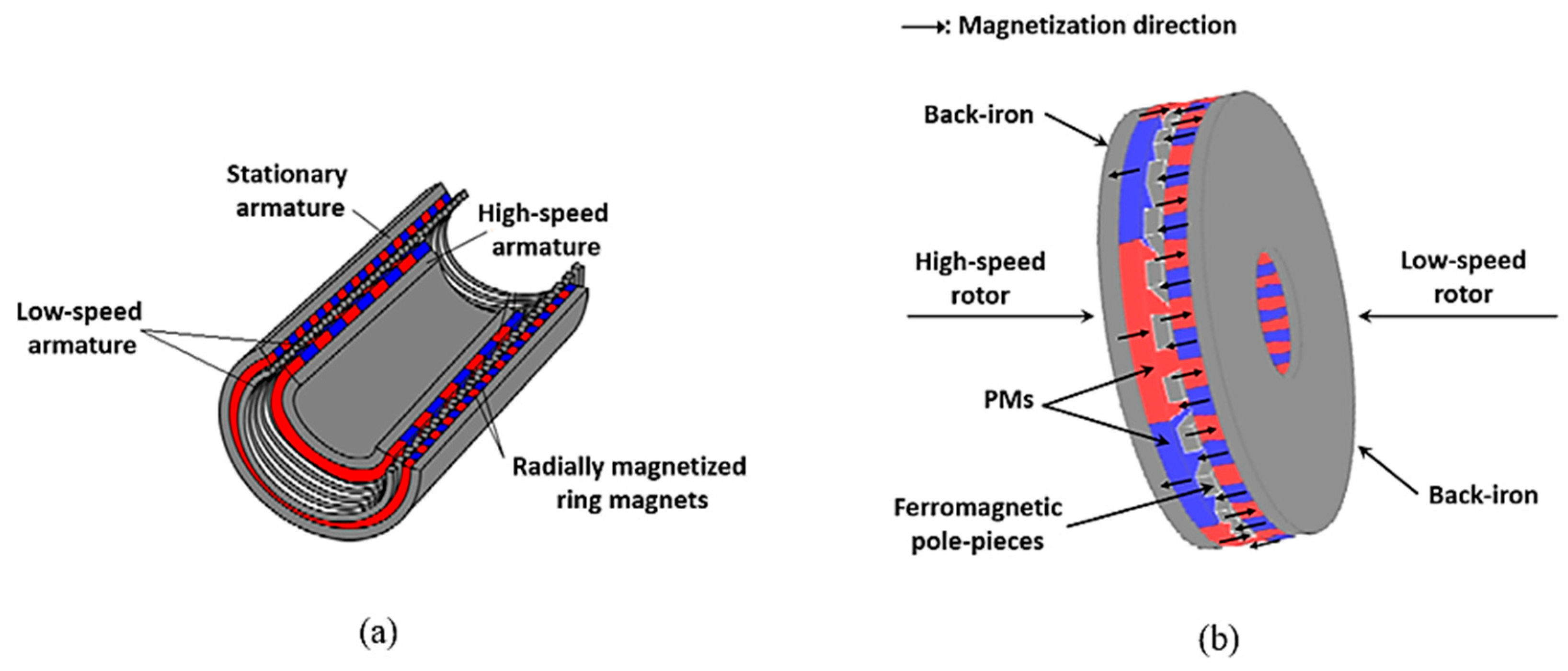
| Axial MG | Compact design. Suitable for applications that require hermetic insulation between the input and output shafts. | Lower torque density compared to coaxial topology due to the impact of axial forces. | Torque density: 70–289.8 kNm/m3 (calculated). | Figure 9b | [85] |
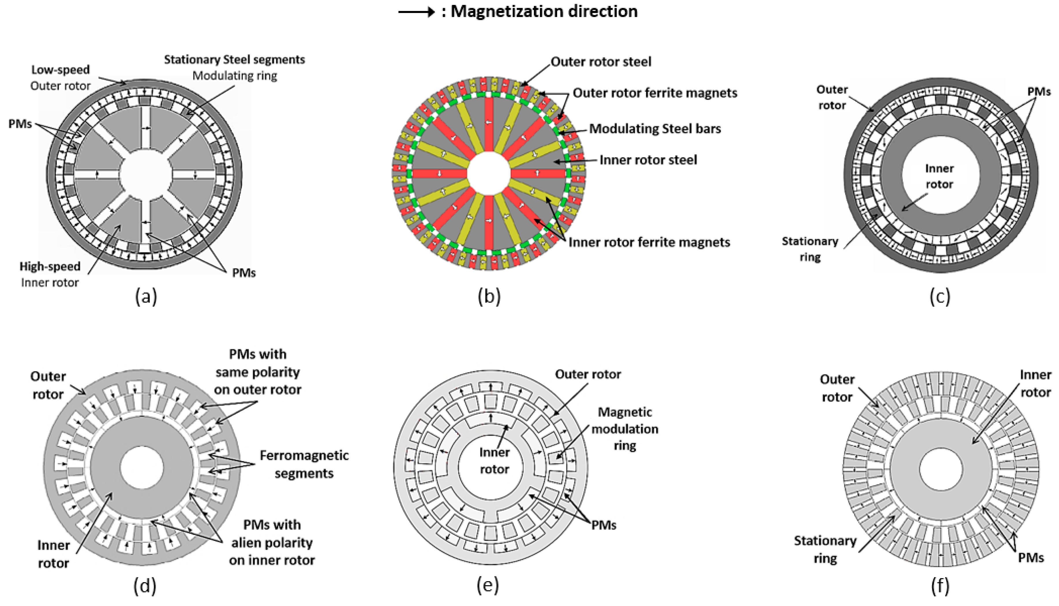
| Spoke-Type Coaxial MG Tangentially Magnetized- Inner Rotor | Flux-concentrating effect and high mechanical reliability. | Large end-effects. Significant reduction of torque capability when compared with the surface-mounted PM configuration. | Torque density: 92 kNm/m3 (calculated). 54.5 kNm/m3 (measured). Torque ripple: 0.79% | Figure 10a | [86] |
| Spoke Ferrite MG | Low-cost (using ferrite magnets). Relatively high torque. | High eddy current losses due to the usage of solid steel in its components. | Torque density: 84.4 kNm/m3 (calculated). | Figure 10b | [87] |
| Surface-Mounted Coaxial MG Halbach Magnetized | 15% higher torque density, 67% reduction in cogging torque and 28% reduction in the total iron losses over a conventional one. | It is difficult to assemble mechanically. Not suitable for practical implementation. | Torque density: 110.7 kNm/m3 (calculated). 108.3 kNm/m3 (measured). | Figure 10c | [77,88,89,90,91,92] |
| Coaxial MG Same-Polarity Magnetized—Outer Rotor | High mechanical integrity and reduced PM material while maintaining torque transmission capability. | Torque density is decreased because of the lower PM consumption at the outer PM rotor. | Torque density: 55.8 kNm/m3 (calculated). 53.3 kNm/m3 (measured). | Figure 10d | [93] |
| Coaxial MG Radially Magnetized, Same-Polarity—Both Rotors | Exhibits superior attributes of lower PM volume but higher transmission capacity. Higher cost effectiveness of ferrite MGs, and slightly larger losses and end-effect. | The actual pull-out torque is slightly lower than the calculated one because the MG end caps are made of steel, a quality which may cause more flux leakage in the axial direction and thus weaken the effective field. | Torque density: 35.4 kNm/m3 (calculated). 23.2 kNm/m3 (measured). | Figure 10e | [94] |
| Surface-mounted Coaxial MG Tangentially Magnetized—Outer Rotor | Better torque density than Spoke-Type Coaxial MG. Flux-focusing effect. | An increase in ripple torque compared to Spoke-Type Coaxial MG. | Torque density: 98.1 kNm/m3 (calculated). 54.5 kNm/m3 (measured). Torque ripple: 1.12% | Figure 10f | [78] |
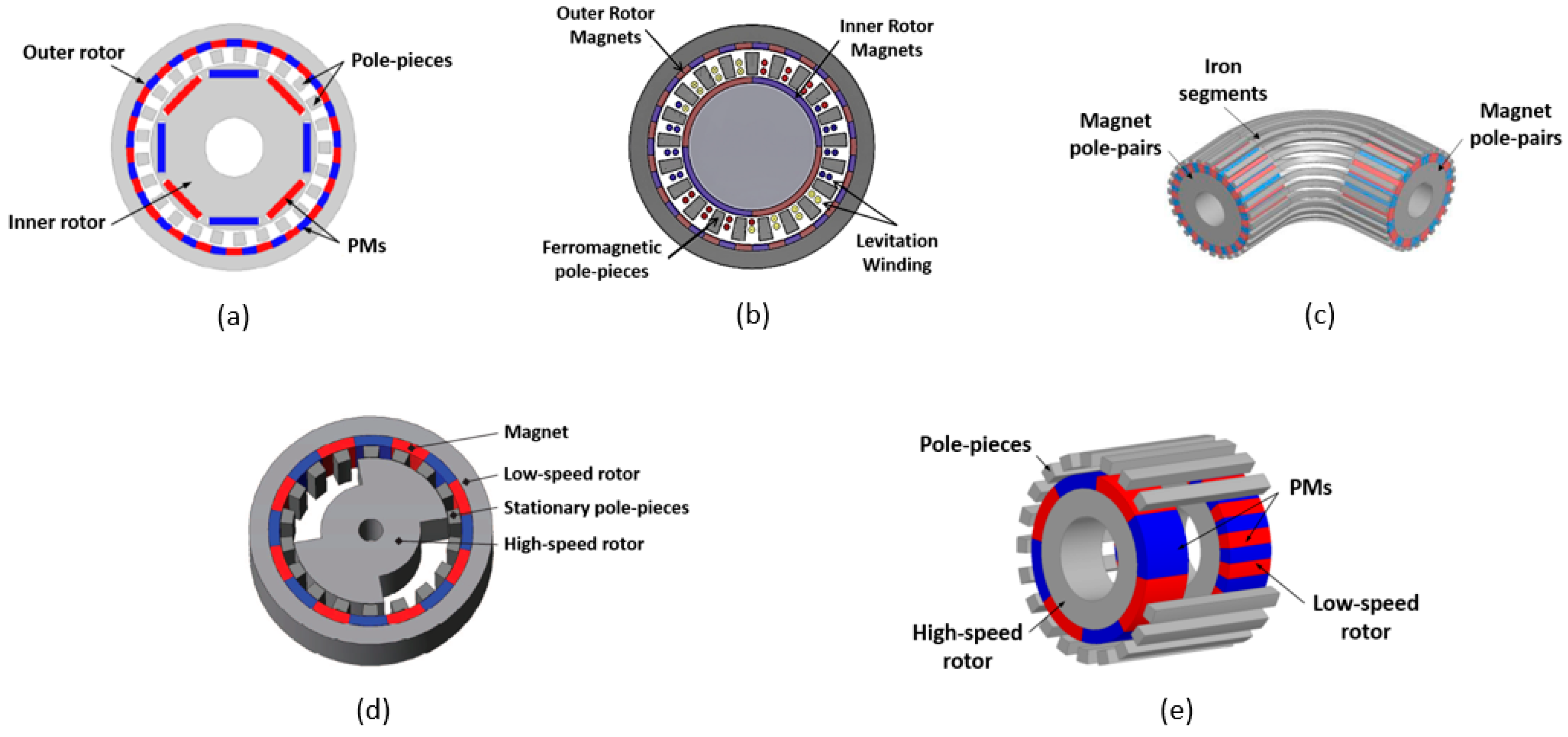
| Surface-Mounted Coaxial MG—Interior PM Rotor | Inner rotor designs with both interior and spoke-type PM configurations are considered. Both configurations significantly reduce torque capability when compared with the surface-mounted PM configuration. | The PMs on the inner rotor are subjected to large centrifugal forces during high-speed operation, | Torque density: 64 kNm/m3 (calculated). 42 kNm/m3 (measured). | Figure 11a | [96,97] |
| Reluctance MG | It can operate in high-speed regions because the structure of a high-speed rotor is very simple and robust. | Torque density and efficiency should be improved with optimization design if it is to be used for high-speed motors. | Torque density: 29.4 kNm/m3 (calculated). | Figure 11d | [100] |
| Transverse Flux MG | Significantly easy manufacturing. | Low torque density. | Torque density: 80.6 kNm/m3 (calculated). | Figure 11e | [102] |
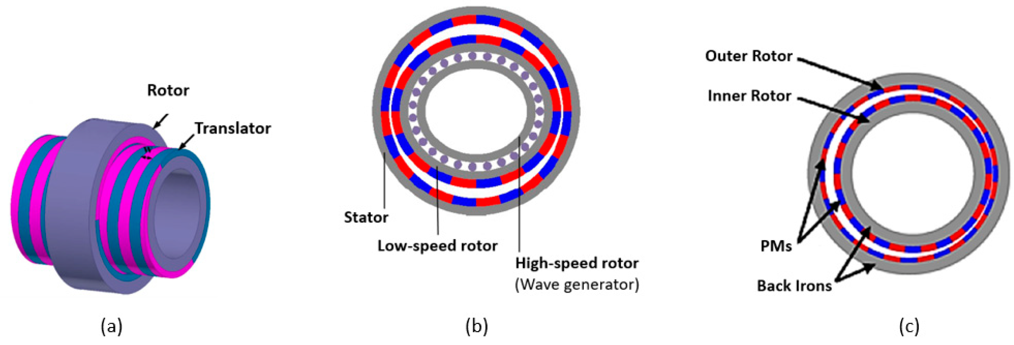
| Trans-Rotatory MG | It can convert high-torque, low-speed linear motion to high-speed, low-torque rotation. Hence, it is highly applicable to wave energy. | Only a portion of the magnetic material is in use during its operation. | Force density: 10 MN/m3 (calculated). | Figure 12a | [108,109,110,111,112,113] |
| Magnetic Harmonic Gear | Suitable for applications that require high gear ratios (greater than 20:1). It exbibits high torque density. | Complicated structure. Its practical implementation is complicated by the need for a flexible PM low-speed rotor. | Torque density: ≈110 kNm/m3 (measured). | Figure 12b | [114,115] |
| Cycloidal MG | It presents extreme torque density and a very high gear ratio. | Complicated construction. | Torque density: 141.9 kNm/m3 (calculated). 106.8 kNm/m3 (measured). | Figure 12c | [116,119] |
Disclaimer/Publisher’s Note: The statements, opinions and data contained in all publications are solely those of the individual author(s) and contributor(s) and not of MDPI and/or the editor(s). MDPI and/or the editor(s) disclaim responsibility for any injury to people or property resulting from any ideas, methods, instructions or products referred to in the content. |
© 2023 by the authors. Licensee MDPI, Basel, Switzerland. This article is an open access article distributed under the terms and conditions of the Creative Commons Attribution (CC BY) license (https://creativecommons.org/licenses/by/4.0/).
Share and Cite
Ruiz-Ponce, G.; Arjona, M.A.; Hernandez, C.; Escarela-Perez, R. A Review of Magnetic Gear Technologies Used in Mechanical Power Transmission. Energies 2023, 16, 1721. https://doi.org/10.3390/en16041721
Ruiz-Ponce G, Arjona MA, Hernandez C, Escarela-Perez R. A Review of Magnetic Gear Technologies Used in Mechanical Power Transmission. Energies. 2023; 16(4):1721. https://doi.org/10.3390/en16041721
Chicago/Turabian StyleRuiz-Ponce, Gerardo, Marco A. Arjona, Concepcion Hernandez, and Rafael Escarela-Perez. 2023. "A Review of Magnetic Gear Technologies Used in Mechanical Power Transmission" Energies 16, no. 4: 1721. https://doi.org/10.3390/en16041721
APA StyleRuiz-Ponce, G., Arjona, M. A., Hernandez, C., & Escarela-Perez, R. (2023). A Review of Magnetic Gear Technologies Used in Mechanical Power Transmission. Energies, 16(4), 1721. https://doi.org/10.3390/en16041721