1. Introduction
The strict requirements on greenhouse emissions and energy efficiency imposed by the maritime authorities [
1,
2] are the basis for the ongoing transition of the current shipboard power systems (SPSs) to more advantageous configurations [
3,
4].
Increased efficiency and environmental sustainability are critical for large passenger ships, such as cruise vessels, where a very high amount of installed power is necessary to supply both electric propulsion systems and hotel services. Such a vessel type is indeed one of the most polluting [
5] and energy-demanding, primarily due to the specific operational profile and the need to accommodate thousands of passengers on board [
6,
7].
Technical solutions with the potential to enable the evolution toward more efficient and sustainable SPSs are manifold. The most promising are the following: use of multiple energy sources on board, including generation units based on fuel cells (FCs), according to a decentralized electricity generation approach; integration of energy storage systems and their coordinated operation with decentralized generators (DGs); massive use of power electronics for shipboard electrical power conversion; use of direct current (DC) electrical distribution systems; use of suitable control techniques and Energy Management Systems (EMSs) to optimize the operation of SPSs [
4]. These solutions contribute to establishing a new electrical paradigm on board, almost in all respects similar to that of terrestrial microgrids (MGs), i.e., the onboard microgrid paradigm.
The decentralized multi-source approach for electrical generation exploits low-carbon or zero-emission energy sources, either in conjunction with conventional diesel-electric generation or not. It is very advantageous since it offers a suitable solution for pursuing high flexibility and reliability of the SPS while complying with the environmental regulatory requirements [
4,
7,
8]. Remarkably, the integration of FC technology in SPSs is envisaged to play an essential role in this perspective, being facilitated by the use of DC distribution systems [
9]. The same applies to battery energy storage systems (BESSs) on board. Indeed, BESSs are broadly recognized as a key technology for making ships safer, more efficient, and less polluting by enabling the implementation of valuable functions such as improvement of the dynamic performance of the electrical plant, peak shaving, and zero-emission operation [
10].
Finally, the need for coordination of multiple power sources/storage systems, the presence of diverse propulsion loads, and the existence of different and variable economic, operational, and environmental requirements make the use of appropriate EMSs crucial for the effective implementation of the onboard MG paradigm.
In the evolution toward more efficient and sustainable SPSs onboard cruise ships, the shipbuilding industry is currently evaluating the realization of modular shipboard MGs to supply hotel loads. These MGs are designed to be self-sufficient systems from an electrical standpoint, being isolated from each other and from the main diesel-electric generators. FCs associated with BESSs are imagined as the only power sources of such local MGs, where electrical power is distributed by hybrid DC/AC distribution systems [
11]. Apart from robust voltage regulations, each islanded MG needs automatic systems that manage the possible operating conditions, i.e., black start, normal, transient, and fault conditions. It should also be considered that an FC is a slow and sensitive device. In fact, if the FC is subject to significant current variations in the absence of an EMS, its life span is substantially shortened.
To the best of the authors’ knowledge, an EMS that is suitably conceived for the above-described electrical architecture is not yet available in the technical literature. Therefore, this work aims at devising an EMS that limits the excursion of the FC’s operating point around the one selected by the MG designer (e.g., as a compromise between power density and maximum efficiency). In this way, the FC’s health is preserved, and the performance expected by the MG designer is granted. This goal is achieved while respecting all the operational constraints of the shipboard MG and ensuring that the battery performs daily charging/discharging cycles.
The proposed EMS takes advantage of the forecasted load demand and consists of two subsystems: (a) a rule-based MG supervisor aimed at managing the possible operating conditions automatically; (b) an EM algorithm, which is executed in normal operating conditions to compute the optimal power reference for the FC.
A comprehensive simulation analysis assessed the validity of the proposed EMS under several operating conditions based on electrical data coming from a real-world cruise vessel.
2. Short Survey of the Related Literature
Several EMSs have been recently proposed in the maritime field, and this section provides a short survey of such contributions from the technical literature. Among them, there are techniques pursuing different goals, focused on different vessel types, and based on several methodologies such as rule-based and optimization-based approaches, power flow optimization, stochastic methods, agent-based strategies, and model predictive-based techniques.
In [
12], the existing literature on rule-based and optimization-based power management systems (PMS) and EMS was presented, and a review of optimization-based EMSs for marine applications was provided. An overview of multi-source shipboard microgrids was given in [
4]. In such a paper, a discussion on several methods for power management (PM) or energy management (EM) was given as well, showing that PMS/EMS can effectively reduce fuel consumption and ship maintenance cost.
The authors of [
8] assessed the effectiveness of a rule-based EMS in accomplishing the goal of maximum fuel economy in an inland diesel-electric hybrid power ship while maintaining the charging profile of the onboard battery in a reasonable range. In [
13], a feasibility analysis was presented for a 47 m zero-emission ferry boat featuring an acceptable energy cost thanks to an EMS.
In [
14], a detailed model of the SPS of a supply vessel was proposed. DC, AC, and hybrid AC/DC power grid architectures were considered. The SPS operations were managed according to a power flow approach to minimize the prime movers’ fuel consumption while satisfying load demand in different operating scenarios.
An agent-based architecture of controllers for stand-alone DC SPSs was proposed in [
15]; it performed voltage regulation and load flow balance control, realizing real-time coordination of all the power converters in the MG.
The authors of [
16] developed an EMS that allows for 20% fuel saving in a roll-on/roll-off vessel fitted with hybrid machinery, energy storage, onshore power supply, and photovoltaic generation. Moreover, in [
17], model predictive control was proposed to improve voltage regulation in advanced SPSs of large-scale vessels. The same objectives were pursued in [
18], where an intelligent single input interval type-2 fuzzy logic controller (iSIT2-FLC) was combined with sliding mode control (SMC). Then, coordinated control among DGs was obtained using a dynamic consensus algorithm (DCA) implemented at the secondary control level.
In [
19], an EMS performing real-time scheduling of the electrical power flows was developed and applied to a suitably modified SPS in a cruise ship to reduce load peaks. Furthermore, an EMS that specifically uses a BESS to cope with load power deviations, fuel consumption, and limitation of the speed transients of the main generation sets was proposed in [
20]. The chosen case study was a yacht equipped with both diesel-electric and renewable generation systems.
Finally, the recent literature proposed different examples of EMSs that exploit hybrid energy storage systems in SPSs to improve the electrical system’s stability and fuel efficiency [
21,
22].
Most literature contributions on EMSs for SPSs are focused on small to medium-tonnage vessels. In such vessels, the prevalent electrical load is the propulsion, and zero-emission SPSs are achievable due to the limited installed power. However, in the case of cruise vessels, it is not yet possible to imagine the onboard installation of FCs and BESSs that are large enough to meet the whole ship’s energy demand (i.e., for propulsion and hotel services). Moreover, hotel loads represent a significant percentage of the installed power, and the shipbuilding industry is currently considering for such vessels new decentralized electrical architectures based on the MG concept. Therefore, the development of EMSs devoted to shipboard MGs supplying hotel services on cruise ships, like the EMS proposed in this paper, deserves specific attention and dedicated efforts.
4. Energy Management System for the Shipboard MG
The task of regulating the MG voltage can be accomplished only by the control systems of the power electronic converters that interface the power sources with the DC bus. Usually, droop control is adopted, aiming to respect a predefined power-sharing ratio among the sources. However, this control architecture does not leave any degree of freedom to pursue other goals in addition to voltage regulation. If more advanced management of the MG is desired, some of the power sources must be current-controlled, and an EMS must be used to compute their optimal current (or power) reference.
As previously stated, the goal set for the EMS under study is to limit the excursion of the FC’s operating point around the optimal point chosen by the MG designer. Consequently, the following requirements were formulated:
Ensure power balance by making the battery compensate for load power fluctuations around the average value that is supplied by the FC;
Ensure regular battery charging/discharging cycles;
Respect FC and battery power limits;
Respect battery state of charge (SOC) limits.
It is worth noting that it is not possible to meet all the requirements simultaneously without an EMS, i.e., by leveraging only the control systems of the power converters. In fact, the lack of a planning operation results in a greedy approach. For example, if the control system considers a fixed average power (e.g., 50% of the rated MG load) while pursuing the first requirement, the SOC boundaries could be reached prematurely. In this case, more than one daily charging/discharging cycle could be needed, thus not fulfilling the second requirement and leading to decreased battery life span. Therefore, there was the need for an EMS that considers the forecasted load demand, plans the SOC profile for the next 24 h, and periodically updates the power reference for the FC. Furthermore, an additional requirement was considered:
- 5.
Properly manage the MG also when it is not in normal operating conditions.
For example, it must be possible to feed the MG using only one power source, to allow the black start of the MG using the battery while the FC warms up, and to manage faults and possible incorrect power references decided by the EMS that can lead to SOC limit violations or power unbalance. This requirement is very important because each MG in the modified SPS is a weak grid. Therefore, besides the EM algorithm, the EMS must also encompass a suitable rule-based MG supervisor to manage the MG when it is not in normal operating conditions.
Based on all the above requirements, it was decided to share the enforcement of the requirements among the control system and the two components of the EMS, i.e., the EM algorithm and the MG supervisor. In particular, the control system of each power converter is able to control the corresponding power source either in voltage droop mode (with the aim of regulating the MG voltage) or in current mode (to impose the optimal power reference computed by the EMS); thus, if one power source is controlled in current mode and the other in voltage droop mode, Requirement 1 is enforced. Moreover, the control systems are in charge of enforcing the FC and battery power limits as per Requirement 3.
The MG supervisor constantly evaluates the operating conditions of the MG. In normal operating conditions, it merely propagates to the control system the optimal power reference computed by the EM algorithm. During the other operating conditions, it takes over and alters the power reference computed by the EM algorithm to enforce Requirements 4 and 5.
Finally, the EM algorithm is activated only in normal operating conditions. It performs optimal planning based on the forecasted load demand to compute the optimal FC power reference, thus pursuing the chosen goal while enforcing Requirements 2, 3, and 4. As will be shown in the following subsections, there could be unlikely events in which the EM algorithm chooses a power reference that pursues the goal and enforces Requirements 2 and 3 but does not satisfy Requirement 4. In such cases, the MG supervisor would detect that the MG is not in normal operating conditions, take over, and enforce Requirement 4.
In the following, first, the control system architecture is explained; then, the two components of the proposed EMS, namely the EM algorithm and the MG supervisor, are described in depth.
4.1. Control System Architecture
Only two power sources are present in each MG of the considered case study; thus, in normal operating conditions, one source must be current-controlled and the other droop-controlled. The task of regulating the MG voltage in a droop fashion was assigned to the battery because it exhibits higher short-circuit power and dynamic performance than the FC. Instead, the FC can be operated either in current mode or in droop mode. The FC is operated as a current generator during normal conditions, providing the average load power. In such a control mode, the set point for the FC (i.e., the optimal current reference) is computed dynamically by the EM algorithm based on the forecasted load profile for the next 24 h divided by the MG voltage. The load power fluctuations around the average power are compensated by the droop-controlled battery, thus satisfying Requirement 1.
On the other hand, the FC is operated in droop mode during the other foreseen operating conditions (i.e., black start, temporary conditions, and fault conditions). Thus, it can automatically share the load with the battery without the need for a current reference decided by the EM algorithm.
Table 3 shows an overview of the possible control modes of the FC and battery converters in each shipboard MG.
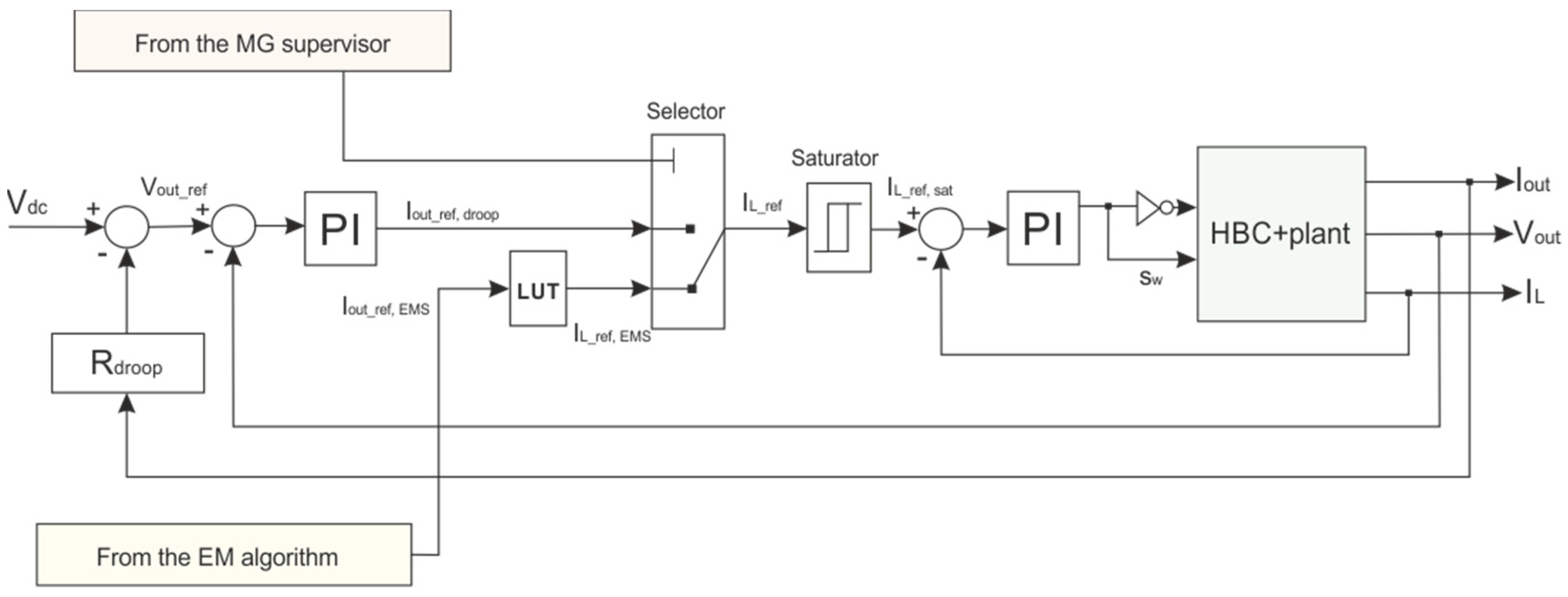
It is worth highlighting the general features of the control system used for the HBC power converters that interface the two power sources with the DC bus. As shown in
Figure 3, a current loop is needed in both droop-mode and current-mode operation to regulate the input current of the HBC, which is the inductor current
IL. This way, the inductor current reference
IL_ref can be routed through a saturator to allow respecting the power limits of the FC and the battery as per Requirement 3. Such a reference can be generated in two ways. In the case of current-mode control, the EM algorithm decides the optimal output current reference
Iout_ref,EMS, which is then converted to an optimal inductor current reference
IL_ref,EMS using a look-up table. On the other hand, in the case of droop control, the inductor current reference
IL_ref,droop is directly generated by the control loop that regulates the output voltage
Vout. Finally, the reference
Vout_ref for the voltage loop is computed through a third control loop that implements the chosen droop characteristic given the rated DC MG voltage
Vdc and the droop resistance
Rdroop. Overall, the controller must limit voltage deviations under ±10% during transients and under ±5% at steady state.
Since the MG voltage regulation is delegated to the battery during normal operating conditions, the intervention of the current saturator of the BESS converter could compromise the power balance during exceptionally bad transients. Thus, the saturator intervention generates a logic signal that is processed by the MG supervisor to restore power balance (see
Section 4.3).
Finally, as for the battery SOC limits, they are related to physical phenomena characterized by slower dynamics; thus, their enforcement, as per Requirement 4, is delegated to the EM algorithm and the MG supervisor rather than the control system. It is worth noting that other control system architectures could in principle be used as well; nevertheless, the choice of control architectures is not relevant as long as the controlled variables are the same and an external output current reference can be supplied to the control system by the EM algorithm.
4.2. EM Algorithm
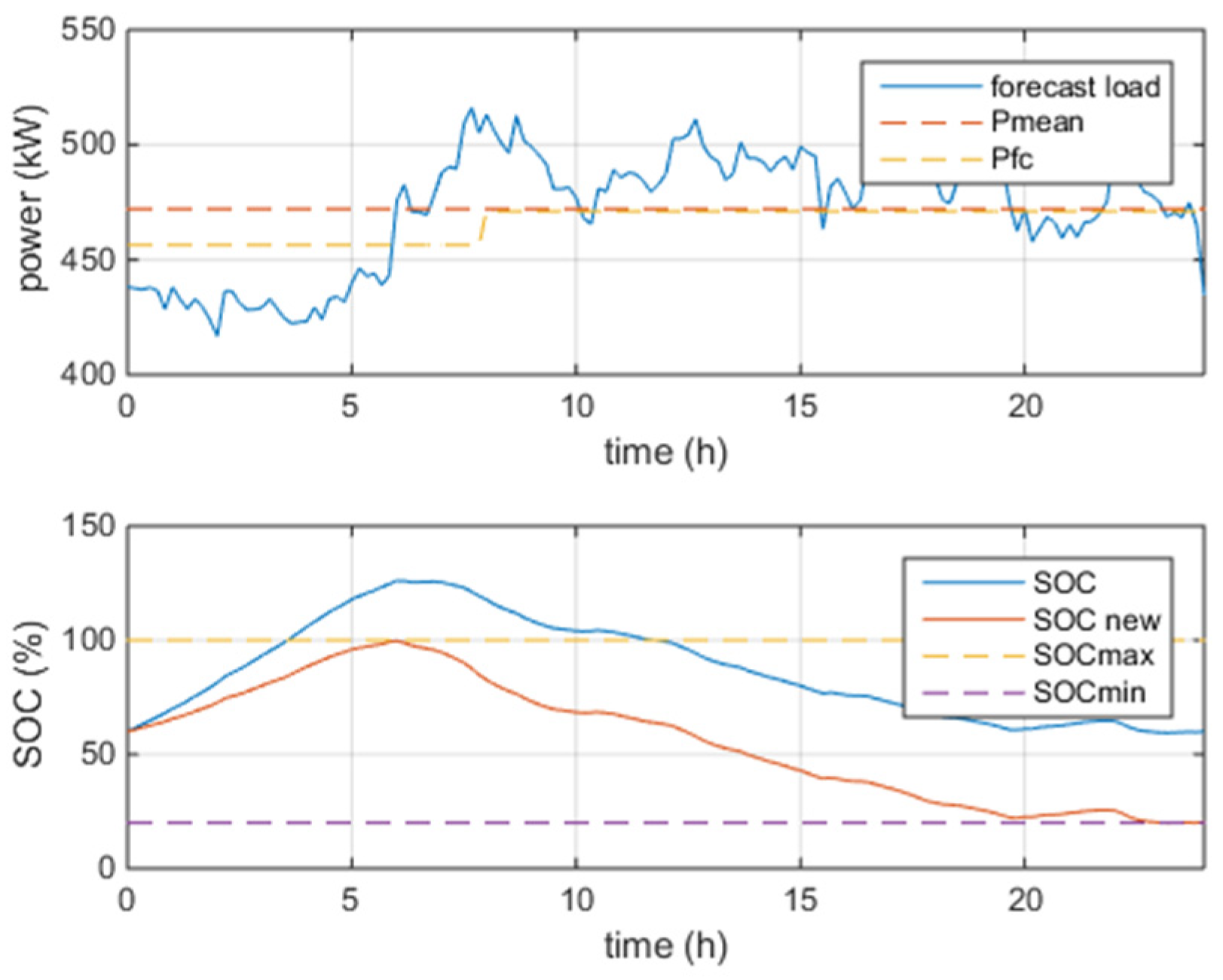
As stated before, the EM algorithm is executed in normal operating conditions to compute optimal power references that allow the FC to operate as much as possible at constant power near the operating point decided by the MG designer while respecting Requirements 2, 3, and 4. The simplest way to achieve this goal is to consider the forecasted power demand for the next 24 h, extract its average value, and provide it as a reference to the FC converter. However, this approach may not ensure compliance with the battery’s maximum and minimum SOC limits. For example, SOC limits could be violated when extended charging (discharging) periods are required starting from a very high (low) initial SOC. Furthermore, even considering an initial SOC of 100% (or ) at the beginning of the day, the energy to be exchanged in the discharging (or charging) phase may exceed the usable capacity of the battery, i.e., . For the above reason, a more sophisticated rule-based EM algorithm was devised to ensure compliance with SOC limits by reshaping the daily SOC profile when needed. Since the load demand profile is cyclical, it is possible to assume midnight as the daily cycle’s starting time and consider 8 h/16 h as the duration of the night/day periods.
The reshaping criterion used by the EM algorithm can be explained by referring to a sample day of the recorded dataset. The forecasted load demand and its average value
Pmean are shown in the first graph of
Figure 4 in blue and orange, respectively. By considering these curves, the profiles of the power and energy delivered by the battery can be computed. Then, it is possible to determine the
SOC evolution in the following 24 h based on the initial
SOC at midnight, e.g.,
SOC0 = 60%. Such a trend is shown in blue in the second graph of
Figure 4, together with the lower (purple) and upper (yellow)
SOC limits.
Since violations of the SOC limits occur, the EM algorithm must reshape the SOC profile by applying a corrective contribution ΔP to the average power Pmean to comply with such limits. However, on this specific day, it is impossible to compute a value of ΔP that allows respecting both SOC limits due to the particular trend of the forecasted load demand. On days like this, the EM algorithm then performs the reshaping independently for the night and day intervals, computing two corrective contributions and two different power references for the FC (i.e., one for the night and one for the day). Initially, ΔPnight is computed to make the SOC profile tangent to the upper SOC limit during night hours. Then, the expected SOC value at the transition between night and day is determined, and ΔPday is calculated to make the SOC profile tangent to the lower SOC limit during daytime.
The new expected
SOC profile (
SOCnew) is shown in orange in the second graph of
Figure 4. The power reference profile for the FC (i.e., the step variation from
Pmean + Δ
Pnight to
Pmean + Δ
Pday) is shown in yellow in the first graph of
Figure 4. It is worth noting that no reshaping would have been needed on the same day if the initial
SOC were lower, e.g.,
SOC0 = 20%.
Besides the
SOC limits, the nominal FC power and the battery’s maximum charging/discharging power must also be respected as per Requirement 3. Considering the FC and battery sizing, such constraints will usually be respected with a large margin. However, under exceptionally high forecasting errors, it might not be possible to determine the corrections Δ
Pnight and Δ
Pday in compliance with the constraints on
SOC and powers. However, this is not a problem because they will be enforced in any case by the MG supervisor. In such a case, the EM algorithm must respect the more critical
SOC constraint, i.e., the lower
SOC limit, in addition to the current constraints of the two sources. In fact, as will be discussed in
Section 4.3, violating the lower
SOC constraint could lead to a fault condition, whereas the violation of the upper
SOC constraint would be less critical.
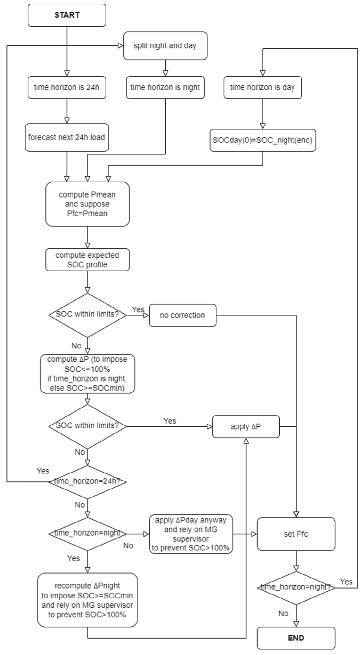
The whole rule-based EM algorithm is summarized through the flowchart shown in
Figure 5.
4.3. MG Supervisor
The rule-based MG supervisor constantly evaluates the user input and the overall state of the DC MG (i.e., the MG voltage and the operating conditions of the two power sources). This way, it detects the four foreseen operating conditions (i.e., black start, normal operating conditions, temporary conditions, and fault conditions). Then, it sets the correct control mode for each power converter and activates the EM algorithm only during normal operating conditions.
Even in the presence of incorrect current references computed by the EM algorithm (due to exceptionally high forecasting errors or the impossibility of respecting both SOC limits), the MG supervisor is able to enforce maximum and minimum SOC constraints ensuring power balance. Furthermore, if requested by the user, it allows powering the local MG using only one power source or forcing the emergency black start using a battery with an initial SOC lower than 15% and an already warm FC operating in droop mode.
It is worth highlighting that the SOC management performed by the MG supervisor considers more thresholds compared to the EM algorithm. In fact, the EM algorithm plans to keep the SOC between 20% and 100%, as recommended by the battery manufacturer for normal operating conditions. However, the SOC can also decrease below 20% during transient operation, although it must not fall below 5% to avoid significant battery degradation. In addition, the execution of charge and discharge micro-cycles close to SOC = 100% should also be avoided. For example, recharging can be prevented when the SOC stays in the range [95%, 100%].
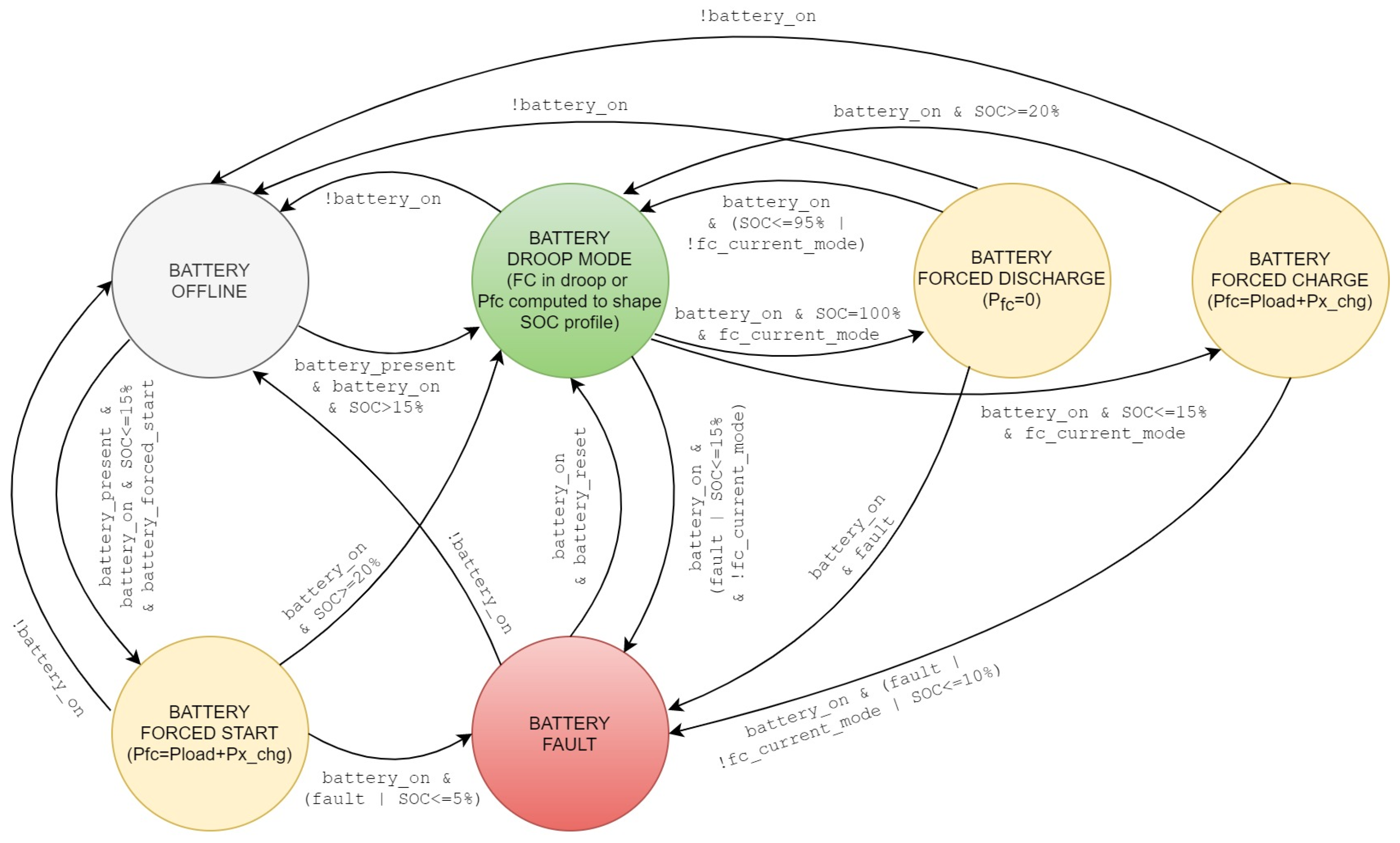
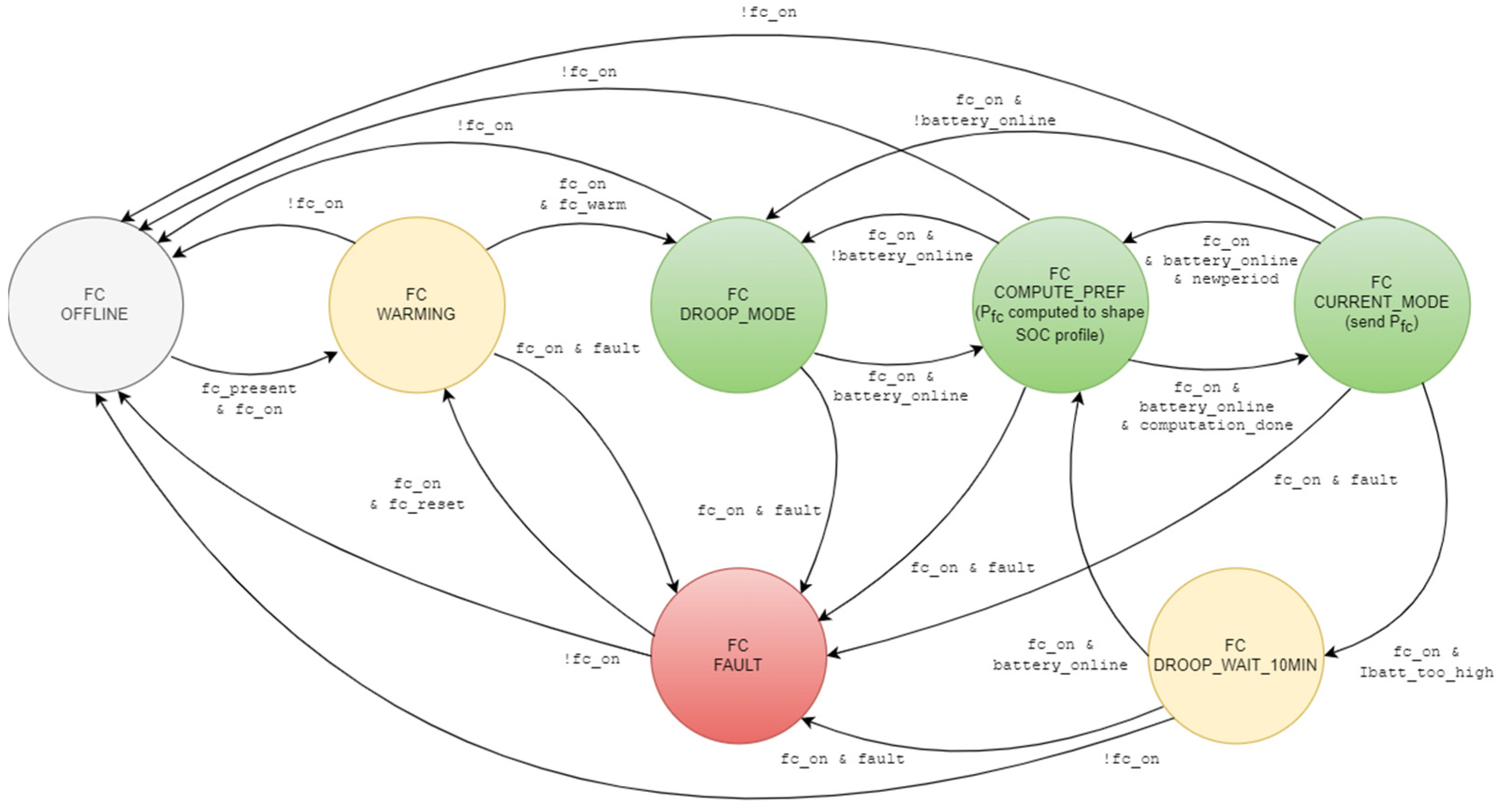
The MG supervisor was implemented using a couple of Finite State Machines (FSMs), i.e., one for the FC and one for the battery. The operation of these FSMs in the four foreseen operating conditions is described by the state diagrams shown in
Figure 6 and
Figure 7. In these diagrams, the states are colored according to the following criterion: gray = device not active or not present; green = operating condition that can last indefinitely; yellow = temporary operating condition; red = fault condition.
The battery FSM includes the six states shown in
Figure 6 and generates the
battery_online signal, which is set high when the battery is not offline or in fault conditions. The FC FSM includes the seven states shown in
Figure 7 and generates the
fc_current_mode signal, which is set high when the FC FSM is in the FC_CURRENT_MODE state.
The state transitions of the battery FSM are determined by the signal fc_current_mode, a configuration parameter (battery_present), and the input signals generated by the user and the battery control system. In particular, the user-generated signals are battery_on, battery_forced_start, and battery_reset; the signals generated by the battery’s control system are SOC, I_batt_too_high, and fault.
On the other hand, the state transitions of the FC FSM are triggered by the signal battery_online, a configuration parameter (fc_present), the timing signals computation_done and newperiod (generated with a periodicity corresponding to the time interval used by the EM algorithm), and the input signals generated by the user and the FC control system. In particular, the user-generated signals are fc_on and fc_reset, whereas the signals generated by the FC’s control system are fc_warm and fault.
All the foreseen operating conditions will be described in the following by referring to the state diagrams of
Figure 6 and
Figure 7, except for fault conditions, which are pretty intuitive.
4.3.1. Black Start
The black start is performed by exploiting the battery operated in droop mode since the FC requires prolonged startup times and is highly sensitive to current transients. First, only the essential loads are supplied by the battery. Once the MG voltage reaches its nominal value and the FC reaches its rated operating temperature, the FC is connected to the MG and operated in droop mode. Then, non-essential loads are connected to the MG, and the entire MG load can be jointly supplied by the battery and the FC. Thus, the startup sequence of the FC is completed, and the related power converter is ready to be switched to current-mode control, falling into the case of normal operation.
4.3.2. Normal Operation
At the end of the black start procedure, both the battery and FC are operated in droop mode and supply the load proportionally to the respective droop coefficients. However, FC_DROOP_MODE does not represent the normal operating state of the FC because: (1) it does not allow the FC to recharge the battery; (2) it does not allow the optimal FC operating point chosen by the EM algorithm to be imposed.
Therefore, the FC state alternates between FC_COMPUTE_PREF and FC_CURRENT_MODE during normal operating conditions based on the newperiod and computation_done signals. In FC_COMPUTE_PREF, the EM algorithm computes the optimal FC power reference. At the end of the computation, the FC converter is set to current mode and receives such a power reference. The battery always stays in BATTERY_DROOP_MODE; thus, it regulates the MG voltage and naturally provides the additional power needed to preserve power balance (positive during discharging, negative during recharging).
4.3.3. Temporary Operation Conditions of the FC
If the EM strategy does not correctly choose the power reference for the FC (e.g., due to an exceptionally high forecasting error) and the battery current is saturated (signal Ibatt_too_high active), the power balance might not be satisfied. In this case, the MG voltage would rapidly increase or decrease, possibly exceeding the allowed range. However, when the FC FSM receives the signal Ibatt_too_high, it immediately forces the transition to FC_DROOP_WAIT_10MIN. In such a state, the FC converter is again set in droop mode to restore power balance and waits for 10 min to allow the perturbation to cease. After this time, the system returns to FC_COMPUTE_PREF, and the EM algorithm updates the current reference for the FC converter again.
It should be noted that the transition to FC_COMPUTE_PREF does not alter the control mode of the FC converter, which is changed only in FC_DROOP_MODE and FC_CURRENT_MODE.
The saturator of the FC control system is never triggered when the FC is in current mode because the EM algorithm always provides current references below the maximum FC current. Instead, the saturator could be potentially triggered when the FC is in droop mode, although this is a remote possibility considering the FC and battery sizing. In such a case, the current supplied by the battery would increase to restore the power balance. Then, if the battery saturator is also triggered, the grid voltage would rapidly drop outside the allowed range, the protection devices would de-energize the grid, and the black start procedure should be repeated.
4.3.4. Temporary Operating Conditions of the Battery
As a result of exceptionally high forecasting errors, it could theoretically happen that the EM algorithm decides a current reference for the FC such that the battery would be charged over 100%, not respecting the upper SOC limit. This anomalous condition is prevented by the transition to BATTERY_FORCED_DISCHARGE, where the power reference decided by the EM algorithm is bypassed, imposing a null reference. Thus, the battery begins discharging, avoiding damage. The battery FSM returns to BATTERY_DROOP_MODE in two cases: when its SOC falls below 95% and the FC is in FC_CURRENT_MODE or when the FC goes into FC_DROOP_MODE (where it cannot charge the battery). The opposite situation arises when battery SOC falls below 15%: the battery is charged at maximum power in BATTERY_FORCED_CHARGE, bypassing the power reference decided by the EM algorithm. If the SOC goes above 20%, the battery FSM returns to BATTERY_DROOP_MODE. If the SOC keeps decreasing and falls below 10% due to some anomaly or if the FC unexpectedly exits from FC_CURRENT_MODE, the battery transitions to BATTERY_FAULT and is disconnected from the grid. In this scenario, the MG is powered by the FC alone, if available.
4.3.5. Forced Start
A state called BATTERY_FORCED_START was also introduced to exceptionally allow the black start using a battery with an initial SOC lower than 15% and an already warm FC operating in droop mode. The limit of 15% of SOC was chosen because it is slightly lower than the recommended 20% limit, but the SOC is supposed to increase rapidly thanks to the contribution of the FC. The power reference decided by the EM algorithm is bypassed with a value that allows charging the battery at maximum power. If the SOC increases beyond 20%, the battery is no longer considered at risk of damage; thus, its FSM transitions into BATTERY_DROOP_MODE, and normal operation resumes. On the other hand, if it decreases and falls under 5%, a fault condition is triggered.
5. Results
The proposed EMS was implemented and tested in simulation using load demand data recorded over the cruise ship’s itinerary. To this aim, it was necessary to implement in C++ language the simulator engine, the EMS, and the subsystems that interface the EMS with the load forecasting module and the hardware (i.e., the FC and BESS power converters). Since the developed EMS was agnostic to the actual implementation of external systems, it was possible to emulate the power converters and the load forecasting module. Thus, in the present study, a Plant Emulator was developed in Python to emulate the static behavior of the MG comprising the two generators, the related power converters, and the aggregated load. Discrete-time linear models were used in the simulator. As for the forecasting module, the most suitable choice for such an application is to resort to artificial neural networks (ANNs) [
25,
26]. However, the available load demand recordings only spanned a short period and were not sufficient to train the ANN properly. Thus, the forecasted load profiles were simulated by applying a Gaussian error to the available experimental load profiles.
The main cycle of the simulation includes the following steps:
Read the electrical measurements from the Plant Emulator;
Assess the state transitions based on the measurements to obtain the set of control signals;
Execute the EM algorithm if the state is FC_COMPUTE_PREF to obtain the current reference for the FC;
Transmit the set of control signals and the current reference to the Plant Emulator and request to update the emulated electrical quantities after a sampling period.
The EMS performance was validated in three scenarios. In Scenario 1, the black start of one of the accommodation MGs was performed. In Scenarios 2 and 3, the operation of the EMS was simulated over a multi-day period for the same accommodation MG considered in Scenario 1 and for the galley MG, respectively.
It is worth specifying that the droop coefficients of the battery and the FC are equal; thus, the two generators contribute equally to supplying the loads when the FC is droop-controlled. In particular, the droop coefficients were chosen to impose a steady-state voltage reduction of 5% when the maximum load was supplied by each power source alone.
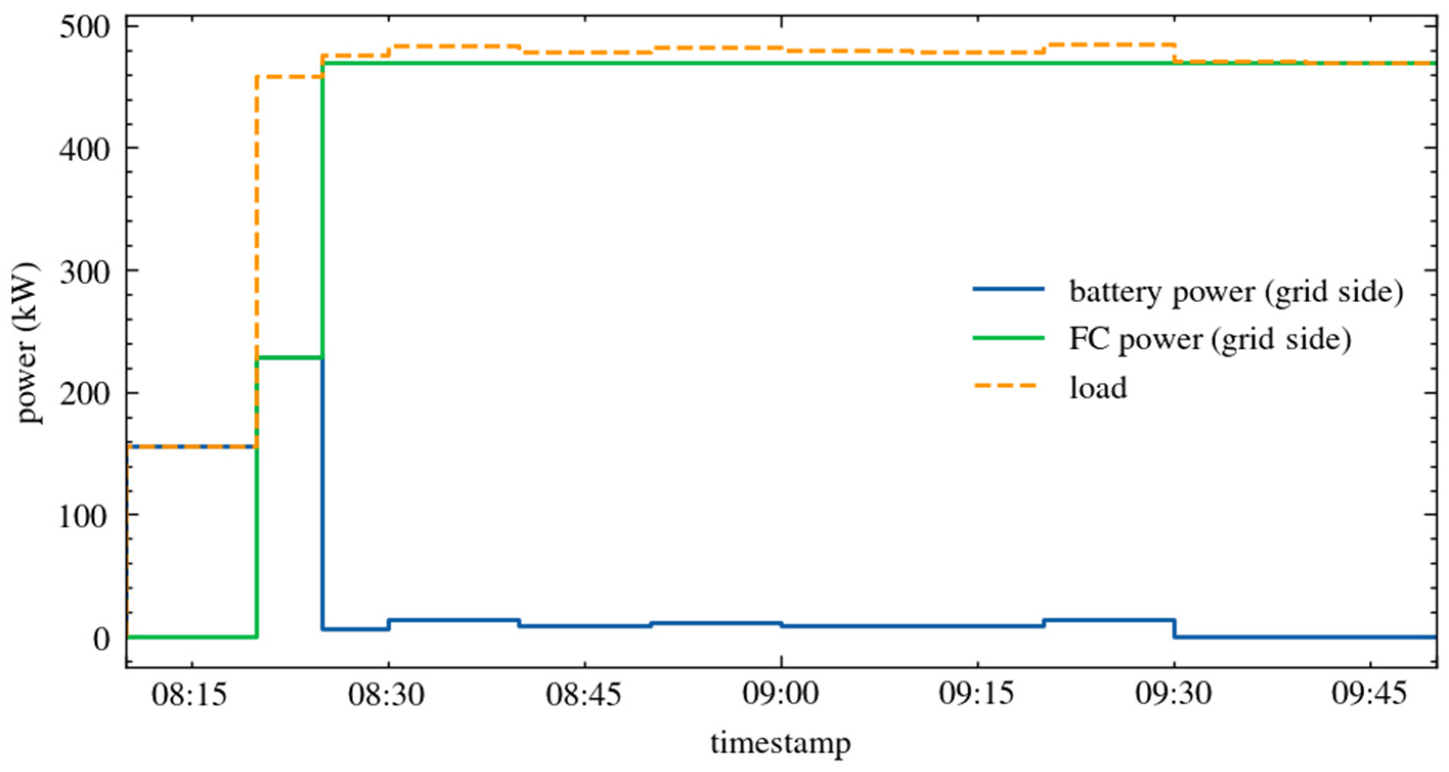
5.1. Scenario 1: Black Start
In this first scenario, the simulation was started with the sources disconnected and powered off. The initial battery
SOC was 50%. Then, the MG was energized with the correct sequence imposed by the FSMs.
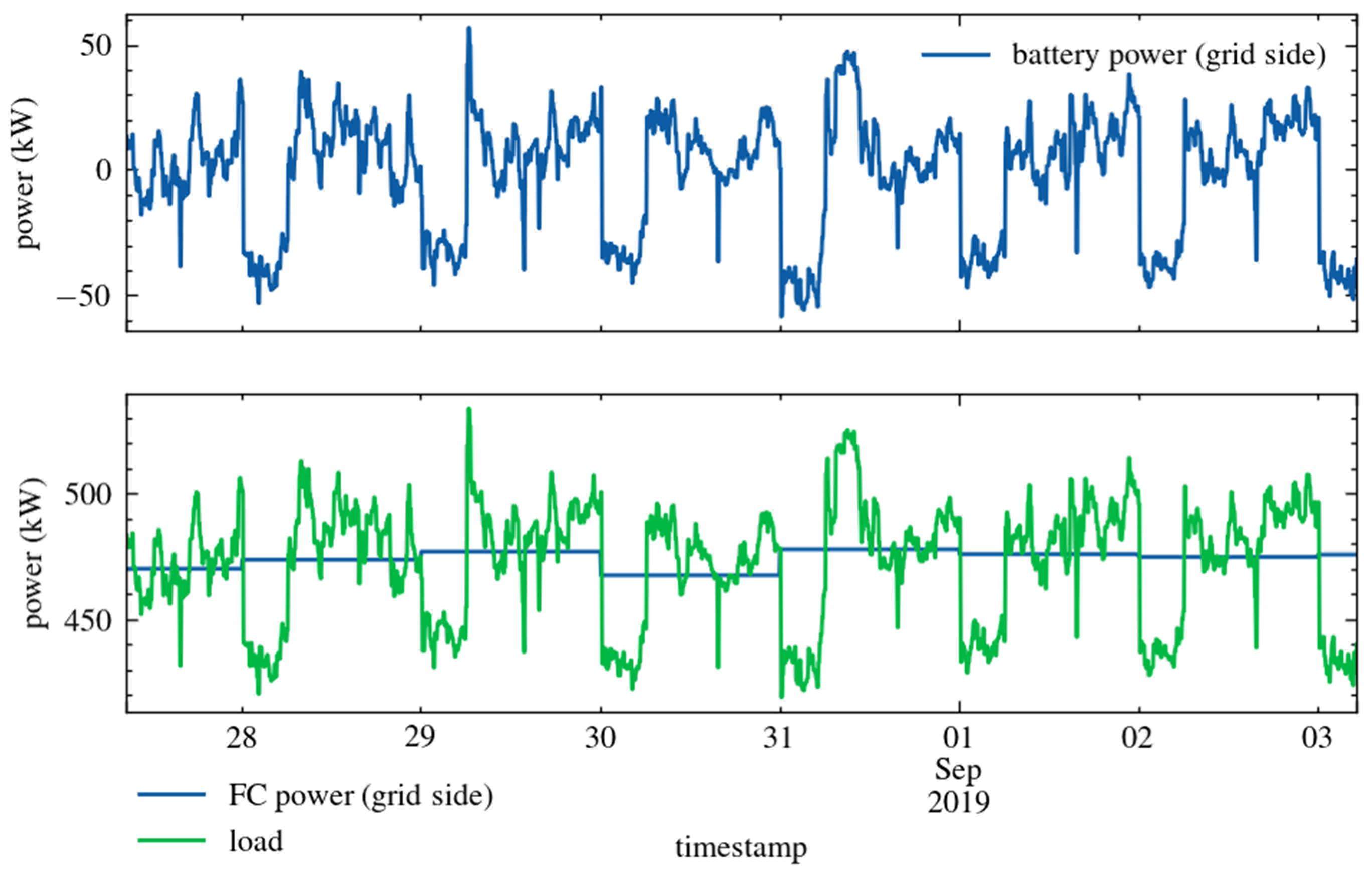
Figure 8 shows the obtained grid-side power profiles, namely, the load power demand, the FC grid-side power, and the battery grid-side power.
At first, when the battery_on and fc_on signals were sent, the battery FSM transitioned to BATTERY_DROOP_MODE and the FC FSM to FC_WARMING. Thus, the supervisor turned on the battery and connected it to the MG to supply the essential loads. At the same time, the supervisor powered on the FC to start the warmup process. Then, when the FC warmup was completed, non-essential loads were also connected, and the FC supplied half the demanded power operating in droop mode.
At the next time step, the FC FSM transitioned to FC_COMPUTE_PREF. The EM algorithm only considered the daytime interval at its first execution; it calculated the mean value of the forecasted load power demand and applied the reshaping, thus selecting the power reference value for the rest of the day.
Once the EM algorithm execution was completed, the FC FSM transitioned to FC_CURRENT_MODE and set the FC converter to current-control mode, providing the calculated power reference. This transition completed the black start procedure and entered the normal MG operation.
It can be observed that once the FC was in FC_CURRENT_MODE, it supplied the load with the power calculated by the EM algorithm, whereas the battery (controlled in droop mode) provided the remaining load power. The droop control of the battery resulted in MG voltage variations that are much smaller than 5% of the nominal voltage (1 kV DC), guaranteeing stable operation.
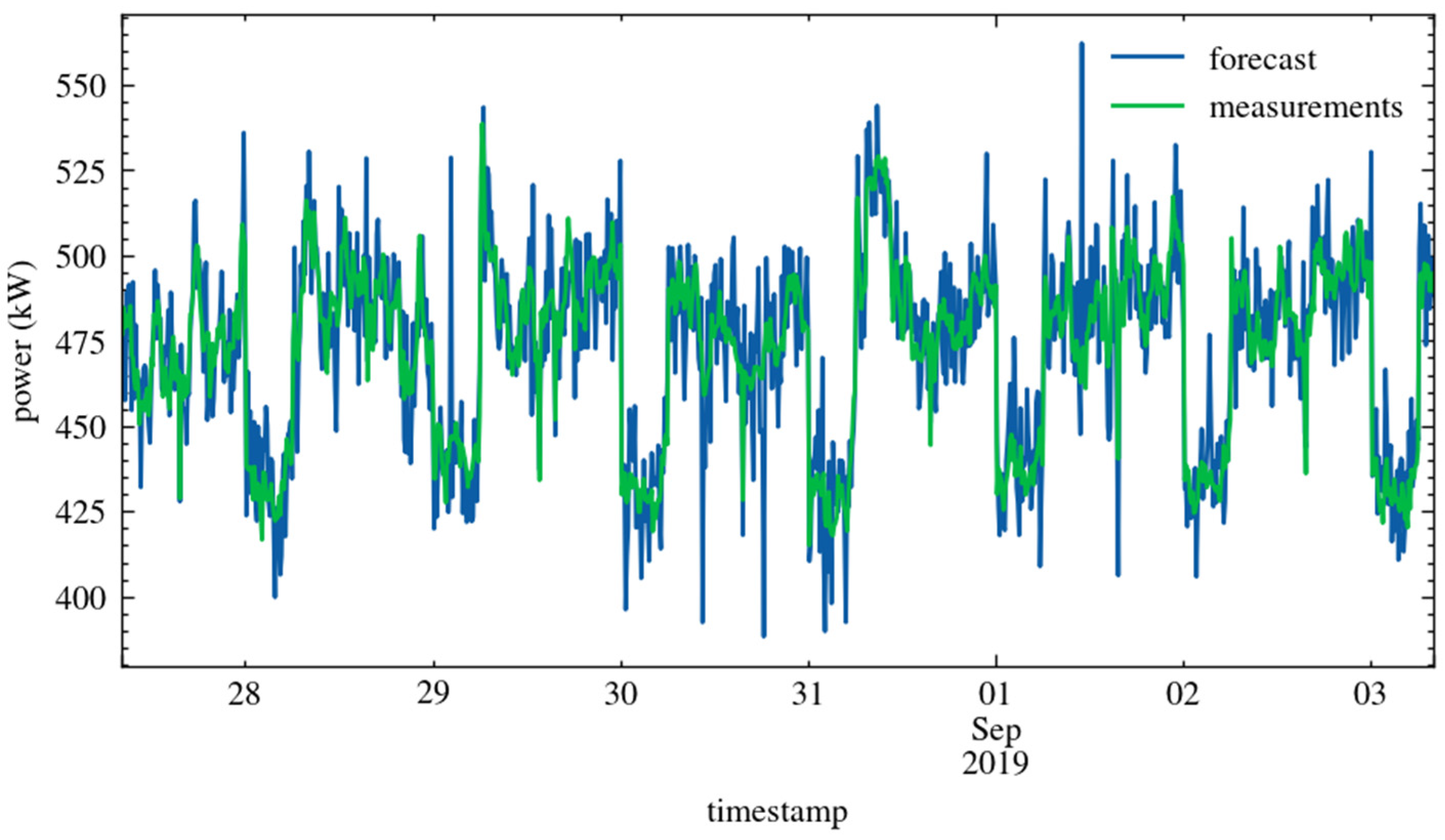
5.2. Scenario 2: EMS Operation in the Accommodation MG
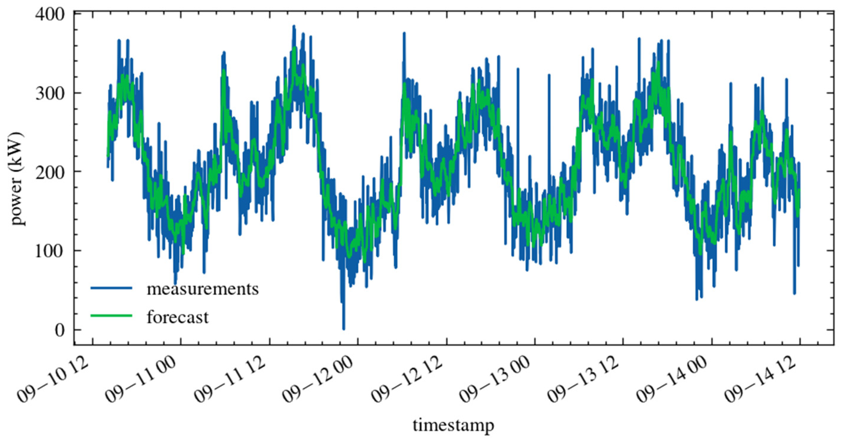
This scenario was simulated assuming that the grid energization procedure was completed. Thus, the FSM of the battery started in BATTERY_DROOP_MODE, and the FSM of the FC started in FC_CURRENT_MODE. The measured load demand profile and the corresponding forecasted profile, plotted over a multi-day period, are depicted in
Figure 9.
The MG operation was simulated over a 7-day period.
Figure 10 shows the obtained grid-side power profiles of the sources and load. The FC supplied constant power until midnight of the first day. Then, for each new day, the FC FSM received the
newperiod signal, and the recalculation of the power reference value of the FC was triggered. It can be observed that, in the considered period, the EM algorithm found no need to apply the reshaping procedure for day and night independently. Therefore, a single power reference value was chosen for each simulated day.
Figure 10 also shows the behavior of the battery that took charge of the load demand fluctuations around the power supplied by the FC, also compensating for forecasting errors. Again, the voltage variations were well below 5%, guaranteeing stable operation.
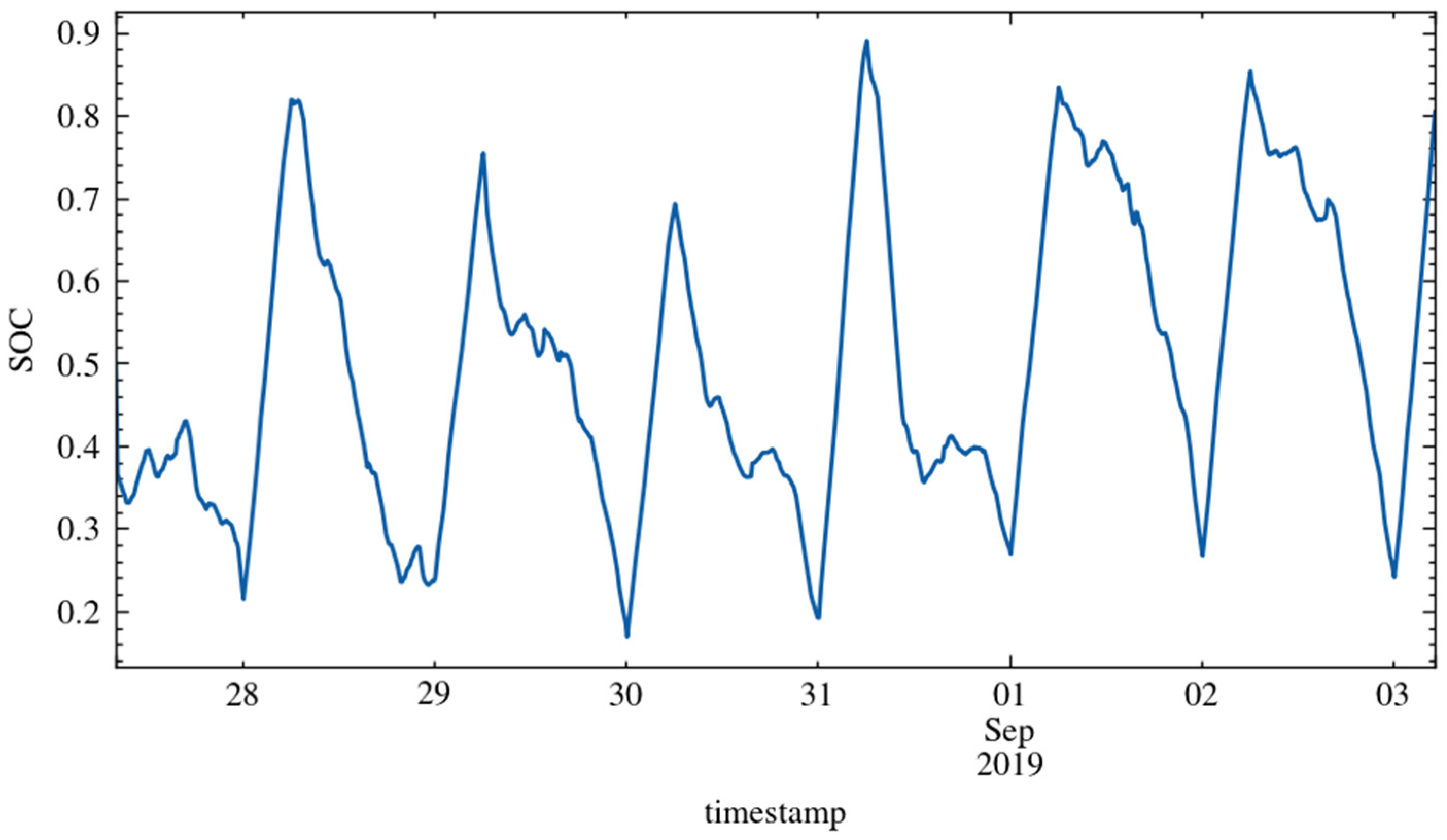
The obtained battery
SOC profile is plotted in
Figure 11 and shows that the
SOC constraints were satisfied. Moreover, it is worth observing the almost complete cycles of charge and discharge that repeat daily. These confirm the correct operation of the EM algorithm and the correct sizing of the battery.
Finally, it should be noted that there were no forecasting errors so large to make battery SOC decrease below the 15% threshold (that would have determined the transition of the battery FSM to BATTERY_FORCED_CHARGE) or the activation of the Ibatt_too_high signal (that would have determined the transition of the FC FSM to FC_DROOP_WAIT_10_MIN).
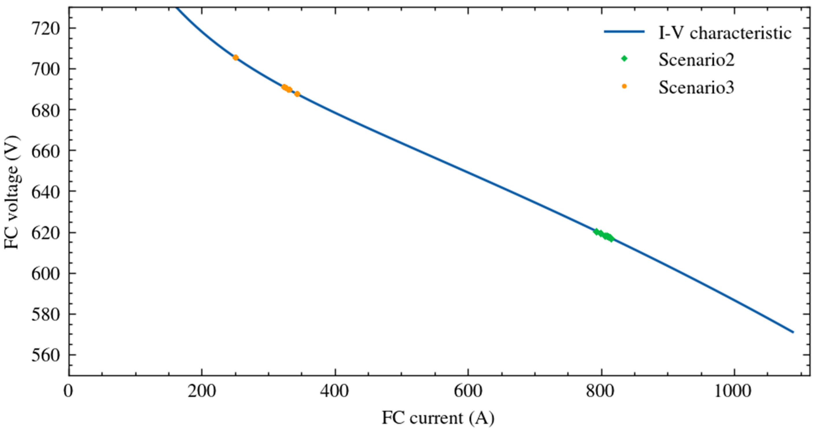
Aiming to assess whether the EMS pursued the chosen goal, the operating points of the FC were superimposed on the FC’s I-V characteristic in
Figure 12 using green color. As the figure shows, all the operating points were in the neighborhood of the point chosen by the MG designer (800 A, 621 V), confirming the correct operation of the EMS.
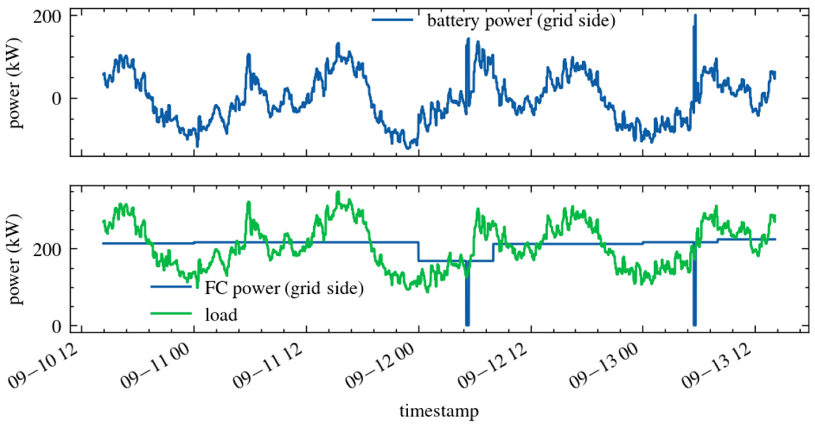
5.3. Scenario 3: EMS Operation in the Galley MG
As in the previous scenario, the simulation was performed considering that the grid energization procedure was completed. Thus, the FSM of the battery started in BATTERY_DROOP_MODE, and the FSM of the FC started in FC_CURRENT_MODE. The measured and forecasted load demand profiles over a multi-day period are depicted in
Figure 13. It can be observed that the mean power value was lower than in the previous scenario. In contrast, the variations with respect to the mean power were larger.
The MG operation was simulated over a 6-day period. The simulation period began in the afternoon, just after the black start. Therefore, also in this scenario, the EM algorithm started calculating the daily power reference for the FC until midnight, as shown in
Figure 14. Then, the power reference was recalculated every 24 h and, if necessary, at the transition between nighttime and daytime. In the considered test, the EM algorithm was able to apply the reshaping procedure with a single power reference for the whole 24-h period only on the second day. In the following days, the EM algorithm had to apply the reshaping procedure separately for day and night intervals. Nonetheless, the variation of the FC operating point was small. On September 12, power variations of about −22% and +20% occurred at about midnight and 8:00 a.m., respectively; all the other observed power variations due to reshaping procedures were minimal. It is worth noting that splitting the 24-h period into two intervals allowed for limited variations of FC power without oversizing the battery. Furthermore, the MG voltage variations were minimal according to the imposed droop resistance; the largest positive and negative variations were 1% and −1.8%, respectively, thus guaranteeing stable operation.
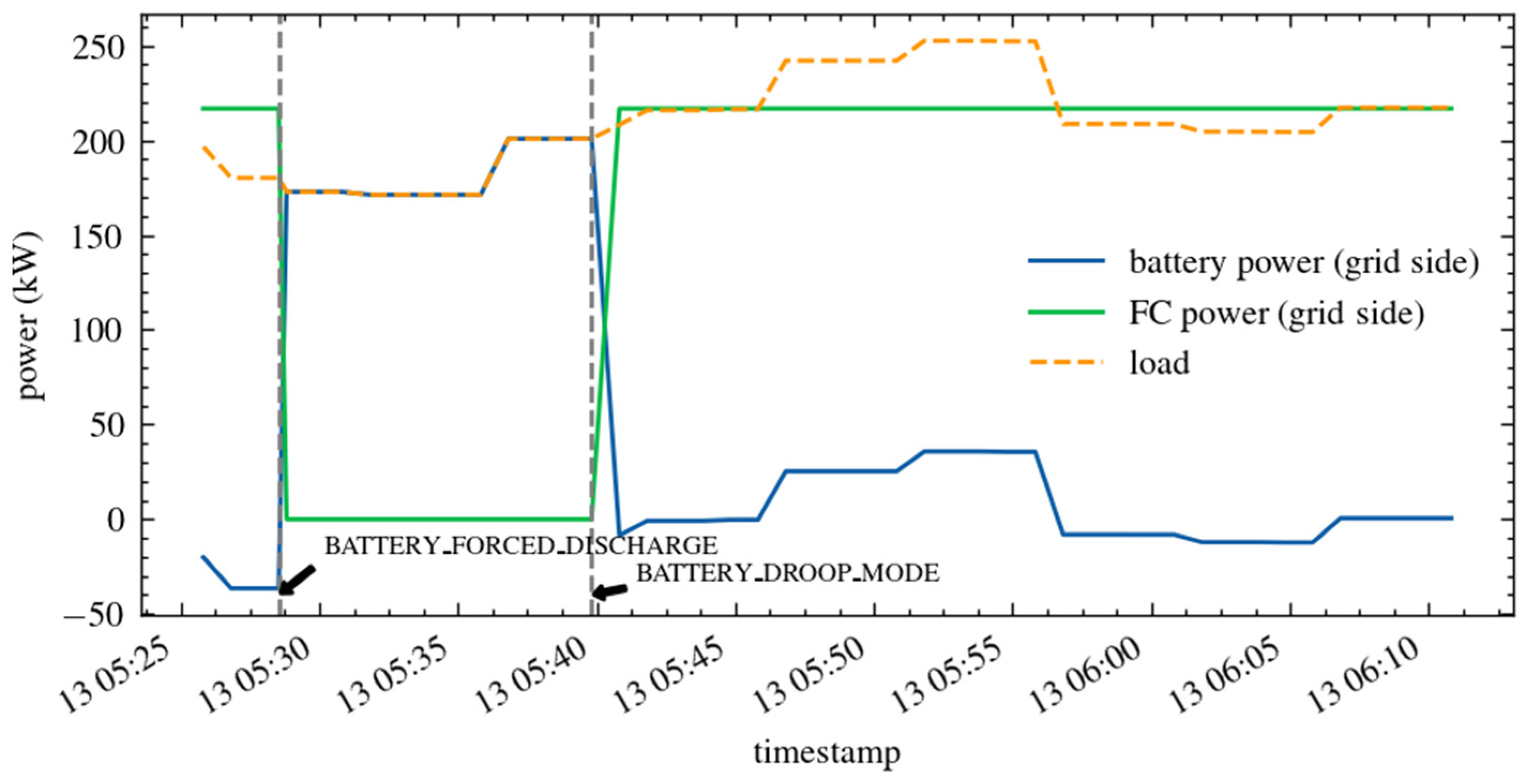
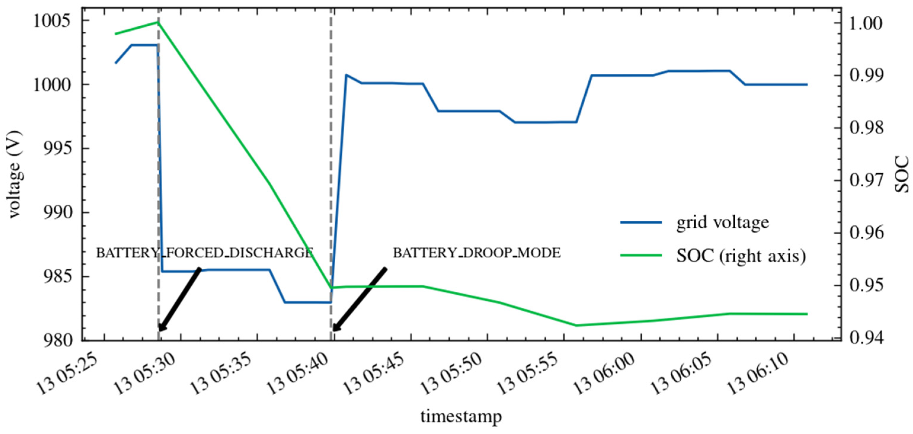
Figure 14 also shows two short time intervals of about 10 min each where the FC power was zero. These events occurred because the forecasting errors were purposely increased to test all the features of the EMS. During these events, the battery FSM bypassed the power reference for the FC and forced battery discharge. The second of these intervals (zoomed in
Figure 15) is further analyzed in the following. The load demand was lower than the forecasted load, causing battery
SOC to reach the upper limit more rapidly than expected. When battery
SOC reached 100%, a transition of the battery FSM to BATTERY_FORCED_DISCHARGE was triggered, thus imposing a null power reference for the FC.
Figure 15 highlights the time of such transition and shows the automatic increase of battery power (thanks to the droop control), which is necessary to satisfy the load demand ensuring power balance. The corresponding variations of grid voltage and battery
SOC are shown in
Figure 16.
When battery SOC decreased below 95%, the battery FSM transitioned back to BATTERY_DROOP_MODE, and the FC power reference previously calculated by the EM algorithm for the current day interval was used again. As shown, even with very high forecasting errors, the MG operation was still correct. The MG supervisor switched to temporary battery working conditions to guarantee the battery’s state of health and the MG’s power balance; then, it switched back to normal operating conditions once the temporary event was resolved.
As in the previous scenario, the battery
SOC never went below the 15% threshold, and the signal
Ibatt_too_high was never high. Finally, the operating points of the FC in Scenario 3 were superimposed on the FC’s I-V characteristic in
Figure 12 using orange color. As expected, the EMS achieved the goal of keeping all the FC operating points in the neighborhood of the point chosen by the MG designer (315 A, 692 V) while satisfying all the requirements.


 ,
, 


