Review

Energy Harvesting for Wearable Sensors and Body Area Network Nodes

1
Electrical Engineering Department, Warsaw University of Technology, 00-661 Warsaw, Poland
2
Łukasiewicz Research Network—Tele and Radio Research Institute, Ratuszowa 11 Street, 03-450 Warsaw, Poland
*
Author to whom correspondence should be addressed.
Energies 2023, 16(4), 1681; https://doi.org/10.3390/en16041681
Submission received: 2 December 2022 / Revised: 28 January 2023 / Accepted: 1 February 2023 / Published: 8 February 2023

Abstract

:
This paper aims to present new trends in energy-harvesting solutions pertaining to wearable sensors and powering Body Area Network nodes. To begin, we will present the capability of human beings to generate energy. We then examine solutions for converting kinetic and thermal energy from the human body. As part of our review of kinetic converters, we survey the structures and performance of electromagnetic, piezoelectric, and triboelectric systems. Afterward, we discuss thermal energy converters that utilize the heat generated by humans. In the final section, we present systems for converting energy from the electromagnetic waves surrounding a person. A number of these systems are suitable for use as wearables, such as RF harvesters and micro photovoltaic cells.

1. Introduction

“Ere many generations pass, our machinery will be driven by a power obtainable at any point of the universe… it is a mere question of time when men will succeed in attaching their machinery to the very wheelwork of nature” [1]—the words spoken by Nikola Tesla in 1892 are becoming a reality before our eyes. As a result of the development of photovoltaic panels and wind turbines, we are now able to generate energy on a macro scale. Additionally, it is possible to produce energy on the micro scale by utilizing laws and phenomena that have been known for over a century, such as Faraday’s Law, Setback’s phenomenon, the Peltier effect, Maxwell’s equations, and piezoelectric and magnetic materials (from more recent ferrofluid).
Energy-harvesting (EH) methods enable the development of self-powered systems, which are often used in Wireless Sensor Networks (WSNs) or as edge nodes in the Internet of Things (IoT). Research and review articles on energy harvesting have significantly grown in number over the past decade, suggesting that the technology has gained many novel applications. An overview of the EH application in industrial contexts is presented in the literature [2,3,4], while in structural monitoring and civil engineering applications, we have the following review papers [5,6,7,8]. Of course, self-priming sensors also have their place in environmental protection [9,10,11]. The same is true in medicine [12,13,14,15].
The topics of our article are similar to EH applications in medicine and wearable sensors. Significant attention is also paid to practical harvester solutions built and tested by the authors. Our review is unified by the idea of “the human” as an object that generates energy, but also as an organism that is monitored by the sensor nodes of the Body Area Network (BAN). Given the above, our article is further structured as follows. Section 2 provides an overview of the energy capabilities of the human body. It begins with an explanation of the processes that allow humans to generate and transform energy into amounts that are suitable for conversion to electrical energy. In Section 3, we present an overview of the power systems and harvesters that convert kinetic and thermal energy from the human body. The method by which electromagnetic waves can be converted into electrical signals is discussed in Section 4, where radio frequency harvesters and solar harvesters for wearable sensors are discussed. Section 5 summarizes the overview presented in the previous sections.

2. The Human Body as an Energy Generator

Human bodies are systems that convert food into energy through metabolic processes for the maintenance of life processes and for the performance of muscle contractions and other functions. The process of the oxidation of organic molecules that breakdown chemical bonds also releases thermal energy. As a result of the process of thermoregulation, some thermal energy from the body may be released into the environment. Using the averaged formula (1) presented by Kleiber in 1947, a body’s energy expenditure associated with maintaining all human life processes can be calculated based on the Basal Metabolic Rate (BMR) or metabolic rate [16]. This value can be calculated under standardized conditions, such as fasting in the supine position 12 h after a meal at 24 °C. According to the cited studies as well as later ones [17,18,19], metabolism changes as we age and reaches its peak during the third decade of life when an individual’s organizational capacity is at its highest. The metabolic rate is generally not affected by the amount of body fat present, but is somewhat affected by gender. Changes in physical activity can increase the metabolic rate by as much as 12 times in a short period of time [19]. This corresponds to a proportional increase in the total amount of heat energy that the body emits.
H kJ / day = 293 W 3   4
where:
H kJ / day —daily rate of heat production (kJ/day);
W—mass of body (kg).
In Figure 1, the heat power given off by the human body is plotted as a function of mass. As an example, a person weighing 80 kg emits 7.84 MJ of heat energy per day, which is solely necessary for the maintenance of metabolic processes. In terms of average daily power, this equates to 90.7 W.
Food, water, and oxygen are essential for animals, including humans, in order to produce energy. Based on the chemical composition and physical properties of the food supplied to an organism, it is relatively easy to calculate the energy content of the food. The heat that is produced when food is burned in a bomb calorimeter is considered to be a generally accepted measurement of the energy value of food [17]. In this process, a waterless product is burned with pure oxygen at a pressure of several tens of atmospheres—the standard is 30 atm. The energy content of food is determined by its combustion conditions, which are considerably different from those found in the human body during metabolism. The amount of energy supplied to the body based solely on the caloric content and weight of food can be referred to as gross energy. The term metabolic energy refers to the energy obtained by the body as a result of digestion and metabolism. Energy contained in metabolic products is reduced in comparison with gross energy. It is necessary to take a portion of metabolic energy in order to maintain a constant body temperature as well as sustain cellular oxidation processes. Additionally, the body requires energy to carry out digestive processes, which are referred to as food-induced thermogenesis. Net energy is the remainder, which can be used by the body to produce muscle contractions. It is pertinent to note that the overall distribution of the above energy is dependent on human activity. Table 1 shows the portion of energy expenditure that is associated with each vital function of the body according to Keller’s study [16].
In order to determine the intensity of physical activity, the Metabolic Equivalent of Task (MET) is used to estimate the multiple of energy expenditure related to muscle work as compared with resting energy expenditure. The resting energy expenditure is 1 MET. It is estimated that 1 MET corresponds to the consumption of 3.5 mL of oxygen per kg of body weight in one minute, which equates to 1 kcal/(kg b.w./min), e.g., 1.2 kcal/min for a man weighing 70 kg or 1.0 kcal/min for a woman weighing 57 kg, according to [19]. Using the above scale, human activity can be classified as:
  • Low-intensity activity < 3 MET;
  • Medium-intensity activity (3–6) MET;
  • High-intensity activity > 6 MET.
Table 2 shows examples of energy consumption (net) at different types of physical activity [17,19,20].
In addition to understanding how the human body operates, we also know what the main sources of energy are. We also know how much energy is required to sustain life processes and activities. Using the energy balances of physiological and metabolic processes, it is possible to determine how effectively net energy can be produced by the body. As a result, the question arises: how much energy from a person’s total energy balance can be converted into electricity and used to power the devices or systems accompanying them?
Energy-harvesting techniques can be used to answer this question. From the considerations discussed above, it appears that the body’s thermal energy is the most important source of energy. However, kinetic energy from typical activities is another source of energy for EH systems worth consideration. It has been shown that the human body is able to generate energy [21,22,23,24]. The compilation presented in Table 3 indicates that thermal energy is permanently transferred to the environment. However, it is relatively inefficient when it comes to generating electrical power. Our review of practical solutions will begin with the conversion of kinetic energy, which provides superior efficiency.

3. Kinetic- and Thermal-Energy-Harvesting Technique Dedicated to BAN

3.1. Electromagnetic Energy Harvester

In systems converting kinetic energy into electrical energy using an electromagnetic harvester, we rely on a design in which the change in magnetic flux involving the conductor is forced. If the conductor is winding, then the electromotive force (E) induced at the ends will follow directly from Faraday’s law and will be proportional to the number of windings (n) and the rate of change of flux ( Φ ) over time (t), which can be written with the Formula (2):
E = n d Φ dt
The instantaneous power (P) generated by the system can be expressed by Formula (3):
P = n d Φ dt 2 · R 0 R 0 + R s 2
where:
R0—resistance of load;
Rs—resistance of electromagnetic harvester.
In order to make effective use of the obtained power, the output signal from the harvester must be rectified. Typical rectification circuits are shown in Figure 2. The conversion systems used can be divided into linear classic and nonlinear (SSHI, SCE). A linear circuit (Figure 2 left) can be built from the rectifier alone, sometimes in addition to a DC/DC circuit. Impedance matching is used to optimize generated power. This has the advantage of simple construction and low-output-voltage ripples.
Nonlinear circuits include SSHI (synchronized switch harvesting on inductor) and SCE (synchronous charge extraction), and both are characterized by more sophisticated circuits compared to the classic ones. They contain nonlinear elements, such as a inductor and switch. The switches are commonly constructed as electronic MOSFET keys working in a so-called self-powered configuration; therefore, they do not require an additional, dedicated power source, which would otherwise significantly decrease efficiency. The function of the switch is to separate and simplify the working circuit during the charging and load operating phases. What is more important, synchronized switch operations allow to increase both the generated power and voltage. As an example, in the presented SCE circuit (Figure 2 on the right), the switch is opened until the maximum voltage is reached and detected. Then, it closes and energy is stored in the coil until the voltage passes zero. When it opens again, the stored energy supplies the load (and only the load). Switching solutions allows a fourfold increase in output power compared with the linear method [25,26]. However, they are also characterized by large ripples in the rectified voltage. When rectifying a signal, the problem is the amplitude of the generated voltage, which is usually below the threshold voltage of diodes in linear circuits. SCEs and SSHIs work most effectively for sinusoidal signals when the switches are accurately driven. In contrast, real signals are often random, with small amplitudes and varying frequencies.
The construction of electromagnetic generators can be divided into linear and rotary. Linear generators use naturally occurring vibrations. They are usually built with a tube on which a coil is wound, and a permanent magnet mounted on springs is placed inside it (Figure 3). Instead of a mechanical connection, magnets are also used. Rotary generators are built with two main parts: a stationary stator and a rotor. Both are usually made in the form of cylinders. Coils are placed on one of them, and permanent magnets are placed on the other.
Article [27] presents a linear harvester where a magnet moves in a column that is about 11 cm long between two windings 2 cm apart. The maximum voltage at the open output is 25 V and is obtained at a frequency of 22 Hz. The authors note that the choice of remnant flux of the levitated magnet affects both the amount of power generation and the location of the frequency jump while the height is stationary. Gao et al. in [28] present a family of nonlinear harvesters. For a structure with 4 magnets moving at a distance of 26 cm, they obtain as much as 440 mW at a vibration frequency of 5–12 Hz.
Zheng et al. presented three harvesters in [29] dedicated to converting energy from human motion. Each harvester consists of an array of 6 to 16 linear small harvesters using a 200-winding coil and a single magnet. The most efficient array with 16 harvesters with a total weight of 180 g suspended from a backpack under a running speed of 2.8 m/s achieved 14.8 mW. Li et al. presented two solutions for a harvester positioned above the ankle. The first solution [30] uses a double winding and a single magnet mounted on springs moving in a carbon-fiber tube. The magnet is covered with ferrofluid. The total weight of the harvester is 80.5 g. The power obtained when running at 10 km/h was 9.5 mW. In the second solution [31], the authors modified the design, and used three separate windings and a stack of four neodymium magnets. The authors noted that covering the magnets with ferrofluid increased the output power from 17.72 mW to 54.61 mW.
Samad et al. in [32] presented a harvester which is installed on a forearm. The harvester measures 21 cm and weighs 140 g. The neodymium magnet, which is 24 × 15 mm, moves along a curved track, allowing the use of two axes during hand movement while running. The magnet moving produces an electromotive force in a coil of 1000 turns. The maximum value of the induced electromotive force was 4.07 V, while a power of 5.18 mW was obtained when walking at a speed of 1.8 m/s.
Mintura and Kecik presented in [33] a linear harvester system in which 2 mutually levitating magnets are placed in a 18 cm long tube. For a frequency of 10 Hz, the magnets moved at a speed of 0.7 to 1.1 m/s. Under these conditions, the system gene-rated power at 110 mW with a 2 kΩ load. On the other hand, in [34], a harvester was presented in which the magnet had the shape of a sphere moving in a tube on which two windings were wound. The system generated 80µW when vibrating slightly below 1 Hz.
A rotary electromagnetic harvester system has a structure where the magnates rotate over the winding or vice versa. This is the design of the harvester described in [35], shown in Figure 4.
What we see here is a 19.6 mm × Φ100 mm structure with 12 alternating neodymium magnets spinning between 2 × 12 windings. The system is dedicated for mounting on an arm and is optimized for low vibration frequencies. At a center frequency of 2 Hz, the chip is capable of generating 74 mW. In the wider frequency band of 1.5–3 Hz, the average power value is 8.37 mW. A similar arrangement of magnets can be observed in [36], which shows a rotary arrangement of six pairs of magnets placed over a coil. The rotation of the array can be enhanced with a torsion spring (torsional spring) Depending on the placement of the array, which can be on the wrist or ankle, a power ranging from 10 µW to above 200 µW could be obtained, respectively. In [37], on the other hand, the authors presented a watch-sized array in which a magnets in the shape of a flat cylinder rotate over an array of 4 coils, in which case a power density of 0.2 mW/cm2 was achieved, which, with a 32 cm2 area, yields 6.4 mW.
In [38], Xue et al. presented a watch-sized system in which a commercial Kinetron microgenerator system was used for power generation. The system allowed for a power generation of more than 400 µW when running at 9 km/h. By contrast, during typical human operation in an office, the system generates more than 40 µW. The same harvester was used in [39]. When mounted on the wrist, a power output of 420 µW was achieved, while on the ankle, 649 µW was achieved during human running. An appropriate selection of the Negative Voltage Converter circuit allowed achieving 84% efficiency.
Wang et al. in [40] presented a system where a rectangular array of magnets is suspended by a ferrofluid-based bearing over a single-layer winding. The authors note that the use of ferrofluid reduces friction in motion. In addition, the system does not work out of resonance because of its effective operation in low frequencies, such as 2–4 Hz. The system assembled on the back of a man running at a speed of 3.6 m/s is capable of generating energy of 18.1 µW.
An interesting solution is the harvester presented by Bao et al. in [41]. Here, four windings were mounted on the walls of a square housing. The change in the magnetic field was provided by the spinning of six neodymium magnets in the center of the two-windings. The magnets are set in motion by converting reciprocating motion into rotating motion. The entire harvester is mounted under the sole of the shoe. During a typical walk (1 Hz vibration), an output power of more than 32 µW is possible.
Kawa et al. [42] presented a micro harvester with dimensions of 20 mm × 10 mm × 6 mm and whose structure is shown in Figure 5. This circuit is capable of generating 20 µW at vibrations above 100 Hz.
On Table 4 we present a comparison of electromagnetic harvesters with base parameters.
Comparing the solutions and types of harvesters, rotary generators generate energy with greater density, so they can be smaller in size. Linear generators, on the other hand, are characterized by simpler construction and easier adaptation to natural sources of kinetic energy. The amount of energy generated by the generator depends on the coil design and the magnet used. Coils are made in the traditional way of winding wire or as a path on a PCB. In the case of the traditional approach, attention should be paid to wire diameter, total length, or number of turns. A higher number of turns allows generating a higher voltage; however, it increases the resistance of the coil. Once the resistance limit is exceeded, a further increase in the number of turns will not increase the generated voltage. The resistance is also affected by the diameter of the wire. For several-centimeter devices, we used wire with a diameter of 0.1 to 0.5 mm. A larger diameter reduces resistance at the expense of a larger overall device size. Thus, a compromise between the number of turns and the diameter of the wire is required to obtain as much energy as possible.
On the other hand, the value of magnetic induction depends on the magnet. The strength of the magnetic field generated depends on the material from which the magnet is built. The most common materials used for their construction are nickel–cobalt, copper, iron, and titanium alloys (alnico magnets); iron oxides; barium oxides (ceramic magnets); or rare earth elements (samarium–cobalt and neodymium magnets). Neodymium magnets are characterized by the strongest field produced. Their disadvantage, however, is their low maximum operating temperature of about 120 °C compared with the rest. However, it is sufficient for energy-harvesting applications; therefore, neodymium magnets are the most widely used. Recently, there has been a trend to coat magnets with ferrofluid-type magnetic fluids, increasing induction and reducing friction to increase the motion of the system.

3.2. Piezoelectric Harvesters

In harvesters that obtain energy from the environment using piezoelectric materials, the properties of the simple piezoelectric effect are used. A frequently used construction is a vibrating beam with a vibrating mass attached to it and a piezoelectric transducer, as shown in Figure 6:
The natural frequency of such a beam can be determined from Formula (4) [43]:
ω = k m = 3 EI 33 140 m 1 + m 2 L 3
where:
k—stiffness coefficient of the cantilever beam;
m—beam mass;
E—Young’s modulus [Pa];
I—geometric moment of inertia of the beam [kg × m2];
L—length of the beam [m];
m1—mass of the beam [kg];
m2—mass of the weight [kg].
One of the most commonly used piezoelectric materials is PZT ceramic [44,45]. This material is made of lead titanium zirconate and is characterized by high performance and easy availability. Paper [45] describes a hybrid piezoelectro-magnetic energy harvester that extracts mechanical energy from walking and running, converting it into useful electrical energy. The system responds to very low numbers of walking steps at a frequency of 3 Hz, causing the central spiral spring carrying the magnetic masses to vibrate at a frequency of 8 Hz (the first resonant frequency), generating a voltage through electromagnetic induction. At the same time, the input mechanical excitation causes deformations in the piezoceramic plates, resulting in a piezoelectric voltage on the top and bottom PZT plates. The combiner generates peak power at four resonant frequencies, covering a wide range of operating frequencies. Maximum average powers of 656 µW and 744 µW were obtained for the upper and lower coil windings at the first resonant frequency and at 0.5 g acceleration, with load resistances of 39 Ω and 48.5 Ω, respectively. Peak powers of 73 µW and 196 µW were generated with an optimal load resistance of 330 Ω on the top and bottom PZT boards at 51 Hz and 0.5 g acceleration, respectively.
Article [46] presents a multi-element piezoelectric power harvester with a magnetic-force-driven part. To improve the electric power density coming from the mechanical vibration of the environment, the authors used the frequency up-conversion technique. The harvester uses a combination of a multi-stage mechanisms and a bistable structure. A multi-stage mechanism in the form of a matrix of magnets with variable magnetic poles was designed for the energy-harvesting system to achieve a wide operating bandwidth. The experimental results show that the open-circuit output voltage of the harvester is 4.4 V. The harvester generates a peak power of 5.0 μW into a 3.3 MΩ resistive load at a frequency of 3.0 Hz.
Article [47] presents a piezoelectric energy harvester from human motion by impact. The authors chose a high-frequency bimorph beam made of PZT-5A material with a mass mounted at the end. Energy conversion was realized using the impulse force from human motion. The aluminum prototype was connected to the leg of a person on a treadmill and electrical energy was measured during multiple repetitions in relation to gait speed. The external dimensions of this prototype were up to 90 mm × 40 mm × 24 mm. The authors showed that the average output voltage increased sequentially with increasing walking speed. The maximum voltage was 2.47 V, and the maximum average power of 51 μW can be achieved with a power signal resistance of 20 kΩ and a walking speed of 5 km/h. The experimental results show that the shock-induced piezoelectric energy-harvesting system on the leg can power the Body Area Network device.
Article [48] presents an inertial device in the form of a piezoelectric beam with a magnetically coupled seismic mass. The system was mounted on a rotating mass, and is presented on Figure 7. In the frequency range from 0.5 Hz to 4 Hz, and with accelerations from 1 to 20 m/s2, output power in the tens of microwatts was obtained, with a peak value of 43 μW at 2 Hz and 20 m/s2.
In a subsequent article [49], the authors demonstrated that the PMN-PT flexible single-crystal piezoelectric energy harvester makes it possible to power an artificial pacemaker. The energy-harvesting device generates a short-circuit current of 0.223 mA and an open-circuit voltage of 8.2 V, which are not only sufficient to meet the commercial battery charging standard but also to stimulate the heart without an external power source.
Article [50] presents the design, simulations, and experimental studies of an innovative piezoelectric energy-harvesting device with a two-stage mechanism to amplify the force acting on the human gait energy harvester. The harvester consists of four piezoelectric transducers sandwiched between two plates shaped similar to flat springs. The dynamic reaction force to the pressure of the human foot is amplified twice by the two-stage frames, resulting in a high power output. From the simulations described in the paper, under a dynamic force of 500 N and a frequency of 3 Hz, an average power of 34.3 mW and a peak power of 110.2 mW were obtained. At 2 Hz and 1.0 Hz frequencies, average output powers of 23.9 mW and 11.0 mW, as well as peak output powers of 65.8 mW and 31.7 mW, were obtained experimentally. Numerical simulations showed that an average output power of 12.8 mW and a peak output power of 204.7 mW could be obtained at a walking speed of 5.6 km/h from a man weighing 84 kg that is 172 cm in height. Comparative studies have shown that the proposed two-stage piezoelectric combiner has higher output power than the results of similar systems presented in the literature.
A recent article on piezoelectric harvesters [44] presented a harvester that recovers the energy transferred to the ground during daily walking. A shoe sole was designed, in which various piezoelectric materials were placed. Using computer programs, the operation of the system was observed under the influence of human weight. The authors conducted parametric analyses using piezoelectric ceramics deformed by the weight of humans of 50, 60, 70, 80, and 90 kg. PZT-5H and PZT-8 materials were analyzed, and a PZT-5H piezoelectric material integrated with a human shoe was selected. It was shown that for a 90 kg human, up to 1.43 mW of electrical energy can be obtained from the applied force. Table 5 shows a comparison of the piezoelectric and hybrid combiners presented.

3.3. Triboelectric Harvesters

Triboelectric harvesters take advantage of the electrostatic phenomenon that occurs at the contact between two materials that are at the ends of a triboelectric series. The general structure of a triboelectric harvester is shown in Figure 8. The triboelectric series classifies materials based on polarity and the amount of charge created when different materials come into contact and separate. In the construction of systems that extract energy from the environment, the authors of articles [51,52] most often use materials such as aluminum and silicone rubber. The mechanical energy of human motion moves the layers of these materials, resulting in the generation of electrical charges. A characteristic feature of such systems is the generation of a high voltage of several hundred volts with a current output of several hundred nanoamperes.
The authors of article [51] conducted research on a hybrid harvester that combines piezoelectric elements and triboelectric layers in its design. This circuit design improves performance and extends the operating frequency range. A prototype of the device has been described and tested in real conditions, in a human run and in laboratory conditions. During the tests, it was confirmed that such a device can operate in multiple frequency ranges and orientations. In the frequency range of 0.5 to 4 Hz and accelerations of 1 to 20 m/s2, output power in the tens of microwatts was obtained, with a peak value of 43 μW at 2 Hz and a continuous acceleration of 20 m/s2.
In a subsequent paper [52], the authors presented a flexible, single-electrode, high-performance hybrid tribo-piezoelectric nanogenerator similar to the one presented earlier. Thanks to the integration of a silicon rubber (SR) layer and a BaTiO3/SR functional layer, as well as the low Young’s modulus of the metal electrode, the harvester retains very high elongation at break (745%) and excellent conductivity (0.72 Ω) at high loads. At the same time, the introduction of BaTiO3 ferroelectric ceramics greatly improved the dielectric constant of the highly tribo-negative SR layer, which combined with the polarization process results in a piezoelectric charge transfer that occurs in a contact–separation cycle, leading to a 50% improvement in performance. An SEP-TENG (single-electrode piezotriboelectric hybrid nano generator) with improved efficiency generates a high peak output voltage and power density of 1200 V and 5.7 W/m2, respectively. This energy is sufficient to illuminate LEDs, charge capacitors, and power wearable electronics. In addition, thanks to the high piezoelectric power in the device model, the miniaturized tribo-piezoelectric SEP-TENG can be used as a smart energy-harvesting patch when bending and monitoring human body movement. The work carried out shows that the energy conversion efficiency is improved and the multifunctional SEP-TENG can be used for energy harvesting and motion detection, indicating great prospects for the innovative design of a new generation of flexible wearable electronics.
The authors of the article [53] present an approach in which triboelectric nanogenerators (TENGs) represent a new technology for extracting energy from human motion. Flexible, portable, and self-powered electronic devices based on TENGs are in high demand; however, complex preparation processes and the high cost of traditional flexible energy electrodes hinder their practical application. This paper presents a MXene/polyvinyl alcohol (PVA) and TENG hydrogel (MH-TENG), which are characterized by simple production, high performance, and versatile applications. MXene doping promotes the crosslinking of the PVA hydrogel and improves the extensibility of the composite hydrogel. MXene nanoparticles also form microchannels on surfaces, not only improving hydrogel conductivity by enhancing ion transport but also generating additional triboelectric power through a flux potential oscillation mechanism. The measured open-circuit voltage of the MH-TENG reaches up to 230 V in single-electrode mode. The MH-TENG can be stretched to 200% of its original length and exhibits a monotonically increasing relationship between stretch length and short-circuit voltage. Taking advantage of the MH-TENG’s exceptional stretch and very high sensitivity to mechanical stimuli, the article presents applications in monitoring body motion, precise stroke recognition, and low-frequency mechanical energy harvesting.
In [54], the authors focus not only on the design of the device but also on its effects on the human body. They developed a durable and body-fitting skin-like TENG (LS-TENG) single electrode, with Aloe Vera Gel (AVG) NaCl as the power electrode. A source electrode with high conductivity and tensile strength was chosen as an efficient channel for charging operations, resulting in a high energy yield that is 2.1–23 times higher than other LS-TENGs after studying the effect of molecular electrode size in LS-TENG, based on which the output parameters are optimized. Thus, the AVG NaCl-based LS-TENG exhibits higher output power than the LS-TENG, generating an open-circuit voltage of 157.8 V and a current of 44.2 mA/m2, corresponding to a power of 4.61 W/m2. In addition, the device provides stress sensitivity and can be generated in 2D or 3D, which has great potential for wearable electronics, such as e-skin.
Robust, self-powered sensors that are expandable, self-adhesive, and transparent are in high demand for next-generation electronics/energy/robot applications. Paper [55] presents a process for creating a solid-state triboelectric patch using a polyethylene oxide/polyurethane/water/phytic acid composite (PWP composite) as an efficient current generator and silicone rubber as a triboelectric element. The PWP composite is the optimal solution, where the device can be integrated with a single electrode of 2.3 W/m2 at a 75% load. The triboelectric patch is able to charge capacitors and power electronics by harvesting biomechanical energy. In addition, it can be autonomously attached to non-flat skin or clothing and used as a switching sensor or panel with touch and remote operation. Even after dynamic deformation and long-term use, the patch can provide good performance and electrical energy. This paper presents a special triboelectric nanogenerator for polion electrode operation capable of an epidermal effect. The harvester can be used to power electronics, e-skin, and smart health-monitoring interfaces.
A completely different approach to the state of the triboelectric layer is presented by the authors of [56]. According to them, there is growing research interest in the use of hydrogels. However, the decrease in the conductivity of organohydrogels due to the introduction of an insulating solvent has limited their use in electronics. The researchers demonstrated the Hofmeister effect and electrostatic interaction to form hydrogen and sodium bonds in the hydrogel. Combined with a double lattice, an efficient energy source is created that is unaffected by the addition of solvent. The developed one-electrode triboelectric nanogenerator based on organohydrogel (OHS-TENG) shows a small decrease in conductivity (by one order) and high efficiency (1.02–1.81 W/m2), and these parameters are much better than other known OHS-TENG (decrease in conductivity by 2–3 orders and efficiency of 41.2–710 mW/m2). In addition, the replacement of water with glycerol in the hydrogel provides excellent long-term stability (4 months) and temperature tolerance (−50–100 °C). The presented mechanism can be used in common organohydrogel systems to achieve high efficiency in electronic applications, such as human body energy harvesting.
In [57], the authors developed an easy-to-make insole that generates energy from the pressure of the foot on the sole of the shoe (Figure 9). This insole works with a technology called a triboelectric nanogenerator, which converts pressure into electrical energy. TENG’s thin and multilayered structure not only provides high power output density but also flexibility. Triggered by human body pressure, the TENG produces an open-circuit voltage of 220 V and a short-circuit current of 600 µA. Based on the power-generating insole, a fully functional shoe equipped with LEDs powered directly during normal walking was created. In addition, the authors designed a system that provides a convenient way to charge consumer electronics. This work shows that TENG is a practical and implementable technology that can be used to develop self-powered products for everyday use.
Comparison of triboelectric harvesters are presented in Table 6.

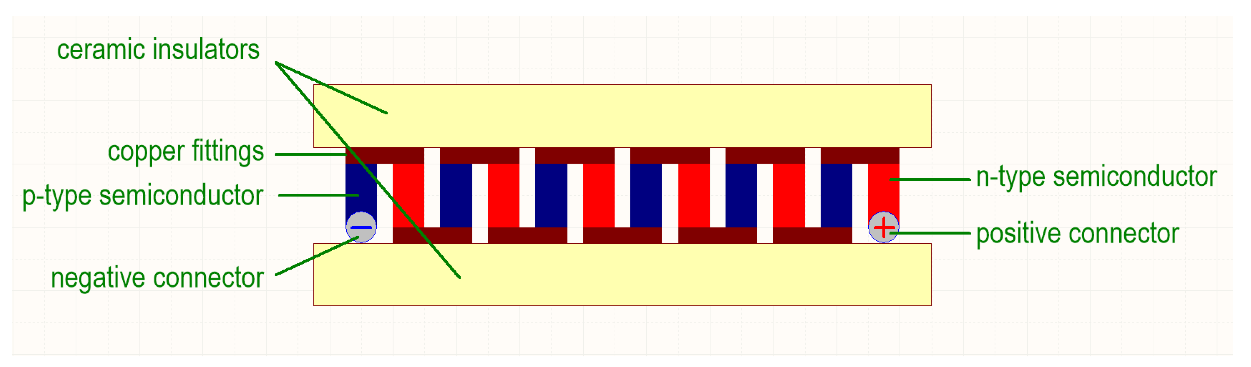
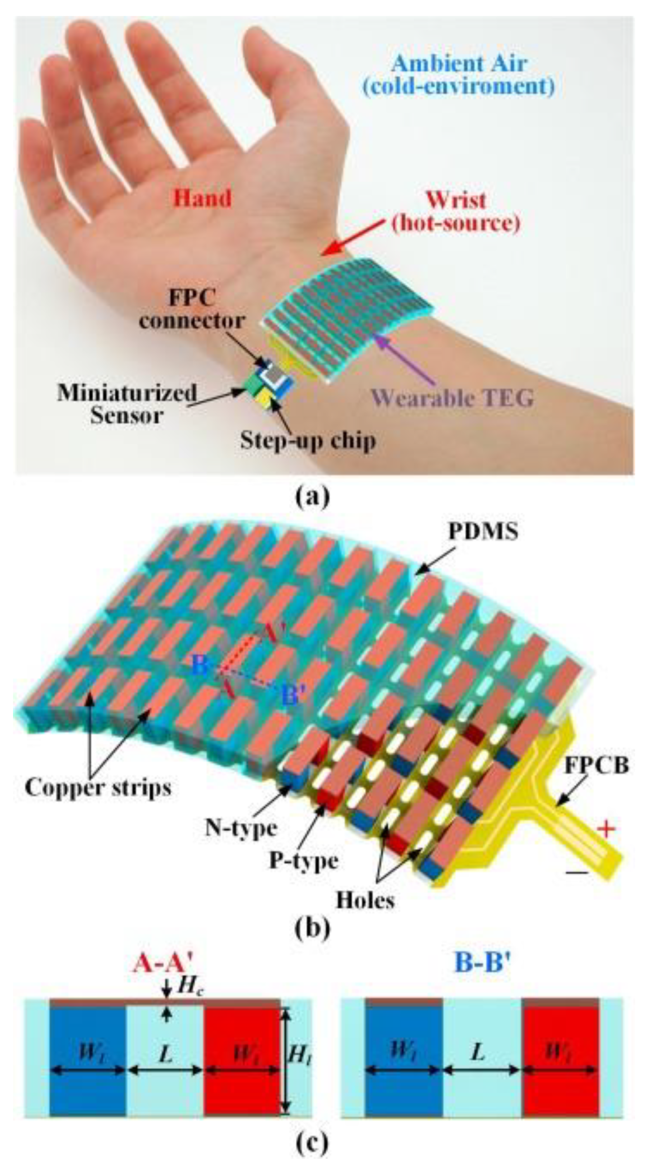
3.4. Thermogenerators

Thermogenerators (TEGs) work on the principle of the Seebeck effect, which is the opposite of the Peltier effect. The Seebeck phenomenon involves the creation of an electromotive force between semiconductors whose junctions are at different temperatures. The Peltier effect involves the absorption and release of energy between semiconductor junctions under the influence of an electric current flow. The Seebeck coefficient is described by Formula (5):
a = Δ V Δ T
where:
a—Seebeck coefficient [µV/K];
ΔV—electrical voltage difference [µV];
ΔT—temperature difference between semiconductors [K].
Peltier cells have gained popularity in portable low-power cooling devices. When we create a temperature difference between their semiconductor junctions, they can be successfully used in systems that extract energy from the temperature difference between the environment of 21 °C and the human body with a constant temperature of 36.6 °C. The structure of the Peltier cell is shown in Figure 10:
In the article [58], the authors analyzed TEGs in the specific context of heat recovery from human skin. The operating conditions of these TEGs are not conventional, especially since the temperature, and therefore the gradient on the generator disks, is very low (human body, Tb = 37 °C) and the source is cold (environment, Ta = 22 °C). The authors proposed several ways to improve electrical efficiency, which were verified experimentally. They initially measured that the power of three stacked heat sink modules is about 7 μW/cm2 when the user is stationary and 30 μW/cm2 when the user is moving at a speed of 1.4 m/s. The authors’ research shows that it is better not to optimize the efficiency of the harvester by increasing the voltage at its terminals, which is associated with an increase in the temperature gradient; instead, higher harvester efficiency can be achieved by minimizing losses in the DC–DC converter, thus maximizing the overall efficiency of the system.
A completely different approach to TEG was presented by the authors of another article [59], who successfully developed and tested a flexible thermoelectric energy storage (f-TEG) device using PVDF/Bi2Te3–TE-composite films for wearable devices. The TE films were fabricated by a simple drop-casting process using Bi2Te3 powder. The TE film as a p-type semiconductor with 75% Bi0.5Sb1.5Te3 and the TE film as an n-type semiconductor with 80% Bi2Te2.7Se0.3 showed the highest power factor values of 133 μWm−1K−2 and 124 μWm−1K−2, respectively. Finally, the large-area f-TEG generated a maximum power of ~12.6 nW at ΔT = 25 K. The TE efficiency increased with increasing ΔT. In addition, the authors conducted FEM simulations that verified the theoretical thermoelectric potential distribution of the PVDF/Bi2Te3-composite-film energy-harvesting device. To demonstrate its application in wearable devices, the f-TEG was attached to a mask and used to measure electrical signals generated by human body heat during breathing. The f-TEG wearable produced electrical signals with an output current and voltage of 0.38 µA and ≈2.3 mV, respectively. The presented f-TEG could find application in health monitoring and Internet of Things (IoT) devices. The paper presents the development of a potential material for smart wearable electronics and energy-harvesting technology using human body heat energy.
Paper [60] presents the design and implementation of a high-power-density TEG for extracting human body heat energy. The proposed TEG was fabricated using a flexible printed circuit board (FPCB) as a substrate. Blocks of p-type and n-type semiconductors were made of Bi2Te3-based thermally conductive material and attached to the FPCB, then surrounded by soft polydimethylsiloxane (PDMS) material. The TEG prototype consisted of 18 semiconductor junctions, which were connected using FPCB and silver paste in a 42 × 30 mm2 area. The fabricated TEG could generate a voltage of 48 mV for a temperature difference of 12 K. The authors then tested the TEG on the skin of a human wrist to collect human body heat energy. The results showed a measured output power of 130.6 nW at an ambient temperature of 25 °C. Therefore, the developed TEG has the potential to harvest human body heat energy and can be used to develop portable self-powered devices.
The authors of another article [61] examine the effectiveness of a commercial TES1-12704 module for extracting thermal energy directly from the human body. During basic locomotion activities, the generator output ranged from 5 to 50 µW. Placing the TEG on the leg can also be helpful in identifying locomotor activities because leg temperature and muscle thermals can be directly related to various activities, such as walking or running. The results obtained in the presented work suggest that extracting energy from lost leg heat may be an emerging trend in the design of smart wearable devices that are useful in various applications, such as human security, e-health, telemedicine, rehabilitation, and wellness.
In [62], the authors propose an advanced material as the building block of a stretchable carbon nanotube/polyvinylpyrrolidone/polyurethane (CNT/PVP/PU) composite, a fabric with excellent stretchability and air permeability that is capable of extracting energy from human body heat. They propose to use PVP as an aqueous binder and dispersant to improve CNT dispersion, thereby increasing the bond stability between CNT and PU nanofibers. The maximum Seebeck coefficient and power factor of the composite fabric at room temperature can reach 51 μVK−1 and 5.14 μWm−1K−2, respectively. In addition, the composite fabric has ultra-high deformation strength (~250%) and an air permeability of 425 mm/s at 300 Pa. Moreover, the described device, consisting of 5 composite fabrics connected in series, can be mounted directly on the arm to generate a voltage of 0.75 mV at room temperature. In addition, the authors have equipped this combinator with a deformation sensor that monitors the movements of human joints for an optimal movement position. The presented CNT/PVP/PU-thermoelectric-composite fabrics show great potential in the fields of wearable electronics, such as e-skin, human–computer interaction, and health management.
The authors of paper [63] focused on wearable thermoelectric generators (TEGs) and presented a new wearable TEG with 52 pairs of cube-shaped thermoelectric blocks for collecting human body heat. The thermoelectric blocks are made of Bi2Te3-based powder materials, and p-type and n-type semiconductors are connected in series by soldering. The authors describe a flexible printed circuit board (FPCB) with special holes, which was used as a substrate to make the TEG flexible for attachment to the human body. Preliminary results show that the TEG can generate an open-circuit voltage of 37.2 mV at ΔT = 50 K, and the TEG’s internal resistance is quite low at 1.8 Ω. The TEG was then mounted on a human wrist to collect body heat and power a 3-axis miniaturized accelerometer to detect body motion at ΔT = 18 K. The results presented here show that the developed and worn TEG has high output efficiency and can be used to power electronics or sensors from human body heat. Structure of described harvester and place of installation are presented on Figure 11.
Comparisons of a thermoelectric harvester are presented in Table 7.

4. Energy Harvesters Using the Power of Electromagnetic Waves

In open space, radio signals travel at the speed of light and propagate indefinitely. It is possible to harvest their energy directly in the vicinity of the antenna, which is known as the near field. In some consumer electronics, such as mobile phones and earphones, this method simplifies their construction by removing the physical plug for charging.
In contrast, a requirement for BAN applications to keep a wearable device near the source of the radio frequency signal while being stationary would be infeasible. Thus, such devices need to capture energy from the far field that spreads beyond d f , also known as the Fraunhofer distance (6):
d f = 2 D 2 λ
where   D   is the dimension of a radiating antenna, while λ is the wavelength of the transmitted signal. We can conclude from the equation that the wavelength should be as large as possible. It should be noted, however, that the dimensions of antennas are positively correlated with wavelength, so the longer the waves become, the less practical they are as antenna sizes increase. Furthermore, the receiving device should not require a specialized wireless power transmitter to harvest RF energy. It is advantageous to harvest energy from existing, popular communication systems, such as WiFi, mobile telephony, radio communication in the ISM bands, and television broadcasts.
The power received by an EH antenna P R depends on several factors, namely power transmitted P T , the gains of transmitting and receiving antennae G T and G R , respectively, and wavelength λ , which is inversely proportionally to the radius of the transmitting antenna. The equation that describes the relation is given below (7).
P R = P T G T G R λ 2 4 π R 2
Due to health and safety reasons, the maximum transmitted power is specified by the legal authorities.
Directional antennae can be more effective; however, the person wearing an EH device might be on the move, which could lead to a loss of connectivity. The equation assumes isotropic transmission and does not take into account natural physical effects, such as reflection and diffraction, which usually occur near human settlements and indoors. In practice, RF energy harvesting is 10 times less effective than solar-based systems and usually similarly efficient than thermal-based ones.
The block structure for RF energy harvesting is presented in Figure 12. Receiving antenna-resonant frequency and bandwidth should correspond to the RF signal that is to be acquired. Energy can be harvested more effectively with a wider bandwidth, although the highest voltage can be obtained at the resonant frequency. Using an impedance-matching network, antenna operation is improved by minimizing the S11 (reflection) parameter. The voltage obtained from the receiving antenna is relatively small and alternating, making it unsuitable for digital integrated circuits. Hence, the signal must be rectified and possibly amplified using a voltage multiplier. Together, these key components are referred to as a “rectenna”, of which an example is shown in Figure 12. The shape of an exemplary antenna for RF harvesting is shown in the Figure 13.

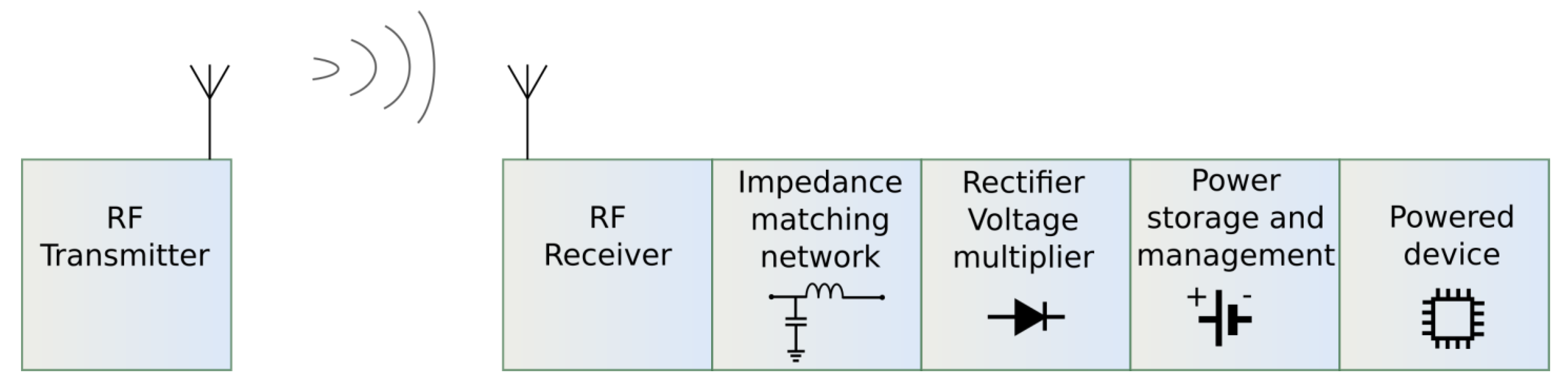
4.1. Rectenna for Wearable Applications

Early experiments with the transmission of significant amounts of energy via electromagnetic waves at radio frequencies are attributed to Nikola Tesla. His company built transmission towers and facilities for research into global communication systems. Having performed some initial experiments, Tesla claimed that he could transmit power wirelessly at a significant distance [65]. Tesla’s research into radio frequencies was hindered by fierce competition from Marconi, as well as his bankruptcy. Therefore, the real extent of the achievements of the famous visionary continues to be debated today. However, the use of radio waves to transmit energy became a reality over the next century [66].
Zhang et al. developed a low-power sensor chip in 130 nm technology requiring only 19 µW of power [67]. A key application of BAN devices based on this chip is to detect human physiological signals, such as ECG, EMG, and EEG. The boost converter ensures a proper power supply to the device, with a TEG as the main source of harvested energy. In their study, the authors observed that the converter requires a pre-charge voltage of not less than 600 mV to become active and begin providing the energy harvested regularly from the TEG. Thus, the device must be powered by an additional source of power before it can be utilized. To ensure that the BAN device remains small and requires minimal user intervention, the authors decided to use radio frequency energy harvesting rather than mechanical or battery-based components. To achieve that goal, the antenna is tuned to ISM 433 MHz and should receive a pulse signal of about −10 dBm for about 1–2 s. The rectifier that follows the antenna uses a 6-stage charge pump, which provides enough voltage for the TEG-connected converter to turn on and clamp the output voltage at 1.35 V, making the device fully operational.
In a setup developed by Yang et al., the device can harvest energy at frequencies typically associated with mobile phones, including 900 MHz, 2.025 GHz, and 2.36 GHz [68]. In this study, energy was harvested using a wearable multi-band patch antenna built on a RO4350 dielectric substrate designed for high-frequency applications. The investigated slot-ring antenna had dimensions of approximately 66 by 70 mm, which makes it suitable for use in BAN equipment. An antenna of this shape produces multi-mode resonances, which were observed in this setup both at expected frequencies and at 1.575 GHz. At 2.025 GHz, efficiency reached nearly 60% at 0 dBm input power. In their experiment, researchers supplied power to several development modules, including an MSP430F149 microcontroller and an NRF24L01 transceiver. However, their research was expected to have a wide range of applications, including battery-less and more compact biomedical devices.
One of the most commonly present radio signals in residential and office buildings is in the 2.4 GHz ISM band, mainly WiFi. Unsurprisingly, this band is used in IoT smart home systems, which rely on RF energy harvesting [69]. The size of the antenna typically used in IoT devices makes it challenging to apply a similar approach to BAN devices. Usually, it is a patch antenna on a dielectric substrate, which makes it thin but relatively large in other dimensions. With an edge over 100 mm, these cannot be considered wearable, thus rendering this approach hardly usable for BAN nodes. Antennas suitable for energy harvesting in the 2.4 GHz band with smaller dimensions are less common but exist.
In another study, a comparatively small patch rectenna was designed by Lin et al. for their mobile healthcare device [70]. It uses a single-stage full-wave Greinacher rectifier that resides on a substrate of 50.3 by 42.4 mm. The antenna occupies an area of 90 by 100 mm and has a thickness of 4.2 mm; therefore, it is too large for a wearable device. However, the antenna is woven into the user’s clothes, making it less intrusive. The voltage generated by this rectenna is up to 2.1 V at the proximity of the WiFi router. As might be expected, it drops exponentially with increasing distance, presenting as much as 0.3 V at a distance of 1.5 m from the router.
An example of a more compact antenna specified for 2.45 GHz is the one that was designed by Zhang et al. [71]. It uses a rectangular substrate with an edge length equal to 30 mm and as thin as 0.7 mm. There is, however, a dielectric resonator stacked with it, which has a height of 9 mm and a base edge length equal to 18 mm. Despite the SMA connector and slightly larger size, it is still a viable option for wearable BAN devices.
In the increasingly popular 5.8 GHz range of the WiFi spectrum, similar designs are being attempted as well. Nguyen et al. have designed a quadruple-patch antenna on a substrate that measures 85 mm × 85 mm [72]. The rectifier in this research used a matching network constructed of microstrip lines. The network provided S11 < 14 dB at the resonance frequency. The device also consisted of a voltage doubler composed of HSMS2860 Schottky diodes supported by a 10 uF capacitor and followed by a DC filter. Using 7 dBm input power, the authors achieved a conversion efficiency of 75%, and it was no less than 40% at 16 dBm.

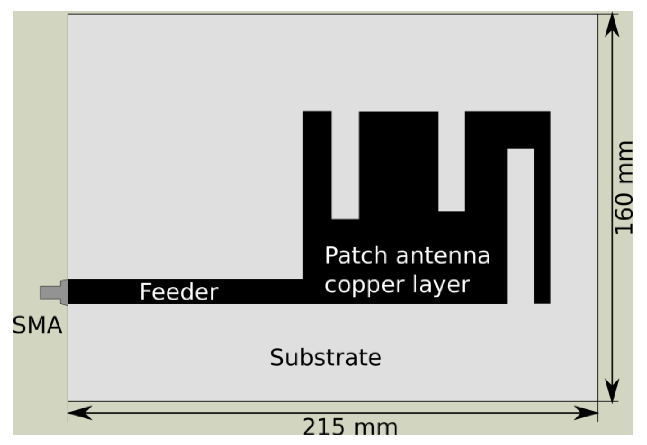
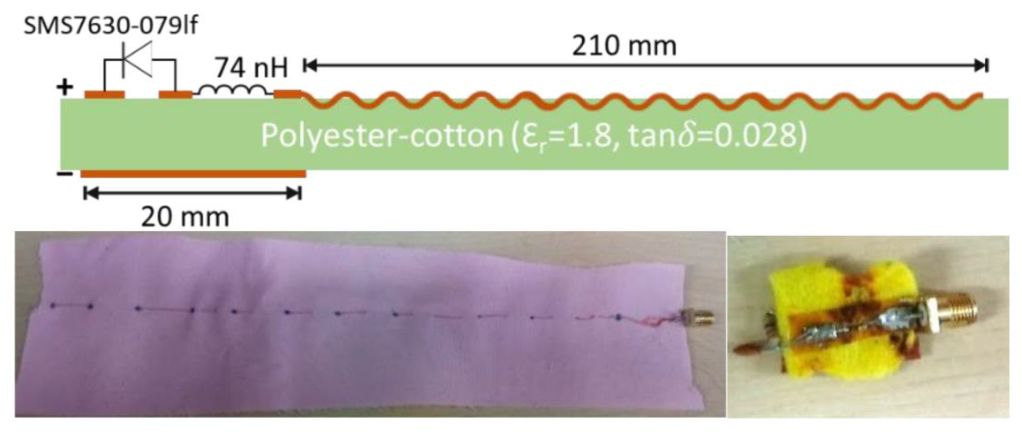
Textile-Based Rectenna

With the widespread adoption of GSM mobile technology, wearable electronics have emerged. In view of the fact that people are accustomed to wearing clothing, combining textiles with a patch antenna made of copper layers poses some challenges. Early work in this area was performed by Massey [73]. Yamada has reviewed textile-based rectennas in extensive detail, so only two examples that are not included in his work will be discussed below [74]. An exemplary textile-based rectenna is shown in Figure 14.
Using a textile-based antenna, Wagih and co-workers conducted research on simultaneously harvesting energy and transmitting information using a single-patch antenna [76]. By utilizing a laser cutter, the authors were able to produce shapes for the patch antenna out of conductive textile and apply them to two layers of felt. A multilayer structure was then formed by gluing together felt pieces. While the antenna operates at 2.4 GHz when it is employed for communication, it is capable of harvesting energy with a wide bandwidth in the sub-1 GHz range, mainly in the European ISM 868 MHz band. Even with as little as 0.1 µW/cm2, the device can produce 330 mVDC, which is sufficient to start the ultra-low-power boost converter BQ25504. Using this rectenna on the body has a peak efficiency of 63%, which is similar to other solutions. However, the compactness of the device is impressive. The antenna measures approximately 75 mm by 65 mm and is 3.2 mm thick. The voltage rectifier occupies not more than 3.5 mm by 8.5 mm. The device is therefore flexible and can be easily worn as an armband or stitched to other clothing.
Textile-based antennas for BAN applications are prone to stretching and wear. Some authors, such as in the research discussed above, prefer thick and solid fabric substrates, such as felt. In spite of this, Zhang and others acknowledge that fabrics are flexible, so the antennas attached to them should also be flexible [77]. Stretchable BAN devices may feel more natural on the skin for people wearing them. However, if the dimensions of the antenna change, resonance frequencies may be affected. Penn University researchers added asymmetric copper arches in order to design a 3D antenna that is less susceptible to varying resonance frequencies as a result of stretching. The rectenna operates in the 2.4 GHz band and is supported by a matching network and rectifier based on a SMS7630 Schottky diode. A supercapacitor is charged from 0 volts to 0.5 volts within 200 s and then provides a stable 1.8 V to electronic circuits. The experimental-setup-employed transmitter provided a −3 dBm signal at various distances up to 120 m from the receiver. Several types of 3D arched antenna were tested, showing a received power from −20 dBm in the proximity of the transmitter down to −90 dBm at 120 m. It has been shown by the authors of this research that their method can be applied to BAN devices to measure parameters, such as temperature, strain, and heart rate.
Comparison of RF energy harvesters is presented in Table 8.

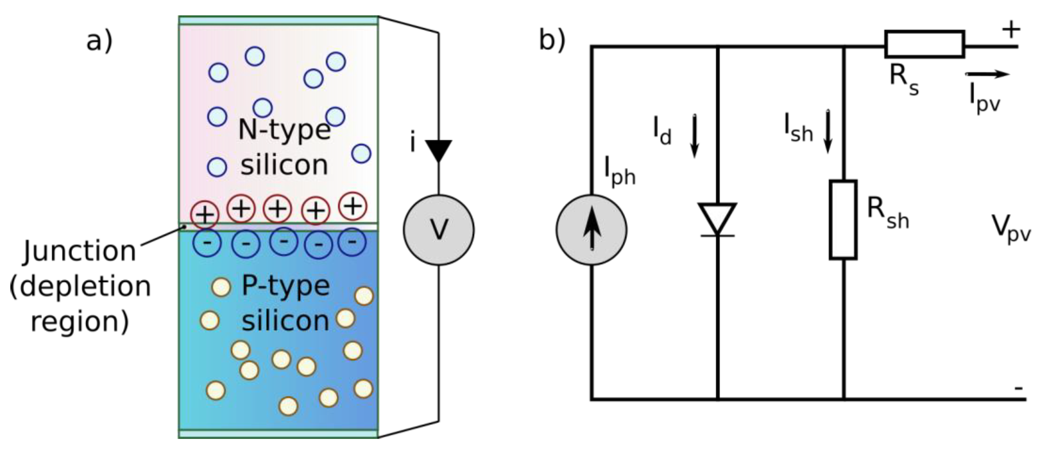
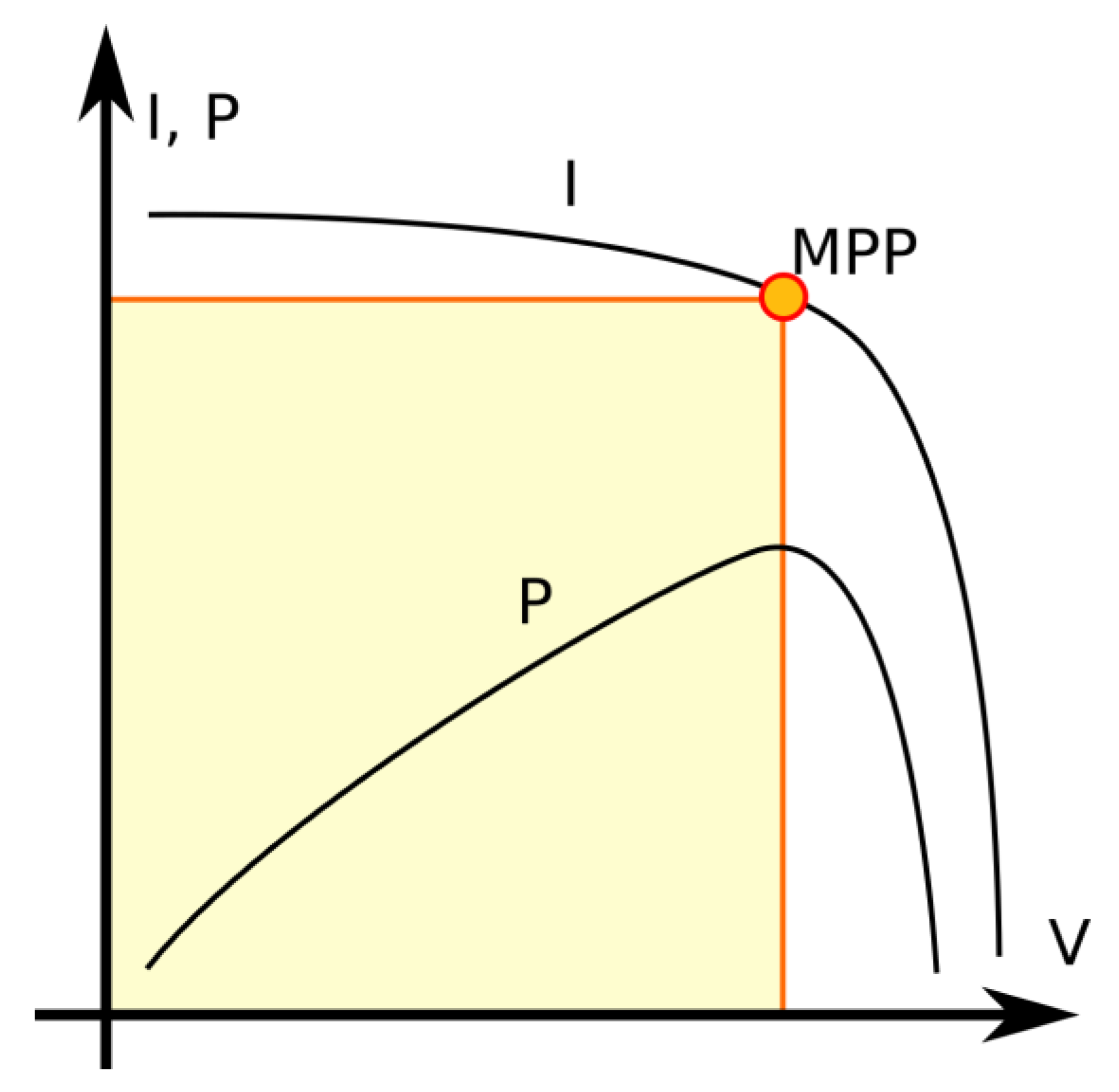
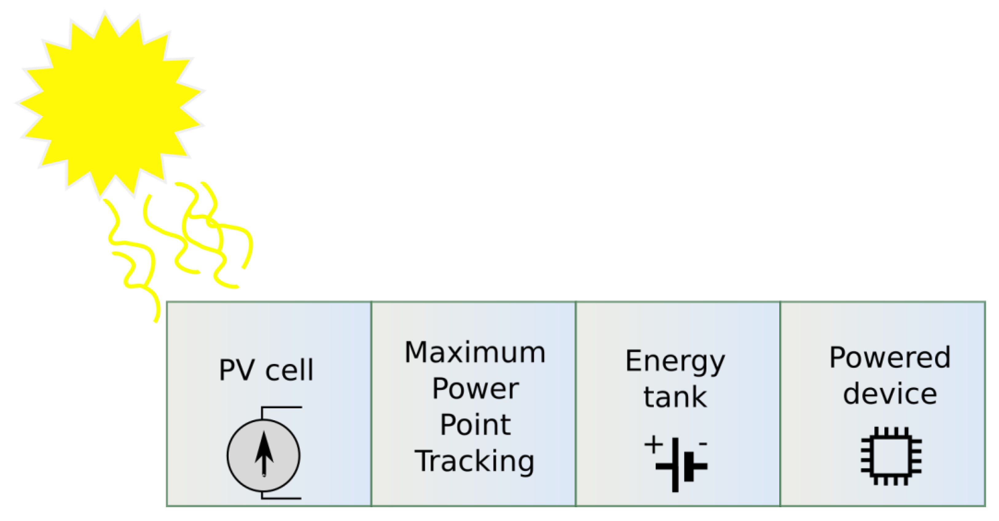
4.2. Photovoltaic Energy Harvesting for Wearables and Body Area Network

As photons are absorbed by material, they may excite electrons in this material. The electrons may leave the material by way of the photoelectric effect or may remain within its volume. The latter scenario leads to an uneven distribution of the electric field within the material, which may manifest as a potential difference between two points on it. If the difference value is large enough, there may be a voltage drop significant enough to generate current. This effect is referred to as photovoltaic and works best in a p–n junction, where excited electrons likely flow to the n side. Figure 15 shows the basic concept of a photovoltaic cell and its equivalent circuit.
From the figure above, an equation can be derived (8):
I pv = I ph I d I sh
here the photovoltaic current is I ph , but there is also energy loss due to the dark current I d and shunt resistor R sh .
The above equation expands to:
I pv = I ph I 0   e q V pv + I pv R s nkT 1   R s I pv + V pv R sh
In laboratory conditions, photovoltaic cells have efficiencies ranging from 10% for amorphous silicon to 25% for crystalline silicon and even up to 33% for two-junction GaAs. There is, however, an inverse relationship between efficiency and temperature, which poses a practical dilemma. It is possible to generate more energy under strong sunlight; however, infrared light adversely affects the efficiency of the photocells since it heats them. An increased drop in the output voltage of the cell indicates this loss of efficiency.
The most critical aspect of PV efficiency analysis is the I-V characteristic along with the power characteristic and its maximum power point (MPP). The general shape of these is shown in Figure 16. In order to maximize the efficiency of energy harvesting from solar cells, MPP tracking (MPPT) is used as a power management technique. This concept is illustrated in Figure 17, which depicts the block diagram of a PV energy harvester that utilizes this concept.
Advanced research by Chen et al. has led to the development of an extremely small sensor device based on solar cells [78]. A custom-crafted ARM-based MCU was mounted between the battery and solar cell in a sandwich-like structure. As a whole, the entire structure occupies approximately 8.75 mm3 of space. Because of the device’s small size, it can be used to measure intra-ocular pressure during glaucoma diagnosis. In an active state, it reads sensors and processes data consuming 7.7 µW or 28.9 pJ per instruction. However, it is essential to note that this device uses a 32-bit MCU based on ARM Cortex-M3 architecture, unlike other devices based on 8-bit MCUs. In an idle sleep mode, the device requires only 550 pW of power, resulting in a 5-year battery life without harvesting. The parameters above are impressive, but it is worth noting that the device is essentially a multilayered chip without a protective enclosure or any obvious means of attaching it to a body.
Solar panels based on silicon are typically rigid structures. Recent years have seen an increase in the availability of thin-film and flexible solutions based on inexpensive polymer substrates. Due to their ability to be sewn to clothing, they are only slightly obtrusive and therefore well suitable for use in BANs.
Wu et al. designed a wearable device using a flexible 7.2 by 6 cm PV panel that charges a 12.5 F supercapacitor energy tank using a buck-boost converter [79]. Additionally, there is a flexible PCB on the other side of the device that contains a voltage regulator, an MCU, and an accelerometer. This PCB also serves as a hub for other components of the device, such as a PV panel and other sensors. A rigid yet small Bluetooth low-energy (BLE) module based on the Texas Instruments CC2541 transceiver connects the device to a mobile phone. Figure 18 illustrates how the device can be worn as a wristband or attached to clothing.
Based on the placement of the device on the body, as well as the sensors that are being used, the device can measure the different biological parameters of an individual, such as temperature and heart rate. Additionally, it was designed as a fall detector with an accelerometer. It was programmed to wake up every 10 min, collect data, transmit it within a 14.5 s time span, and then go to sleep again. This results in a duty cycle less than 2.5% of the period and an average power consumption of 1053.6 mJ per cycle. However, it is worth noting that as much as 667.8 mJ is consumed during the brief active state. The authors calculated that their device can operate for about 17 h once fully charged, and 1 h spent outside is enough to charge it completely.
It is essential to note that bending PV panels reduces the efficiency of energy harvesting, since the light is irradiated at different angles. An increase in angle results in more photons being reflected from the surface, resulting in a reduction in PV cell output. This was investigated by Toh et al., who built wearable armband sensors for biomedical applications using flexible PV panels and circuit boards [80]. The authors tested their device in relatively low lighting levels, which are more typical of indoor situations. Interestingly, tracing the MPP is more critical than the angle at which the light is irradiated in such a case. The device consumed 39.162 µAs for a cycle of active operation, while the PV panel provided 180 µW. Despite tough conditions, the device was self-sustaining.
In the BAN, flexible PV panels and flexible circuit boards are widely known and used. There remains a problem with these types of harvesters in that they have a physically large and inflexible energy tank, such as a supercapacitor. Researchers from the University of California, Berkeley, have demonstrated the feasibility of enabling flexibility in lithium-ion batteries [81]. The wearable device that they have developed is shown in Figure 19.
A battery, a microcontroller, and an optoelectronic photoplethysmogram sensor were located under the PV module. The sensor detects blood flow within skin tissue that pulses at a heart rate. This battery had a capacity of approximately 50 mAh and was regularly, rapidly, and deeply discharged and charged in approximately 100 test cycles. The device was also bent 600 times during the testing process. Neither of these actions significantly affected the performance of the device. A total of 3.9 mA of current was provided by the PV cell for less than 60 min, which was sufficient to fully charge the battery to 4.1 V. Without recharging, the device operated for approximately 120 min.
An alternative approach to the problem of device size was taken by Jokic and Magno [82]. Their flexible bracelet looks similar to a wristwatch band and uses a typical buckle-and-tongue design. On the inner layer of the band, there is a CC2650 chip for Bluetooth low-energy (BLE) connectivity, an NFC module for accessing EEPROMs, an energy-harvesting circuit, and a lithium battery. The authors selected the DTP301120 battery, which has dimensions of 22 mm and 11 mm, but is only 3 mm tall. Despite its small size, the battery has a capacity of 40 mAh. Using the bracelet, 0.15 mW of power can be harvested indoors with an illumination of 500 lux. As much as 16.5 mW of power can be harvested outdoors with an illumination of over 10,000 lux. The idle mode lasted 55 s, or nearly 92 % of the cycle, and consumed 4.8 µW. During the active state with sensors and BLE data transmission turned on, power consumption increased to 648.6 µW. The data transmission was scheduled once per hour and was expected to last for 30 s. In accordance with the authors’ claims, their device could operate perpetually under these conditions and would require only about 1000 lux of constant illumination.
The process of sewing flexible PV panels to clothing would not be necessary in BAN wearable devices if the clothing itself could be used as a photo-sensitive energy harvester. Such alternatives include polymer or organic solar cells (OSC), dye-sensitized solar cells (DSSC), quantum-dot solar cells (QDSC), and perovskite solar cells (PSC). These materials were reviewed by Zhang et al. [83].
The application of PV cells as ink is possible with organic photovoltaic cells thanks to the fact that these are soluble. The construction of such a cell requires the application of several chemical layers on a substrate. In a paper published by Batista and others, glass was used as a substrate [84]. Despite of the rigid substrate, the cell was small, measuring only 12 mm on each edge, which makes it highly suitable for use in a BAN. Using an irradiating power density of 86.25 mW/cm2, the cell was able to produce over 1.2 mW at an MPP of 0.5 V. Based on the estimated conversion factor for solar light of 0.0079 W/m2/lux, it was about 110,000 lux or 0.8 of the sun’s irradiance. Therefore, a large amount of sunlight was necessary for the cell to function. However, even with an open circuit, the available voltage was less than 0.7 V, which is not sufficient for a typical CMOS circuit that operates in the range of 1.0–1.2 V. Hence, voltage doubling and power management were necessary. For that purpose, the PV cell was integrated with a power management LVCMOS chip. This modification allowed the device to provide 0.11 mA at 1.20 V when irradiated as discussed above. This would be able to power a simple sensor with adequate energy.
Comparison of photovoltaic energy harvesters is presented in Table 9.
For RF energy-harvesting BAN devices, the biggest challenge is the size of the antenna. It is necessary to make it small so that the device might be wearable without burdening the user. RF energy harvesting is advantageous in that it can be used regardless of body movement and temperature differences from the surrounding environment. Moreover, the rectenna might be concealed within clothing, making its presence almost imperceivable.
Photovoltaic panels for BAN are rarely rigid, silicon-based components. Instead, flexible sheets are commonly in use. However, this approach might soon become obsolete as the clothing itself may become a solar panel if it is properly coated or made of advanced fibers.

5. Conclusions

The trend of using energy-harvesting circuits to power WSN and IoT nodes is evident. Based on the above review, we can conclude that this trend is also evident in wearable sensors. The performance of EH-assisted energy-harvesting circuits can already power a BAN node equipped with standard sensors as its energy consumption (depending on the state of activity) at the level of a single mW or even hundreds of μW [85,86]. The use of energy harvesting allows for a significant extension of the operation of the node and even makes it energy self-sustainable.
Table 10 contains the comparison of the maximum output power density achieved independently in each group of harvesters. Additionally, the assessment of other utility factors was performed. The comparison resulted in the piezoelectric harvester as the best choice. Additionally authors decided to specify the durability and costs of particular groups of devices. One of the criterion is the mechanical movement presence in the principle of operation for the harvesters. That is why electromagnetic and triboelectric harvesters were considered as the least durable among others. The authors also tried to estimate the cost, i.e., the economic factor for the harvesters. All presented devices do not seem to be expensive as the total cost for each group estimates for tens of US dollars. In this case, piezoelectric and triboelectric harvesters are supposed to be more expensive, because the cost of the piezoelectric foils materials.
In the case of wearable sensors, the compactness of the harvester is a critical factor. Harvesters that achieve very high output powers but are not comfortable to use or are too large will not be applicable. In the case of kinetic energy conversion, there are low frequencies of vibrations that can be produced by humans. The upper frequency limit is 10 Hz. In contrast, the efficiency of both electromagnetic and piezoelectric systems depends on the frequency, which is usually located above the mentioned limit. RF harvesters, on the other hand, allow continuous energy production, but the power obtained is very low.
Despite the aforementioned problems, EH systems are becoming an indispensable component of wearable systems. In addition to the hybridization of the solution involving the simultaneous reproduction of several forms of energy or the use of different transducers for the same energy (e.g., piezoelectric and triboelectric harvesters [51,52]), the use of new materials increases the efficiency of energy conversion, allowing us to obtain satisfactory results.

Author Contributions

Conceptualization, B.D.; methodology, B.D., Ł.M. and M.K.; formal analysis, B.D., Ł.M., M.K. and A.J.; writing—original draft preparation, B.D., Ł.M. and M.K.; writing—review and editing, B.D., Ł.M., M.K. and A.J. All authors have read and agreed to the published version of the manuscript.

Funding

This research received no external funding.

Institutional Review Board Statement

Not applicable.

Informed Consent Statement

Not applicable.

Data Availability Statement

Not applicable.

Conflicts of Interest

The authors declare no conflict of interest.

References

  1. Tesla, N. Experiments with alternate currents of high potential and high frequency. J. Inst. Electr. Eng. 1892, 21, 51–162. [Google Scholar] [CrossRef]
  2. Aabid, A.; Raheman, M.A.; Ibrahim, Y.E.; Anjum, A.; Hrairi, M.; Parveez, B.; Parveen, N.; Zayan, J.M. A Systematic Review of Piezoelectric Materials and Energy Harvesters for Industrial Applications. Sensors 2021, 21, 4145. [Google Scholar] [CrossRef] [PubMed]
  3. Ando Junior, O.H.; Maran, A.L.O.; Henao, N.C. A Review of the Development and Applications of Thermoelectric Microgenerators for Energy Harvesting. Renew. Sustain. Energy Rev. 2018, 91, 376–393. [Google Scholar] [CrossRef]
  4. Kanoun, O.; Khriji, S.; Naifar, S.; Bradai, S.; Bouattour, G.; Bouhamed, A.; El Houssaini, D.; Viehweger, C. Prospects of Wireless Energy-Aware Sensors for Smart Factories in the Industry 4.0 Era. Electronics 2021, 10, 2929. [Google Scholar] [CrossRef]
  5. Wang, H.; Jasim, A.; Chen, X. Energy Harvesting Technologies in Roadway and Bridge for Different Applications—A Comprehensive Review. Appl. Energy 2018, 212, 1083–1094. [Google Scholar] [CrossRef]
  6. Park, G.; Rosing, T.; Todd, M.D.; Farrar, C.R.; Hodgkiss, W. Energy Harvesting for Structural Health Monitoring Sensor Networks. J. Infrastruct. Syst. 2008, 14, 64–79. [Google Scholar] [CrossRef]
  7. Zou, Y.; Sun, M.; Xu, W.; Zhao, X.; Du, T.; Sun, P.; Xu, M. Advances in Marine Self-Powered Vibration Sensor Based on Triboelectric Nanogenerator. J. Mar. Sci. Eng. 2022, 10, 1348. [Google Scholar] [CrossRef]
  8. Salehi, H.; Burgueño, R.; Chakrabartty, S.; Lajnef, N.; Alavi, A.H. A Comprehensive Review of Self-Powered Sensors in Civil Infrastructure: State-of-the-Art and Future Research Trends. Eng. Struct. 2021, 234, 111963. [Google Scholar] [CrossRef]
  9. Chen, H.; Xing, C.; Li, Y.; Wang, J.; Xu, Y. Triboelectric Nanogenerators for a Macro-Scale Blue Energy Harvesting and Self-Powered Marine Environmental Monitoring System. Sustain. Energy Fuels 2020, 4, 1063–1077. [Google Scholar] [CrossRef]
  10. Ganiyu, S.O.; Martínez-Huitle, C.A. The Use of Renewable Energies Driving Electrochemical Technologies for Environmental Applications. Curr. Opin. Electrochem. 2020, 22, 211–220. [Google Scholar] [CrossRef]
  11. Dziadak, B.; Makowski, Ł.; Michalski, A. Survey of Energy Harvesting Systems for Wireless Sensor Networks in Environmental Monitoring. Metrol. Meas. Syst. 2016, 23, 495–512. [Google Scholar]
  12. Mamun, M.A.A.; Yuce, M.R. Sensors and Systems for Wearable Environmental Monitoring Toward IoT-Enabled Applications: A Review. IEEE Sens. J. 2019, 19, 7771–7788. [Google Scholar] [CrossRef]
  13. Zhao, L.; Li, H.; Meng, J.; Li, Z. The Recent Advances in Self-Powered Medical Information Sensors. InfoMat 2020, 2, 212–234. [Google Scholar] [CrossRef]
  14. Zheng, Q.; Tang, Q.; Wang, Z.L.; Li, Z. Self-Powered Cardiovascular Electronic Devices and Systems. Nat. Rev. Cardiol. 2021, 18, 7–21. [Google Scholar] [CrossRef] [PubMed]
  15. Jiang, D.; Shi, B.; Ouyang, H.; Fan, Y.; Wang, Z.L.; Li, Z. Emerging Implantable Energy Harvesters and Self-Powered Implantable Medical Electronics. ACS Nano 2020, 14, 6436–6448. [Google Scholar] [CrossRef] [PubMed]
  16. Kleiber, M. Body Size and Metabolic Rate. Physiol. Rev. 1947, 27, 511–541. [Google Scholar] [CrossRef] [PubMed]
  17. Keler, J.S. Human Energy Balance; SGGW: Warsaw, Poland, 2017. (In Polish) [Google Scholar]
  18. Keller, J.S. Maintenance Energy Requirements in Adult and Growing Organisms—An Unresolved Problem. J. Anim. Feed Sci. 2002, 11, 351–366. [Google Scholar] [CrossRef]
  19. Włodarek, D.; Lange, E.; Kozłowska, L.; Głąbska, D. Dietoterapia 1. Zapotrzebowanie Energetyczne Organizmu Człowieka; Państwowe Zakłady Wydawnictw Lekarskich: Warsaw, Poland, 2014. [Google Scholar]
  20. Frappier, J.; Toupin, I.; Levy, J.J.; Aubertin-Leheudre, M.; Karelis, A.D. Energy Expenditure during Sexual Activity in Young Healthy Couples. PLoS ONE 2013, 8, e79342. [Google Scholar] [CrossRef]
  21. Piñuela, M.; Mitcheson, P.D.; Lucyszyn, S. Ambient RF Energy Harvesting in Urban and Semi-Urban Environments. IEEE Trans. Microw. Theory Tech. 2013, 61, 2715–2726. [Google Scholar] [CrossRef]
  22. Covaci, C.; Gontean, A. Piezoelectric Energy Harvesting Solutions: A Review. Sensors 2020, 20, 3512. [Google Scholar] [CrossRef]
  23. Caliò, R.; Rongala, U.B.; Camboni, D.; Milazzo, M.; Stefanini, C.; De Petris, G.; Oddo, C.M. Piezoelectric Energy Harvesting Solutions. Sensors 2014, 14, 4755–4790. [Google Scholar] [CrossRef] [PubMed] [Green Version]
  24. Hyland, M.; Hunter, H.; Liu, J.; Veety, E.; Vashaee, D. Wearable Thermoelectric Generators for Human Body Heat Harvesting. Appl. Energy 2016, 182, 518–524. [Google Scholar] [CrossRef]
  25. Song, H.; Huang, X.; Jiang, X.; Wang, J. The synchronized switch harvesting circuit on inductor based on piezoelectricity. In Proceedings of the 2011 International Conference on Consumer Electronics, Communications and Networks (CECNet), Xianning, China, 16–18 April 2011. [Google Scholar] [CrossRef]
  26. Lallart, M.; Richard, C.; Li, Y.; Wu, Y.; Guyomar, D. Load-Tolerant, High-Efficiency Self-Powered Energy Harvesting Scheme Using a Nonlinear Approach. Energy Harvest. Syst. 2014, 1, 197–208. [Google Scholar] [CrossRef]
  27. Tri Nguyen, H.; Genov, D.A.; Bardaweel, H. Vibration Energy Harvesting Using Magnetic Spring Based Nonlinear Oscillators: Design Strategies and Insights. Appl. Energy 2020, 269, 115102. [Google Scholar] [CrossRef]
  28. Gao, M.; Wang, Y.; Wang, Y.; Wang, P. Experimental Investigation of Non-Linear Multi-Stable Electromagnetic-Induction Energy Harvesting Mechanism by Magnetic Levitation Oscillation. Appl. Energy 2018, 220, 856–875. [Google Scholar] [CrossRef]
  29. Zhang, Q.; Wang, Y.; Kim, E.S. Electromagnetic Energy Harvester With Flexible Coils and Magnetic Spring for 1–10 Hz Resonance. J. Microelectromech. Syst. 2015, 24, 1193–1206. [Google Scholar] [CrossRef]
  30. Wu, S.; Luk, P.C.K.; Li, C.; Zhao, X.; Jiao, Z. Investigation of an Electromagnetic Wearable Resonance Kinetic Energy Harvester With Ferrofluid. IEEE Trans. Magn. 2017, 53, 4600706. [Google Scholar] [CrossRef]
  31. Li, C.; Wu, S.; Luk, P.C.K.; Gu, M.; Jiao, Z. Enhanced Bandwidth Nonlinear Resonance Electromagnetic Human Motion Energy Harvester Using Magnetic Springs and Ferrofluid. IEEE/ASME Trans. Mechatron. 2019, 24, 710–717. [Google Scholar] [CrossRef]
  32. Samad, F.A.; Karim, M.F.; Paulose, V.; Ong, L.C. A Curved Electromagnetic Energy Harvesting System for Wearable Electronics. IEEE Sens. J. 2016, 16, 1969–1974. [Google Scholar] [CrossRef]
  33. Mitura, A.; Kecik, K. Modeling and Energy Recovery from a System with Two Pseudo-Levitating Magnets. Bull. Pol. Acad. Sci. Tech. Sci. 2022, 70, e141721. [Google Scholar]
  34. Fu, H.; Theodossiades, S.; Gunn, B.; Abdallah, I.; Chatzi, E. Ultra-Low Frequency Energy Harvesting Using Bi-Stability and Rotary-Translational Motion in a Magnet-Tethered Oscillator. Nonlinear Dyn. 2020, 101, 2131–2143. [Google Scholar] [CrossRef]
  35. Li, M.; Deng, H.; Zhang, Y.; Li, K.; Huang, S.; Liu, X. Ultra-Low Frequency Eccentric Pendulum-Based Electromagnetic Vibrational Energy Harvester. Micromachines 2020, 11, 1009. [Google Scholar] [CrossRef] [PubMed]
  36. Halim, M.A.; Rantz, R.; Zhang, Q.; Gu, L.; Yang, K.; Roundy, S. Modeling and Experimental Analysis of a Wearable Energy Harvester That Exploits Human-Body Motion. In Proceedings of the 2018 IEEE SENSORS, New Delhi, India, 28–31 October 2018; pp. 1–4. [Google Scholar]
  37. Lin, J.; Liu, H.; Chen, T.; Yang, Z.; Sun, L. A Rotational Wearable Energy Harvester for Human Motion. In Proceedings of the 2017 IEEE 17th International Conference on Nanotechnology (IEEE-NANO), Pittsburgh, PA, USA, 25–28 July 2017; pp. 22–25. [Google Scholar]
  38. Xue, T.; Williams, S.; Rantz, R.; Halim, M.A.; Roundy, S. System Modeling, Characterization, and Design Considerations for Generators in Commercial Watches With Application to Energy Harvesting for Wearables. IEEE/ASME Trans. Mechatron. 2018, 23, 2515–2524. [Google Scholar] [CrossRef]
  39. Magno, M.; Kneubühler, D.; Mayer, P.; Benini, L. Micro Kinetic Energy Harvesting for Autonomous Wearable Devices. In Proceedings of the 2018 International Symposium on Power Electronics, Electrical Drives, Automation and Motion (SPEEDAM), Amalfi, Italy, 20–22 June 2018; pp. 105–110. [Google Scholar]
  40. Wang, Y.; Zhang, Q.; Zhao, L.; Kim, E.S. Non-Resonant Electromagnetic Broad-Band Vibration-Energy Harvester Based on Self-Assembled Ferrofluid Liquid Bearing. J. Microelectromech. Syst. 2017, 26, 809–819. [Google Scholar] [CrossRef]
  41. Bao, C.; Luo, A.; Zhuang, Y.; Huang, J.; Wang, F. A Wearable Health Monitoring System Self-Powered by Human-Motion Energy Harvester. In Proceedings of the 2021 IEEE 16th International Conference on Nano/Micro Engineered and Molecular Systems (NEMS), Xiamen, China, 25–29 April 2021; pp. 990–993. [Google Scholar]
  42. Kawa, B.; Lee, C.; Walczak, R. Inkjet 3D Printed MEMS Electromagnetic Multi-Frequency Energy Harvester. Energies 2022, 15, 4468. [Google Scholar] [CrossRef]
  43. Yu, H.; Zhou, J.; Deng, L.; Wen, Z. A Vibration-Based MEMS Piezoelectric Energy Harvester and Power Conditioning Circuit. Sensors 2014, 14, 3323–3341. [Google Scholar] [CrossRef] [PubMed]
  44. Turkmen, A.C.; Celik, C. Energy Harvesting with the Piezoelectric Material Integrated Shoe. Energy 2018, 150, 556–564. [Google Scholar] [CrossRef]
  45. Iqbal, M.; Khan, F.U.; Mehdi, M.; Cheok, Q.; Abas, E.; Nauman, M.M. Power Harvesting Footwear Based on Piezo-Electromagnetic Hybrid Generator for Sustainable Wearable Microelectronics. J. King Saud Univ. Eng. Sci. 2022, 34, 329–338. [Google Scholar] [CrossRef]
  46. Jiang, X.-Y.; Zou, H.-X.; Zhang, W.-M. Design and Analysis of a Multi-Step Piezoelectric Energy Harvester Using Buckled Beam Driven by Magnetic Excitation. Energy Convers. Manag. 2017, 145, 129–137. [Google Scholar] [CrossRef]
  47. Wei, S.; Hu, H.; He, S. Modeling and Experimental Investigation of an Impact-Driven Piezoelectric Energy Harvester from Human Motion. Smart Mater. Struct. 2013, 22, 105020. [Google Scholar] [CrossRef]
  48. Pillatsch, P.; Yeatman, E.M.; Holmes, A.S. A Piezoelectric Frequency Up-Converting Energy Harvester with Rotating Proof Mass for Human Body Applications. Sens. Actuators A Phys. 2014, 206, 178–185. [Google Scholar] [CrossRef]
  49. Hwang, G.-T.; Park, H.; Lee, J.-H.; Oh, S.; Park, K.-I.; Byun, M.; Park, H.; Ahn, G.; Jeong, C.K.; No, K.; et al. Self-Powered Cardiac Pacemaker Enabled by Flexible Single Crystalline PMN-PT Piezoelectric Energy Harvester. Adv. Mater. 2014, 26, 4880–4887. [Google Scholar] [CrossRef] [PubMed]
  50. Qian, F.; Xu, T.-B.; Zuo, L. Piezoelectric Energy Harvesting from Human Walking Using a Two-Stage Amplification Mechanism. Energy 2019, 189, 116140. [Google Scholar] [CrossRef]
  51. Li, Y.; Chen, Z.; Zheng, G.; Zhong, W.; Jiang, L.; Yang, Y.; Jiang, L.; Chen, Y.; Wong, C.-P. A Magnetized Microneedle-Array Based Flexible Triboelectric-Electromagnetic Hybrid Generator for Human Motion Monitoring. Nano Energy 2020, 69, 104415. [Google Scholar] [CrossRef]
  52. Hou, X.; Zhong, J.; Yang, C.; Yang, Y.; He, J.; Mu, J.; Geng, W.; Chou, X. A High-Performance, Single-Electrode and Stretchable Piezo-Triboelectric Hybrid Patch for Omnidirectional Biomechanical Energy Harvesting and Motion Monitoring. J. Mater. 2022, 8, 958–966. [Google Scholar] [CrossRef]
  53. Luo, X.; Zhu, L.; Wang, Y.-C.; Li, J.; Nie, J.; Wang, Z.L. A Flexible Multifunctional Triboelectric Nanogenerator Based on MXene/PVA Hydrogel. Adv. Funct. Mater. 2021, 31, 2104928. [Google Scholar] [CrossRef]
  54. Wu, Y.; Luo, Y.; Qu, J.; Daoud, W.A.; Qi, T. Sustainable and Shape-Adaptable Liquid Single-Electrode Triboelectric Nanogenerator for Biomechanical Energy Harvesting. Nano Energy 2020, 75, 105027. [Google Scholar] [CrossRef]
  55. Bai, Z.; Xu, Y.; Lee, C.; Guo, J. Autonomously Adhesive, Stretchable, and Transparent Solid-State Polyionic Triboelectric Patch for Wearable Power Source and Tactile Sensor. Adv. Funct. Mater. 2021, 31, 2104365. [Google Scholar] [CrossRef]
  56. Wu, Y.; Qu, J.; Zhang, X.; AO, K.; Zhou, Z.; Zheng, Z.; Mu, Y.; Wu, X.; Luo, Y.; Feng, S.-P. Biomechanical Energy Harvesters Based on Ionic Conductive Organohydrogels via the Hofmeister Effect and Electrostatic Interaction. ACS Nano 2021, 15, 13427–13435. [Google Scholar] [CrossRef]
  57. Zhu, G.; Bai, P.; Chen, J.; Wang, Z.L. Power-Generating Shoe Insole Based on Triboelectric Nanogenerators for Self-Powered Consumer Electronics. Nano Energy 2013, 2, 688–692. [Google Scholar] [CrossRef]
  58. Lossec, M.; Multon, B.; Ben Ahmed, H.; Goupil, C. Thermoelectric Generator Placed on the Human Body: System Modeling and Energy Conversion Improvements. Eur. Phys. J. Appl. Phys. 2010, 52, 11103. [Google Scholar] [CrossRef] [Green Version]
  59. Na, Y.; Kim, S.; Mallem, S.P.R.; Yi, S.; Kim, K.T.; Park, K.-I. Energy Harvesting from Human Body Heat Using Highly Flexible Thermoelectric Generator Based on Bi2Te3 Particles and Polymer Composite. J. Alloys Compd. 2022, 924, 166575. [Google Scholar] [CrossRef]
  60. Liu, H.; Wang, Y.; Mei, D.; Shi, Y.; Chen, Z. Design of a Wearable Thermoelectric Generator for Harvesting Human Body Energy. In Wearable Sensors and Robots: Proceedings of International Conference on Wearable Sensors and Robots 2015; Springer: Singapore, 2017; pp. 55–66. [Google Scholar] [CrossRef]
  61. Proto, A.; Bibbo, D.; Cerny, M.; Vala, D.; Kasik, V.; Peter, L.; Conforto, S.; Schmid, M.; Penhaker, M. Thermal Energy Harvesting on the Bodily Surfaces of Arms and Legs through a Wearable Thermo-Electric Generator. Sensors 2018, 18, 1927. [Google Scholar] [CrossRef] [PubMed]
  62. He, X.; Shi, J.; Hao, Y.; He, M.; Cai, J.; Qin, X.; Wang, L.; Yu, J. Highly Stretchable, Durable, and Breathable Thermoelectric Fabrics for Human Body Energy Harvesting and Sensing. Carbon Energy 2022, 4, 621–632. [Google Scholar] [CrossRef]
  63. Wang, Y.; Shi, Y.; Mei, D.; Chen, Z. Wearable Thermoelectric Generator to Harvest Body Heat for Powering a Miniaturized Accelerometer. Appl. Energy 2018, 215, 690–698. [Google Scholar] [CrossRef]
  64. Boursianis, A.D.; Papadopoulou, M.S.; Koulouridis, S.; Rocca, P.; Georgiadis, A.; Tentzeris, M.M.; Goudos, S.K. Triple-Band Single-Layer Rectenna for Outdoor RF Energy Harvesting Applications. Sensors 2021, 21, 3460. [Google Scholar] [CrossRef]
  65. Tesla, N. The Problem of Increasing Human Energy with Special Reference to the Harnessing of the Sun’s Energy. Century Illustrated Magazine, June 1900; 175–211. [Google Scholar]
  66. Brown, W.C. Experiments Involving a Microwave Beam to Power and Position a Helicopter. IEEE Trans. Aerosp. Electron. Syst. 1969, AES-5, 692–702. [Google Scholar] [CrossRef]
  67. Zhang, F.; Zhang, Y.; Silver, J.; Shakhsheer, Y.; Nagaraju, M.; Klinefelter, A.; Pandey, J.; Boley, J.; Carlson, E.; Shrivastava, A.; et al. A batteryless 19μW MICS/ISM-band energy harvesting body area sensor node SoC. In Proceedings of the 2012 IEEE International Solid-State Circuits Conference, San Francisco, CA, USA, 19–23 February 2012; pp. 298–300. [Google Scholar] [CrossRef]
  68. Yang, L.; Zhou, Y.J.; Zhang, C.; Yang, X.M.; Yang, X.X.; Tan, C. Compact Multiband Wireless Energy Harvesting Based Battery-Free Body Area Networks Sensor for Mobile Healthcare. IEEE J. Electromagn. RF Microw. Med. Biol. 2018, 2, 109–115. [Google Scholar] [CrossRef]
  69. Eltresy, N.A.; Dardeer, O.M.; Al-Habal, A.; Elhariri, E.; Abotaleb, A.M.; Elsheakh, D.N.; Khattab, A.; Taie, S.A.; Mostafa, H.; Elsadek, H.A.; et al. Smart Home IoT System by Using RF Energy Harvesting. J. Sens. 2020, 2020, 8828479. [Google Scholar] [CrossRef]
  70. Lin, C.H.; Chiu, C.W.; Gong, J.Y. A Wearable Rectenna to Harvest Low-Power RF Energy for Wireless Healthcare Applications. In Proceedings of the 2018 11th International Congress on Image and Signal Processing, BioMedical Engineering and Informatics (CISP-BMEI), Beijing, China, 13–15 October 2018; pp. 1–5. [Google Scholar] [CrossRef]
  71. Zhang, B.H.; Zhang, J.W.; Wu, Z.P.; Liu, C.G.; Zhang, B. A 2.45 GHz dielectric resonator rectenna for wireless power transmission. In Proceedings of the 2017 Sixth Asia-Pacific Conference on Antennas and Propagation (APCAP), Xi’an, China, 16–19 October 2017; pp. 1–3. [Google Scholar] [CrossRef]
  72. Nguyen, D.; Le Nguyen, H.; Seo, C. An 5.8 GHz Cube-Shape Energy Harvesting System Based on PIN Antenna Arrays. In Proceedings of the 2020 IEEE Wireless Power Transfer Conference (WPTC), Seoul, Republic of Korea, 15–19 November 2020; pp. 201–204. [Google Scholar] [CrossRef]
  73. Massey, P.J. Mobile phone fabric antennas integrated within clothing. In Proceedings of the 2001 Eleventh International Conference on Antennas and Propagation, (IEE Conf. Publ. No. 480), Manchester, UK, 17–20 April 2001; Volume 1, pp. 344–347. [Google Scholar] [CrossRef]
  74. Yamada, Y. Textile Materials for Wireless Energy Harvesting. Electron. Mater. 2022, 3, 26. [Google Scholar] [CrossRef]
  75. Wagih, M.; Weddell, A.S.; Beeby, S. Powering E-Textiles Using a Single Thread Radio Frequency Energy Harvesting Rectenna. Proceedings 2021, 68, 16. [Google Scholar] [CrossRef]
  76. Wagih, M.; Hilton, G.S.; Weddell, A.S.; Beeby, S. Dual-Band Dual-Mode Textile Antenna/Rectenna for Simultaneous Wireless Information and Power Transfer (SWIPT). IEEE Trans. Antennas Propag. 2021, 69, 6322–6332. [Google Scholar] [CrossRef]
  77. Zhang, S.; Zhu, J.; Zhang, Y.; Chen, Z.; Song, C.; Li, J.; Yi, N.; Qiu, D.; Guo, K.; Zhang, C.; et al. Standalone stretchable RF systems based on asymmetric 3D microstrip antennas with on-body wireless communication and energy harvesting. Nano Energy 2022, 96, 107069. [Google Scholar] [CrossRef]
  78. Chen, G.; Fojtik, M.; Kim, D.; Fick, D.; Park, J.; Seok, M.; Chen, M.T.; Foo, Z.; Sylvester, D.; Blaauw, D. Millimeter-scale nearly perpetual sensor system with stacked battery and solar cells. In Proceedings of the 2010 IEEE International Solid-State Circuits Conference—(ISSCC), San Francisco, CA, USA, 7–11 February 2010; pp. 288–289. [Google Scholar] [CrossRef]
  79. Wu, T.; Wu, F.; Redouté, J.-M.; Yuce, M.R. An Autonomous Wireless Body Area Network Implementation Towards IoT Connected Healthcare Applications. IEEE Access 2017, 5, 11413–11422. [Google Scholar] [CrossRef]
  80. Toh, W.Y.; Tan, Y.K.; Koh, W.S.; Siek, L. Autonomous Wearable Sensor Nodes With Flexible Energy Harvesting. IEEE Sensors J. 2014, 14, 2299–2306. [Google Scholar] [CrossRef]
  81. Ostfeld, A.E.; Gaikwad, A.M.; Khan, Y.; Arias, A.C. High-performance flexible energy storage and harvesting system for wearable electronics. Sci. Rep. 2016, 6, 26122. [Google Scholar] [CrossRef]
  82. Jokic, P.; Magno, M. Powering smart wearable systems with flexible solar energy harvesting. In Proceedings of the 2017 IEEE International Symposium on Circuits and Systems (ISCAS), Baltimore, MD, USA, 28–31 May 2017; pp. 1–4. [Google Scholar] [CrossRef]
  83. Zhang, Y.; Zhou, J.; Zhang, Y.; Zhang, D.; Yong, K.T.; Xiong, J. Elastic Fibers/Fabrics for Wearables and Bioelectronics. Adv. Sci. 2022, 9, 2203808. [Google Scholar] [CrossRef]
  84. Batista, D.; Oliveira, L.B.; Paulino, N.; Carvalho, C.; Oliveira, J.P.; Farinhas, J.; Charas, A.; dos Santos, P.M. Combined Organic Photovoltaic Cells and Ultra Low Power CMOS Circuit for Indoor Light Energy Harvesting. Sensors 2019, 19, 1803. [Google Scholar] [CrossRef]
  85. Dziadak, B.; Makowski, Ł.; Michalski, A. Konstrukcja węzła bezprzewodowej sieci czujnikowej wykorzystującego Energy Harvesting. Przegląd Elektrotechniczny 2016, 1, 65–68. [Google Scholar] [CrossRef]
  86. Gljušćić, P.; Zelenika, S.; Blažević, D.; Kamenar, E. Kinetic Energy Harvesting for Wearable Medical Sensors. Sensors 2019, 19, 4922. [Google Scholar] [CrossRef] [Green Version]
Figure 1. Average heat power (W) given off by a human as a function of mass.
Energies 16 01681 g001
Figure 2. Rectifier for energy harvester. On the left—linear rectifier. On the right—nonlinear rectifier.
Energies 16 01681 g002
Figure 3. Structure of linear electromagnetic energy harvester.
Energies 16 01681 g003
Figure 4. Structure design of a low-frequency vibration energy harvester: (a) assembly diagram of an energy harvester; (b) explosive view of an energy harvester; (c) magnetic field configuration for the eccentric rotor; (d) framework diagram of the finite element analysis (FEA) model ([35] CCBY).
Energies 16 01681 g004
Figure 5. Computer visualization of the harvester with two independent vibrating structures with magnets (scale bar 10 mm). Source of figure ([42] CCBY).
Energies 16 01681 g005
Figure 6. Principle of operation piezoelectric harvesters.
Energies 16 01681 g006
Figure 7. Principle of operation of the rotational beam-plucking energy harvester ([48] license number: 5443011255680).
Energies 16 01681 g007
Figure 8. Principle of operation for triboelectric harvesters.
Energies 16 01681 g008
Figure 9. Structural design of an energy-generating shoe insert based on flexible TENGs. (a) Photo of an energy-generating shoe insert. (b) Photograph of the internal structure of the insert. The scale bar is 2 cm. (c) Photograph of the internal structure of the insert. (d) Structure of multilayered elastic TENG. The zig-zag structure of the substrate accommodates three layers in one TENG. (e) SEM image of nanopores formed on the surface of aluminum foils. The scale bar is 200 nm ([57] license number 5443011421697).
Energies 16 01681 g009
Figure 10. Construction of the Peltier cell.
Energies 16 01681 g010
Figure 11. Schematic view of (a) TEG worn on the wrist to power the motion-monitoring sensor, (b) TEG construction, (c) cross-sections and structural parameters A-A’ and B-B’ ([63] license number: 5443011504464).
Energies 16 01681 g011
Figure 12. Block diagram of RF energy-harvesting system.
Energies 16 01681 g012
Figure 13. Shape of copper plane in sample rectenna; redrawn from [64].
Energies 16 01681 g013
Figure 14. Textile-based rectenna; source: [75] (CC BY).
Energies 16 01681 g014
Figure 15. (a) Photovoltaic cell working principle; (b) PV-cell-equivalent circuit.
Energies 16 01681 g015
Figure 16. I-V and P-V characteristics of PV cell with MPP marked.
Energies 16 01681 g016
Figure 17. Block diagram of PV-based EH system.
Energies 16 01681 g017
Figure 18. Wearable sensor with solar energy harvesting; source: [79] (license: CC).
Energies 16 01681 g018
Figure 19. Flexible PV panel, circuit board, and lithium battery [81] (license: CC BY 4.0).
Energies 16 01681 g019
Table 1. Energy expenditure for metabolic processes according to lifestyle (person weight 80 kg).
ProcessOffice WorkActive Work
Metabolic energy intake12.4 MJ100%16.1 MJ100%
Basal metabolism7.8 MJ63%7.8 MJ48.4%
Food-induced thermogenesis1.9 MJ15%2.4 MJ15%
Physical activity2.7 MJ~22%5.9 MJ~36.6%
Table 2. Metabolic Equivalent of Task for different activities.
ActivityCalorific Values [kcal/min]Metabolic Equivalent of Task [MET]
Reading0.4<1
Driving 0.8<1
Walking (3.2 km)3.12.5
Cycling (slow)4.43.5
Swimming (slow)5.64.5
Walking (6.4 km)5.64.5
Playing tennis 6.35
Cycling (fast)7.15.7
Sex (female)7.05.6
Sex (male)7.56
Swimming (fast)8.87
Rowing 1310.6
Running (14 km/h)15.912.7
Running sprint (~30 km/h)38.330.6
Table 3. Harvesting energy from the human body.
Form of EnergyPlace
of Installation
Electric Power Achievable after ConversionType of Harvester
HeatSkin5–18 μW/cm2Thermoelectric-generator
HeatInternal tissues12 μW/cm3Thermoelectric-generator
KineticBending fingers1 mWPiezoelectric
KineticThe work of hands3–100 mWPiezoelectric
Magnetoelectric
Triboelectric
KineticThe work of legs1–200 mWPiezoelectric
Magnetoelectric
Triboelectric
Table 4. Comparison electromagnetic harvesters.
TypeFormPlace of Installation VibrationPower[Ref]
LinearMatrix of 16 harvesterAnkle2.8 m/s14.8 mW[29]
Linear1 magnet with ferrofluid/2 coilsAnkle2.8 m/s9.5 mW[30]
Linear4 magnets stack with ferrofluid/3 coilsAnkle2.8 m/s54.6 mW[31]
Linear1 magnet/curved coilForearm1.8 m/s5.8 mW[32]
Linear2 magnets/2 coils-10 Hz110 mW[33]
Linear6 magnets/12 coilsArm1.5–3 Hz7.8 mW[35]
Linear6 magnets/4 coilsWrist/Ankle3 Hz10/200 µW[36]
Linear1 magnet/4 coilsWrist-0.2 mW/cm2[37]
RotaryKinetron microgenerator systemWrist2.5 m/s400 µW[38]
RotaryKinetron microgenerator systemWrist/Ankle3.6 m/s 429/620 µW[39]
FlatMagnet with ferrofluid bearings/coilBack2–4 Hz18.1 µW[40]
Rotary6 magnets/4 coilsShoe1 Hz32 µW[41]
Table 5. Comparison of piezoelectric harvesters.
FormMaterialVibrationPower[Ref]
Piezo-electromagnetic hybridPZT51 Hz269 µW[45]
Flexible beamPZT3 Hz5 µW[46]
Flexible beamPZT-5A-51 µW[47]
Rotating proof mass-2 Hz43 µW[48]
Flexible SubstratePMN-PT2 Hz -[49]
Two-stage mechanismPZT2 Hz65.8 mW[50]
Stretched massPZT-5H1 Hz1.43 mW[44]
Table 6. Comparison triboelectric harvesters.
FormMaterialVibrationPower[Ref]
Microneedle arrayAl, PE, Cu2 Hz43 µW[51]
Sandwich-structuredBaTiO3/Silicone rubber3 Hz5.7 W/m2[52]
Stretchable capacities MXene/PVA Hydrogel1 Hz330 µW[53]
Stretchable electrodeNaCL5 Hz4.61 W/m2[54]
Stretchable electrodePWP composite2.5 Hz2.3 W/m2[55]
Stretchable single electrodeOrganohydrogel-710 mW/m2[56]
Flexible multi layersAl, Kapton, PTFE1 Hz62.5 mW[57]
Table 7. Comparison of thermoelectric harvesters.
FormMaterialΔTPower[Ref]
Three thermoelectric modules-15 K0.7 mW[58]
Composite foilPVDF/Bi2Te325 K12.6 nW[59]
Flexible printed circuit board Bi2Te312 K130.6 nW[60]
TES1-12704 moduleBi2Te312 K50 µW[61]
Composite thermoelectric fabricCNT/PVP/PU12 K5.14 μWm−1K−2[62]
Flexible printed circuit boardBi2Te350 K192.6 µW[63]
Table 8. Comparison of RF energy harvesters.
DescriptionRF InputEfficiencyVoltage OutputDimensions[Ref]
RF Kick-start for TEGISM: 433 MHz
at –10 dBm
->0.6 V-[67]
Multi-band slot-ring antenna900 MHz,
1.575 GHz,
2.025 GHz,
2.36 GHz
-0.65 V66 mm × 70 mm[68]
Dielectric resonator rectenna2.45 GHzUp to 60%2.3 V30 mm × 30 mm × 10 mm[71]
Textile rectenna for biomedical device2.45 GHzUp to 17%2.1 V at 0 dBm
11 V at 2 × 2 patch
50 mm × 42 mm PCB
90 mm × 100 mm antenna
[70]
Rectenna5.8 GHz75%
40% at 16 dBm
3 V at 12 dBm85 mm × 85 mm[72]
Dual-band: simultaneous EH and communication 785–875 MHz (EH)
2.4 GHz (comm.)
62%
from 0.8 μW/cm2
330 mVDC to start boost;
over 3.5 V
at 0 dBm output
75 mm × 65 × 3.2 mm (ant.) 3.4 mm × 8.5 mm (rectif.)[76]
Stretchable lattice of wire arches;
BAN sensor
2.4 GHz-1.8 V from supercap.-[77]
Table 9. Comparison of photovoltaic energy harvesting for wearables and Body Area Network.
DescriptionKey Electrical ParametersDimensions[Ref]
Ultrathin sensor for glaucoma diagnosis7.7 µW power consumption in active state
550 pW in idle state
5 years of operation without recharging,
49 years of operation with recharging
8.75 mm3[78]
Flexible, wearable PV with body parameters sensors and BLE connectivityHarvesting 140 mW at 3.75 V
in “high-irradiance” conditions
12.5 F supercapacitor
Up to 60 mA provided current
7.2 cm × 6 cm PV panel[79]
Flexible PCB and PV panel600 µW at 1.7 V, 1000 lux-[80]
Flexible PCB, PV panel, and battery capable of pulsoximetric measurements50 mAh flexible, thin battery
From 4.1 V to 3.6 V during discharge
Operational for 120 min without recharging
-[81]
Flexible bracelet with BLE connectivity40 mAh rigid battery, 3.3 V
Energy harvesting: 0.15 mW @ 500 lux, 16.5 mW
at 10,000 lux
Perpetual work @ 1000 lux
-[82]
Small, ink-based OPV cell on glass substrateVery small organic PV cell providing 1.2 mW at 0.5 V
at 110,000 lux (bright day)
After voltage doubling: 1.2 V, 0.11 mA
12 mm × 12 mm PV[84]
Table 10. Comparison of fundamental parameters for different harvesting methods based on demonstrators presented in particular papers.
Harvester TypePower Density—PerformanceDurabilityCostRef.
Piezoelectricup to 10.55 mW/cm3MiddleMiddle[50]
Electromagneticup to 3.4 mW/cm2Middle/lowLow[29,33]
Flexible PV panel up to 3.2 mW/cm2MiddleLow[79]
Triboelectricup to 0.6 mW/cm2Middle/lowMiddle[52]
RF Harvesterup to 0.2 mW/cm2HighLow[72]
Thermoelectricup to 0.02 mW/cm2HighLow[63]
Disclaimer/Publisher’s Note: The statements, opinions and data contained in all publications are solely those of the individual author(s) and contributor(s) and not of MDPI and/or the editor(s). MDPI and/or the editor(s) disclaim responsibility for any injury to people or property resulting from any ideas, methods, instructions or products referred to in the content.

