Article

Hybrid Gray Wolf Optimization–Proportional Integral Based Speed Controllers for Brush-Less DC Motor

by
Shukri Mahmood Younus Younus
1,
Uğurhan Kutbay
1,
Javad Rahebi
2,* and
Fırat Hardalaç
1
1
Electrical & Electronics Department, Gazi University, Ankara 06570, Turkey
2
Software Engineering Department, Istanbul Topkapi University, Istanbul 34087, Turkey
*
Author to whom correspondence should be addressed.
Energies 2023, 16(4), 1640; https://doi.org/10.3390/en16041640
Submission received: 30 November 2022 / Revised: 9 January 2023 / Accepted: 12 January 2023 / Published: 7 February 2023

Abstract

:
For Brush-less DC motors to function better under various operating settings, such as constant load situations, variable loading situations, and variable set speed situations, speed controller design is essential. Conventional controllers including proportional integral controllers, frequently fall short of efficiency expectations and this is mostly because the characteristics of a Brush-less DC motor drive exhibit non linearity. This work proposes a hybrid gray wolf optimization and proportional integral controller for management of the speed in Brush-less DC motors to address this issue. For constant load conditions, varying load situations and varying set speed situations, the proposed controller’s efficiency is evaluated and contrasted with that of PID controller, PSO-PI controller, and ANFIS. In this study, two PI controller are used to get the more stability of the system based on tuning of their coefficients with meta heuristic method. The simulation findings show that Hybrid GWO-PI-based controllers are in every way superior to other controllers under consideration. In this study, four case studies are presented, and the best-case study was obtained 0.18619, 0.01928, 0.00030, and 0.01233 for RMSE, IAE, ITAE, and ISE respectively.

1. Introduction

Every market sector, including appliances, industrial control, automation, aviation, and others, uses brush-less DC motors. The main benefits of brush-less DC motors include their high levels of efficiency, extended useful lives, reduced noise levels, and changeable high-speed ranges [1,2]. Three main categories of brush-less DC motor operation control exist positioning applications, variable loads, and constant loads [3]. Variable speed is more crucial for constant load applications than maintaining the precision of speed at a constant speed. In these applications the load is directly connected to motor shaft. Blower, fan and pump applications are a few examples of this type. Such applications call for low-cost, primarily open-loop controllers [4]. The load placed on the motor changes depending on the applications’ changing speed requirements. High-speed control precision and strong dynamic responses can be necessary for these applications. Washing machines, dryers, and compressors are a few examples of household appliances [5]. Most industrial and automation applications fall under the category of positioning applications. Applications falling under this category all use some form of power transmission, such as basic belt-driven systems, mechanical gears, timer belts, or timing belts [6]. Different types of controllers have been designed to satisfy the diverse application needs. The following section contains a literature review of various brush-less DC motor speed controller types.
To drive the fan, Akkaya et al. (2007) developed a Brush-less DC motor driving system using a proportional integral (PI) speed controller [7]. Both the intended starting response and the continuous time response are used by the process to calculate the proportional gain and the integral gain. Steady state and overshoot inaccuracy are significant features of the speed response, according to the simulation results. A proportional-integral (PI) controller used in a brush-less DC motor was implemented by Singh et al. (2010), Jin Gao & Yuwen Hu (2010), and others [8,9]. The PI controller creates a system slowdown and uncertainty issue when the Brush-less DC motor is operating in particular specific status. The application of proportional integral current regulation for Brush-less DC motors was explained by Karthikeyan (2011) [10]. The gain of the proportional integral controller was adjusted through examination and error. However, this strategy needs much time and in unable to yield the excellent value of the controller’s gain. Joice et al. (2013) have demonstrated that a proportional integral (PI) speed controller can be used with brush-less DC motors [11]. The PI controller’s gain was selected using a trial-and-error methodology. Essentially, the examination and error approach is a typed of technique that required so much and is also unable to provide correct gain values in PI controllers. The following methods are effective in resolving the PI controller tuning issue. Metin Demirtas (2011) [12] provided a description of the offline tuning of a PI speed controller in Brush-less DC motor by utilizing a genetic algorithm. However, there are greater fluctuations during the steady state phase and a higher overshoot in the speed response during the transient period. Ibrahim et al. (2014) performed the PID speed controller tuning used in a Brush-less DC motor using PSO and Bacterial Foraging [13]. However, the PID controller has been tailored to a certain motor’s speed and torque status. The parameters referring to time domain and indices referring to performance fluctuate substantially and the motor’s performance suffers if operating conditions exceed the predetermined level.
For brush-less DC motors, Rubaai et al. (2008) created a hybrid fuzzy PID and traditional PID speed controller [14]. The fuzzy PID controller is activated whenever there is an abrupt change in the set speed or load. Under typical operational circumstances, the PID controller acts independently. For this control method to detect how the Brush-less DC motor’s working circumstances were changing, an external component was required. Tan Chee Siong et al. in 2011 [15] created a controller based on fuzzy proportional derivative used in the Brush-less DC motor. When there is a fast shift in load, the speed response increases undershoot and overshoot values. Moreover, the speed response contains a higher steady state error under steady state conditions. The PI speed controller based on fuzzy in a Brush-less DC motor was described by Shyam & Daya (2013) [16]. The fuzzy PI controllers and the PI controller’s efficacy were investigated. The fuzzy PI controller, on the other hand, has caused an uncertainty problem as a result of sudden shifts in set speed and load. Abdullah et al. (2014) created a PID controller with high sensitivity by utilizing a fuzzy logic controller and also a radial based on function network [17]. The PID controller with fuzzy logic tuning outperforms the PID controller with radial function network tuning in terms of performance. However, due to unexpected load variations, a problem of uncertainty was created by the fuzzy tuned PID controller. The time domain specification parameters were also been weakened by it. Binod Kumar Sahu et al. (2015) [18] created a fuzzy-PID controller using an optimization method which is based on teaching-learning. The multi-area power system’s load frequency was controlled using the created controller. However, the designed controller only reduces the transient performance characteristics while improving the steady state performance. The result is greater rise time, undershoot, and overshoot.
The speed controller for Brush-less DC motors based on Radial based on Function Neural Networks (RBFNN) has been described by Yingfa Wang (2007) [19]. The RBFNN’s hidden layer’s structure and parameters are tweaked offline using a genetic algorithm. Therefore, the controller requires a high number of representative data pairs, and the training process takes longer. Due to a sudden load disruption, the controller also has an uncertainty issue. Zhiqiang Cheng (2009) [20] created a brush-less DC motor sliding mode for controlling speed based on neural networks. The RBFNN controller and sliding mode controller were combined to create the controller. Sliding mode controllers frequently experience chattering issues, whereas RBFNN controllers require training data pairs. Additionally, this caused the Brush-less DC motor to respond slowly. Sinanc et al. (2014) [21] presented a speed controller which uses artificial neural networks. An offline training method is utilized to train the neural network. Generally, training offline algorithms is time consuming and takes much training data.
For identifying Brush-less DC motors, Faieghi et al. (2010) described an intelligent agent-based Adaptive Neuro-Fuzzy Inference System (ANFIS), which performs Non-linear Auto-Regressive Moving Average with Exogenous Input (NARMAX) system [22]. Using particle swarm optimization, PID speed controller is optimized. The created controller was evaluated under conditions of constant loading. Nevertheless, a Brush-less DC motor’s speed response has a greater overshoot, undershoot, and steady state inaccuracy. The description of a speed controller based on ANFIS for Brush-less DC motor was provided a by Varatharaju et al. (2011) [23]. The offline training mode was used to teach the ANFIS controller. ANFIS controller and traditional proportional integral controller were contrasted. However, the ANFIS controller causes a great steady state inaccuracy in Brush-less DC motor speed. An ANFIS controller based with online supervised proportional derivative was developed to manage the speed of Brush-less DC motors [24]. The proportional derivative controller was used to modify the Neuro fuzzy controller’s output layer gain. The system performance has been negatively impacted by excessive overshoot, a long settling time and high steady state error because of tweaking the proportional and derivative gains. A speed controller based on fuzzy neural networks was created by Gu drying et al. (2014) for the Brush-less DC motor [25]. The designed controller and a traditional PID controller were compared. However, this controller has generated uncertainty issues because of changes in set speed and the load. According to several research on the controller for Brush-less DC motor cited and already published, it is obvious that there is much room for further investigation. As a result, the stated work on creating controllers to improve Brush-less DC motor performance has been taken up.

2. Materials and Methods

The benefits of a proportional integral (PI) controller are a straightforward formation as well as an affordable controller. In contrast, the PID controller cannot deliver the optimal performance when used with a non-linear system because of the non-linear feature of the Brush-less DC motor. For industrial applications, it is crucial to design high-performance brush-less DC motor drives. Dynamic speed command tracking and load regulating responsiveness are essential for these drives. The drive should also have excellent integral performance indices and time domain parameters. In order to improve the performance of the Brush-less DC motor, a Hybrid GWO-PI-based speed controller is investigated in this paper for speed control of a Brush-less DC motor. The objectives of the paper are as follows:
  • To create a Brush-less DC motor simulation model in MATLAB/Simulink Toolbox for various control strategies.
  • To create various hybrid GWO-PI speed controllers for Brushless DC motors.
  • To make a recommendation for the most efficient controller based on the parameter contents considered and acquired features of speed response for a variety of operating cases for a Brush-less DC motor.
The following include the contributions to this paper:
  • To design the PID controller to be able to control speed in the Brush-less DC motor.
  • To design speed controller based on PSO-PI utilized in a Brush-less DC motor.
  • To design controller based on Adaptive Neuro Fuzzy Inference system for Brush-less DC motor.
  • To design Hybrid GWO-PI-based speed control of Brush-less DC motor.
In this study the three-phase permanent magnet synchronous machine with sinusoidal model is used.

2.1. Speed Control in Brush-Less DC Motors

Figure 1 depicts the scheme of Brush-less DC motor’s speed control. A three-phase star-connected Brush-less DC motor can be described using the five equations listed below, numbered from Equations (1)–(5):
v a b = R ( i a i b ) + L d d t ( i a i b ) + e a e b
v b c = R ( i b i c ) + L d d t ( i b i c ) + e b e c
v c a = R ( i c i a ) + L d d t ( i c i a ) + e c e a
T e = k f ω m + J d ω m d t + T L
ω r = d θ r d t
where v a b , v b c , and v c a are the volts representing the phase-to-phase voltage. i a , i b , and i c in amperes are used to represent the stator winding’s phase currents. In Henry, L stands for the motor’s self-inductance. The volt symbols ea, eb, and ec stand for the back electromagnetic force. The terms Te (Nm) and TL (Nm) refer to the motor’s magnetic torque and load torque, respectively. J defines the inertia of the rotor, the frictional constant is given by kf, the motor’s rotor speed is given by r (rad/s) and r (rad) provides the rotor’s position. Figure 1 indicates a system including two loops: (1) the inner loop, (2) the outer loop. The inner loop synchronizes the rotating position (situation) by the gate signal of the PWM inverter with utilizing a switching logic circuit and a hall sensor. The motor’s real speed is sensed by the outer loop, which also utilized to create speed errors by comparing it to the reference speed. Once the speed error has been analysed by the controller, it is used to regulate the switching logic, PWM inverter, and DC bus voltage that controls the speed of the Brush-less DC motor [26].

2.2. Controllers Used in Brush-Less DC Motor

For the speed control of Brush-less DC motors, four types of controllers have been investigated, i.e., PID controller, PSO-PI controller, controller based on Adaptive Neuro Fuzzy Inference System, and suggested Hybrid GWO-PI controller. Brief reviews of the above controllers are described in this section.

Conventional PID Controller

Figure 2 depicts the PID controller for the structure. Equation (6) expresses the PID controller’s control output in time-domain as,
u ( t ) = K p e ( t ) + K i   e ( t ) d t + K d d e d t
Here, the tracking speed error is given by e(t), the control signal to the plant is given by u(t), the proportional gain is defined by Kp, the integral gain is given by Ki, and the derivative gain of the PID controller is given by Kd. The tracking speed error, or the difference between the requested input material (ref) and the actual output, is shown by the equation E(t) (act). The Simulink model for the PID controller is shown in Figure 3.

2.3. Proposed Gray Wolf PI Controller

GWO imitates the directorial hierarchies and also the hunting mechanisms that gray wolves exhibit in their own environment, essentially. Each pack is made up of alpha, beta, delta, and omega grey wolves. In addition, there are three steps in their hunting procedure: scouting, encircling, and attacking prey. All of these procedures are carried out concurrently with the optimization operation. GWO, a new and effective meta-heuristic technique, is offered by Mirjalili [27]. Since it is based on animals and nature, it is comprehended and practical to execute. The primary advantage of GWO is its adaptability, simplicity, and clarity. When compared to other well-known and effective meta-heuristic conceptions, a few recent research indicate that GWO may offer gratifying outcomes. For instance, this occurred when Mirjalili used 29 test functions in order to compare of GWO with the Gravitational Search Algorithm (GSA), Differential Evolution (DE), PSO, Evolution Strategy, and Evolutionary Programming.
The application GWO algorithm to control of power system and machines are as follows, GWO optimization used for optimal power flow control in HVDC system [28], GWO applied overhead transmission line for parameter calculation of the transmission line [29], GWO was used in the tuning of PI controller of multi are load frequency control [30]. Figure 4 depicts the gray wolf’s hierarchies.
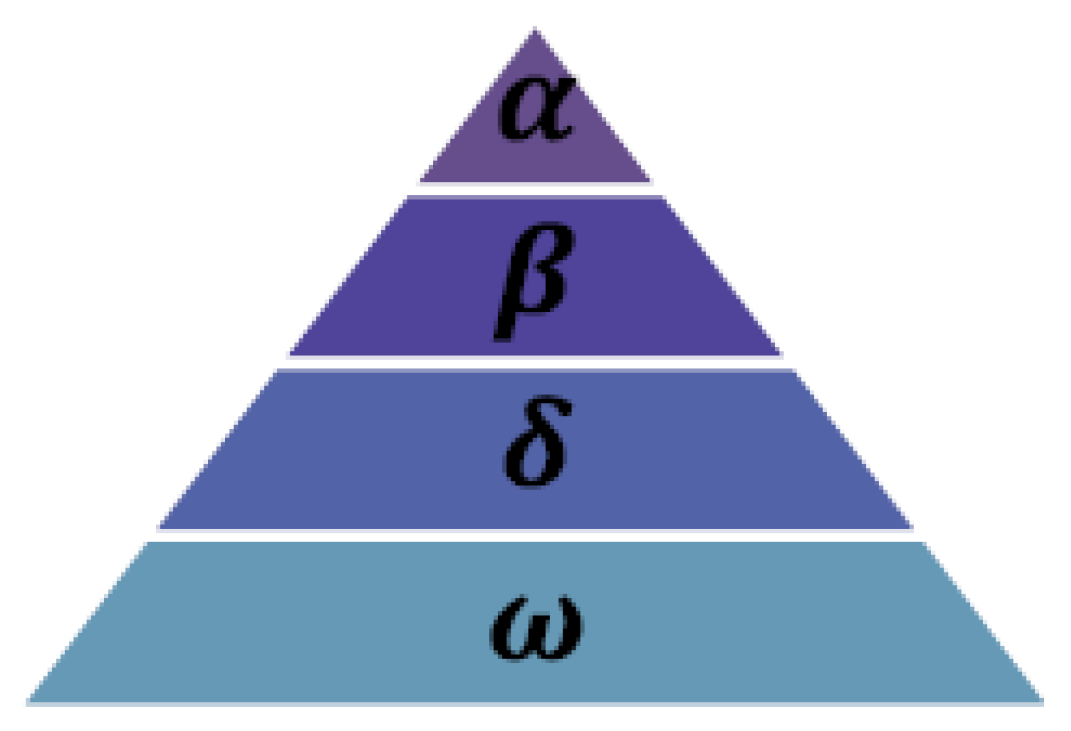
Any optimization problem that postulates the best solution, or alpha (α), can be solved mathematically by illustrating the wolf’s social hierarchy. The expressions “beta” (β) and “delta” (δ) refer to the second- and third-best solutions, respectively, while “omega” (ω) refers to other options.

2.3.1. Method for Hunting Gray Wolves

In explaining and teaching the gray wolf algorithm, we can say that this algorithm consists of 3 main steps:
  • Track, search, chase, and approach the potential prey.
  • Harass and encircle a prey until the prey no longer moves.
  • Attack the prey.
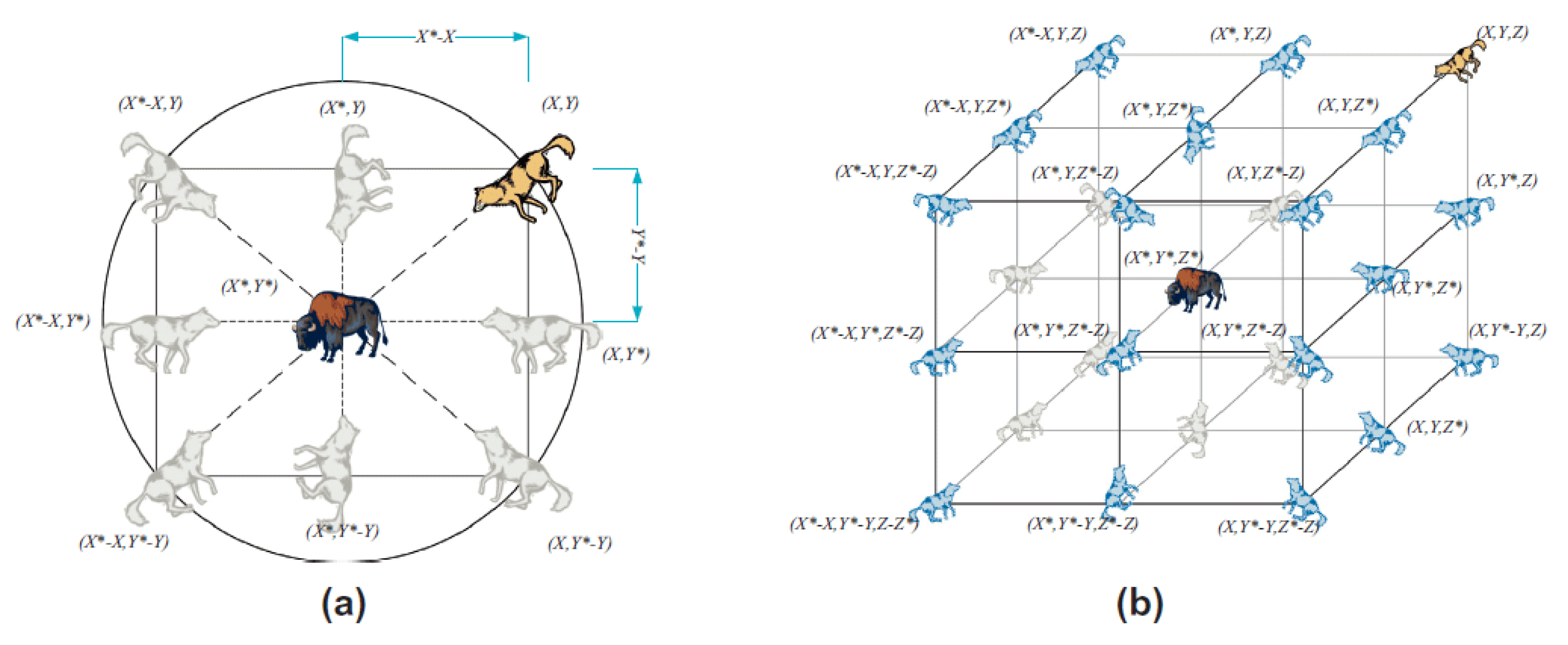
Figure 5a shows the effects of Equations (1) and (2), some possible neighbors, and a 2D positional vector. The mentioned figure also illustrates the wolf’s position (X, Y) that changes/updates with respect to the prey’s location (X*, Y*). The contents of A and C vectors can be adjusted to attain places close to the best agent. Here, (X* − X, Y*) serves as an example that we can reach by adjusting A = (1,0) and C = (1,1). In Figure 5b, a grey wolf’s possible updated positions are depicted in a 3D space. It is important to understand that wolves can access any location among the points because of the accidental vectors r 1 and, r 2 as Figure 5 illustrates. Consequently, a gray wolf may update its location in any random location in the space surrounding the prey using Equations (1) and (2).
The attack is commanded by the alpha wolf as the prey is surrounded by wolves and do not move anymore. The reduction of the vector an is used to model this process. The coefficient vector A reduces as (a) lowers since it is an accidental vector in the range [−2a, 2a]. The wolf alpha will approach the prey (and the other wolves) if |A| < 1, and the wolf will avoid the prey (and the rest of the wolves) if |A| > 1. All wolves must update their positions in accordance with the positions of the alpha, beta, and delta wolves according to the gray wolf algorithm.
During the hunt, gray wolves surround the predation. The equations that follow provide a mathematical representation of the siege behavior. In the relations below the current iteration t, A, and C are coefficient vectors, Xp is the prey position vector and X is the position vector of the gray wolf.
D = | C . X p ( t ) X n ( t ) |
X n ( t + 1 ) = X p ( t ) A . D
Vectors A and C are calculated as follows:
A = 2 a . r 1 a
C = 2 r 2
Here, r 1   and r 2   are the accidental vectors [0, 1] and after iterations, a components have been linearly reduced from 2 to 0.
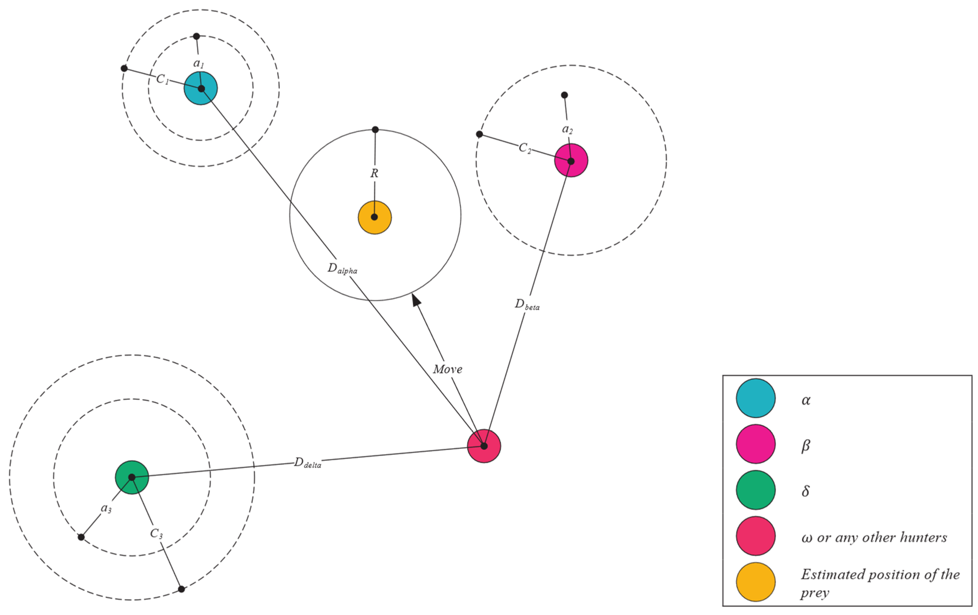
Searching and excavation operations will be typically directed by alpha. Beta and delta
D α = | C 1 . X α X | ,   D β = | C 2 . X β X | ,   D δ = | C 3 . X δ X |
X 1 = X α A 1 . ( D α ) ,     X 2 = X β A 2 . ( D β ) ,   X 3 = X δ A 3 . ( D δ )
X n ( t + 1 ) = X 1 + X 2 + X 3 3
The search steps are shown in Figure 6.
To conclude, the search for an optimized solution, or in other words, prey, initiates with creating random grey wolves’ population (or candidate solutions) using the GWO algorithm. After a considerable number of iterations, three top wolves (alpha, beta, and delta) estimate the prey’s position. Based on that, every candidate solution (wolf) changes (updates) its distance from the selected prey. To explore and exploit further, we reduced the parameter a from 2 to 0. As | A | > 1, the candidate solutions diverge from the prey, however when | A | < 1 is true, the candidate solutions converge toward the prey. At the end, when the end criterion is met, we terminate the GWO.
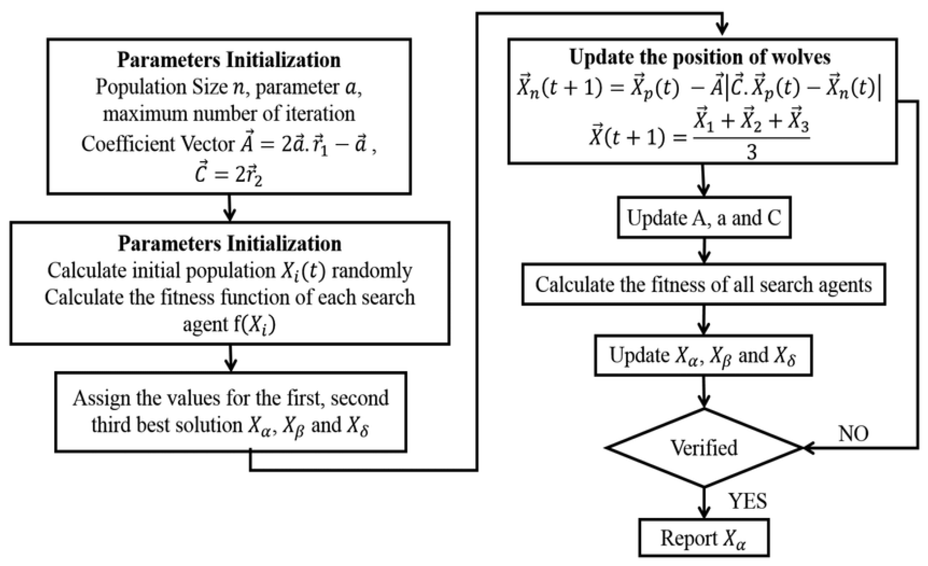
According to the contents of the flowchart, the gray wolf algorithm can be considered as follows. This flowchart will only work by specifying the values of vectors A and C. Explaining this flowchart is very simple by studying the above-mentioned steps. Figure 7 indicated the Flowchart of the Gray Wolf Algorithm.
This looks and introduces the grey wolf optimizer into a unique set of rules to generate the global seek vector for decreasing the characteristic numbers from the fault indicators that created by guide enforcing in Simulink to attain the capabilities for global exploration. Numerous steps are contained in the gray wolf optimizer:
(1)
Social hierarchy mechanism
According to their fitness values, the wolves are separated into 4 groups (W1, W2, W3, and W4). The first three groups have the ability to control the wolves and are made up of excellent adaptable gray wolves.
(2)
Surround the prey
The grey wolves must surround their prey while predation. A mathematical model can be found here:
S = | Q 2 × Z P ( x ) Z ( x ) |
Z ( x + 1 ) = Z P ( x ) Q 1 × S
In which x represents the cutting-edge new release number. S is the distance and route of the wolf from its prey. Z P is the location of the prey. Z gives the placement of the wolves. Q 1 and Q 2 are coefficient vectors and can be described as follows:
Q 1 = a ( 2 × r a n d ( 0 , 1 ) 1 )
Q 2 = 2 × r a n d ( 0 , 1 )
In this equation a is factor of attenuation.
When the range of iterations rises, the coefficient experiences a linear decrease from 2 to zero.
(3)
Hunting
The wolf W1 instructs wolves W2 and W3 to reduce the prey’s surrounding circle (domain) in order to gain the motive for hunting. The mathematical model is given as:
{ S W 1 = | Q 2 × Z W 1 ( x ) Z ( x ) | S W 2 = | Q 2 × Z W 2 ( x ) Z ( x ) | S W 3 = | Q 2 × Z W 3 ( x ) Z ( x ) |
{ Z 1 = Z W 1 Q 1 × S W 1 Z 2 = Z W 2 Q 1 × S W 2 Z 3 = Z W 3 Q 1 × S W 3
where,   Z W 1   Z W 2 , Z W 3 indicate the positions of wolf W1, wolf W2 and wolf W3, respectively. Z gives the location and position information belonging to the remaining wolves. S W 1 , S W 2 , S W 3 indicate the rout and step size (step length) of wolf W4 which moves toward wolf W1, wolf W2 and wolf W3, respectively.
(4)
Generation a global search vector
The global search vector is defined as the following:
V = V + r a n d × ( Z 1 + Z 2 + Z 3 3 P P ( x ) )
The improved position update formula is as follows:
P p ( x + 1 ) = P p ( x ) + P p ( x + 1 ) + V 3
In Equation (15) the features from the created data matrix can be obtained. These features will be used in the training of the neural network.

2.3.2. Hybrid GWO-PI Controller

In this section, the development of H-GWO-PI controller is presented. 
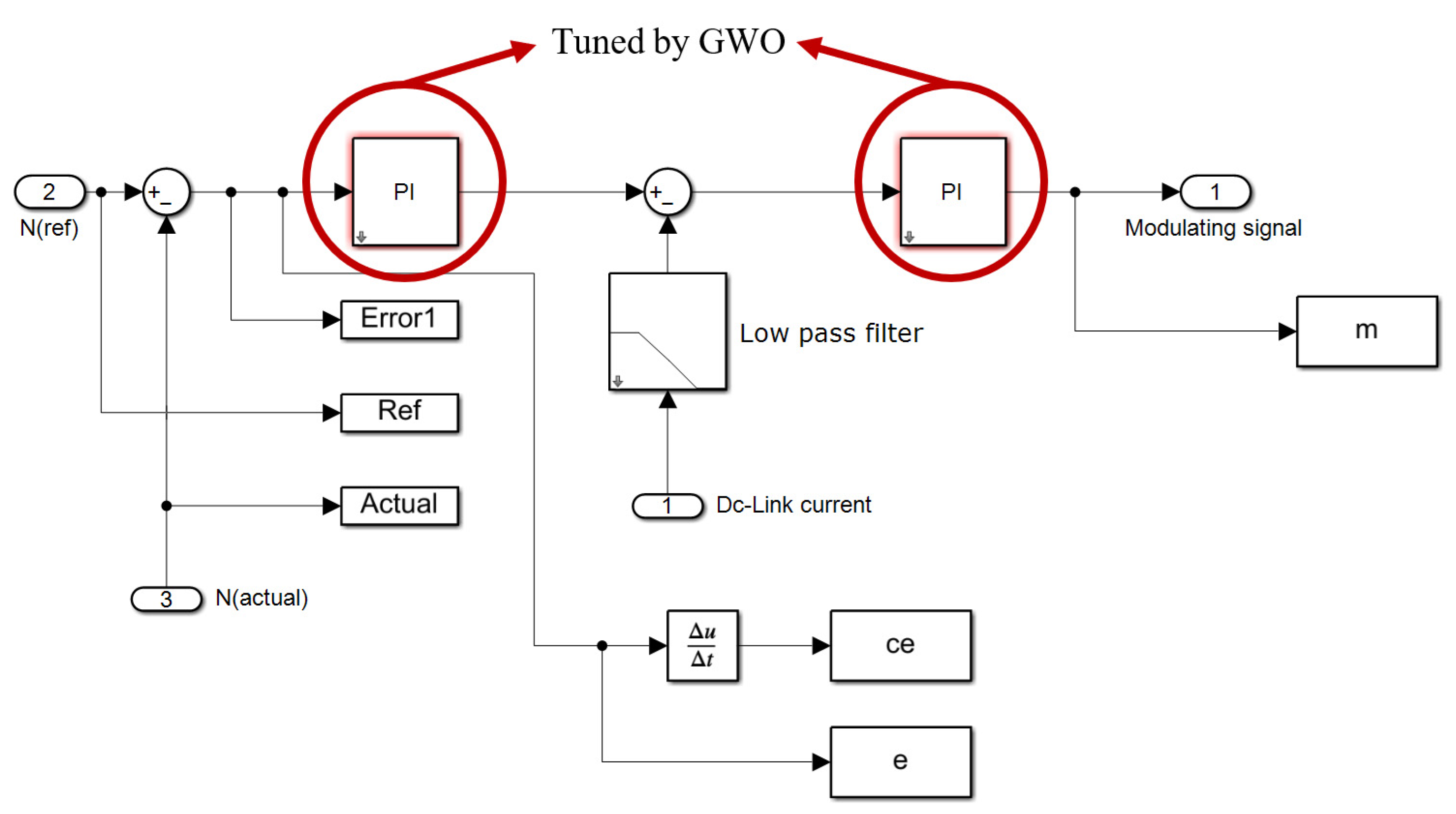
Figure 8 shows the Simulink model for H-GWO-PI controller. In this figure, GWO tuner provides the gain contents for the PI controller regarding to the reference value and the actual value of error.
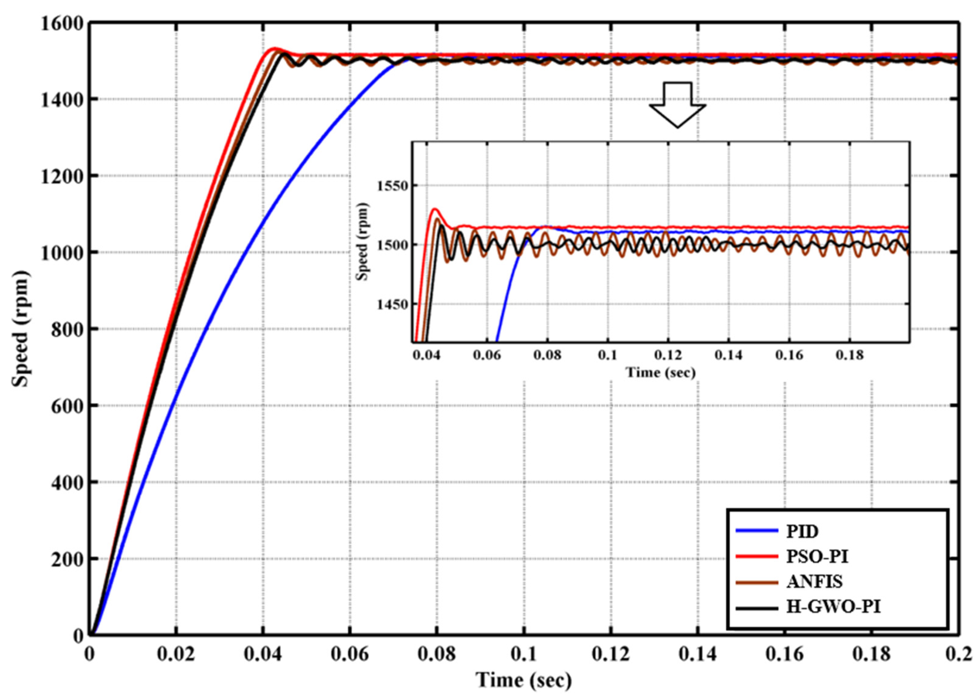
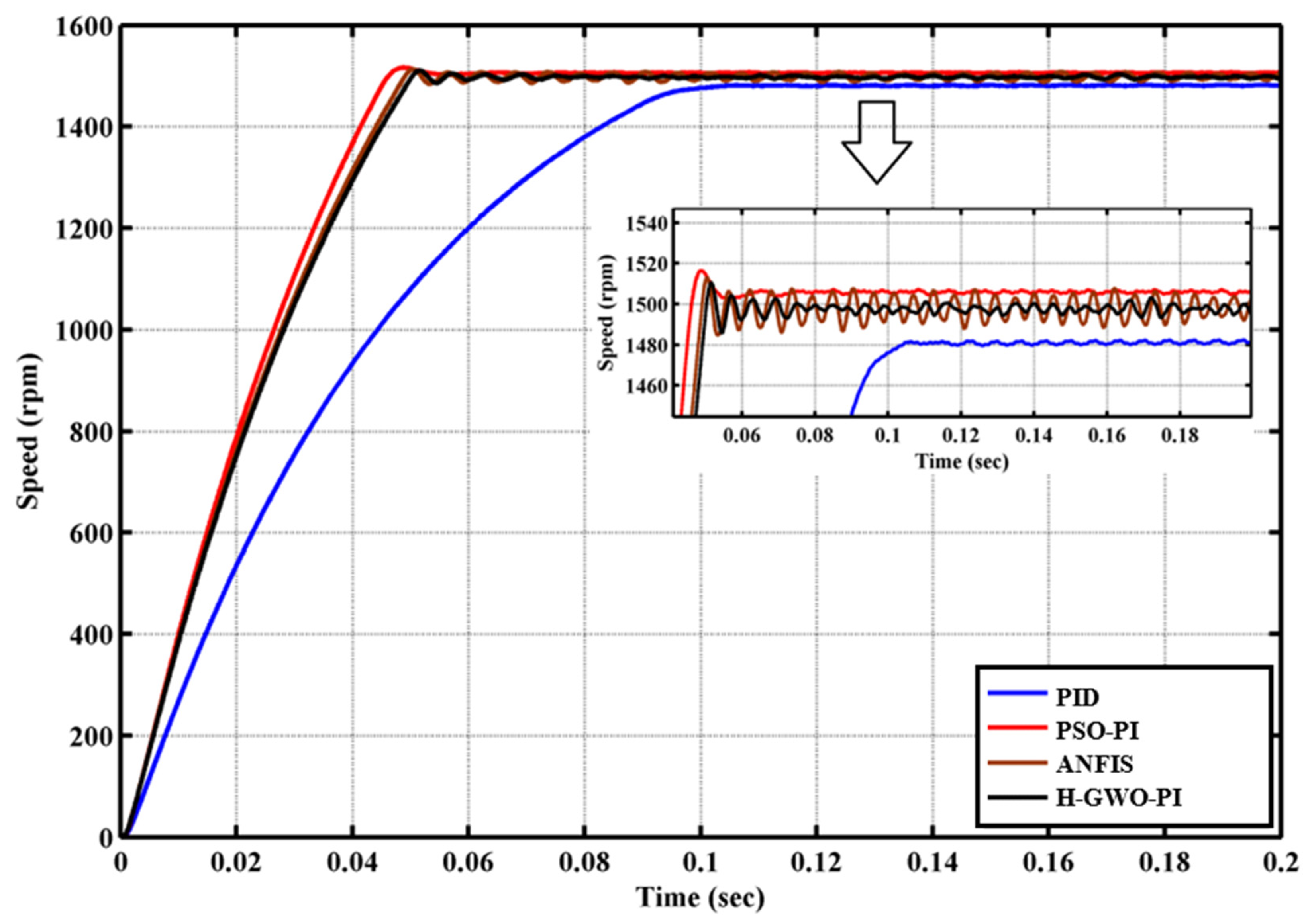
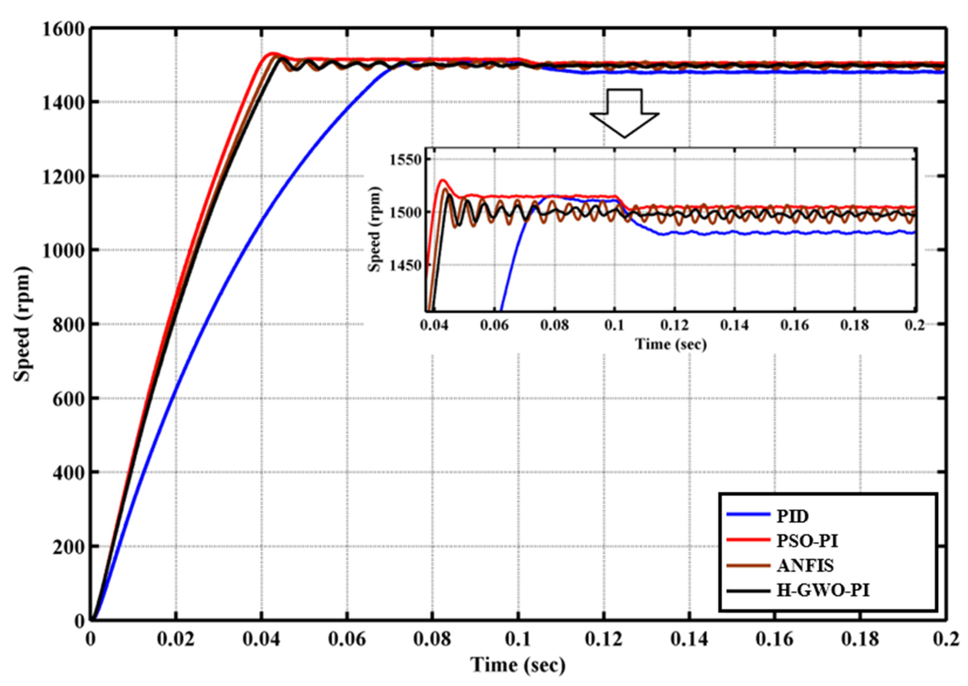
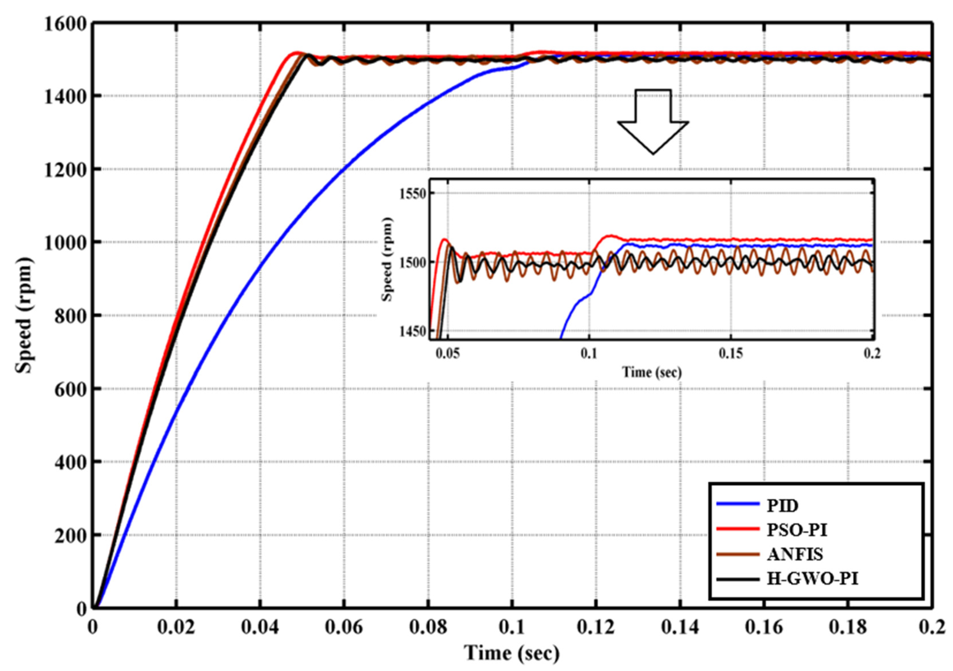
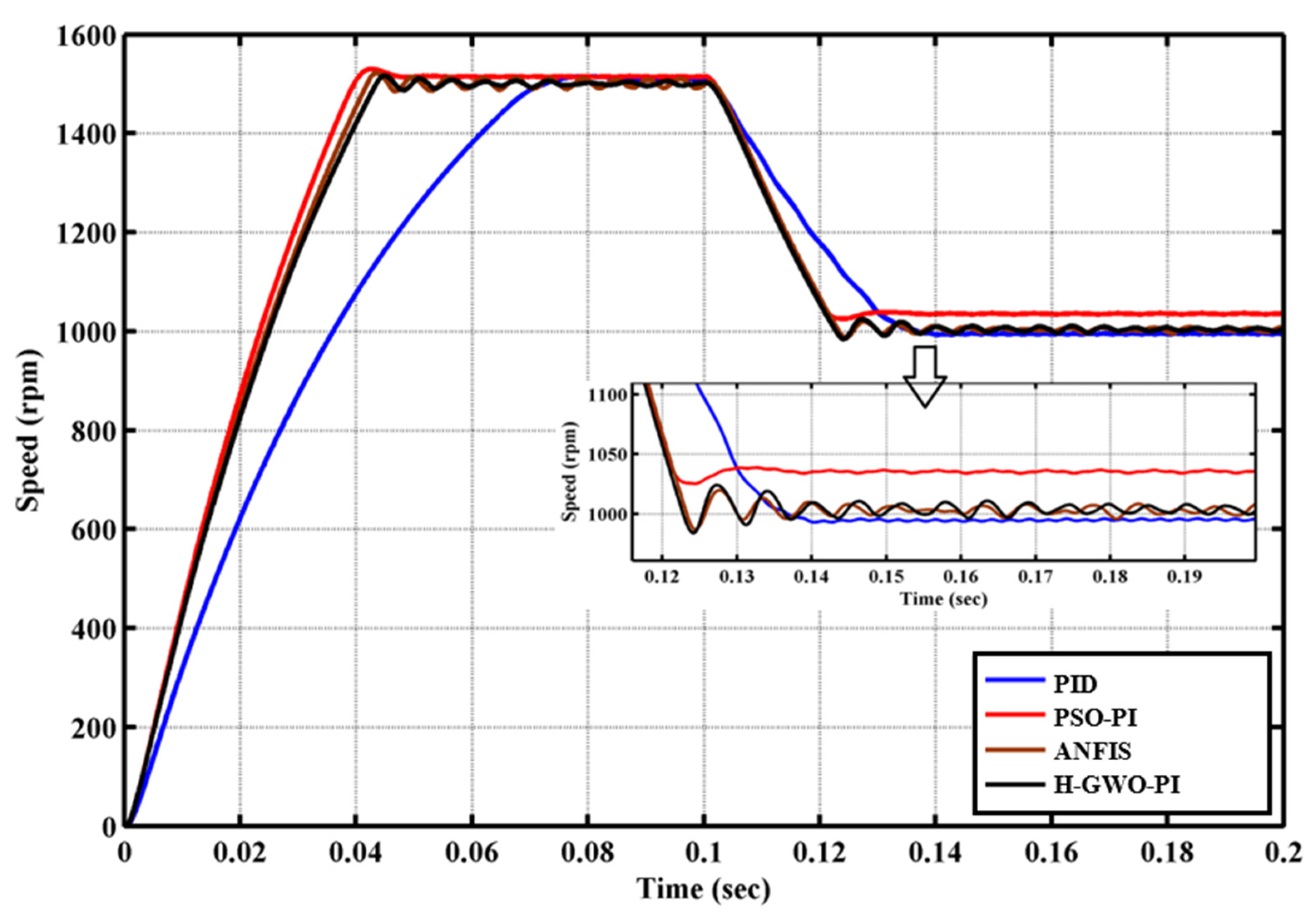
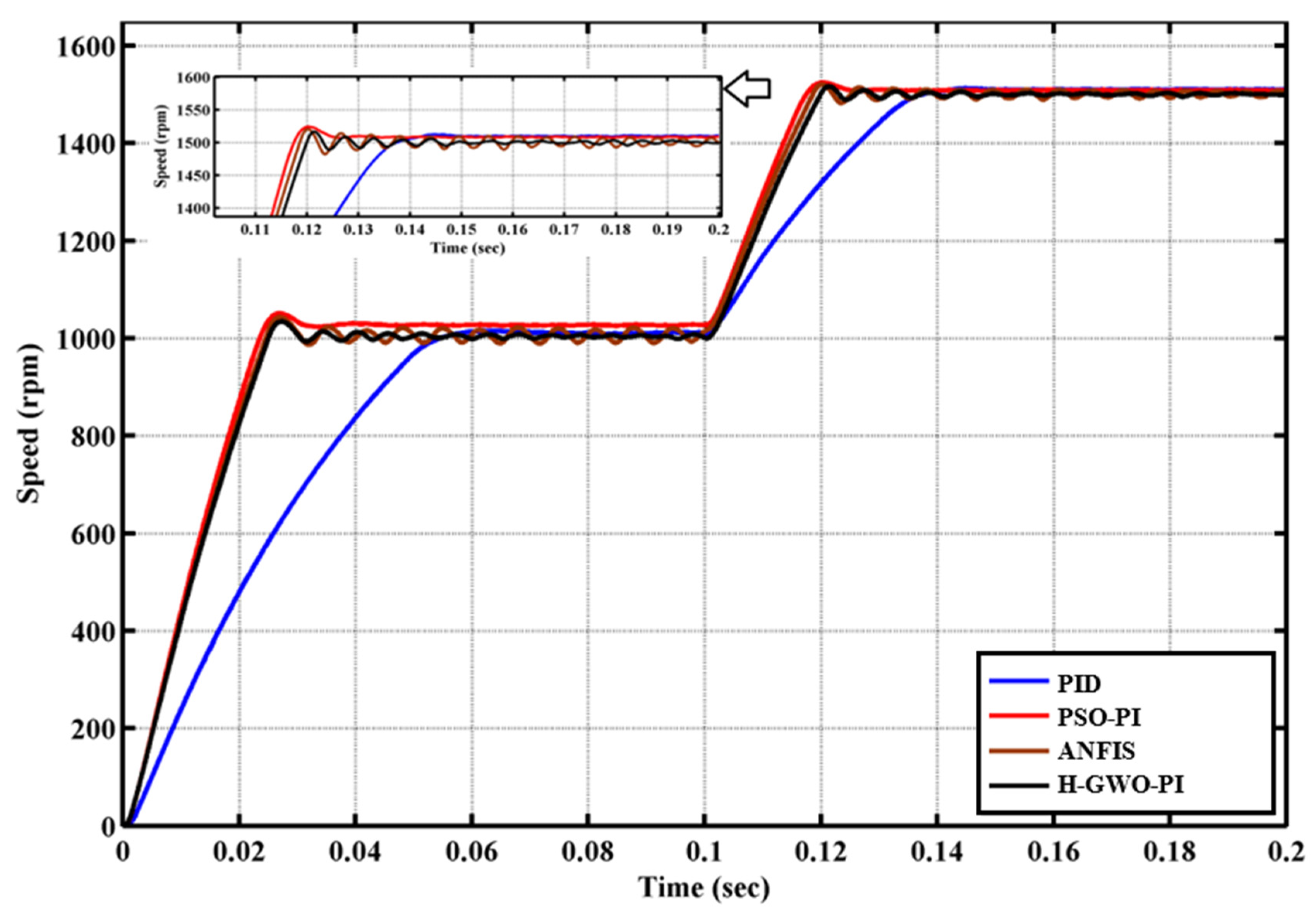
The speed response of the contemplated Brush-less DC motor is examined for fixed load situations, varying set speed situations and varying load situations. Time domain parameters and performance indices for the hybrid GWO-PI are obtained and compared, including recovery time, settling time, rising time, steady state error, undershoot, overshoot, RMSE, ITAE, IAE, and ISE PID controller, PSO-PI controller, ANFIS controller, hybrid GWO-PI. The BLDC motor’s characteristics have been extracted from [26].
As seen in Figure 8, the Error1 is the input of the first controller (speed PI controller), and the difference between output of first Speed PI controller and the filtered current value is the input of the second current PI controller. The red colored circle and direction shows the PI controller tuned by GWO algorithm. The objective function is the error between reference and the actual value. The aim of this objective function is reducing the error value.
O b j e c t i v e   F u n c t i o n   = a b s ( R e f e r e n c e s p e e d a c t u a l   S p e e d   o f   t h e   m o t o r ) + a b s ( R e f e r e n c e   c u r r e n t a c t u a l   c u r r e n t   o f   t h e   b l d c   m o t o r )
The absolute value of the error speed and error current is measured from the simulation for different set of values of the PI controller’s parameter from the GWO algorithm. After completion of maximum iteration, GWO provide optimal parameter results for the PI controllers such as Kp1, Ki1, Kp2 and Ki2. The limits or constraints for the control variables such as Kp1, Ki1, Kp2, and Ki2 are between 0.01 (Lower bound) to 3 (Upper bound). The GWO provide the values for two PI controllers such as Kp1, Ki1, Kp2, and Ki2. For each set of population, measuring objective function value stated in the Equation (22). For each iteration, best results are stored separately, and end of the final iteration, GWO provide the optimal parameters for the two PI controllers.

3. Results and Discussion

A.
Results for Constant Load Case
The specification BLDC motor are as follows, rated power is 10 KW, rated voltage is 48 V, rated speed is 1500 rpm and rated torque is 27 nm. A brush-less DC motor’s speed response is simulated for both full load and no load conditions and the findings are provided in this section. For a set speed of 1500 rpm and no load case, Figure 9 depicts the curve of speed response. Table 1 lists the corresponding performance metrics.
In Table 1, maximum value of each column parameter is taken as the base value for comparisons. From this table, PID controller is worst in terms of rise time, Settling Time, ITAE RMSE, ISE and IAE. The PSO-PI controller has the worst overshoot and steady state error. ANFIS controller performs well than PID and PSO-PI controller. But the proposed controller is the only one that benefits from all performance factors i.e., Hybrid GWO-PI controller. With respect to the comparison outcomes, it is obvious that Hybrid GWO-PI controller is the best controller among other considered controllers. Figure 10 indicates the curve of speed response for full load situation (15 nm). Table 2 provides the controllers’ performance indices and the corresponding time domain specifications.
In Table 2, maximum value of each column parameter is taken as the base value for comparisons. From this table, PID controller is the poorest in regard to all parameters except overshoot. Regarding steady state error, undershoot and RMSE, the PSO-PI controller exhibits insignificant behavior. ANFIS controller performs well in terms all parameters than PID and PSO-PI controller. But Hybrid GWO-PI controller produces better performance in all vital parameters compared to other controllers considered.
B.
Results for Varying Load Conditions
The drive is consistently exposed to differing load situations for various applications in the industry. In order to assess the advantage of the proposed controller, an abrupt alternation in load conditions is used to operate the closed loop system of the Brush-less DC motor. In this section, two examples’ speed reactions under several load situations are discussed. For instance in case A, the speed is set at 1500 rpm and the load is altered starting from zero to maximum (15 nm) in 0.1 s. In case B, the load is reduced starting from full load situation (15 nm) to No load (zero nm) situation in 0.1 s while the speed of the BLDC motor is equal to 1500 rpm.
The speed response curves for case A are shown in Figure 11. When the load changes from zero to full, the motor speed should decrease. However, a motor controlled by a PID and PSO-PI controllers has a significant departure from its set speed. Motor speed fluctuates by up to 5 rpm around the programmed speed when using a PSO-PI controller. However, a Hybrid GWO-PI controller causes the motor speed to fluctuate around 1.8 rpm. Overshoot is another crucial characteristic; it should be kept to a minimum as much as is practical. Any abrupt change in the load raises the case. For motors using PID and PSO-PI controllers, overshoot is particularly high. For a motor using a ANFIS controller, overshoot is mild. However, the motor with the suggested controller only overshot by 0.14%. Table 3 presents performance parameters including time domain requirements and performance indices. The maximum value for each column parameter in this table is used as the baseline for comparisons. The PID controller does not benefit from the performance indices shown in this table. Both the PSO-PI and ANFIS controllers have performance criteria that are moderated. But compared to other controllers under consideration, the proposed controller performs better.
A brush-less DC motor’s speed response is shown in Figure 12 as the load changes from being fully loaded to being unloaded and Table 4 gives the related control system parameters. Speed will increase when a rapid load rejection occurs, and the speed error should be as small as possible. The steady state error of a motor with PID and PSO-PI controllers is greater. Moderate steady state error for motor using ANFIS controller. However, the Hybrid GWO-PI controller motor only has a stable inaccuracy of 1.12 rpm. Important parameters like speed overshoot, should be kept to a minimum. Compared to alternative controllers examined, the suggested has the least overshoot. The maximum value for each column parameter in Table 4 is used as the comparison standard. Based on this information, a motor using a PID controller has the poorest RMSE, ITAE, and ISE. The motor equipped with the PSO-PI controller performs the poorest in terms of steady state error, overshoot and RMSE. In comparison to the proposed controller and the PSO-PI controller, the motor with the ANFIS controller has a modest performance parameter. But compared to other controllers under consideration, the motor containing the suggested controller exhibits better performance parameters.
C.
Results Under Various Set Speed Conditions
The drives set speed is altered in process industry in accordance with process demands. To confirm the effectiveness of the recommended controllers for those settings, two conditions for operating with varying set speeds are hypothesized and simulated. In cases C and D, the set speed is first altered from 1500 to 1000 rpm and later, from 1000 to 1500 rpm, respectively. The load is set to zero in both situations.
The speed response for the Case C scenario is represented in Figure 13. Table 5 displays the pertinent performance metrics. For comparisons, the maximum value for each column was used as the base value. According to this table, the PID controller has the poorest RMSE, IAE, ITAE, and ISE values. In terms of Undershoot, Recovery Time (s), and Steady state error (rpm), PSO-PI performs the poorest. Regarding steady state error, recovery time, ITAE, ISE, RMSE and IAE, Hybrid GWO-PI performs better than other controllers.
The speed response of the Brush-less DC motor in the Case D scenario is represented in Figure 14 and the corresponding performance metrics are shown in Table 6. For comparisons, the maximum value of each column parameter is used as the baseline. Except for the motor with the proposed controller, the system responds oscillatory to all other controllers. Additionally, compared to the other controllers, this one created a reduced steady state error. The steady-state error for the Hybrid GWO-PI controller is 0.74963 rpm. Only the proposed controller and the ANFIS controller benefit from an overshoot. PSO-PI controllers perform worse than other controllers on performance indicators. Compared with PID controllers, ANFIS and PSO-PI controllers perform best. However, compared to other controllers, the Hybrid GWO-PI controller provides better performance metrics. The Hybrid GWO-PI controller has demonstrated improved performance in all operating circumstances compared to other proposed controllers for Brush-less DC motor.
The Kp and Ki values for each PI controller is shown in Table 7.
As seen in Figure 8, there are two PI controller that tuned by the GWO, PSO and ANFIS. For the left side controller, the coefficients were Kp1 and Ki1. For the right-side controller, the coefficients were Kp2 and Ki2. The value of the coefficient for PI controller are selected between 0.01 to 3. These values are obtained after ten times running of each method. For conventional PID controller parameters Kp1, Ki1, Kd1, Kp2, Ki2, and Kd2 are tuned by ZN method and it is reported in Table 7.

4. Conclusions

To improve the performance of Brush-less DC motors, this research has given systematic methods using artificial intelligence techniques. MATLAB/Simulink software is utilized in order to design and execute the suggested controllers. The efficiency of the controllers has been examined and evaluated for different operation circumstances of Brush-less DC motor. Under all operational scenarios, the Hybrid GWO-PI controller outperforms other contenders regarding the enhanced time domain specifications and enhanced performance indices. The controller proposed, can resolve the indeterminacy problem brought on by load and set speed fluctuations. Outstanding behavior of the controller makes it the perfect choice for use in the processing industry. In the best scenario, the results have been obtained for case B, and it was 1.26840%, 0.19536, 15.81742, 0.32481, 0.03102, 0.00079, and 0.01923 for overshoot, recovery Time (s), steady state error (rpm), RMSE, IAE, ITAE, and ISE respectively.

Author Contributions

Methodology, S.M.Y.Y.; Software, J.R.; Validation, U.K.; Formal analysis, F.H. All authors have read and agreed to the published version of the manuscript.

Funding

This research received no external funding.

Conflicts of Interest

The authors declare no conflict of interest.

References

  1. Krishnan, R. Switched Reluctance Motor Drives: Modeling, Simulation, Analysis, Design, and Applications; CRC Press: Boca Raton, FL, USA, 2017; ISBN 1315220067. [Google Scholar]
  2. Miller, T.J.E. Brushless Permanent-Magnet and Reluctance Motor Drives; Clarendon Press: Oxford, UK, 1989. [Google Scholar]
  3. Sathyan, A.; Milivojevic, N.; Lee, Y.-J.; Krishnamurthy, M.; Emadi, A. An FPGA-Based Novel Digital PWM Control Scheme for BLDC Motor Drives. IEEE Trans. Ind. Electron. 2009, 56, 3040–3049. [Google Scholar] [CrossRef]
  4. Bharatkar, S.S.; Yanamshetti, R.; Chatterjee, D.; Ganguli, A.K. Dual-Mode Switching Technique for Reduction of Commutation Torque Ripple of Brushless Dc Motor. IET Electr. Power Appl. 2011, 5, 193–202. [Google Scholar] [CrossRef]
  5. Lai, Y.-S.; Lin, Y.-K. A Unified Approach to Zero-Crossing Point Detection of Back EMF for Brushless DC Motor Drives without Current and Hall Sensors. IEEE Trans. Power Electron. 2010, 26, 1704–1713. [Google Scholar] [CrossRef]
  6. Gambetta, D.; Ahfock, A. New Sensorless Commutation Technique for Brushless DC Motors. IET Electr. Power Appl. 2009, 3, 40–49. [Google Scholar] [CrossRef]
  7. Akkaya, R.; Kulaksız, A.A.; Aydoğdu, Ö. DSP Implementation of a PV System with GA-MLP-NN Based MPPT Controller Supplying BLDC Motor Drive. Energy Convers. Manag. 2007, 48, 210–218. [Google Scholar] [CrossRef]
  8. Singh, B.; Singh, S. Single-Phase Power Factor Controller Topologies for Permanent Magnet Brushless DC Motor Drives. IET Power Electron. 2010, 3, 147–175. [Google Scholar] [CrossRef]
  9. Gao, J.; Hu, Y. Direct Self-Control for BLDC Motor Drives Based on Three-Dimensional Coordinate System. IEEE Trans. Ind. Electron. 2009, 57, 2836–2844. [Google Scholar]
  10. Karthikeyan, J.; Sekaran, R.D. Current Control of Brushless Dc Motor Based on a Common Dc Signal for Space Operated Vehicles. Int. J. Electr. Power Energy Syst. 2011, 33, 1721–1727. [Google Scholar] [CrossRef]
  11. Joice, C.S.; Paranjothi, S.R.; Kumar, V.J.S. Digital Control Strategy for Four Quadrant Operation of Three Phase BLDC Motor with Load Variations. IEEE Trans. Ind. Inform. 2012, 9, 974–982. [Google Scholar] [CrossRef]
  12. Demirtas, M. Off-Line Tuning of a PI Speed Controller for a Permanent Magnet Brushless DC Motor Using DSP. Energy Convers. Manag. 2011, 52, 264–273. [Google Scholar] [CrossRef]
  13. Ibrahim, H.E.A.; Hassan, F.N.; Shomer, A.O. Optimal PID Control of a Brushless DC Motor Using PSO and BF Techniques. Ain Shams Eng. J. 2014, 5, 391–398. [Google Scholar] [CrossRef] [Green Version]
  14. Rubaai, A.; Castro-Sitiriche, M.J.; Ofoli, A.R. DSP-Based Laboratory Implementation of Hybrid Fuzzy-PID Controller Using Genetic Optimization for High-Performance Motor Drives. IEEE Trans. Ind. Appl. 2008, 44, 1977–1986. [Google Scholar] [CrossRef]
  15. Siong, T.C.; Ismail, B.; Siraj, S.F.; Mohammed, M.F. Fuzzy Logic Controller for BLDC Permanent Magnet Motor Drives. Int. J. Electr. Comput. Sci. 2011, 11, 13–18. [Google Scholar]
  16. Shyam, A.; Febin Daya, J.L. A Comparative Study on the Speed Response of BLDC Motor Using Conventional PI Controller, Anti-Windup PI Controller and Fuzzy Controller. In Proceedings of the 2013 International Conference on Control Communication and Computing (ICCC), Thiruvananthapuram, India, 13–15 December 2013; pp. 68–73. [Google Scholar]
  17. Al Gizi, A.J.H.; Mustafa, M.W.; Jebur, H.H. A Novel Design of High-Sensitive Fuzzy PID Controller. Appl. Soft Comput. 2014, 24, 794–805. [Google Scholar] [CrossRef]
  18. Sahu, B.K.; Pati, S.; Mohanty, P.K.; Panda, S. Teaching–Learning Based Optimization Algorithm Based Fuzzy-PID Controller for Automatic Generation Control of Multi-Area Power System. Appl. Soft Comput. 2015, 27, 240–249. [Google Scholar] [CrossRef]
  19. Wang, Y.; Xia, C.; Zhang, M.; Liu, D. Adaptive Speed Control for Brushless DC Motors Based on Genetic Algorithm and RBF Neural Network. In Proceedings of the 2007 IEEE International Conference on Control and Automation, Guangzhou, China, 30 May 2007–1 June 2007; pp. 1219–1222. [Google Scholar]
  20. Cheng, Z.; Hou, C.; Wu, X. Global Sliding Mode Control for Brushless DC Motors by Neural Networks. In Proceedings of the 2009 International Conference on Artificial Intelligence and Computational Intelligence, Shanghai, China, 7–8 November 2009; Volume 4, pp. 3–6. [Google Scholar]
  21. Sinanc, D.; Sahin, M.; Esen, Z.; Yavanoglu, U.; Sagiroglu, S. An Intelligent Feedback Control Mechanism for Brushless DC Motors. In Proceedings of the 2014 16th International Power Electronics and Motion Control Conference and Exposition, Antalya, Turkey, 21–24 September 2014; pp. 939–944. [Google Scholar]
  22. Faieghi, M.R.; Azimi, S.M. Design an Optimized PID Controller for Brushless DC Motor by Using PSO and Based on NARMAX Identified Model with ANFIS. In Proceedings of the 2010 12th International Conference on Computer Modelling and Simulation, Cambridge, UK, 24–26 March 2010; pp. 16–21. [Google Scholar]
  23. Varatharaju, V.M.; Mathur, B. Adaptive Controllers for Permanent Magnet Brushless DC Motor Drive System Using Adaptive-Network-Based Fuzzy Interference System. Am. J. Appl. Sci. 2011, 8, 810. [Google Scholar] [CrossRef]
  24. Mosavi, M.-R.; Rahmati, A.; Khoshsaadat, A.; Elektrotechniczny, P. Design of Efficient Adaptive Neuro-Fuzzy Controller Based on Supervisory Learning Capable for Speed and Torque Control of BLDC Motor. Przegląd Elektrotechniczny 2012, 88, 238–246. [Google Scholar]
  25. Deying, G.; Jinquan, Z. Speed Control of BLDCM Based on Compensated Fuzzy Neural Network. In Proceedings of the The 26th Chinese Control and Decision Conference (2014 CCDC), Changsha, China, 31 May–2 June 2014; pp. 4541–4544. [Google Scholar]
  26. Premkumar, K.; Manikandan, B. V Adaptive Neuro-Fuzzy Inference System Based Speed Controller for Brushless DC Motor. Neurocomputing 2014, 138, 260–270. [Google Scholar] [CrossRef]
  27. Mirjalili, S.; Mirjalili, S.M.; Lewis, A. Grey Wolf Optimizer. Adv. Eng. Softw. 2014, 69, 46–61. [Google Scholar] [CrossRef]
  28. Hassan, H.A.; Zellagui, M. Application of Grey Wolf Optimizer Algorithm for Optimal Power Flow of Two-Terminal HVDC Transmission System. Adv. Electr. Electron. Eng. 2018, 15, 701–712. [Google Scholar] [CrossRef]
  29. Shaikh, M.S.; Hua, C.; Jatoi, M.A.; Ansari, M.M.; Qader, A.A. Application of Grey Wolf Optimisation Algorithm in Parameter Calculation of Overhead Transmission Line System. IET Sci. Meas. Technol. 2021, 15, 218–231. [Google Scholar] [CrossRef]
  30. Guha, D.; Roy, P.K.; Banerjee, S. Load Frequency Control of Large Scale Power System Using Quasi-Oppositional Grey Wolf Optimization Algorithm. Eng. Sci. Technol. Int. J. 2016, 19, 1693–1713. [Google Scholar] [CrossRef] [Green Version]
Figure 1. (a) Typical inverter systems for a BLDC motor, (b) Brushless DC motor’s speed control system.
Energies 16 01640 g001
Figure 2. Formation of a conventional PID controller.
Energies 16 01640 g002
Figure 3. Simulink model of a conventional PID controller.
Energies 16 01640 g003
Figure 4. Hierarchies of the gray wolf [27].
Energies 16 01640 g004
Figure 5. Gray wolf’s structures to get prey, (a) 2D and (b) 3D position vectors [27].
Energies 16 01640 g005
Figure 6. Search steps [27].
Energies 16 01640 g006
Figure 7. Flowchart of Gray Wolf Algorithm.
Energies 16 01640 g007
Figure 8. Simulink model for H-GWO-PI controller.
Energies 16 01640 g008
Figure 9. The speed response of a brushless DC motor for No-load.
Energies 16 01640 g009
Figure 10. Speed response of the brushless dc motor under full load condition.
Energies 16 01640 g010
Figure 11. Response of the Brush-less DC motor in terms of speed under Case A.
Energies 16 01640 g011
Figure 12. Response of the Brushless DC motor in terms of speed under Case B.
Energies 16 01640 g012
Figure 13. Response of the Brushless DC motor in terms of speed under Case C.
Energies 16 01640 g013
Figure 14. Response of the Brushless DC motor in terms of speed under Case D.
Energies 16 01640 g014
Table 1. No-load condition’s performance parameters.
ControllerRise Time (s)Overshoot (%)Settling Time (s)Steady State Error (rpm)RMSEIAEITAEISE
PID0.05221.02270.067810.88860.29490.02560.000520.01618
PSO-PI0.02991.99950.038314.48560.24320.01760.000290.01131
ANFIS0.03231.01220.02105.138630.19320.01800.000260.01099
H-GWO-PI0.02901.00860.03422.404660.18150.01740.000250.01031
Maximum margin for comparisons0.05221.99950.067814.48560.29490.02560.000520.01618
Table 2. Full load condition’s performance parameters.
ControllerRise Time (s)Overshoot (%)Undershoot (%)Settling Time (s)Steady State Error (rpm)RMSEIAEITAEISE
PID0.07010.00000.00040.095918.83560.32490.03120.00080.0192
PSO-PI0.03781.08500.00050.04756.12730.25710.02930.00030.0133
ANFIS0.03420.87000.00020.04453.98910.18860.01930.00030.0126
H-GWO-PI0.03440.70310.00020.04432.45320.18270.01920.00030.0124
Maximum Margin for Comparisons0.07011.08500.00400.095918.83560.32490.03120.00080.0192
Table 3. Performance parameters for Case A condition.
ControllerOvershoot (%)Recovery Time (s)Steady State Error (rpm)RMSEIAEITAEISE
PID0.698340.2011918.99330.301230.032090.000420.01701
PSO-PI0.992440.159924.302410.302210.018020.000260.01191
ANFIS0.477540.129704.795060.182700.018560.000240.01163
H-GWO-PI0.141150.126901.860810.182490.017350.000240.01130
Maximum Margin for Comparisons0.995530.1600219.852590.295050.025770.000540.01619
Table 4. Performance parameters for Case B condition.
ControllerOvershoot (%)Recovery Time (s)Steady State Error (rpm)RMSEIAEITAEISE
PID0.799230.1953611.992230.324810.029340.000810.01923
PSO-PI1.302230.1201216.09230.257160.020330.000290.01256
ANFIS0.730440.152385.164320.189450.020880.000330.01243
H-GWO-PI0.362100.114841.126200.186190.019280.000300.01233
Maximum Margin for Comparisons1.268400.1953615.817420.324810.031020.000790.01923
Table 5. Performance parameters for Case C condition.
ControllerOvershoot (%)Undershoot (%)Recovery Time (s)Steady State Error (rpm)RMSEIAEITAEISE
PID1.40092.13980.170037.8933220.317640.029170.000910.01747
PSO-PI1.31292.98840.2100052.990040.265590.020700.000610.01236
ANFIS2.60652.13980.210004.592150.205680.021640.000600.01304
H-GWO-PI1.20400.43980.163974.409480.204200.020110.000550.01232
Maximum Margin for Comparisons2.60652.98840.210053.30550.31760.02910.000910.01747
Table 6. Performance parameters for Case D condition.
ControllerOvershoot (%)Recovery Time (s)Steady State Error (rpm)RMSEIAEITAEISE
PID0.902230.199029.92310.301280.04250.000590.02031
PSO-PI1.702300.140247.991240.199200.020090.000330.00835
ANFIS0.781840.210004.070810.177570.014230.000410.00816
H-GWO-PI0.771030.135960.749630.176770.013840.000300.00804
Maximum Margin for Comparisons1.612210.2100010.005410.281300.023850.000620.01438
Table 7. PI controller parameter for each Method.
Kp1Ki1Kd1Kp2Ki2Kd2
PID0.45530.62210.220.02720.02280.21
PSO-PI0.24011.9494-0.26090.9623-
ANFIS PI2.51842.0793-1.00731.1988-
H-GWO-PI1.42092.9329-0.01000.0100-
Disclaimer/Publisher’s Note: The statements, opinions and data contained in all publications are solely those of the individual author(s) and contributor(s) and not of MDPI and/or the editor(s). MDPI and/or the editor(s) disclaim responsibility for any injury to people or property resulting from any ideas, methods, instructions or products referred to in the content.

