1. Introduction
In order to ensure the best possible reliability of power supply when using more and more renewable energy, today’s power grids undergo a drastic evolution. They have to change from demand-driven architectures to architectures which are supply and demand-driven networks with the ability to handle the volatility of renewable energies and, even more, to satisfy the expected increasing demands [
1]. These new networks are called smart grids [
2], and they are used to describe the communicative connection of the actors in the energy supply system to the power grid, from power generation, transmission, storage and distribution to power consumption. The result is an integrated data and energy network with completely new structures and functions. The networking takes place through the use of information and communication technologies (ICT) as well as decentralized energy management systems to coordinate the individual components. Huge amounts of data are generated and required during the research on smart grids [
3]. This is also the case in technology development, where data are generated in all areas (materials, smart grid technology, power electronics). It is also relevant in the area of smart grid control, where data are provided by models, simulations and experiments in virtual, test and operational grids. The data must be adequately managed, made available and be findable for others, which supports sharing and reuse between different research groups and research fields. Furthermore, semantic interoperability is an important requirement to improve the exchangeability of data [
4]. This allows different tools to access the data without having to convert it into compatible data structures in terms of formats, types and encodings. All these requirements represent a major challenge for intelligent data management. To solve this challenge, up-to-date technologies in research data management have to be applied. One promising approach is given by the FAIR principles, which have been defined by Wilkinson [
5]. FAIR stands for Findable, Accessible, Interoperable, and Reusable, which correspond to the features that have already been identified above. The concept of Digital Objects (DOs) provides solutions to meet the FAIR principles and has recently evolved to the concept of so called FAIR Digital Objects (FDOs) [
6]. The requirement of interoperability is mainly a matter of semantics that can be adequately supported by the utilization of ontologies and standardized schemas.
The aim of the paper is to provide a first solution to the described challenge by combining these promising technologies to a novel energy data management concept.
As an application example a real photovoltaic (PV) system is chosen, which provides a relevant amount of structural and descriptive data for the development of a non trivial concept. Furthermore, in-house expert knowledge exists to develop an adequately detailed model of the system. For this model, different standards and an in-house ontology are used and it is shown how these can be integrated with FDOs. The modeled system can be generically extended, if further components such as a weather station should be added. The concept is agnostic about the used standards and ontologies. Therefore, it can be applied to other energy related facilities as well. As a proof of concept, a use case that visualizes a real PV system, its describing data from sensors that have been installed for research purpose, is designed: methods and components are introduced to gather and collect data as well as a system design and corresponding programming that uses existing data storage solutions and modularizes the tasks of visualizing various aspects of PV systems. It is generalized to be applicable to other use cases as well.
This paper firstly describes the underlying technologies, digital objects, FAIR digital objects and ontologies. The necessity of an own PV ontology and its description are explained. The used standards are explained and presented and the used FDO is defined. The key point of the paper describes the novel approach to integrate ontologies and standards using FDOs. This is followed by an explanation of the generalized application of the concept as well as possible limitations. Then the implementation of the use case is described. The paper concludes with a summary and outlook.
2. Underlying Technologies
This work proposes the integration of FAIR Digital Objects with ontologies to build a metadata environment for data storage and access that adheres to the FAIR principles [
5]. This section introduces these underlying technologies and presents the important related work, in order to accomplish a sound understanding of the overall conceptual approach given in the following section.
2.1. Digital Objects
The term Digital Object (DO) goes back to a paper published by Kahn and Wilensky in 1995, which has been republished in 2006 [
7]. The concept of DOs and the Digital Object Architecture (DOA) will be briefly outlined and then, in the next subsection, lead to the more up-to-date FDOs. It is important to note that the DOs from [
7] are data structures and cannot be used to reference other IT resources directly. Of course, such resources can be described as data structures to suit the DO world.
A DO must have an identifier, named a handle by [
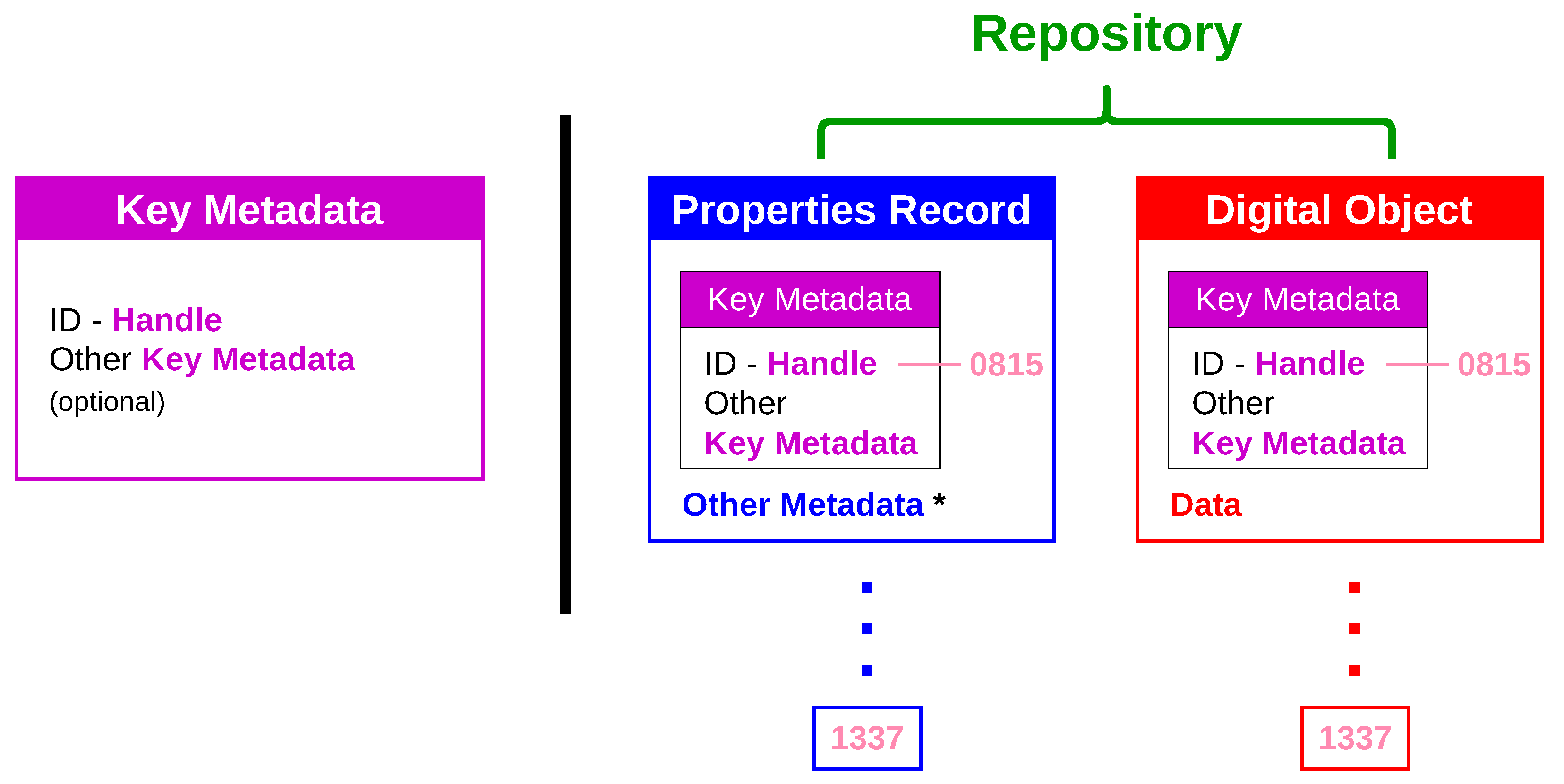
7]. It is explicitly mentioned that handles are not supposed to be manipulated by users directly. Handles are delivered from handle generators. When retrieving a DO, its handle is presented to a handle server, which delivers name and address of a repository where the DO can be requested from. The DOA essentially consists of the handle system and the repositories. Taking a closer look at DOs, the handle is contained in a structure called key metadata, which are all metadata that belong, mandatory or optionally, to all DOs regardless of the application domain. To introduce domain specific metadata, there is a so-called Properties Record in parallel to the DO, that also references key metadata.
Figure 1 shows the properties of DOs with their key metadata and Properties Record as described in [
7].
During the last 20 years, many extensions to the original concept have been proposed, formulated and also implemented: by the DONA Foundation based on the Digital Object Interface Protocol (DOIP) [
8], by the International Telecommunication Union ITU, and by the working group Data Foundation and Terminology in the Research Data Alliance (RDA-DFT). An overview about the features can be found in [
9].
2.2. FAIR
Wilkinson introduced and described the FAIR principles in [
5], which led to the idea of a FAIR ecosystem [
6] and this gave rise to a new branch in the family tree of DOs, namely, the FAIR Digital Objects (FDOs). The authors of [
6] present recommendations which propose models for FDOs and a system of key services for FAIR data management. They state that FDOs cannot exist without these services which they call a FAIR ecosystem. In the following years until now quite a few FAIR implementations have proven the feasibility of the FAIR ecosystem concept, as is shown in [
10]. Schultes and Wittenburg [
11] describe the evolution of FDOs from DOs by extending their definition according to the FAIR principles, particularly by including strong metadata type binding. They also mention the Internet of FAIR Data and Services (IFDS) by GO FAIR (
https://www.go-fair.org/resources/internet-fair-data-services/) that is comparable to the FAIR ecosystem in [
6]. As for the implementation of the FAIR principles, Ref. [
12] gives a detailed interpretations of each principle and also sheds light on possible implementation features, respectively, accompanied by examples of existing solutions. In a recent work [
13], an insight into implementation details of interfaces and tools around the FAIR Data Point metadata repository is given. An important basis for this work is the FDO specification of the FAIR Digital Objects Forum [
14], which is a guideline for the concept presented in this work.
2.2.1. FAIR Principles
The FAIR principles state that research data have to be Findable, Accessible, Interoperable, and Reusable, according to the four letters of the acronym. Essentially, for findability, this means the usage of globally unique persistent identifiers (PIDs), a main concept, called handles back in Kahn and Wilensky’s work [
7]. For accessibility, open, free and standardized protocols are required, which also allow authentication and authorization procedures and provide tombstone information on already deleted data. Most important features that support reusability are accessible data usage licenses, provision of provenance metadata and adhering to open and non-proprietary community standards.
Interoperability in the context of the FAIR principles primarily is semantic interoperability, and most likely the most important principle. First of all, it depends on the language that is used, which has to be a standard language and applicable in a wide range of cases. A vocabulary is needed, that in itself adheres to FAIR and gives a strict and explicit naming. Finally, qualified references must interlink various metadata objects. Among others, this paper holds the view that ontologies are the technology to accomplish these goals.
2.2.2. FAIR Digital Objects
The description of DOs already contains features and properties that also apply to FDOs. What makes these digital objects respectively resources FAIR digital objects is their existence in a FAIR ecosystem with key services enabling FAIR and with the provision of operations to retrieve application data. In contrast to
Figure 1, FDOs comprise key metadata, other metadata and a link to application data. Henceforth, the DOA handle becomes the PID. In [
6], it is pointed out that the implementation of FDOs should rely on vocabularies, ontologie, and other metadata specifications and standards. Ref. [
15] gives a detailed overview of the development, the basic components and the surroundings of FDOs in a digital object world. Furthermore, the DOIP is proposed as a core protocol even for FDOs.
The obligatory set of key metadata can be seen as attached to an FDO’s PID and is also called Kernel Information (KI) or PID record. The specification of the set of metadata used in KI is defined by a Kernel Information Profile (KIP). The Research Data Alliance (RDA) (
https://www.rd-alliance.org/) has released a recommendation paper [
16] proposing 15 attributes KI should include. The Helmholtz Metadata Collaboration (HMC) (
https://helmholtz-metadaten.de/en) uses this recommendation and extends the set of attributes to adapt it to Helmholtz research data requirements. The modified HMC Kernel Information Profile (Helmholtz KIP) will be released soon [
17]. The most important attributes of this profile for the proposed concept are explained in
Table 1.
2.3. Ontologies
2.3.1. Ontologies—Basic Components of Semantic Technology
As a basis for ontology building in the energy domain, starting in this work with a photovoltaics ontology, a combined definition is formulated, that emphasizes various elements which have been discussed in more detail in the literature. The definition is:
Definition 1. An ontology specifies concepts of a knsemaedge domain, their properties and their mutual relationships. It comprises a vocabulary to define the terms, a taxonomy stating the concept hierarchy, and rules to allow for reasoning.
The term
ontology goes back to work of Gruber in the 1990s [
18]. Since then, ontologies have gained a lot of significance in computer science concerning knowledge representation and knowledge processing. Ref. [
19] presents a good overview that supports the main part of the definition given above and also explicitly mentions the significance of ontologies for object-oriented software design and an increasing convergence of both disciplines. More detail on vocabularies and taxonomies as constituting parts of ontologies can be found in [
20] and [
21], respectively. In [
22], ontologies are called a special type of conceptual models and rules and axioms are explicitly noted as a basis for reasoning.
Ref. [
23] is about ontologies in Model Driven Engineering (MDE) and states that the Unified Modeling Language (UML) is suitable for static modeling. In ontology building it allows the definition of the vocabulary, the creation of the taxonomy and the modeling of properties and relations between classes that represent an ontology’s concepts. Additionally, object diagrams support working on instances of an ontology.
Instantiating the concepts described by an ontology delivers objects that describe a real scenario. Properties contain describing data and relations or associations connecting the instances. Thereby, the data are well structured and each concept or instance, respectively, is put into a meaningful context. Ontological methods are thus a kind of best practice, and from the beginning they supported knowledge representation in so-called knowledge bases [
24]. Up to now, ontologies provide benefits for many other communities, e.g., the Semantic Web, as explained in [
25], where also their significance for Big Data is addressed.
Ref. [
26], as early as 1998, states that ontologies
are important for effective communication and also for interoperability and reusability. The latter two are the most important of the four FAIR principles. Frequently, the question of the difference between schemas and ontologies arises. This is an important point which has been studied in many papers, e.g., [
27,
28]. Ref. [
27] makes important statements in writing that conceptual schemas are used for design, whereas ontologies are used at runtime. Furthermore, ontologies should hold application-independent domain knowledge, while schemas are for special applications within enterprises. Yet, both arguments are more on usage and complexity than real differences. Additional axioms that make ontologies logical schemas with the capability for reasoning, as referred to in [
28], are in contrast a valid distinction.
A large number of studies tackle the problem of matching ontologies. In this early stage of ontology development for PV, or energy systems in general, it may not really matter, but already the question of integrating existing ontologies or fragments of existing ontologies came up. It is beyond doubt that this well known challenge will strike this work in the long run, too. So far, for the moment, Ref. [
20] is an appropriate reference to start with this important field of ontology development. Furthermore, Ref. [
29] is about conceptual and ontological modeling in information systems, and therefore of importance for this work since the new PV ontology, in a first step, aims at supporting information systems.
2.3.2. Ontologies for the Energy Domain
In contemporary energy research and energy management, ontologies are already as widespread as in other domains. It shall not be the task of this work to give an overview on the entire energy domain. Nevertheless, in recent years, with the Open Energy Ontology (OEO) [
30], considerable effort has been undertaken to build an ontology that comprises the entire energy system. It relies on the Basic Formal Ontology (BFO) [
31] and is an open community-driven project on GitHub (
https://github.com/OpenEnergyPlatform/ontology).
Since photovoltaics together with wind energy are the major renewable energies and probably the most important representatives of future electricity generating technologies, it is interesting to learn that ontology developments are also in progress for wind energy. In [
32], the authors report on their work to establish a considerable wind energy ontology named OntoWind.
2.3.3. The Subdomain Photovoltaics
Before starting to create an own ontology for photovoltaic systems, already existing approaches have to be examined. There can also be found ontological work in neighboring fields. For example [
33] and [
34] both aim at developing ontologies to describe the knowledge on various methods for solar irradiation forecasting, which shows that ontological modeling goes well beyond modeling of appliances and hardware systems. In [
35], Wang proposes a decision support system that is based on an ontology for solar energy supply and demand analysis. In [
36], it is pointed out that there is a lack of standardization for photovoltaics which prevents an optimal data analysis. The paper concentrates on events and proposes an ontology to semantically integrate event log entries. A similar approach concerning maximum power point tracking (MPPT) (See e.g.,
https://www.aurorasolar.com/blog/the-importance-of-modeling-global-maximum-power-point-tracking/), a method to optimize power output of PV systems, is described by [
37]. In this study, special focus is laid on PV operation under shading conditions, a very relevant point since shading strongly affects power output. To the authors’ best knowledge the Common Information Model (CIM) [
38] does not contain detailed photovoltaics although a bunch of classes also covering solar irradiation have been proposed in [
39]. Ref. [
40] describes a new branch in CIM for facilities connecting to a power grid by power electronics instead of rotating masses and there is a subclass
PhotoVoltaicUnit, but it does not have any photovoltaic specific properties. Therefore, it remains for future effort to built PV into CIM.
The photovoltaic technology ontology system (PV-TONS) is an ontology created to be used in decision systems. It provides a rule-based reasoning mechanism to determine the optimal selection of PV systems and PV components for sustainable buildings. The model, which is already describing a lot of PV system components, has been presented in [
41,
42]. It has been very valuable as a template for the development of the PV ontology introduced in this work, but is insufficient to describe the PV components and their relations to each other with reasonable accuracy for our use case. The SEAS project consists of a bunch of ontologies for the energy domain that especially supports the consumption side. The ontologies are described in detail in [
43]. Built on top of the SEAS Electric Power System Ontology, the Photovoltaic Ontology contains four classes to describe the generating components and a
PowerInverter as a special transformer, as well as a
SolarTracker as a derivative of an actuator. Thus, it contains the basics needed to describe PV systems, and in this respect it is comparable to the OEO [
30] that has been already mentioned. The OEO yet offers a broader approach which is not constrained to a special aspect of energy systems, like e.g., consumption in the SEAS ontologies. The PV-related classes in this ontology are also relying on and embedded into a basis of electrical component classes, and due to this all-encompassing scope, OEO has the most promising solution for an ontological description of PV from the point of view of energy research data management and its metadata requirements. Nevertheless, it has been decided to develop an own ontology at first. In a second step, and since OEO is still an ongoing project as well as a cooperation partner of the authors, there may be the option to merge the much larger energy domain of the OEO and the more detailed approached for photovoltaics followed in this work.
3. Approach
The general approach presented in this paper is the integration of ontologies and metadata standards with FDOs. To the best knowledge of the authors, this integration of these three technologies is new and not present in the scientific literature. The instantiations of ontologies and metadata standards are carriers of domain specific metadata. Additionally, there will always be key metadata as described already by the early DO concept in [
7], which are implemented as so-called kernel information and explained in more detail in
Section 2.2.2, where it is also shown how FDOs cover these kernel information together with links to all other ontology-based metadata.
Metadata can be distinguished in three aggregated functional classes:
descriptive,
structural and
administrative metadata [
44]. The domain specific ontology-based metadata are structural metadata describing the data structures or classes to implement further metadata by instantiation, which themselves describe the application data sets the user’s are interested in. This further metadata is called descriptive metadata. To come back to key metadata or kernel information, this kind is also called administrative metadata, and it stores, e.g., provenance data or data to localize and access the application data. There are even ontologies available; an example is the W3C PROV ontology [
45] for provenance.
When using ontologies instead of schemas, the semantics can be expressed by the vocabularies as well as the taxonomy of domain concepts given by these ontologies. Further information can be provided and explored by users in the form of axioms that allow reasoning and, thus, enhance the possibilities to search for research data. It should also be emphasized that ontological data form a graph of data objects with the associations or in general the predicates forming the edges and the data objects as well as the primitive data stored in object properties are forming the nodes. This graph not only spans the world of instances, but also crosses via instanceOf, which predicates a bridge into the structural metadata graph of the ontology. In this graph, the FDOs are also included as upstream objects with kernel information metadata directly included and domain-specific metadata being linked to them. Even the user, holding the PID of an FDO, thus, becomes a logical part of this network. Concerning kernel information, the work presented here relies on the Helmholtz KIP as a schema for FDOs.
The development of the PV ontology has been done with the support of the tools Protégé (
https://protege.stanford.edu/) and Enterprise Architect (
https://www.sparxsystems.de/), both being well suited to cope with important languages and formats for the ontological world, like Web Ontology Language (OWL) as leading language in Protégé and UML for graphical working in Enterprise Architect. A further development decision is given by modeling of descriptive metadata with classes from IEC 61850 [
46], the attachment of geocoordinates using GeoJSON [
47], and the ontological description of measurement data, the major application data for PV research applications, with the help of SensorML [
48].
4. FAIR Photovoltaic System
A digital description of a facility is a big challenge. One way to approach this challenge is to define for which task the digital description should be used. Then the data needed to solve the task can be determined. In this case the photovoltaic system (PV system) shall be used in an information system which enables a user to visualize the PV system and to find information about every component that is used in the system. The following data are required:
Definition which components exist and how they are interconnected.
In the following, this data is referred to as structural composition data. It is described using the PVOntology. The data can be categorized as descriptive metadata, since it describes the structure of the PV system.
Properties of the components
This data is called master data and is a set of models of each component. For non-MeasuringDevices, the standards IEC 61850 and GeoJSON are used; in the case of MeasurementDevices components, only the standard SensorML is used. The data can be categorized as descriptive metadata as well, since they describe the properties of each component.
Description of measurement data of each sensor
The structure of the measurement data of a sensor belongs to the category of structural metadata.
Storage location of the measurement data of each sensor
The location of the measurement data belongs to the category of administrative metadata. Both items 3 and 4 are described using the SensorML standard.
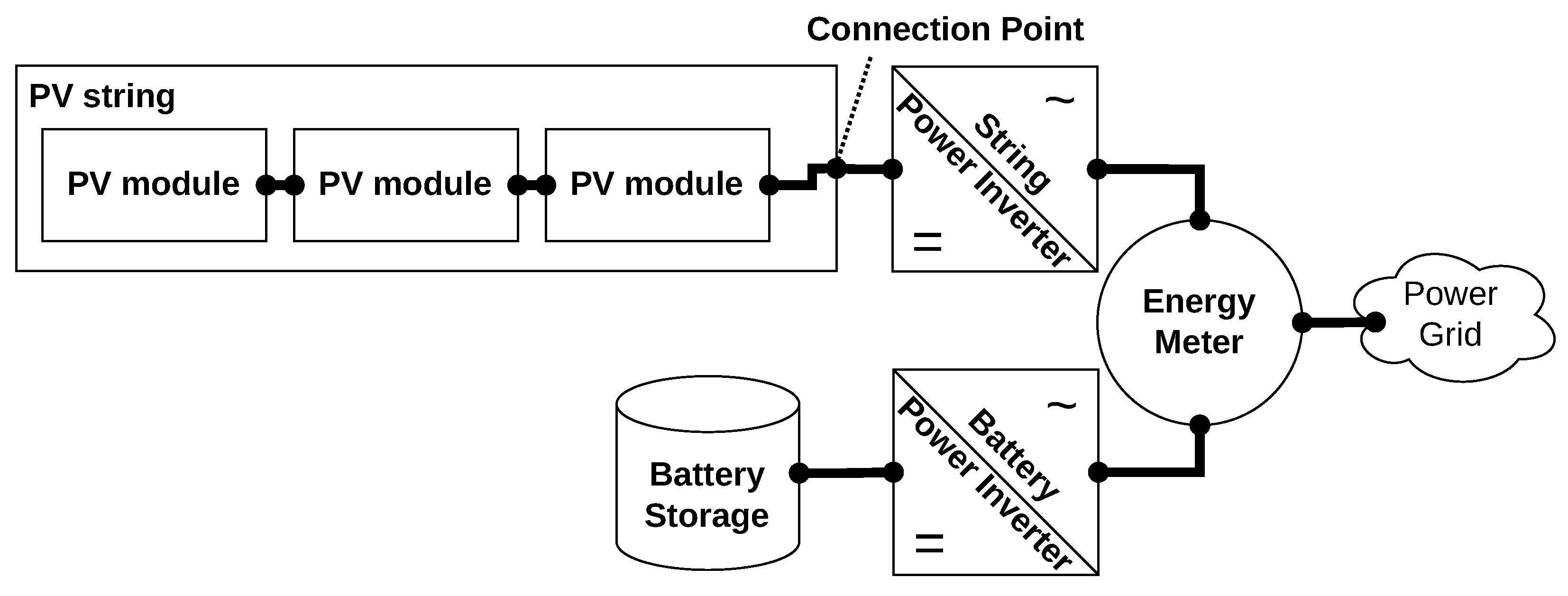
Figure 2 shows a grid-connected photovoltaic system with an independent battery storage. The system has three PV modules combined to a string. The string is connected to a power inverter which transform the direct current into alternating current and feeds the energy via an energy meter into the power grid. On the other side of the energy meter another power inverter is connected which can either leech energy from the grid to its battery storage or feed energy from the battery storage into the grid.
Figure 2 is already the structural composition data of the exemplary PV system, but to have a formal description, the PVOntology is used. Each of the components (excluding the energy meter) has master data which is described using IEC 61850 as well as a geographical position provided by the world geodetic system WGS84 that is described in GeoJSON. The master data of the energy meter and the structure of the measured data as well as the location of the measurements is described using SensorML. In the following, the PVOntology is introduced, followed by short introductions to the used standards IEC 61850, GeoJSON and SensorML. Before the concept of integrating the used standards with FDOs is explained, Research Data Collections are introduced which are used in the integration.
4.1. PV Ontology
The PVOntology shown in
Figure 3 describes the structural composition of the PV system. It defines classes and the relations between them which are found in common PV systems [
49]. The ontology consists of about twenty classes, whereupon six of them are main classes:
PhotovoltaicSystem,
SystemConcept,
SystemComponent,
Controller,
MeasurementDevice and
ConnectionPoint. All other classes are subclasses of
SystemComponent. The root node of the PV ontology graph is
PhotovoltaicSystem. It declares a complete PV system and defines four relations to four of the other five main classes. The relation
usesSystemConcept is a 1-to-1 relation stating which of the four PV system concepts defined in [
49] are used.
usesMeasuringDevice and
usesController cover the system’s instrumentation. The entry point into the structure of the photovoltaic power generation hardware is given by
composedOf. All subunits contained by this relation are instances of a subclass of
SystemComponent. These three relations are all one-to-many relations.
As mentioned before, the
SystemConcept class defines the conceptual setup of a PV system. Following [
49], there exists four concepts of photovoltaic systems:
CentralInverter,
StringInverter,
ModuleIntegratedInverter and
PowerOptimizer. The
CentralInverter concept is created by using one inverter for the whole system, all photovoltaic strings (PV modules connected in series) are connected in parallel at the single inverter. The advantage of this concept is that only one inverter is required, but through the parallel connection of the strings a mismatching loss occurs if some of the strings are shadowed (the maximum power point is averaged over all strings). To overcome the mismatching loss, each string needs to have an own inverter which can operate each string on its maximum power point. This concept is called the
StringInverter concept. In practical system implementations, often two strings with equal module count and shadowing properties are connected to one inverter. Another approach is to install an inverter onto every PV module. This leads to the
ModuleIntegratedInverter concept that allows to get the maximum power of each module, but also has a high effort in acquisition and maintenance costs. The last concept, the
PowerOptimizer, uses a so-called power optimizer for each PV module. It is a DC/DC transformer allowing to operate each module at their power maximum. These modules are connected in series to a central inverter which does the transformation of direct current to alternate current. This concept can reduce the costs of a module integrated approach by preserving the same advantages.
The classes MeasuringDevice and Controller allow to define sensors and actors belonging to the PV system instrumentation. The information recorded from a sensor can be used in plant operation like performing temperature protection of modules, tracking the sun’s position, or to make predictions, e.g., power generation predictions or replacement predictions. Of course, all kinds of sensor information may also be of interest in doing energy research or in simulations with simulated sensors which are also based on an ontology. Actors are used to control the behavior of the system like setting the maximal power output or aligning a PV system with solar tracking towards the sun. Actors may also be activated during experimental studies in research.
ConnectionPoints are used to describe the electrical interconnection of SystemComponents. A component may have one or many ConnectionPoints denoted by the object property hasConnectionPoint. A ConnectionPoint can be connectedTo another point. Using an explicit point instead of relations between components has the advantage that coupling points are specified explicitly in a electrical net. For instance, if three components are connected to each other through the same wire an approach with relation ends in a triangle situation (c1 is connected to c2, c2 is connected to c3, c3 is connected to c1). In such a triangle situation, it is not possible to determine if only one wire is used or up to three wires are used to connect them. This problem is circumvented by using an explicit coupling point.
The
SystemComponent is an abstract top class for the more specific PV system components and must be seen as a modeling-helper class only, it is the top class of all components a PV system may consists of. A
PhotovoltaicSystem is
composedOf none to many
SystemComponents, i.e., a PV system is modeled by creating a list of components which belong to the system. Therefore, the list of components only needs to include components which are not directly or indirectly referred by the
PhotovoltaicSystem class. Listing 1 shows the exemplary PV system (cf.
Figure 2) modeled with PVOntology using Turtle (
https://www.w3.org/TeamSubmission/turtle/) syntax.
| Listing 1. Excerpt of the Resource Description Framework (RDF). Description of the Exemplary PV System using Turtle Syntax. |
 |
4.2. IEC 61850 and GeoJSON
The IEC 61850 is a international standard for substation automation systems developed and maintained by the International Electrotechnical Commission (IEC) (
https://iec.ch). Primarily, it is a communication standard for information exchange between devices in a smart grid. The exchanged information is described by classes defining all relevant properties a device or facility may have. These class definitions create a set of well-defined schemas which are used in this work as models for the components of a PV system. For instance, the model of a power inverter (DINV) in IEC 61850 contains data like device ratings (e.g., maximum power output), operational limits (e.g., maximum voltage input), device properties (e.g., if the power inverter uses field effect transistors or thyristors) and more general data like vendor or model name. GeoJSON [
47] is an open standard based on the JavaScript Object Notation (JSON) file format to describe simple geographical features. It is used to model positioning information of a PV component using geographical coordinates. Both standards are used to describe the master data of a component in the PV system which is not a
MeasurementDevice. Listing 2 shows the IEC 61850 part of the master data of the PV power inverter (cf.
Figure 2) using the DINV class from the standard and Listing 3 shows the corresponding GeoJSON part.
| Listing 2. Excerpt of the Power Inverter’s Master Data using IEC 61850’s DINV Class. |
 |
| Listing 3. GeoJSON of the Power Inverter’s Master Data. |
 |
4.3. SensorML
SensorML is a standard developed by the Open Geospatial Consortium (OGC) (
http://www.opengeospatial.org/) to describe sensors and measurement processes [
48]. In this concept it is used to describe the sensor, its measurements, the data structure of the measurements and the location where the measurements can be retrieved from. Moreover, it allows to specify the geo-location of a sensor; therefore, GeoJSON is not needed. For future work, it will be considered to use only GeoJSON for localization, so that information of the same kind is described in one standard. Listing 4 shows an excerpt of the description of a sensor sitting in the same casing as the above mentioned power inverter and measures the outgoing power and other electrical quantities.
4.4. Research Data Collections
When reading the RDA recommendations on the Kernel Information Profile, it is noticeable that there is no possibility to bundle multiple data into one record. For this purpose, the RDA has proposed another recommendation—the Research Data Collection [
50]. Collections allow to bundle digital objects to reference them at once. The items of a collection do not need to be FDOs, but FDOs are valid collection items. In this concept collections are used every time information about the PV system is not, for whatever reason, available as FDO.
4.5. Integrating Structural Composition Data and Master Data with FDOs
At this point the model of the exemplary PV system is a set of decoupled objects using four different schema domains: the master data objects (IEC61850, GeoJSON, SensorML) of the components and the structural composition data object (PVOntology). It is now required to combine these objects to a coherent model by connecting the master data objects to their corresponding entity in the structural composition data object.
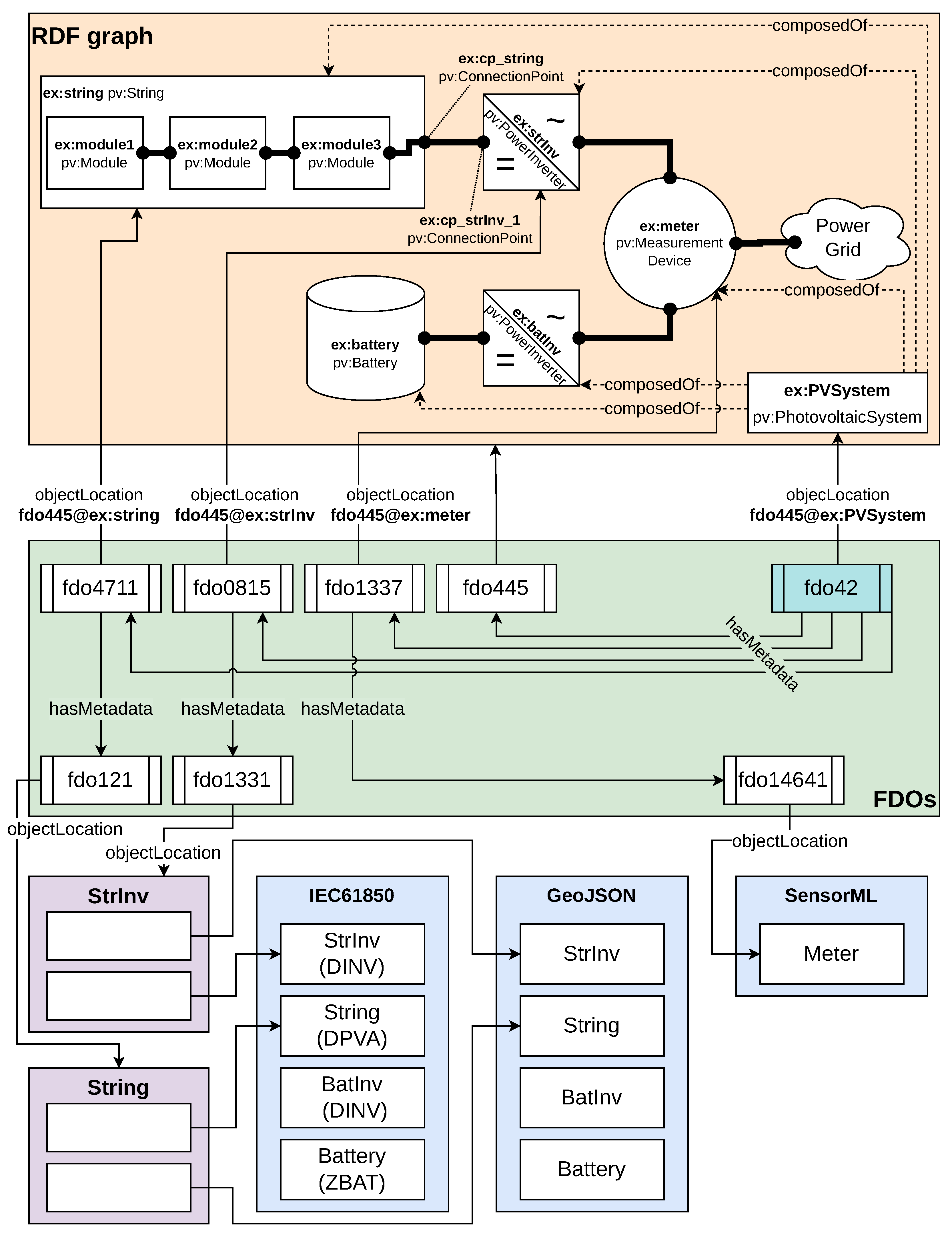
Figure 4 shows the instantiated novel concept of the exemplary PV system. The background color of the rectangles are used to distinguish between four logical layers: the yellow layer (labeled RDF graph) contains the instance graph of the PV system—the structural composition data; the green layer (labeled FDOs) contains the FDOs connecting the decoupled objects; the blue layer (each labeled with the name of a standard) contains the master data and the violet layer indicates Research Data Collection instances.
| Listing 4. Excerpt of the Sensor’s Master Data using SensorML. |
 |
To create the model, FDO
fdo445 needs to be created first. This object points with its
digitalObjectLocation attribute to the structural composition data object containing the RDF graph of the PV system instance. The
digitalObjectType indicates that the actual data is an RDF graph using the PVOntology and formatted using Turtle syntax. With this FDO the structural composition data of the PV system can be referenced. To connect, e.g., the power inverter’s master data with its corresponding node in the RDF graph, the FDO
fdo0815 needs to be created. It points with its
digitalObjectLocation into the RDF graph. This is done indirectly by referencing
fdo445 to get to the RDF graph and using a fragment identifier (delimited by the @ character) ex:strInv to reference the node in the graph. The
digitalObjectType of
fdo0815 states that it is a power inverter of a photovoltaic system. With the attribute
hasMetadata pointing to
fdo1331, it tells a user that more information about this power inverter can be found in the referenced FDO
fdo1331.
fdo1331 states with its
digitalObjectType attribute that its data is of type Research Data Collection and with the
digitalObjectLocation it points to the location of the collection. This collection bundles all master data of the power inverter into an information package. The items of the collection are pointing to the concrete master data objects (in
Figure 4 the collection contains the items pointing to the objects: StrInv (DINV) of the IEC 61850 standard and StrInv of the GeoJSON standard). This approach can be applied to all other nodes of the RDF graph for which master data objects exists that need to be connected to a graph node. The data of the PV string ex:string is organized analogous as well as the data of the energy meter ex:meter with one exception.
fdo14641 does not point to a Research Data Collection; it directly points to a master data object. This is also a valid approach, the concept does not require to use Research Data Collections at all. As explained in
Section 4.4 the
hasMetadata attribute of an FDO has cardinality 0+, which means it can be used multiple times to reference multiple other FDOs by their PID. A user needs to determine if a data object should be available as FDO, e.g., if the data object needs to be referenced in a publication, or if a collection is used. The advantage of a collection is that only one FDO is needed to make the collection referenceable; the items of the collection do not have to be FDOs themselves (but can be FDOs).
To make the whole PV system referenceable, a single PID is required. This can be done by creating a further FDO
fdo42 (cf.
Figure 4). This FDO points with its location attribute to the photovoltaic system top node of the RDF graph, stating that the FDO is this concrete photovoltaic system from the graph. The
digitalObjectType of the FDO states that it is a photovoltaic system and the
hasMetadata attribute is specified multiple times referencing all FDOs of the components of the PV system as well as
fdo445 which points to the RDF graph.
fdo42 acts as the root node into the FDO model tree from which any information about the PV system can be accessed.
5. Generalization and Limitations
The key element of the concept is the creation of an FDO as a digital representative of a physical object. The datatype of the FDO states the type of physical object, the assigned PID makes the object referenceable. Using the hasMetadata respectively isMetadataFor field of the HMC KIP metadata can be attached to the object describing the object in detail. Through the loose linking, i.e., the mentioned fields do not enforce any specific kinds of metadata, arbitrary metadata can be added which allows descriptions of different aspects of the object. Further, the usage of fragment identifiers in the digitalObjectLocation field allows to precisely state which object the FDO is about through referencing a specific entity in one or more metadata descriptions. This is helpful at least when an object consists of sub objects. The description of a sub object is done the same way as for an object. An object becomes a sub object by being linked to another object using hasMetadata respectively isMetadataFor. This linking induces an object graph. Since the concept for describing a sub object stays the same, the same logic can be used to find information while traversing the object graph. A further advantage is that it is easy to add more metadata to an (sub) object without touching other FDOs than the one which is extended. Of course it is up to the modeler which granularity (number of FDOs) is sufficient for the intended purpose.
In general, the concept is applicable at least to every technical system which consists of one or more objects or components.
A disadvantage of the concept is the high number of FDOs that are required to describe big systems in detail. This leads to a lot of links that must be resolved to find an object and its related description if the object’s PID is not known in advance.
6. Implementation
In order to show the applicability of the concept, the use case described in
Section 4 is implemented—creating an information system application to visualize a PV system and allowing a user to interactively explore the data of the system. As exemplary PV systen, the respective PV system on the rooftop of the authors’ institute is considered. The implementation is split into two parts, the data gathering and storing part, and the conceptualizing and programming part of the actual application.
The data are gathered by reading the documentation and product information papers as well as interviewing the operators of the PV system. Then the data are categorized into the three categories described in
Section 4 and stored as schema-conform data objects using JSON file format. To be able to create the FDOs, data types for different components of the PV system and the used schemas need to be defined. Therefore, the data type registry test instance (
http://dtr-test.pidconsortium.eu) of the GWDG (
https://www.gwdg.de) is used. A data type registry is a central database for data types providing machine and human-readable definitions as required in [
16]. Having the data types setup, a script is developed which allows to semi-automatically create FDOs for all the data objects. FDOs and data objects are stored in the
Metastore ([
51]) a database developed in the HMC project. This database allows storing schemas and instances in one place, validating each instance to conform to its associated schema before it is stored. The Metastore has a modern Representational State Transfer (REST) interface to retrieve and manipulate stored objects.
The visualization application is developed as a web application using the modern JavaScript framework React (
https://reactjs.org/). Moreover, the application is implemented as a plugin for the
FDO Browser. This browser, which originated from an idea of the authors to interactively explore the contents and interconnectedness of an FDO, offers a convenient programming interface for resolving, parsing and managing FDOs and a plugin interface to visualize and explore the data referenced by the FDO. The plugin selection is based on the
digitalObjectType property of an FDO. A plugin is assigned to one or more data types. Entering a PID of an FDO in the browser initiates the browser to resolve the given PID, receiving the properties of the FDO and parsing them into an internal class representation. This procedure is transparent to the user, the user only sees a loading animation which changes to a horizontal split view after successful processing.
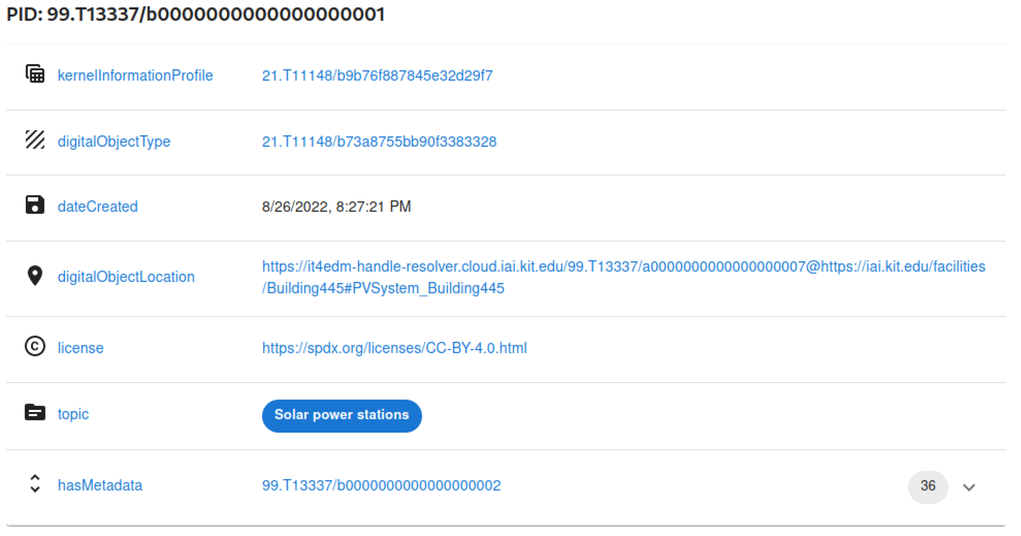
Figure 5 shows a table listing all the properties of an FDO. The table is located in the upper part of the horizontal split view. The lower part of the split view is used to present the visual output of the plugins and is referred to as plugin view. If multiple plugins are assigned to a data type, the plugin view offers the user a selection box.
For the implementation, five plugins are required: four plugins which visualize the data of the four schemas used in this concept (PVOntology, IEC 61850, GeoJSON and SensorML) and an additional plugin (FDOBridge Plugin) responsible for navigating in the FDO induced object graph, i.e., finding the data about a specific PV component. The following sections summarize the implementation and describe essential features of the plugins PVOntology, IEC 61850, SensorML and FDO Bridge. A plugin for GeoJSON has not been developed yet.
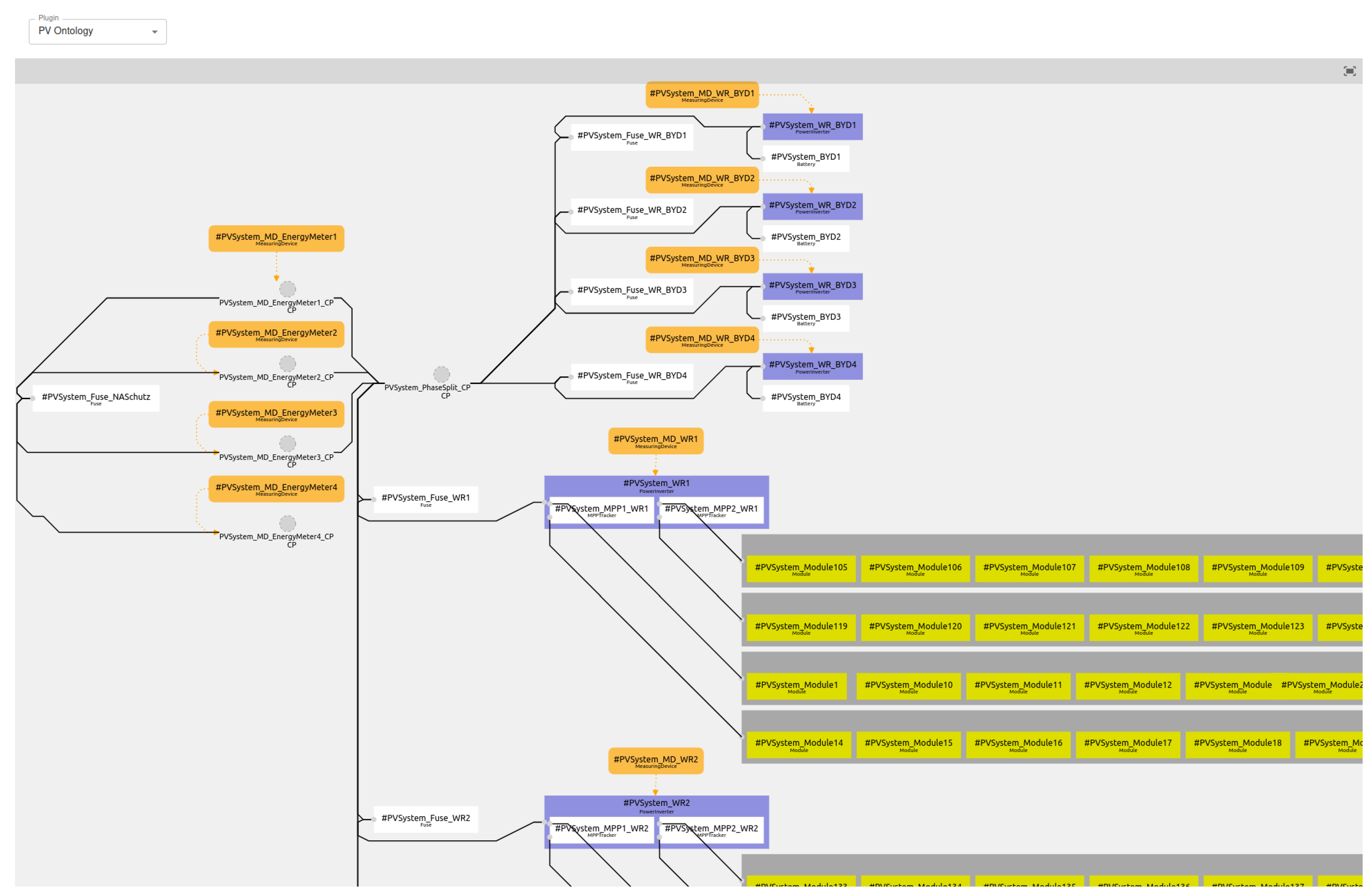
6.1. PVOntology Plugin
The PVOntology Plugin has the task to create a visualization of an arbitrary RDF graph which is created using the PVOntology ontology. Of course only the terms and relations contained in the ontology are visualized.
Figure 6 shows a screenshot of the visualization of the institutes PV system created by the plugin. To load the plugin, the calling process passes the graph instance to the constructor. Then the plugin parses the graph data and transforms it into the representation required by the used diagramming library. The transformation process maps each used component to a Scalable Vector Graphic (SVG) based representation. The size of the graphical representation and the position in the diagram is determined by a callback function. This function is called for each component. As parameter, the Uniform Resource Identifier (URI) of the component (i.e., the RDF identifier) is passed and as return value a GeoJSON object is expected containing size and position of the corresponding component. If size and/or position are not given, a default value for the size is used and the position is determined by the diagramming library built-in layout algorithm. After the transformation process, the PV system is visualized as an interactive SVG graphic that allows to zoom and pan using a mouse-like input device. To react to user mouse-click events, another callback function can be provided. This function takes as parameter the URI of the component and has no return value. The FDOBridge Plugin uses this callback to recognize in which component the user is interested and loads the metadata associated with this component.
6.2. IEC 61850 Plugin
The IEC 61850 Plugin is designed as a table that concisely presents the information from the IEC 61850 classes. The table headers are created from the corresponding schema of each class. The calling process passes an IEC 61850 schema-conform object to the plugin; the object is parsed and information is extracted in a human-readable way.
Figure 7 shows a screenshot of the visualized master data of a power inverter.
One challenge is to recognize to which class an object belongs, since in this work the standard is not used as intended as hierarchical stacked objects. Instead, the classes are used standalone to describe a specific aspect of a PV component. There are three approaches to identify the class of an object: the object states its class by itself, an algorithm analyzes the structure of the data and estimates suitable classes, or the information is passed as an additional argument. The authors chose the first approach since it is easy to implement and has less drawbacks than the other ones, as elaborated in the following: Using the second approach has a huge time overhead, although in this case an algorithm could use the schemas to find the best fitting class. It would have to examine more than 500 IEC 61850 classes. Further, it would be possible to reduce the search space, and thus directly the time consumption, by providing only a subset of classes which are relevant for this use case, i.e., only classes required for PV systems, but this would restrict the usage of the plugin to just this use case. The third approach could be realized by either creating a data type for each class of IEC 61850 or the data source, where the data object is retrieved from, must provide additional information. In the former case, it would be required to copy the class names of the whole IEC 61850 into a data type registry which creates a problem of responsibility regarding curation. In the latter case, the interface to the data source must be known by the retrieving process to be able to parse the additional information.
6.3. SensorML Plugin
As described in
Section 4.3, SensorML allows to model every aspect of a sensor. To visualize every aspect of a sensor in a suitable way is a software project of its own. Therefore, the plugin is restricted to only visualize the measurement data of a sensor as line graphs. Moreover, it is assumed that the interface of the web service, where the measurement data can be retrieved, follows the interface specifications of the institutes internal time series services as described in [
52]. With this restriction and assumption, creating the plugin is pretty straight-forward. The calling process passes an object conforming to the SensorML specification to the plugin. The plugin analyzes the object and extracts the information about the structure of the measurement data and its location. Then a request for the measurement data of the last 24 h is made. The plugin presents the user a selection of the measurement fields contained in the response. The user selects one or more measurement fields. The selected measurement fields are visualized as line chart.
Figure 8 shows the visualized measurements of the power production and the grid frequency of a power inverter of the PV system.
6.4. FDOBridge Plugin
The FDOBridge Plugin can be seen as the controller in a Model View Controller (MVC) architecture. FDOs and schema instances are the models in this architecture, and the plugins described above are the views. To initialize the plugin, a BridgeFDO and a Plugin Loader object are provided from the calling process. The given BridgeFDO induces a subgraph of the FDO induced object graph. First, the plugin examines the referenced FDOs in the hasMetadata field of the given BridgeFDO. If only BridgeFDOs are referenced, they will be listed and the user may explore them by opening them in the FDO browser. This case only occurs if the given BridgeFDO is the root node of the FDO graph and no non-BridgeFDO are referenced. If a non-BridgeFDO is found, it is passed to the Plugin Loader to obtain a suitable plugin. It is possible that more than one non-BridgeFDOs are referenced. Then the user needs to be asked which of these FDOs shall be loaded using a plugin.
The FDOBridge Plugin registers a callback on the loaded plugin. The callback is called by the loaded plugin (if the plugin supports this) each time the user interacts with a visualization element. For instance, if the loaded plugin is the PVOntology Plugin as shown in
Figure 6, the callback is called every time a user clicks on a component. As parameters the callback receives an identifier and expects a list of plugin suggestions as return value. The FDOBridge Plugin treats this identifier as a fragment identifier and searches for a match in the
digitalObjectLocation field of each referenced BridgeFDO. If a matching BridgeFDO is found, the FDOBridge Plugin traverses the subgraph, induced by the matching BridgeFDO, to resolve all referenced non-BridgeFDOs and creates a list of plugin suggestions using the Plugin Loader. A plugin suggestion is an intermediate object that allows to defer the initialization of a plugin. The plugin, which triggered the callback execution, decides based on the plugin suggestions which further plugin for the user interaction should be initialized. During the callback phase, the FDOBridge Plugin acts as MVC controller fetching models (data) and passes them to appropriate views.
7. Conclusions and Outlook
In this paper, a novel concept for metadata modeling in energy data management is presented. It combines ontologies and other metadata standards with FAIR Digital Objects (FDOs). The integration of these technologies is applied to a PV system. Several existing PV ontologies are examined and for various reasons none of these approaches do fully comply with the new concept. Therefore, a custom PV ontology is developed and presented in this work. After the first step in developing a new PV ontology, combining it with a weather ontology will be one of the next steps to be taken, especially since the example PV system treated in this paper is equipped with a weather station. Therefore, Ref. [
53] shall be mentioned here as a candidate for quickly extending the new PV ontology.
In
Section 6 a reference implementation is described and implemented using the PV information system use case from
Section 4. It should be noted that the reference implementation does not yet support Research Data Collections [
50]. In future work, collection support will be implemented using [
54] which is developed within HMC. We plan to implement the presented concept also with other tools, like an in-house development using RDF technology [
55] or a microservice-based approach as described in [
52]. A third candidate is an electronic lab notebook allowing to use arbitrary schemas models [
56]. Afterwards, it will be evaluated which implementation will work best for our data management purposes.
Since the ontologies and standards built into the concept are agnostically interchangeable, this concept is explicitly designed for application to any other energy system and even non-energy systems. It remains to a next step to demonstrate the general applicability.
On the methodological level, further work on the PV ontology is planned. With the experience and results from the self-developed ontologies, weaknesses could be identified, which will be improved in a next step. In order not to develop another ontology in a niche, it would be favorable to integrate the PV ontology with an existing greater ontology project. Because the authors are involved in a cooperation with partners from the Open Energy Ontology [
30], it is planned to integrate the PV ontology into OEO.
Author Contributions
Conceptualization, J.S. and K.-U.S.; Methodology, J.S. and K.-U.S.; Software, J.S.; Validation, J.S.; Investigation, J.S. and K.-U.S.; Resources, W.S. and V.H.; Data Curation, J.S.; Writing—original draft preparation, J.S., K.-U.S. and W.S.; Writing—review and editing, J.S., K.-U.S., W.S. and V.H.; Visualization, J.S. and K.-U.S.; Supervision, W.S. and V.H.; Project Administration, W.S. All authors have read and agreed to the published version of the manuscript.
Funding
The APC was funded by the KIT-Publication Fund of the Karlsruhe Institute of Technology.
Data Availability Statement
The data presented in this study are available on request from the corresponding author.
Acknowledgments
This publication was supported within the Hub Energy of the Helmholtz Metadata Collaboration (HMC), an incubator-platform of the Helmholtz Association within the framework of the Information and Data Science strategic initiative.
Conflicts of Interest
The authors declare no conflict of interest.
Abbreviations
The following abbreviations are used in this manuscript:
| BFO | Multidisciplinary Digital Publishing Institute |
| CIM | Directory of open access journals |
| DOA | Three letter acronym |
| DOIP | Linear dichroism |
| FDO | FAIR Digital Object |
| HMC | Helmholtz Metadata Collaboration |
| IEC | International Electrotechnical Commission |
| JSON | JavaScript Object Notation |
| KI | Kernel Information |
| KIP | Kernel Information Profile |
| MDE | Model Driven Engineering |
| MVC | Model View Controller |
| OEO | Open Energy Ontology |
| OGC | Open Geospatial Consortium |
| OWL | Web Ontology Language |
| PID | persistent identifier |
| RDA | Research Data Alliance |
| RDF | Resource Description Framework |
| REST | Representational State Transfer |
| SVG | Scalable Vector Graphic |
| UML | Unified Modeling Language |
| URI | Uniform Resource Identifier |
References
- Palensky, P.; Dietrich, D. Demand Side Management: Demand Response, Intelligent Energy Systems, and Smart Loads. IEEE Trans. Ind. Inform. 2011, 7, 381–388. [Google Scholar] [CrossRef]
- Rehmani, M.H.; Reisslein, M.; Rachedi, A.; Erol-Kantarci, M.; Radenkovic, M. Integrating Renewable Energy Resources Into the Smart Grid: Recent Developments in Information and Communication Technologies. IEEE Trans. Ind. Inform. 2018, 14, 2814–2825. [Google Scholar] [CrossRef]
- Ansari, M.H.; Vakili, V.T.; Bahrak, B. Evaluation of big data frameworks for analysis of smart grids. J. Big Data 2019, 6, 1–14. [Google Scholar] [CrossRef]
- Uslar, M. Semantic interoperability within the power systems domain. In Proceedings of the First International Workshop on Interoperability of Heterogeneous Information Systems—IHIS ‘05, Bremen, Germany, 4 November 2005. [Google Scholar] [CrossRef]
- Wilkinson, M.D.; Dumontier, M.; Aalbersberg, I.J.J.; Appleton, G.; Axton, M.; Baak, A.; Blomberg, N.; Boiten, J.W.; da Silva Santos, L.B.; Bourne, P.E.; et al. The FAIR Guiding Principles for scientific data management and stewardship. Sci. Data 2016, 3, 160018. [Google Scholar] [CrossRef]
- Collins, S.; Genova, F.; Harrower, N.; Hodson, S.; Jones, S.; Laaksonen, L.; Mietchen, D.; Petrauskaite, R.; Wittenburg, P. Turning FAIR Data into Reality: Final Report and Action Plan from the European Commission Expert Group on FAIR Data; Publications Office of the European Union: Luxembourg, 2018. [Google Scholar]
- Kahn, R.; Wilensky, R. A framework for distributed digital object services. Int. J. Digit. Libr. 2006, 6, 115–123. [Google Scholar] [CrossRef]
- DONA Foundation. Digital Object Interface Protocol Specification; DONA Foundation: Guwahati, India, 2018. [Google Scholar]
- Wittenburg, P. GEDE—Digital Object Topic Group Report. 2019. Available online: https://github.com/GEDE-RDA-Europe/GEDE/blob/master/Digital-Objects/Foundation-Documents/DOTerminology.pdf (accessed on 9 August 2021).
- Schultes, E.; Gregory, A.; Magagna, B. Emerging FAIR Ecosystem(s): A Practical Perspective. Res. Ideas Outcomes 2022, 8, e94149. [Google Scholar] [CrossRef]
- Schultes, E.; Wittenburg, P. FAIR Principles and Digital Objects: Accelerating Convergence on a Data Infrastructure. In Proceedings of the Data Analytics and Management in Data Intensive Domains; Manolopoulos, Y., Stupnikov, S., Eds.; Springer International Publishing: Berlin/Heidelberg, Germany, 2019; pp. 3–16. [Google Scholar]
- Jacobsen, A.; de Miranda Azevedo, R.; Juty, N.; Batista, D.; Coles, S.; Cornet, R.; Courtot, M.; Crosas, M.; Dumontier, M.; Evelo, C.T.; et al. FAIR Principles: Interpretations and Implementation Considerations. Data Intell. 2020, 2, 10–29. [Google Scholar] [CrossRef]
- Benhamed, O.M.; Burger, K.; Kaliyaperumal, R.; da Silva Santos, L.O.B.; Suchánek, M.; Slifka, J.; Wilkinson, M.D. The FAIR Data Point: Interfaces and Tooling. Data Intell. 2022, 1–18. [Google Scholar] [CrossRef]
- Anders, I.; Blanchi, C.; Broeder, D.; Hellström, M.; Islam, S.; Jejkal, T.; Lannom, L.; Peters, K.; Quick, R.; Schlemmer, A.; et al. FAIR Digital Object Specifications Version PR 1.2: FDO Forum Proposed Recommendation; FAIR Digital Objects Forum: Leiden, The Netherlands, 2022. [Google Scholar]
- De Smedt, K.; Koureas, D.; Wittenburg, P. FAIR Digital Objects for Science—From Data Pieces to Actionable Knowledge Units. Publications 2020, 8, 21. [Google Scholar] [CrossRef]
- Weigel, T.; Plale, B.; Parsons, M.; Zhou, G.; Luo, Y.; Schwardmann, U.; Quick, R.; Hellström, M.; Kurakawa, K. RDA Recommendation on PID Kernel Information: Version 1; RDA: Yokohama, Japan, 2018. [Google Scholar]
- Pfeil, A.; Jejkal, T.; Schweikert, J.; Pirogov, A.; Videgain Barranco, P.; Krebs, F.; Koch, C.; Günther, G.; Curdt, C.; Weinelt, M. Helmholtz Kernel Information Profile; Technical Report; Helmholtz Metadata Collaboration: Helmholtz, Germany, 2023. [Google Scholar]
- Gruber, T.R. A translation approach to portable ontology specifications. Knowl. Acquis. 1993, 5, 199–220. [Google Scholar] [CrossRef]
- Chandrasekaran, B.; Josephson, J.R.; Benjamins, V.R. What Are Ontologies, and Why Do We Need Them? IEEE Intell. Syst. 1999, 14, 20–26. [Google Scholar] [CrossRef]
- Euzenat, J.; Shvaiko, P. Ontology Matching; Springer: Berlin/Heidelberg, Germany, 2013. [Google Scholar] [CrossRef]
- Guarino, N.; Oberle, D.; Staab, S. What Is an Ontology? In Handbook on Ontologies; Staab, S., Studer, R., Eds.; Springer: Berlin/Heidelberg, Germany, 2009; pp. 1–17. [Google Scholar] [CrossRef]
- Oberle, D. How ontologies benefit enterprise applications. Semant. Web 2009, 5, 473–491. [Google Scholar] [CrossRef]
- Gasevic, D.; Devedsic, V.; Djuric, D. Model Driven Engineering and Ontology Development; Springer: Berlin/Heidelberg, Germany, 2009. [Google Scholar] [CrossRef]
- Guarino, N.; Giaretta, P. Ontologies and knowledge bases—Towards a terminological clarification. In Towards Very Large Knowledge Bases; Mars, N.J.I., Ed.; IOS Press: Ohmsha, Japan, 1995; pp. 25–32. [Google Scholar]
- Bennett, M.; Baclawski, K. The role of ontologies in Linked Data, Big Data and Semantic Web applications: Editorial. Appl. Ontol. 2017, 12, 189–194. [Google Scholar] [CrossRef]
- Uschold, M. Knowledge level modelling - Concepts and terminology. Knowl. Eng. Rev. 1998, 13, 5–29. [Google Scholar] [CrossRef]
- Jarrar, M.; Demey, J.; Meersman, R. On Using Conceptual Data Modeling for Ontology Engineering. J. Data Semant. I 2003, 2800, 185–207. [Google Scholar]
- Noy, N.F.; Klein, M. Ontology Evolution: Not the Same as Schema Evolution. Knowl. Inf. Syst. 2004, 6, 428–440. [Google Scholar] [CrossRef]
- Kogalovsky, M.R.; Kalinichenko, L.A. Conceptual and ontological modeling in information systems. Program. Comput. Softw. 2009, 35, 241–256. [Google Scholar] [CrossRef]
- Booshehri, M.; Emele, L.; Flügel, S.; Förster, H.; Frey, J.; Frey, U.; Glauer, M.; Hastings, J.; Hofmann, C.; Hoyer-Klick, C.; et al. Introducing the Open Energy Ontology: Enhancing data interpretation and interfacing in energy systems analysis. Energy AI 2021, 5, 100074. [Google Scholar] [CrossRef]
- Smith, B. Basic Formal Ontology 2.0—Specification and User’s Guide; MIT Press: Cambridge, MA, USA, 2015. [Google Scholar]
- Kücük, D.; Kücük, D. OntoWind—An Improved and Extended Wind Energy Ontology. arXiv 2018, arXiv:1803.02808. [Google Scholar]
- Piazza, A.; Faso, G. Concentrated Solar Power: Ontologies for Solar Radiation Modeling and Forecasting. In Advances onto the Internet of Things; Advances in Intelligent Systems and Computing; Gaglio, S., Lo Re, G., Eds.; Springer: Cham, Switzerland, 2014; Volume 260, pp. 325–337. [Google Scholar] [CrossRef]
- Kantamneni, A.; Brown, L.E. An Ontology for Solar Irradiation Forecast Models. In Proceedings of the 10th International Joint Conference on Knowledge Discovery, Knowledge Engineering and Knowledge Management, Seville, Spain, 18–20 September 2018; pp. 263–270. [Google Scholar] [CrossRef]
- Wang, M.H.; Tsai, Y.T.; Lin, K.H.; Lee, C.S.; Liu, C.H. FML-based decision support system for solar energy supply and demand analysis. In Proceedings of the 2013 IEEE International Conference on Fuzzy Systems (FUZZ-IEEE), Hyderabad, India, 7–10 July 2013; pp. 1–8. [Google Scholar] [CrossRef]
- Dagnely, P.; Tsiporkova, E.; Tourwe, T.; Ruette, T.; de Brabandere, K.; Assiandi, F. A semantic model of events for integrating photovoltaic monitoring data. In Proceedings of the 2015 IEEE 13th International Conference on Industrial Informatics (INDIN), Cambridge, UK, 22–24 July 2015; pp. 24–30. [Google Scholar] [CrossRef]
- Khosrojerdi, F.; Gagnon, S.; Valverde, R. Proposing an Ontology Model for Planning Photovoltaic Systems. Mach. Learn. Knowl. Extr. 2021, 3, 582–600. [Google Scholar] [CrossRef]
- McMorran, A.W.; Ault, G.W.; Morgan, C.; Elders, I.M.; McDonald, J.R. A Common Information Model (CIM) Toolkit Framework Implemented in Java. IEEE Trans. Power Syst. 2006, 21, 194–201. [Google Scholar] [CrossRef]
- Ding, M.; Zhang, Z.; Guo, X. CIM Extension of Microgrid Energy Management System. In Proceedings of the Asia-Pacific Power and Energy Engineering Conference, Wuhan, China, 28–30 March 2009; pp. 1–6. [Google Scholar] [CrossRef]
- Kim, H.J.; Jeong, C.M.; Sohn, J.M.; Joo, J.Y.; Donde, V.; Ko, Y.; Yoon, Y.T. A Comprehensive Review of Practical Issues for Interoperability Using the Common Information Model in Smart Grids. Energies 2020, 13, 1435. [Google Scholar] [CrossRef]
- Tah, J.H.; Abanda, H.F. Sustainable building technology knowledge representation: Using Semantic Web techniques. Adv. Eng. Inform. 2011, 25, 547–558. [Google Scholar] [CrossRef]
- Abanda, F.H.; Tah, J.; Duce, D. PV-TONS: A photovoltaic technology ontology system for the design of PV-systems. Eng. Appl. Artif. Intell. 2013, 26, 1399–1412. [Google Scholar] [CrossRef]
- Lefrançois, M.; Kalaoja, J.; Ghariani, T.; Zimmermann, A. SEAS Knowledge Model. In Deliverable 2.2, ITEA2 12004 Smart Energy Aware Systems; ITEA Organisation: Eindhoven, The Netherlands, 2016; 76p. [Google Scholar]
- Kogalovsky, M.R. Metadata in computer systems. Program. Comput. Softw. 2013, 39, 182–193. [Google Scholar] [CrossRef]
- Lebo, T.; Sahoo, S.; McGuiness, D. PROV-O: The PROV Ontology; W3C: Cambridge, MA, USA, 2013. [Google Scholar]
- Mackiewicz, R.E. Overview of IEC 61850 and Benefits. In Proceedings of the 2006 IEEE PES Power Systems Conference and Exposition, Atlanta, GA, USA, 29 October–1 November 2006; pp. 623–630. [Google Scholar] [CrossRef]
- Dorman, M. Introduction to Web Mapping; Chapman and Hall/CRC: Boca Raton, FL, USA, 2020; Chapter 7. [Google Scholar] [CrossRef]
- Botts, M.; Robin, A.; Hirschhorn, E. OGC SensorML: Model and XML Encoding Standard; OGC: Rockville, MD, USA, 2020. [Google Scholar]
- Mertens, K. Photovoltaik; Carl Hanser Verlag GmbH & Co. KG: Munich, Germany, 2020. [Google Scholar] [CrossRef]
- Weigel, T.; Almas, B.; Baumgardt, F.; Zastrow, T.; Schwardmann, U.; Hellström, M.; Quinteros, J.; Fleischer, D. Recommendation on Research Data Collections; Technical Report; Research Data Alliance: London, UK, 2017. [Google Scholar] [CrossRef]
- Hartmann, V.; Jejkal, T.; Stotzka, R. Metastore—Enable FAIR Metadata Documents; KIT: Karlsruhe, Germany, 2021. [Google Scholar] [CrossRef]
- Braun, E.; Schlachter, T.; Düpmeier, C.; Stucky, K.U.; Suess, W. A Generic Microservice Architecture for Environmental Data Management. In Environmental Software Systems. Computer Science for Environmental Protection; Springer International Publishing: Berlin/Heidelberg, Germany, 2017; pp. 383–394. [Google Scholar] [CrossRef]
- Staroch, P. A Weather Ontology for Predictive Control in Smart Homes; Diplomarbeit;Technischen Universität Wien: Wien, Austria, 2013. [Google Scholar]
- Jejkal, T.; Chelbi, S.; Pfeil, A. RDA Collection Registry Adoption; KITopen: Karlsruhe, Germany, 2021. [Google Scholar] [CrossRef]
- Schumilin, A.; Stucky, K.U.; Sinn, F.; Hagenmeyer, V. Towards ontology-based network model management and data integration for smart grids. In Proceedings of the 2017 Workshop on Modeling and Simulation of Cyber-Physical Energy Systems (MSCPES), Pittsburgh, PA, USA, 21 April 2017. [Google Scholar] [CrossRef]
- Brandt, N.; Griem, L.; Herrmann, C.; Schoof, E.; Tosato, G.; Zhao, Y.; Zschumme, P.; Selzer, M. Kadi4Mat: A Research Data Infrastructure for Materials Science. Data Sci. J. 2021, 20. [Google Scholar] [CrossRef]
| Disclaimer/Publisher’s Note: The statements, opinions and data contained in all publications are solely those of the individual author(s) and contributor(s) and not of MDPI and/or the editor(s). MDPI and/or the editor(s) disclaim responsibility for any injury to people or property resulting from any ideas, methods, instructions or products referred to in the content. |
© 2023 by the authors. Licensee MDPI, Basel, Switzerland. This article is an open access article distributed under the terms and conditions of the Creative Commons Attribution (CC BY) license (https://creativecommons.org/licenses/by/4.0/).


