3. Research on Improving Performance of LHTESS through Introducing Inserts/Fins/Structures with High Thermal Conductivity
Improvement of performance of LHTESS, through the addition of extended surfaces or fins with high TC and various geometric configurations, is widely practiced. In accommodating direct contact of the PCM with high TC fins and the active heat transfer surfaces, the main goal is to remove the shortcomings related to the weak TC of PCM. In addition, diffusive and convective heat transport within the PCM that are realized without these fins are extremely important. Through modifying heat transport in logically re-designed TES systems, charge/discharge characteristics of such units should be improved at the expense of a smaller amount of PCM and generally heavier weight of the system.
According to [
17], introducing fins into PCM was practiced as early as 1966. Numerous studies were performed since then to investigate the consequences of using fins on melting and solidification. Many of these studies are discussed in this review, serving as an update to [
17]. After providing a chronological review of the targeted papers, their highlights will be provided in a tabular form. Classification of these papers will then follow in a tabular form. Combining reviews of relevant papers in this document and those of [
16,
17], which provided reviews/classifications of 75 fin-assisted latent heat thermal energy storage systems, researchers will have access to comprehensive reviews of 206 papers reported since 1966. The cumulative frequency of the pre-2016 publications (
Figure 1) suggests uninterrupted ongoing interest in the topic of this review article.
Ismail et al. [
20] investigated solidification and melting of a PCM (paraffin and sulfur) filled in a tube-in-tank setup experimentally. A transparent cuboid tank was located at the center of a bigger insulated cuboid with a hot working fluid maintained at the
Tm of the PCM circulating through the spacing between these two tanks. Vertical tubes with circular and square cross sections that were fitted with four ES plate longitudinal fins (LF) attached to the outer surface of the tubes were inserted at the middle of the smaller tank. The heat transfer fluid (HTF), silicone, was introduced through an inner circular tube at the top of the vertical tubes and was then extracted at an outlet port on the periphery of the vertical tubes. The PCM was filled into the space between the smaller cuboid tank and the finned tube. Circulation of cold or hot HTFs within the vertical tubes triggered freezing or melting of the PCM. A lifting mechanism was installed on the top of the setup which was used for raising the finned tube during the experiment in order to measure the instantaneous thickness of the frozen layer. The development of the solidified layer was also measured using a camera system, and also a technique employing recorded temperatures. The varied frozen layers with respect to time for both circular and square tube cases were presented. Thickness of the fin did not have major effects on the phase transition process, and further suggested that a greater number of fins tend to promote the heat transfer rate and solidification rate. Without showing results, it was mentioned that the improvement of heat transfer was less marked with the number of fins increasing beyond six. A greater number of fins led to suppression of convection currents within the molten PCM and decreased storage capacity. Higher ratio of the inner hydraulic diameter over the outer hydraulic diameter of the tanks and greater fin height were observed to lead to acceleration of solidification, whereas the higher ratio of hydraulic diameters resulted in suppression of the convective currents.
Ismail and Alves [
21] performed both numerical and experimental analyses of solidification of eicosane around one of a staggered array of LF tubes within an LHTES unit, with the HTF passing inside the tubes. Increased fin height, greater value of the number of fins, lowered compactness ratio and higher degree of superheating (the difference between
Tm and wall temperature) were observed to lead to reduced freezing time, and the effects of the fin thickness on the freezing time was negligible. Positions of the experimental and numerical liquid–solid interface (LSI) agreed well. Differences between the two approaches in the case of long fins can be explained by the inappropriate use of a linear approximation of the temperature gradient due to the big inclination of the LSI near the fins. Differences between the two approaches at later instants were due to ignorance of the increased heat transfer area resulting from the motion of the dendrites near the LSI, which increased the solidification rate. The emergence of the dendrites accounted for the domination of conduction during solidification, and the adoption of fins were observed to suppress convection and speed up the heat transfer rate.
Ho and Viskanta [
22] experimentally investigated the thermal performance of n-Octadecane in a cavity (copper bottom plate, two aluminum vertical walls and two vertical Plexiglas
® windows) during melting and freezing realized by circulating HTF through channels in the copper plate. Degassed liquid PCM was syphoned into the chamber such that there was an air gap above the PCM. Profiles of the LSI were recorded photographically. Conduction was the dominant heat transfer mechanism at the early stage of melting, whereas density-induced melt motion forced the liquid to overflow above the unmelted part. Wavy-shaped LSI appeared below the solid core due to unsteady vortex circulation. A thicker melt layer was observed at the top, where melting was faster due to natural convection. Empirical correlation of the molten fraction with respect to dimensionless time was obtained, showing that subcooling of PCM could delay melting because part of the energy was transferred to sensible heat to increase the temperature of the solid core, and specimens with a higher aspect ratio (
AR) were observed to induce slower melting rate. A Mach–Zehnder interferometer was introduced to determine 2-D temperature distribution and convective recirculation patterns. Convection was observed to intensify gradually based on the observed fringe lines deflection. ‘Cellular’ flow patterns appeared near the surface of heat source, but were then suppressed by intensified recirculation with the progression of melting (
Figure 2a,b). A shadowgraph technique was applied to investigate the local heat transfer coefficient. It was demonstrated that
Nuy/Ray1/4 (
Nu and
Ra, being the Nusselt and Rayleigh numbers, are measures of convective to conductive heat transfer across a boundary, and the importance of natural convection, respectively) decreased as melting continued, indicating transition from conduction-dominated melting to convection mode, whereas an opposite trend was observed with the raising of the
AR. A periodic variation of the local
Nu number along the base indicated the presence of multiple recirculating patterns. These fluctuations weakened as the melt zone became larger, resulting in decreased vortex cells. The energy balance method based on the molten volume fraction (VF) was adopted to obtain the average heat transfer data from the heated surface, due to the poor performance of the shadowgraph method at the corner of the test cell. An empirical correlation of the average
Nu as a function of the
Ra and
Ste (the Stefan number is a measure of sensible heat compared to the latent heat) numbers, in addition to the
AR and initial subcooling parameters, was presented. As for the freezing experiments, the solidified layer was initiated at the bottom, then propagated along the conducting walls. For a smaller
AR, a more uniform solidified layer with shorter walls was observed. Superheating was observed to only influence the early stage of the cooling process. Small
AR was observed to enhance the solidification rate.
Details of [
21] were reported by [
23]. For the experimental component, the HTF passed through a frame-supported vertical single tube which was placed inside the PCM contained within an insulated shell. At certain time instants, the test model was removed to measure the radial and circumferential distributions of the solidified layer. The fraction of solidified PCM, while considering the effects of fin height, number of fins, compactness ratio and degree of superheating was presented.
Okada [
24] investigated melting due to a vertical copper cylinder placed concentrically in a horizontal disk-like solid n-Octadecane initially at its
Tm that was then subjected to a step change in temperature. Thawing of the PCM, including the effect of natural convection, was studied by a finite-difference method. Positions of LSI and the temperatures along the radial direction on the mid-plane of the PCM were measured and agreed well to computational data. Variations of the
Nu on the heated cylinder and dependence of volume of the molten liquid with the
Ra and time were discussed.
Saito et al. [
25] reported on the performance of a TES unit incorporating 106 parallel vertical plate brass fins saturated with naphthalene. A single active wall of the unit was controlled by the flow of a heating oil (90–100 °C) through an oil jet box, in which the oil was directed into jets impinging on a heat transfer surface. A 2-D vorticity-stream function-based finite-difference model utilizing apparent TC and specific heat was employed for simulating the flow and thermal fields in a single PCM cell. The optimum
AR of the PCM cell that gave rise to the maximum dimensionless average heat flux was found to exist for a given combination of the Grashof number (measure of the relative importance of the buoyancy and viscous forces), Prandtl number (measure of a fluid’s diffusivities of momentum and heat) and dimensionless fin pitch.
Freezing around a circular hollow tube (inside of which an HTF was flowing) with annular fins (AF) placed on the outer surface was studied by Imura and Yoshida [
26] using a 2-D model of a single PCM cell. Among the fin’s radius, length, thickness and the
Ste parameters, the fin length exhibited the greatest variation, whereas the
Ste was observed to have little influence. In addition, a numerical approach utilizing a 1-D quasi-steady state diffusion analysis was also presented, exhibiting close comparison with the findings of the 2-D analysis. Imura and Yoshida [
27] reported on phase change within an LHTES unit consisting of a hollow horizontal circular brass tube with brass AF. Water was circulated through the hollow tube, and n-Octadecane served as the PCM. The experimental data were then compared to [
26]. During freezing, experimentally determined heat fluxes were found to be 20 percent greater than the numerical results, due to the occurrence of dendrites. The effect of the
St was found to be small, as shown earlier [
26]. For the thawing experiments, convection became more dominant in relation to conduction as the experiments progressed. Heat fluxes obtained from the experiments were far greater than the values predicted by a computational approach that ignored flow.
Melting of n-Octadecane around a horizontal rod that included four axial holes drilled into it as HTF passageways with and without LF was investigated by Betzel and Beer [
28]. The PCM was held within a thermally insulated unit and the LSI was visualized through Plexiglas
® plates. Fin materials of PVC and copper were adopted, and three LF in two patterns (Y and reversed Y) were studied. Based on instantaneous melting contours and flow patterns, convection was observed to dominate after a short time, prevailing over conduction. The heat transfer rate was observed to be marked at the top section of the PCM-filled annulus space between the fins, whereas melting progressed slowly within the space below the tube and next to lower fins. Symmetric convection cells were found along the vertical axis. Compared to the bare rode, the PCM melting rate was decreased on the top annulus sector; however, it was increased within the lower sector for PVC-fins with the Y-pattern. For the case PVC-fins with the reversed Y-pattern, the melting rate was even slower than the case with the Y-pattern. A high melting rate and a nearly isothermal liquid surface was realized with copper fins. The presence of six convection cells contributed to expedited melting rate for the Y-pattern, whereas for the reversed Y-pattern, only two convection cells were generated, resulting in a slower melting rate. Correlating the dimensionless melting rate to time, copper fins resulted in highest melting rates, whereas the PVC fins contributed to a slightly higher melting rate compared to bare rod. Y-pattern of fins led to a faster melting rate than the units with the reversed Y-pattern. Spanwise Gortler vortices (
Figure 3), detected at the concave LSI, enhanced the heat transfer rate. Correlations of the mean
Nu as a function of the
Ste and
Ra were obtained.
Okada [
29] extended [
24] by performing experimental and computational analyses of thawing around a vertical copper cylinder with or without subcooling. Measured positions of the LSI agreed well with results of the simulations. By lowering the initial temperature of the PCM below its
Tm (dimensionless subcooling factors −0.5, −1, −2 and −3), the melting rate was suppressed markedly. The subcooling factor lowered the rate of the total thermal energy storage. Dependence of the average
Nu on the surface of the heated cylinder and the average thickness of the molten liquid region were independent of the subcooling factor. Volume of the molten PCM for different cylinder diameters, for the case of no subcooling, were correlated to a dimensionless time that included the
AR of the cylinder.
The English translation of Saito et al. [
30], i.e., ref. [
31], reported results of experimental and computational studies on melting in a rectangular unit were very similar to [
25]. The unit was mounted on a platform that could be inclined. Comparing the unit to the one used by [
25], the main distinction was that the plate fins in the present study were inclined to the horizontal, whereas only vertical plate fins were studied by [
25]. It was observed that the shape of the moving solid phase varied as the PCM received heat from the surrounding walls at the contact points. A numerical method that assumed a parabolic velocity distribution in the liquid phase was developed. Results of the experiments using n-Octadecane agreed well with computational findings. The average melting rate was found to be independent of the inclination angle. However, the contacting mode and the heat flux variation on the walls were dependent on the inclination angle.
An experimental study in combination with an approximate solution to the phase transition phenomenon in an LHTES unit consisting of a horizontal circular tube through which the HTF flowed was investigated by Ito et al. [
32]. The specific PCM was n-Octadecane that surrounded the tube, which was fitted with plate AF. A dimensionless heat extraction rate, or an apparent
Bi (the Biot number is a measure of relative importance of heat transfer resistances within and at the surface of an object), as a function of a dimensionless time (obtained by analysis or experiment for the finned tube at a constant wall temperature) was utilized. Apparent performance of the thermal energy storage unit with the finned tube was analyzed, exhibiting good agreement with the experimental results.
Sasaguchi and Sakamoto [
33] focused on studying thawing in an elemental annular cylindrical region bounded by two LF and conducting inner and outer tube walls. Melting that was initiated on the heated inner tube wall depended on the orientation of the test region (φ = −90° to +90°), the angle between the two LF (α = 20° to 90°) and the temperature of the tube wall. The effects of the orientation of the elemental test region, the angle between the two fins and the temperature of the heated tube wall on the position of the evolving LSI, including the influence of convection, were discussed. Addressing limited computational findings in relation to LHTES systems having tubes with AF (radial), Sasaguchi [
34] reported on the relevant results of a new method. Moreover, the predicted performance of the units was compared with those of LHTES systems having a tube with LF and AF (radial) in addition to an unfinned tube. Melting of eicosane in an elemental annular cylindrical region bounded by two LF and conducting inner and outer tube walls was studied experimentally by Sasaguchi [
35]. Melting was controlled by an array of impinging radial jets of a hot fluid supplied from a constant-temperature bath. Thawing experiments were conducted to determine the effects of the orientation of the elemental test region (φ = −90° to +90°), the angle between the two fins (α = 20° to 90°) and the temperature of the heated tube wall. Expedited thawing next to the fins and the role of convection in promoting melting are clearly observed. Measurements of temperature of the PCM were also compared to [
33].
The appropriateness of a similarity curve for evaluating the performance of LHTES units was investigated by Kaino [
36]. A system of concentric circular tubes with LF in the annular space was analyzed the freezing process. A similarity rule was shown to be valid, as well as to an unfinned unit, while its appropriateness deteriorated with the increasing number of fins. Differences among similarity curves for various number of fins were so marked that the configuration effect can also be accounted for. Heat exchanger effectiveness was compared to existing experimental data, exhibiting good agreement. Computational studies of Kaino [
37] showed that, in a storage unit with LF undergoing freezing, the influence of the
Ste varied with the number of plate fins. Contributions of the sensible heat released within the PCM, the heat transfer tube and the fins were evaluated separately. Relation between the solidified fraction and sensible heat for the
Bi range 0.1–1000 was presented. The interplay of the latent and sensible heat was examined for various
Ste numbers, exhibiting an inverse relation. Given the existence of a similarity function varying with the frozen fraction and independent of the
Bi to be linked to uniformity of heat flux on a heat transfer surface, Kaino [
38] focused on the previously studied LHTES units featuring LF, in which such uniformity was perturbed. For a heat transfer tube made of a high TC material, the existence of such a similarity rule can be assured for a wide range of tube thicknesses. However, given a heat transfer tube with a low TC material, the similarity rule was valid only with considerably thick tube walls. Kaino [
39] extended [
38] to include the effects of thickness, TC and the number of fins. It was shown that upon reducing the thermal conductance of the fin, thickness and/or TC of the fins, the similarity rule becomes more applicable.
Phase transition within porous media saturated with a PCM contained between two parallel planar fins was studied by Sasaguchi and Takeo [
40] (English translation [
41]). Heat conduction dominated the freezing process. The effect of the orientation of the fins with the vertical direction was also investigated. Velocity vectors and isotherms at three dimensionless time instants during thawing for a case with the fins positioned in the vertical direction were discussed, and the strengthening effect of natural convection at later time instants were clearly observed. Similar behavior was observed at the other extreme with the fins being in the horizontal position.
Al-Jandal and Sayigh [
42] studied the performance of a proposed solar tube collector (STC). Experiments were performed to simulate a storage system using two vertical cylindrical concentric tubes with stearic acid filling the annular space. This instrumented set-up shared many features of earlier experimental set-ups going back to 1981 [
17], and discussed above [
20,
21,
23] and later in this paper, since the HTF was introduced within a vertical end-closed tube. In this work, the researchers also incorporated a path for another HTF to circulate on the outer shell of the unit. Experimental results corresponding to the utilization of 13 AF and 3 LF provided quantitative information concerning heat transfer and transient evolution of the LSI, pointing to the role of buoyancy-driven convection.
Choi and Kim [
43] performed a study for unfinned, circular stainless steel 5-finned and 10-finned tube systems. The experimental apparatus was composed of a vertical cylindrical Pyrex glass TES vessel and a stainless-steel double-tube, with 5 or 10 AF welded on the its outer surface, with 20 or 10 mm axial pitch. Temperatures of the five-finned-tube system were always higher than those of the unfinned-tube system. Thermal performance during melting in all three tube systems were more strongly affected by the inlet temperature than by the flow rate of the HTF. The volume of melted PCM in the 5- and 10-finned-tube systems were nearly 25% greater than the unfinned-tube, since the annular finned-tube system expedited melting and inhibited convective motion. Heat storage in the 5- and the 10-finned-tube systems were 37% and 48% greater than the unfinned-tube system, respectively. For the unfinned-tube at low molten VF, the outside heat transfer coefficient (
ho) decreased by increasing the melted volume in the region affected by conduction, while beyond this region, the melted volume increased by increasing the melted liquid VF. For the systems with fins, within the finned section,
ho decreased sharply since the presence of fins inhibited convection. On the other hand, beyond this section,
ho did not increase as much as the unfinned-tube system since the fins partially inhibited convection. In the unfinned-tube system, the heat transfer coefficient was much greater than the value calculated for steady conduction except near the tube wall. Melting from an outside wall of the convectively heated unfinned-tube was modeled. The measured melting-front velocity enhanced by increasing the
Ste and
Bi exhibited good agreement with the analytical solution. Therefore, the effect of convection on melting was negligible, and it only contributed to increasing the sensible heat of the melted liquid PCM. Choi et al. [
44] investigated the melting thermal performance of a low-temperature vertical cylindrical shell-and-tube LHTES. The HTF-carrying tube consisted of a concentric double tube, with the HTF (water) from the top inlet of the inner tube flowing downward and then re-directed in the opposite direction, flowing out through the top outlet placed at the periphery of the outer tube. A helical type silicon wire was inserted as a turbulence promoter to reduce the thermal resistance at the HTF side. Twelve equally spaced AF were attached to the outer surface of the HTF tube, and the tube’s fins and shell were all made of stainless steel. The PCM was kept at 5 °C lower than its
Tm. The rate of heat storage decreased sharply at the beginning during thawing for three types of geometries (thin-finned-tube, thick-finned-tube and unfinned-tube system) and then tended to slow down gradually. Higher inlet temperature of the HTF was observed to lead to enhanced rates of heat storage due to improved TD. The effect of the flow rate was negligible due to existence of the turbulence promoter, which made the HTF flow turbulent even at low flow rates. The thick-finned-tube exhibited 70% greater heat storage compared to the unfinned-tube system, whereas the thin-finned-tube did not promote the heat storage rate noticeably. No transition point was observed in the monotonically increasing trend during melting due to supercooling. The heat transfer coefficient between the PCM and the heat-transfer tube surface decreased with time, and the thick fins were observed to enhance the heat transfer coefficient by two times greater than the system without fins. The
Bi had no effects on the melting front velocity, and faster melting front velocity was observed to be closer to the heat transfer surface due to higher heat transfer coefficient at the initial stage of charging. Melting front velocity increased with the
Ste. Improved consistency was observed between the experimental results and predictions obtained from an unsteady-state approximation compared to the predictions from a quasi-stationary approximation. Correlations of the amount of heat storage in terms of the
Fo (dimensionless time),
Ste and
Re (the Reynolds number that is a measure of the relative importance of the inertia and viscous forces) were proposed for unfinned-tube and finned-tube system, respectively.
Freezing of paraffin surrounding an aluminum heat pipe with LF was studied by Horbaniuc et al. [
45]. Considering only diffusive transport, radial and angular solidification LSIs between two adjacent fins that were independently contributed by heat transfer from the heat pipe and fins, respectively, were discussed. Thicknesses of the solidified layer corresponding to two different directions were independently calculated. Moreover, for determining the angular position of the freezing layer, since the temperature distribution is unknown, two different temperature variations (exponential and polynomial) were assumed. Freezing time with 6 fins was more than 180 min, whereas for 12 fins, the elapsed times were 120 min (exponential) and 150 min (polynomial).
The freezing process was investigated by Choi et al. [
46] using the same experimental apparatus [
44]. Supercooling was found to be greater, while, closer to the heat-transfer surface, and enhanced cooling rate led to a higher degree of supercooling, which is why the degree of supercooling was observed to be higher for the thick finned-tube system compared to the unfinned-tube. Variations in temperature within the PCM was unnoticeable along the axis of the tube. The bottom portion of the PCM with lower temperature exhibited a greater degree of supercooling. For both the thick finned-tube and unfinned-tube systems, the rates of heat recovery decreased sharply during the initial sensible heat recovery phase, and then increased rapidly when the latent heat recovery initiated, followed by a decreased rate after reaching a maximum value. Lower inlet temperature of the HTF resulting in greater TD led to a higher rate and amount of heat recovery, whereas the effects of the HTF flow rate were negligible due to presence of an inserted turbulent promoter. The cumulative amount of heat recovery highly depended on the HTF inlet temperature, but not on the flow rate. Transition points existed at the beginning of discharging, and the presence of fins, which prevent crystal growth, delayed the occurrence of transition points. Thin finned-tube systems did not exhibit significantly greater amounts of heat recovery, since a higher degree of supercooling offsets the enhanced heat transfer rate due to the presence of fins. Fluidity was prevented by the fins, the presence of voids due to shrinkage and addition of the thickening agent, in addition to decreasing the heat transfer rate. On the other hand, the thick finned-tube system with the same extended area as the thin finned-tube behaved favorably, indicating the important effects of the fin’s thickness. Similar variation trends of the heat transfer coefficient were observed for the heat recovery rate. Discharging was divided into three continuous stages, i.e., initial sensible heat transfer, latent heat recovery and the unsteady-state conduction phase after the emergence of the solid layer on the heat transfer surface. Whereas the measured PCM heat transfer coefficient was smaller than the calculated one from the steady-state conduction equation at the beginning due to the supercooling, the measured and calculated values agreed well once the latent heat transfer started. A faster cooling rate was observed for the finned-tube systems, which led to more severe supercooling, thus lowering the PCM-side heat transfer coefficient. The unsteady-state approximation provided more accurate results in terms of the freezing front velocity than a quasi-stationary approximation. The LSI velocity did not depend on the
Bi number for the range of HTF flow rate considered, while this velocity increased with the
Ste. The amount of heat recovery as a function of the
Fo, Ste and
Re numbers for both unfinned-tube and thick finned-tube system were obtained for discharging.
Han and Han [
47] examined heat transfer characteristics of low-temperature LHTESS with annular finned and unfinned tubes. The heat storage vessel was 530 mm high (inner diameter of 74 mm), whereas the end-capped inner HTF (water)-handling tube was 480 mm high, with an outer diameter of 13.5 mm, similar to [
42,
43,
44,
46]. The heat recovery rate was affected by the HTF’s flow rates and inlet temperature. Heat transfer improvement provided by fins, compared to the unfinned tube system, was found to be negligible in the case thin-finned systems; however, the heat transfer coefficient of the thick-finned system was about 60% higher than the unfinned system. The experimentally determined heat transfer coefficients for the unfinned tube and thick-finned tube systems were 150–260 W/m
2K and 230–530 W/m
2K, respectively. The fin efficiency based on the heat transfer coefficient and increase in area provided by fins was found to be 0.05 and 0.26 for the thin- and the thick-finned systems, respectively.
Freezing and thawing of water within a rectangular box with a vertical heat transfer plate consisting of pin fins with square cross-sections were investigated by Hirasawa et al. [
48]. The influence of the pin pitch and number of pin fins placed in a square pattern were studied. Distributions of temperature, ice/water VFs and variations of heat flux were measured, and the flow patterns in the water were observed. During solidification, the rate of phase change increased monotonically as the number of fins was increased. For melting, position of the LSI within the unit with 25 pin fins after 65 or 66 min of start of melting still exhibited the non-uniformity of distance from the heated wall for the case of no fins. The relationship between the modified
Nu and the
Ra summarized the role of natural convection on melting.
Chen et al. [
49] conducted a 3-D analysis of freezing and melting of water around a vertical heat transfer plate consisting of pin fins with square cross-sections. Shape of the LSI, temperature and velocity fields were evaluated for different numbers of fins and comparisons against the experimental results [
48] were made. Heat conduction was dominant when the number of fins was high during solidification. For melting, convection next to the heat transfer plate between the fins was confirmed.
Wirtz et al. [
50] studied temperature stabilization of electronic modules by hybrid coolers using a dry waxy granulate solid–solid organic compound. A modification of a commercial aluminum plate-fin heat sink, where the lower portion of the space between the fins was filled with PCM, was employed as the prototype hybrid cooler. An elastomer coating was used to encapsulate the PCM, and the heat source was bonded to the underside of the base plate. A mathematical model of a “half-fin” segment of the hybrid cooler was formulated using a thermal circuit composed of seven-element heat transfer components. Different heating and cooling strategies were evaluated, and a figure-of-merit characteristic of the cooler/PCM system was introduced. The simulations suggested that the transient response of a given hybrid cooler can be characterized by temperature stabilization time (employed figure-of-merit) that can be measured using a single experiment. Numerical simulations exhibited that an efficient hybrid cooler should have a high PCM conductance and small transition temperature interval in order to provide tight thermal control.
Given high heat fluxes observed during the close contact-melting (CCM), Hong and Kim [
51] studied the utilization of split fins in order to enhance the melting speed in an LHTES unit. The split fin system was an array of fins separated from each other by a gap distance of 1 mm (total horizontal depth of 53 mm) placed on a heating copper plate, which was activated by impinging jets of a brine mixture HTF. Melting of ice for both split and non-split (without 1 mm gaps) fins was studied, showing that CCM by split fins increases the melting rate compared to non-split ones.
Inaba et al. [
52] investigated convection within an inclined rectangular LHTES unit having one copper heating wall with plate fins. Emergence of the molten phase and its position in relation to the effects of plate fin length, inclination angle and heated wall temperature were identified. Flow patterns for various inclination angles exhibiting the marked role of natural convection were elucidated. Relevant dimensionless correlations were presented for this storage unit.
Using an LHTES system to the liquefied natural gas (LNG) vaporization process can level the fluctuations in the cold energy generation rate, due to daily and seasonal variations in NG consumption. Yamashita et al. [
53] performed liquefaction tests by melting n-Pentane. Using a rectangular LHTES unit, which had 24 horizontal tubes, each having 12 equally spaced LF, performance of the unit and the heat transfer characteristics around the finned tubes were investigated. Liquefaction time of the boil-off gas in the unit varied inversely with the duty of the unit, but this quantity became shorter with the increase in the duty due to effect of the PCM solid that remained near the outlet of the storage unit.
Thermal performance of PCM incorporated in a photovoltaic (PV) system, to regulate the temperature rise and provide building heating, was studied by Huang et al. [
54]. A single flat aluminum plate system, two PV/PCM systems without internal fins (system I with a height 40 mm and depths of 20, 30 and 50 mm; system II with a height 132 mm and a depth of 20) and a PV/PCM system with internal fins (system III) were selected. The front plate was exposed to the insolation, and both the front and rear plates were exposed to convection. For experiment and simulations, and RT25 and for simulations, paraffin wax was selected. An experimental set-up (0.3 m × 0.132 m × 0.0045 m) aluminum plate, covered by selective solar absorbing film, was utilized. Two aluminum plate fins (0.0045 mm thick) fixed to the front wall were employed to validate another part of the simulation. The resultant melt front and isotherms from experiments were in good agreement with the simulation results (
Figure 4). For system I, flow was upward, adjacent to the front heated plate of the PV/PCM system, and downward at the LSI, where heat was transferred to the solid and the fluid cooled. The PCM in the top portion of the system melted faster due to convection compared to its base. Vertical velocity components were greater adjacent to the front plate of PV/PCM system and at the melt front. The largest vertical velocity component in the PCM, either for the rising flow or falling flow, was at the mid-height within PV/PCM system I. Cooled by the high TC of the rear plate, the density of the molten PCM adjacent to the rear plate of the PCM container increased, leading to improved flow. By increasing the ambient temperature, the temperature of the front surface did not change significantly; however, since less heat was lost from the system, the time required for melting was reduced. Moreover, with enhancing the incident insolation intensity, the temperature at the front surface increased and the
tm was reduced. For system III, after 45 min, convective flow of hot molten PCM passed through the gap between the fin and rear plate at the end of the fins into upper sections, whereas cooler PCM moved downward through the gap. The flow pattern was maintained until the PCM was fully molten. Temperatures at the front surface of PV/PCM system I were maintained at a low value for a longer period than that for the base case plate. For system I, increasing the depth of PCM beyond 30 mm had an insignificant impact on its performance. Comparing systems I and II, the average cell temperature was higher, due to the greater amount of the liquid PCM circulation. Electrical efficiency for system I with 30 mm PCM depth and an aluminum plate for real operating conditions (3 days starting 21st of June, in SE England) was obtained. The regulated temperature increased the efficiency of the system. For those three days, the efficiency was the same for the aluminum plate. However, the effect of PCM on the performance of the PV/PCM system was slightly different for the first day compared to the other two days.
Yamashita et al. [
55] extended earlier work [
53] by reporting experimental results of their n-Pentane-based TES tests. Behavior of the PCM freezing was elucidated by studying the thermal performance of the storage unit and the heat transfer characteristics around the finned tubes. It was observed that the ratio of stored cold energy to storable energy was effective for correlating the experimental results during freezing as well as thawing. In addition, the thermal conductance of the finned tubes, which was lower than that in melting, was represented by a simple cylindrical model. Yamashita et al. [
56] performed computational analysis of phase change processes in the LHTES system they studied experimentally [
55]. Results of numerical calculations agreed well with the findings of the n-Pentane-based pilot-plant tests. Moreover, results of the analysis exhibited that the liquefaction time and amount of discharged cold energy for thawing decreased markedly when the length of the liquefaction zone within the finned tubes exceeded the total length of the store.
The thermal performance of stearic acid filled within the shell side of a vertical shell-and-tube energy storage unit (
Figure 5) during solidification was studied by Liu et al. [
57]. The set-up consisted of an electrically heated rod surrounded with PCM, which was sealed with a concentric stainless steel inner tube. The HTF flowed through the annulus between the inner PCM container tube and the outer coaxial stainless steel pipe, and the whole unit was insulated. The PCM was initially charged by hot water (at higher temperature than
Tm) to a complete molten state with ES temperature field, followed by freezing initiated by circulating water at a lower temperature. A drastic temperature drop was observed during the initial stage of solidification due to a great TD between the PCM and HTF, domination of convection in the liquid PCM and quick release of sensible heat. This was followed by a slowed decreasing rate of temperature after initiation of freezing, resulting from small TC of the solidified PCM outer shell, shrinkage of area and slower absorption of latent heat. The temperature declined faster for the solid phase sensible heat diffusion stage after completion of freezing, though with smaller TD. It was noted that the temperature distribution was even at the beginning of freezing, influenced by the initial uniform temperature. Thereafter, the slope of the temperature became steeper as solidification was in progress, and it tended to become flatter near the end of freezing. The duration of time needed for complete freezing was drastically shortened with decreased inlet temperature of the HTF, due to the induced greater TD. The temperature of the PCM was found to decrease with lowering of the inlet temperature, and the influence became marked as time progressed. Alteration of the
Re (200–500, laminar flow) was observed to not influence temperature measurements noticeably. Thermal resistance induced by the low convection coefficient was negligible compared to the resistance due to low TC of the PCM. An enhanced heat transfer rate was realized with the addition of a spiral twisted split copper AF (
Figure 5c) attached on the outer surface of the inner tube and spanning the whole annular gap. Improvement of the freezing rate was more pronounced at the initial stage, and convection was suppressed with the progression of solidification. Fins with thinner widths were reported to be more effective in enhancing the freezing rate, compared to the thicker fins with same total volume of fin, due to the availability of a more effective heat transfer surface.
Kayansayan and Acar [
58] studied solidification of distilled water filled in the annular space between the finned HTF-carrying tube (
Re in the range 500–7000) and the rectangular cell container in a shell-and-tube heat exchanger. Two opposite walls of the container were made of Plexiglas
® for ease of recording the images of freezing, whereas all other surfaces of the container were not Plexiglas
® (
Figure 6a). One-piece finned tubes (49.2 cm long with inner and outer radii of 20 and 30 mm, respectively) were manufactured from solid bronze to eliminate any contact resistance between the tube and the fins. The HTF-carrying tube accommodated AF (thickness of 3 mm; 54 and 64 mm in diameter). Predictions of the HTF exit temperature and molten VF of this numerical study agreed well with previous literature, and a small discrepancy due to negligible wall heat capacitance and wall temperature was observed. The experimentally recorded diameter of ice (
Figure 6b) was compared to the results of the numerical predictions. Symmetry of the wavy experimental profiles of the LSIs identified the accuracy of considering conduction solely in the PCM. The solidification rate was observed to increase with enhanced fin density, the
Ste (by lowering the inlet temperature of the HTF) and the Peclet number (
Re Pr), whereas the maximum deviation was observed for high
Re. Overprediction of the thickness of the frozen layer compared to the observed slower advance of the LSI at high
Re of the HTF was attributed to inevitable heat gains from the ambient temperatures. The outer wall temperature of the tube as influenced by the fin diameter was apparent at higher
Fo, and the solidification rate was enhanced with greater fin diameter. The fusion rate was higher with a greater number of fins, whereas this relation tended to be similar for different numbers of fins whose effects were better felt at high
Re. The greatest discrepancies between the experimental results of the stored energy and predictions were noted at higher
Fo and low
Re. More uniform distribution in frozen layer diameter along the flow direction was obtained with greater
Re of HTF. Based on a parametric study of the thermal performance, improvement in energy storage with enhanced fin diameter ratio was more distinguished at high
Re. In effect, higher fin density was observed to attain higher energy storage capacity, and its effects were more apparent at high
Re.
Huang et al. [
59] extended an earlier study [
54] of a PCM-assisted PV unit by incorporating a 3-D model. The rectangular cuboid system (
Figure 7a) was composed of an RT25 paraffin wax compartment with one of its sides exposed to insolation. Results of three cases (3D
1, 3D
2, 3D
f) with different boundary conditions were compared with the previous 2-D numerical results. For the 3D
1 case, the side walls were adiabatic, and for the 3D
2 case, the side walls had a heat transfer coefficient of 5 Wm
−2K
−1. For the 3D
f case, five evenly spaced aluminum square cross-section pin fins were placed on the front active face, and the remaining walls were adiabatic. For the 3D
1 model, fluid movement occurred in all directions, which subsequently led to the more visible phase change on the rear surface of the 3-D system compared to the 2-D simulations. Moreover, the average temperatures on the front surfaces of the systems during melting were slightly lower and more stable for the 3D
1 model prediction compared to the 2-D results. Because of heat loss from the side faces, the maximum vertical component of velocity predicted at the center of the unit for the 3D
2 case was greater during melting in comparison with the 2-D simulations. Based on the same reasoning, the rate of temperature increase predicted on the front surface by the 3D
2 model was lower than the 2-D model; however, the predicted movement of the LSI agreed well (
Figure 7b,c). Moreover, higher velocities were predicted adjacent to both the front surface and the LSI with the 3D
2 simulations compared to 2-D results. After the PCM was fully molten, the fluid adjacent to the sides slowed down due to the non-slip boundary condition, and fluid recirculating zones were formed at corners of the cuboid. For the 3D
f model, the presence of high TC pin fins improved heat transfer into the bulk of the PCM and encouraged thermal homogeneity in the system, but these fins simultaneously acted as barriers to natural convection.
Wang et al. [
60] performed a 2-D study of the effect of orientation of a hybrid aluminum heat sink, with five aluminum vertical plate fins, with a paraffin wax and air layer occupying the spaces between the fins. With the heat source at the top identified as
θ = 0°, the unit was suddenly placed in four different orientations of the heat source (
θ = 45°, 90°, 135° and 180°). During melting, due to the low density of air and compression of the expanding PCM, the air phase must move upward. The results illustrated that the effect of orientation on the thermal performance was limited.
An LHTES unit composed of an annular finned HTF-carrying horizontal tube and five distinct PCM cells, with application to solar power generation, was studied by Seeniraj and Narasimhan [
61]. Individual sealed thermal storage cells surrounding the HTF-pipe were arranged in the flow direction based on a descending order of their
Tms. Two different eutectic mixtures of (LiF-CaF
2 and LiF-MgaF
2) were utilized as the first and second PCM. The third to fifth model PCM were assumed to possess declining
Tm, but had the same thermo-physical properties as the second PCM. The HTF was liquid sodium (laminar fully developed). Performance of the multiple PCM unit was compared with that of a single unit having PCM-2. The predicted LSI for both systems exhibited expedited melting on the upstream fin of each compartment in comparison to the downstream fin, with the multiple-PCM unit showing faster melting at later stages. Whereas the sensible and total energy for a single PCM system were greater than the multiple PCM unit, the latent heat for a multiple PCM system was greater than the corresponding value for a single PCM unit. Utilizing multiple PCM outweighs implementation of a single PCM in terms of more uniform exit temperatures of the HTF and expedited thawing.
Saha et al. [
62] investigated the contribution of a TES unit (two arrangements of aluminum pin and plate fins) for thermal management of electronic devices. Considering the duration of melting and lower operating temperatures, the optimal VF of TC enhancer in the TES unit (not including the base) was 8%. Maintaining the optimal VF, the influence of fin geometries and their multiplicity on the performance of TES unit were discussed. It was found that a greater number (36) of small cross-sectional area pin fins were the desirable design. Three notable time spans corresponding to the temporal temperature variations of the heater and PCM were noted, i.e., (i) temperature increase due to the heat gain, (ii) fairly uniform temperature and (iii) temperature rise due to sensible heat of molten PCM.
Wang et al. [
63] conducted a study of thermal management of an electronic device (similar to [
60]) to investigate the performance of extruded heat sinks filled with PCM. The expansion of PCM upon melting, convection in the fluid phase and motion of the solid phase within the liquid were considered. Conduction through the planar fins and the end walls, and convection within the air/liquid hybrid system, were also simulated. Increasing the initial PCM VF led to shorter
tm that varied with a more gradual slope than a linear proportionality with the initial VF, since the increased height of the PCM could promote free convection. Moreover, the temperature rise in the middle of the PCM was delayed. A higher TD between the base temperature and the melting point caused shorter
tm and a steeper heat transfer coefficient decline with time. Imposition of a square wave temperature variation led to a faster local temperature rise and a greater maximum stored energy compared to a sinusoidal waveform. As for the effect of the
AR for a given base heat flux,
tm was greater for higher values of the
AR. For a given
AR, the LSI moves away parallel to the vertical fin for low values of melt fraction, indicating uniform melting along the fin surface for
AR of 0.5. For a small
AR, a wedge-shaped liquid phase was present at the bottom of the cavities, showing that melting more likely took place close to the bottom.
Kandasamy et al. [
64] investigated improving thermal performance of a paraffin-based heat sink electronic device. Molten PCM was filled in the heat sink case modules with fin arrangements identified as HS1, HS2 and HS3, which were maintained at 95 °C using a hot plate. The case surface and chip temperatures rose with time due to the heat input at first, followed by steady-state trends, while a 4–5 °C TD was maintained. The transient die junction temperature with the inclusion of heat sinks was observed to decrease compared to that of original package, and the HS2 and HS3 modules attained greater temperature reductions compared to the HS1 configuration. It was observed that the embedded PCM did not make an apparent difference to the die junction temperature response of the package for the low level of input power, which was unable to activate the melting of the PCM. When the input power was raised from 2 to 4 W, the presence of the PCM was clearly observed, in effect extending the time required to reach the steady-state. Furthermore, the thermal resistance of the package with a greater power input (4–6 W) was higher. A 3-D study with the HS1 geometry was conducted. Considering the expansion of the PCM, a small fraction of the cavity was occupied by air. The simulated temperature at a specific location was compared to the experimental data, and a good agreement was observed with only a small discrepancy, which may be due to the difference between the actual and assumed boundary conditions. The evolution of the contours of the liquid fraction of the PCM exhibited that the entrapped air promoted the heat transfer rate to PCM in contact with it, i.e., the presence of the air assisted in melting the PCM from the upper portion in contact with it when its temperature was above the melting point. Moreover, a curved interface between the molten PCM and air was observed.
Agyenim et al. [
65] studied melting followed by freezing in four shell-and-tube configurations. The base case consisted of a PCM-filled shell space embedded in a horizontal HTF-carrying copper concentric tube. Three modified configurations were eight AF or eight LF welded onto the surfaces of the heat transfer tubes and a multi-tube system consisting of four cylindrical heat transfer tubes (four planes of symmetry). The presence of the LF improved conduction heat transfer significantly during charging, due to increased heat transfer surface area. Moreover, a small region at the bottom of the shell was not melted completely due to the buoyancy effect, which transferred heat effectively through the formed liquid channels. The same fin-system led to reduction of the level of supercooling during discharging because the fins acted as nucleating sites as solidification was initiated, leading the authors to recommend it for discharge of erythritol in a shell and tube system. The radially finned system exhibited no significant improvement in
tm, and there was no supercooling since the monitored temperatures at the end of charging were not above the phase transition temperature. Complete melting times for the configurations with radial and LFs were longer compared to the multi-tube system due to suppression of convection. The multi-tube system had the shortest
tm due to presence of convection, but demonstrated a rapid temperature drop to a supercooling temperature of 102.4 °C during discharging.
The experimental study of Lee and Chun [
66] sought to optimize heat rejection from an in-situ solar panel. Six 12-Watt panels consisting of different heat rejection schemes, i.e., PCM (melting point of 44 °C) with no fins, PCM with arrays of profiled aluminum fins (placed either inward or outward from the panel) and honeycomb at the back of the panel, were tested. Aluminum honeycomb was imbedded in the back container to improve the TC of PCM. The solar panel consisting of honeycomb and outward fins with PCM exhibited best performance in terms of controlling panel temperature and its efficiency.
Agyenim and Hewitt [
67] explored the thermal characteristics of a copper-based horizontally oriented longitudinally finned shell-and-tube LHTES with HTF flowing through the inner tube. Various isotherm diagrams exhibiting progress with time at the midway cross-section are shown in
Figure 8. The trend of the average temperature suggested three phases during discharging, i.e., solid sensible heating, phase change and liquid sensible heating. Increased inlet HTF temperature was observed to lead to enhanced heat transfer rate, more unequal temperature distribution and greater cumulative amount of energy charged. At the beginning of the heat recovery phase, the supercooling effect was not observed. Faster temperature changing rates were noticed at the start for both charging and discharging. More molten PCM was observed at the upper part of the unit compared to the lower part due to the existence of convection. PCM at the outer periphery of the store exhibited a higher temperature, resulting from the end effect from the high-TC copper container. Considering the condenser efficiency, with an air source heat pump, an inlet HTF temperature of 62.9 °C was chosen, though 76.7 °C achieved higher average PCM temperature. The higher inlet HTF temperature was also observed to reduce the average percentage energy lost to the ambient temperatures. Though a value of 1.19 for the ratio of energy charged to the theoretical maximum amount of energy available was achieved after 24 h of charging, not all of the PCM were in the molten state. This observation suggested lower HTF temperature and effective heat transfer mechanism were favorable for improved melting. The value of
U increased faster in terms of the enhanced HTF inlet temperature during charging compared to discharging. Integration of a PCM-based storage unit to an air source heat pump to meet 100% residential heating energy load for buildings in the UK exhibited a 30% reduction of the store size compared to the case using an oil medium. Radiator surface temperature peaked at the beginning of discharging and then dropped gradually, and higher values were observed with the increased HTF temperature during charging.
Fok et al. [
68] reported experimental results on the cooling performance of different PCM-based heat sinks for portable hand-held electronic devices. Each heat sink was attached to a plate heater providing input power of 3–5 W. The system was then enclosed in a plastic casing made of 2 mm thick polycarbonate. The heater was insulated from the casing, whereas the top surface was not insulated. One set of experiments was conducted at constant power levels (i.e., 3, 4 and 5 W) lasting 150 min. Comparing the TD at same positions, the temperatures of the heat sinks with fins were generally lower than that of the heat sink without fins. Surface temperatures increased drastically during the experiments and quickly exceeded the human’s bearable limit. The observed temperatures rose more slowly in the heat sinks with fins, making them desirable as it extends the usage time of the portable device. In the PCM-based heat sink, a greater number of internal fins can help to lower the device temperature because more fins can distribute excessive heat to the PCM. The temperature rose slowest in the heat sink with the greatest number of internal fins. Comparing temperature rise for the configurations with different orientations of the heat sink, it was shown that the device orientations did not affect the phase change process markedly. Transient thermal performance of the heat sinks in the frequent, heavy and light usage modes was also studied. For the frequent and heavy usage modes during the charging stage, temperature rose more rapidly for heat sinks without fins, whereas during the discharging stage, the heat sink with a PCM displayed a slower cooling rate. While there was little TD for the light usage mode, in this case, PCM did not play an important role on the cooling rate. Thermal performance in the heavy usage mode was examined for PCM-based heat sinks with various numbers of fins. During charging, heat sinks with more fins reached a lower peak temperature. This indicated that the increasing surface area of fins will promote the heat transfer rate. It was shown that the fins had negligible effect on the cooling of the mobile devices during discharging where heat dissipation depends on convection.
Saha and Dutta [
69] conducted a numerical study to explore the effects of the geometric
ARs and heat flux on the melting of an n-eicosane-based aluminum heat sink with aluminum plate type fins. A single relation for the
Nu was not suitable for all
ARs when the melt convection was taken into account. Three different correlations of the
Nu that involve the
Ra,
Ste and
Fo were derived, corresponding to three various ranges of the
ARs.
Wei et al. [
70] investigated charging and discharging characteristics of an LHTES unit with a staggered cluster of parallel HTF-carrying annularly finned tubes submerged in a PCM filled in an insulated rectangular shell. HTF flowed inside these tubes with a fixed inlet temperature (55 °C for charging and 40 °C for discharging). HTF with higher flow rate was observed to lead to higher HTF outlet temperature, higher temperature of the PCM and subsequent reduced melting time. During discharging, a higher flow rate of the HTF led to a lower HTF outlet temperature. Stored and released heat energy was marked at early phase of charging and discharging, respectively, due to the large TD difference between the HTF and PCM. Later on, these quantities tended to constant values. Addition of fins was observed to contribute to the uniformity of the temperature of the PCM during both melting and solidification, and reduced local overheating.
Sugawara et al. [
71] conducted a study of solidification and 2-D numerical analysis of melting of water around a cooled copper tube with surrounding copper AF with two porosities (0.025 and 0.05). The experimental set-up was composed of a Styrofoam-insulated cavity placed in a low-temperature cell maintained at near 0 °C, and disk-like copper foils were surrounded with water. After confirming an initial temperatures (0, 4 and 8 °C) in the water, freezing started by circulating the coolant maintained at about −18 °C in a tank. It was difficult to measure ice formation in the cavity including copper foil disks. To overcome this, the freezing mass was measured by the volume dilatation using a manometer placed on the side of the freezing cell. Thermal resistance within the clearance of foil disks exhibited by numerical results was comparatively large at the beginning of freezing; however, it decreased at later times. Indeed, the thermal resistance in the clearance was estimated at about 1% compared with the total resistance in the copper foil region including ice. The results illustrated that the experimentally obtained surface temperature was not noticeably affected by the initial water temperature (i.e., superheating), but changed greatly with the porosity. Freeze-out and melt-out times were shortened by using copper foils. Superheating/sub-cooling affected the freezing/melting; however, the effect on the freeze-/melt-out time was not considerable. The copper foils contribute more to melting enhancement than to promoting freezing. Moreover, mere heat conduction due to melting of the ice layer which remained at the underside of the heating tube decreased the melting rate.
Agyenim et al. [
72] studied the enhancement of thermal performance of medium-
Tm erythritol with inclusion of LF to an HTF-carrying horizontal concentric tube system. Eight ES fins were welded onto outer wall of the inner tube with 3 mm gaps between the tips of the fins and the inside wall of the shell. This system was used to power a LiBr/H
2O absorption cooling unit. Melting and freezing experiments were conducted by means of two fluid loops in which hot (hot silicone oil, charging) and cold (cold water, discharging) HTF were circulated. The optimum inlet temperature for the charging process was selected at 140
to avoid incomplete melting of the PCM, due to the low inlet temperature (
) of the HTF, overheating at upper section of the shell due to natural convection and unequal heat distribution caused by high inlet temperature of the HTF. Isotherms exhibited that greater mass flow rate of the HTF promoted the rate of melting. This was linked to a prolonged entrance length to achieve the fully developed flow that, in turn, led to greater velocity fluctuations in the molten flow. Optimum mass flow rate was 30 kg/min, which led to the shortest melting time and near-complete melting. Variation of the average temperature of the PCM with respect to time demonstrated different stages of melting, and no supercooling was found at the start of discharging. Discharge time was observed to be less than that for charging due to the higher TD between the PCM and HTF. The average temperature of the PCM dropped rapidly at the start of heat recovery, and then levelled off. The calculated recovered heat energy was 70.9% of the maximum heat storage, whereas 29.1% of heat was due to supercooling heat and heat losses. Temperature readings were found to be consistently lower along the radial and axial directions during charging. A large TD between the upper and lower parts was observed because of convection currents existing between neighboring fins. Temperature variation and gradient with respect to time along the radial direction showed that the heat transfer in other two directions was weak.
Both 1-D analytical and 2-D numerical solutions based on the enthalpy method were conducted by Talati et al. [
73] to investigate freezing of PCM filled in a rectangular enclosure divided by horizontal aluminum fins. The PCM was at its solidification temperature initially and a constant heat flux was applied on the vertical end-wall. The investigated single cell was divided into two regions. One zone, comparatively far from the fin (region 1), was only exposed to constant heat flux at the end-wall, and thus the heat transfer was only in the horizontal direction. The other region (region 2) was where heat transfer in the vertical direction prevailed, due to incorporation of conducting fin effects. Three cases with different values of area ratio (
AR) were investigated. Predicted position of the LSI demonstrated that the 1-D analytical method was in a good agreement with the numerical analysis in region 1, while the mismatch happened in region 2 due to neglected horizontal heat transfer. A sharp corner was observed in the 2-D analysis results, corresponding to high temperature at the corners. The 1-D model predicted effectively for smaller
AR, indicating greater depth of the PCM. TD between the end-wall and the symmetry plane was observed to increase with the raising of the length of fins. Differences between the 1-D and 2-D analyses were small, while the comparatively largest error was present for higher
AR and greater duration of conduction. The observed rising rate of solidification of the PCM was faster for the smaller
AR due to the dominant heat transfer through the wall. The solidification fraction increased steeply at the beginning and then slowed down.
Huang et al. [
74] employed PCM to enhance the solar-to-electrical conversion efficiency of a building-integrated photovoltaic device (BIPV) by lowering the operating temperatures. The thermal performance of different internal metal fin arrangements (
Figure 9a) were presented. An experimental evaluation of the presence of impurities that cause heterogeneous nucleation during solidification was conducted. Only 85% of the total volume of the test system was filled with PCM. Systems without fins and with fins (thickness of 0.5 mm) were investigated. PCM RT27 and RT35, having the same liquid density as PCM Waksol A, but with solid densities higher than Waksol A, were used. It was noted that the addition of internal fins improved the temperature control of the PV in a PV/PCM system. This was enhanced by employing demountable metal fins extending into the PCM from the front wall. The PCM first solidified in the area adjacent to the cooled wall. Volume contraction upon freezing led to formation of voids in the center of the PCM (
Figure 9b). A relation for the variation of the ratio of fin spacing to depth, with the time period of temperature control, to the establishment of a stable temperature was developed. When the fin spacing was more than 33 mm, convection in the molten PCM led to packing of the temperature variations. Due to convection, temperature of the melting layer next to the active wall increased sharply towards the value of the front surface temperature, while the temperature in the solid phase maintained their slow conduction-dominated rising trends.
Robak et al. [
75] studied charging and discharging performance of various n-Octadecane-based LHTES units that employed heat pipes or fins. The units utilized distilled water as the HTF that was circulated within the base heat exchanger. A heat exchanger with a plane top surface for benchmark experiments and a heat exchanger with a modified top plate to accommodate heat pipes or fins were utilized. Five heat pipes and five steel rod fins were placed in threaded holes. One hole was centered in the cylindrical test cell, while four holes were placed in a square pattern. For the benchmark configuration, heat diffused upward within the PCM, leading to a planar LSI (
Figure 10) with the heat pipe-assisted unit exhibiting similar characteristics in the lower regions of the test cell. Secondary LSIs were established around the periphery of the warm heat pipes that provided pathways for molten PCM. Fin-assisted thawing was similar to those of the benchmark, except for the waviness in the LSI along the wall of the test cell in the vicinity of the fins (
Figure 10). This structure had a slower melting rate compared to the heat pipe-assisted unit, since liquid PCM was not provided with a clear pathway to the top of the solid PCM and no tertiary melting ensued. Overall melting rates for the heat pipe-assisted cases were on average 70% greater than the benchmark and 50% greater than the fin-assisted scenario. As for freezing experiments, the benchmark experiments exhibited a planar LSI with slight waviness adjacent to the top plate of the heat exchanger (
Figure 11). For the heat pipe-assisted experiments, multiple LSIs formed both along the top of the heat exchanger and around the peripheries of heat pipes. Relative to the solidification rate of the benchmark case, the heat pipes doubled the rate of freezing, whereas presence of fins led to little augmentation of the overall rate.
Bauer [
76] studied the solidification time associated with an aluminum finned plane isothermal wall and a single tube with AF with n-Octadecane as the PCM. A quasi-stationary approximation was adopted, where sensible heat was neglected compared to the influence of latent heat. Small
Ste numbers (0.01 <
St < 0.1), long fins (half-width of the PCM to the fin length > 0.5), ideal contact of fin and wall and no free convection in the melt were assumed. Both approximate analytical solutions and computational results were based on adopting effective properties for density, specific heat and latent heat. Numerical solutions were obtained using a commercial software package (Fluent, ANSYS Inc., Canonsburg, PA, USA, Version 6.2.16) and applying the enthalpy–porosity method. In the simulation, 1-D heat conduction in the fins and 2-D conduction in the PCM were modeled. A fin factor was defined to evaluate heat flow in the fin, which increased proportionally with thickness (or VF) and the TC of the fin in relation to heat flow within the PCM without phase change. For the plane wall case, the solution was confirmed by experimental results.
To investigate the effects of AF on solidification, Ismail and Lino [
77] experimentally studied the case of a horizontal finned tube submersed in a water tank with ethanol HTF circulating through the tube. Measurements of temperature and flow visualization focused on the third fin region of five fins. Tendency of growth of the LSI position varied from fast to slow, and the LSI velocity slowed down because of the thermal resistance between the HTF and the PCM. Relations of both LSI position and velocity with respect to different parameters were fitted for specific conditions. Lower HTF temperature was observed to lead to more solidified PCM and an increase in the LSI velocity due to high TD between the HTF and PCM. High mass flow rate of HTF (greater
Re and heat transfer coefficient) led to an increase in solidified mass and the LSI velocity. Using a coiled wire turbulence promoter can increase the pressure drop within the HTF tube and the heat transfer coefficient and, hence, more frozen PCM, but it was not as efficient as the AF.
Hosseinizadeh et al. [
78] compared the effects of various parameters such as power levels, number of planar fins, fin height, fin thickness and utilization of Rubitherm RT80 on the performance of aluminum heat sinks with 0–7 fins. Eighty five percent of the heat sink height contained the PCM and the remaining 15% encompassed the atmospheric air region needed for expansion of PCM. Based on experimental findings, it was observed that for thicker fins, the LSI moved away from the fin surfaces uniformly, whereas, for thin fins, the movement of the LSI was seen to be non-uniform. The computational results for the same system did not exhibit the observed trends. Moreover, it was noticed that during earlier periods, the lower regions of the PCM for the case of thin fins thaw faster due to the heating from the base of heat sink. For both fin thicknesses, at later periods of melting, the upper regions of the PCM next to the air layer melted faster, indicating internal fluid convection, and increasing the number of and height of fins led to an appreciable increase in overall thermal performance. However, increasing the fin thickness led to a slight improvement. There was an optimum fin thickness, above which the heat sink performance showed no further improvement. As for increasing the power level input, the melting rate of the PCM was expedited. In all cases, heat conduction was the primary mode of heat transfer at the initial stage of melting. At later stages, free convection played a more crucial role in enhancing the melting of the PCM.
A numerical study was conducted by Ye et al. [
79] using Fluent software package on thermal performance of a paraffin-based TES unit composed of aluminum inner plates, outer plates and plate fins, separating the system into uniform cavities. Assuming similar performance of each cell, only half of a cavity was used as the computational domain, with PCM filling 85% of the cavity. Uniform temperature was applied on the bottom surface by circulating water through the inner plates, whereas with the top plate was insulated. The volume-of-fluid (VOF) model was employed to resolve the PCM-air system, and the enthalpy–porosity approach was used for modeling phase change. During melting, a greater difference between the
Tm and heating wall temperature resulted in a rapid growth of the liquid fraction and a higher wall heat flux initially. Wall heat flux then decreased due to increasing thermal resistance of the growing liquid layer. The rate of decay then slowed down, followed by a period of no variation due to buoyancy-driven flow and eventual negligible heat transfer. During freezing, physically unrealistic formation of liquid pockets was observed in the solidified PCM.
Three shell-and-tube LHTES units with different spacing between neighboring aluminum AF were numerically analyzed by Long [
80]. HTF (water) flowed within the inner tube and a composite of paraffin and a nano-structure (aluminum) was filled in the annulus region. Fins originated from the inner tube extending all the way to the outer shell. During charging, a higher number of fins caused steeper outlet temperature drop of the HTF, and more heat release capacity resulted from a lower thermal resistance between the PCM and HTF, with decreasing fin distances inducing improved heat transfer. Only the 12 fin/inch arrangement could satisfy the heat requirement (more than 1800 Wh in 15 min) of a household shower. During discharging, the average temperature of the PCM dropped faster, and the LSI moved rapidly with more fins. A lower inlet temperature of the HTF led to lower outlet temperatures of HTF and shorter heat release time, leading to a shorter needed time for phase change and faster moving of the LSI.
A 2-D computational analysis was conducted to assess the melting performance of paraffin wax filled in rectangular casings with different internal aluminum fin shapes (planar, T-shape, Y-shape, cross-shape, keeping fin volume constant) by Tan et al. [
81]. Constant heat flux was applied at the bottom and the side wall of the casing. The numerical investigation was validated by observing agreement with in-house experimental temperature data for straight fins. Similar melting patterns for different fin shapes were observed at early stages (1000 s) of melting, where the LSI formed near the fins and active walls. As more PCM melted, convection became the dominant heat transfer mechanism. Cross and T-shape fins promoted expedited melting near the bottom and middle sections, respectively, while the Y-shape fins exhibited a different promoted melting performance. Comparison of variance of the bulk melt fraction with time did not demonstrate apparent differences among different fins. At a later time instance of 4000 s, three non-straight shapes of fins exhibited greater radius of recirculating vortices compared to the straight fin, resulting in thicker LSIs. In other words, using T- and Y-shaped fins, side vortices extended into the core of PCM, leading to lower TD, thus boosting convection. Conversely, recirculating vortices formed under the horizontal parts of the cross-shaped fins were obstructed from growth due to smaller gap spacing from the bottom wall. Due to similar temperature distribution as straight fin melting, the cross-shape fin configuration was selected for comparison. Whereas finned enclosures exhibited faster liquid formation compared to fin-free cases, a smaller number of long straight fins improved melting, which was achieved in a comparative study with a higher number of shorter fins and cross-shape fins.
The thermal characteristics of a lauric acid-based vertical shell-and-tube LHTES unit, coupled with a solar domestic hot water unit, was investigated by Murray et al. [
82] numerically and experimentally. Uniformly spaced copper AF were attached to the outer surface of the inner tube. The outer shell was made of acrylic plastic and kept un-insulated. PCM was kept at room temperature in solid state initially, and hot water from a constant-temperature water bath was pumped through the inner copper tube. Once the temperature of the PCM reached the steady-state, cold water was introduced to solidify the PCM. The COMSOL Multiphysics package (version 4.0a) was used to model the 2-D computational domain without considering convection. A fast temperature increase at the upper corner of the shell was monitored after a time interval upon initiation of melting, due to the onset of convection. Numerical predictions agreed well with the observed results, but the melting time was slightly longer compared to the experimental findings. Higher effective heat transfer rates were observed initially, due to the assumption of ideal contact in numerical study. However, recorded temperature discrepancies at same height and spaced 180° apart indicated the asymmetry of the fin layout.
The influence of convection on the performance of heat sinks with PCM was investigated by Saha and Dutta [
83]. The heat sink consisted of aluminum plate fins embedded in PCM, and it was subjected to heat flux supplied from the bottom. A single-domain enthalpy-based computational fluid dynamics (CFD) model was coupled with a genetic algorithm for performing optimization. Two cases, one without melt convection and the other with convection, were considered. Geometrical optimizations of heat sinks were different for the two cases, indicating the importance of convection. In the case of conduction analysis, the optimum width of the half fin was a constant that was in good agreement with results reported in the literature. On the other hand, once convection was considered, the optimum half fin width depended on the effective thermal diffusivity due to conduction and convection. With melt convection, the optimized design led to a marked improvement of operational time.
A PCM-based TES design-to-validation procedure was proposed and verified in an experimental prototype by Chiu and Martin [
84]. The PCM was filled in the annulus of a vertical shell-and-tube configuration with the HTF flowing downward inside the inner tube, bearing AF at uniform intervals. A fixed-grid enthalpy-method based on an explicit finite-difference approach was adopted for handling conduction heat transfer through fins and PCM, thus ignoring buoyancy-driven convection. To assure the reliability of the numerical model, the T-history method was employed to examine the thermal-physical properties of two PCM. Three alternative schemes were identified in integrating the enthalpy method. The fixed phase change temperature scheme was observed to lead to over-estimated enthalpy values and, hence, over-prediction of the phase transition time. Direct use of the measured specific heat made it difficult to model supercooling, while the adapted Dirac delta function curve provided a good approximation of the PCM properties. Thawing and solidification were conducted with HTF at 10
below and above
Tm, respectively. Frozen PCM was found to build up uniformly on all fins, and the LSI moved from the inner tube toward the outer shell (
Figure 12). With the constant inner tube temperature assumption, numerical and experimental data were comparable to within small discrepancies, and supercooling was not observed during the freezing at monitored locations. The numerical model was observed to attain a shorter phase transition time than experimental data, which may have resulted from the uninsulated TES tank.
Effects of the number and distribution of AF on thermal performance of a shell-and-tube LHTESS were investigated numerically by Ogoh and Groulx [
85]. Uniformly distributed copper AF were mounted on the inner copper pipe, which extended all the way to the outer pipe and divided the unit into several smaller cells, leading to neglecting convection. Hot water HTF flowed through the inner tube, and paraffin wax was filled in the annulus region. The amount of melted PCM increased with number of fins (up to 27), while the average HTF velocity was observed not to affect the thermal characteristics with smaller number of fins (1 and 5). On the other hand, given a higher initial number of fins, the addition of fins and higher HTF velocity imposed a stronger effect on enhancing heat transfer. The storage unit with 15 fins was identified as the optimal design to balance the total amount of stored energy, HTF velocity and fin materials.
A PCM-based heat sink in the thermal management of portable electronic devices was investigated experimentally by Baby and Balaji [
86]. The PCM was n-eicosane that was embedded in a rectangular heat sink (aluminum). All the sides were insulated with cork except the top transparent Perspex
® sheet (
Figure 13). Effectiveness of pin (square cross-section) and plate fins with same 9% VF were investigated. Addition of the PCM to the heat sink stretched the time duration of the average wall temperature to reach a fixed value. Different tendencies of average wall temperatures indicated the shifting of stages of melting. Higher input power shortened the time required for complete melting, and the pin fins led to the maximum latent heating time due to more heat transfer area for convection. Temperature uniformity due to the presence of pin fins was exhibited by the consistence of evolution of temperature readings. The heat sink with fins greatly enhanced the time taken to reach a fixed temperature of the base at a higher power level. Longer time to reach a set temperature corresponded to increased
Ste. The duration of the latent heating phase varied almost linearly with the
Ste, and the latent heat played the most important role in the prolonged operating time of the heat sink for low
Ste numbers.
Mosaffa et al. [
87] provided an approximate 1-D analytical solution and a 2-D numerical model based on the enthalpy method for the solidification of paraffin in a rectangular container with internal horizontal aluminum fins exposed to the HTF’s convective cooling boundaries. For small values of the cell
AR, the store PCM solidified quickly, and heat transfer was mainly through the walls of the cell. Reducing the temperature of the HTF had a greater influence on increasing the PCM solid fraction than enhancing the convective heat transfer coefficient of the HTF. The accuracy of the proposed analytical solution was validated by its comparison with computational results of the temperature distribution within the fin and the location of the LSI for three different values of the cell
AR. For the
AR greater than unity, improved comparison between the analytical and computational results was achieved.
The effect of the position and length of a horizontal extended surface mounted on the single active wall of a square cavity filled with a solid PCM on the melting phenomenon with natural convection was studied by Jourabian et al. [
88]. The enthalpy-based lattice Boltzmann method was employed, along with the bounce-back boundary scheme. The D2Q9 and D2Q5 models were employed for the velocity and temperature fields, respectively. At dimensionless time of 0.2 (
Fo ×
Ste), adding a fin with any length gave rise to the increase in conduction heat transfer adjacent to fin surfaces, while it had no significant effect on heat transfer in other regions due to weak natural convection. For a dimensionless time of 0.5 and 0.8, although the existence of the fin with any length intensified conduction at the bottom and adjacent areas of the fin surfaces, it diminished natural convection at the top section of the cavity in comparison with a cavity without the fin. Placing the fin below the mid-plane (for dimensionless time of 0.2) had an insignificant effect on the melting rate and the LSI because conduction heat transfer was not dominating. At the same time, with the TC of the fin being greater than that of the fluid, the surfaces of the fin acted identically like a hot wall, whereas enhancement of the melting time was observed when the fin was mounted near the top of the cavity (dimensionless vertical position of fin equal to 0.75), due to extreme diminution of natural convection for this position of the fin. As time progressed, the observed streamlines exhibited more considerable effects of convection. Accordingly, adding the fin led to the formation of two vortices (recirculating in opposite directions) above and below the fin, in effect reducing convection within the top section of the cavity. Furthermore, the recirculating vortex formed below the fin led to improving heat transfer. The aforementioned effects became more noticeable when the length of the fin was increased. Improving the TC of the fin enhanced heat conduction and subsequently the melting rate. Moreover, the extent of the liquid fraction was observed to improve in comparison with a cavity without a fin.
Mosaffa et al. [
89] developed an approximate analytical model to study the 2-D solidification of an LHTES unit composed of a shell and tube geometry with AF. Calcium chloride hexahydrate was the PCM, and aluminum fins were employed on the inner HTF-carrying tube extending all the way to the shell. Each sub-zone of the TES unit was divided into two regions. In the inner region, away from the two fins of the sub-zone, the heat sink was the HTF, and the fins did not influence solidification. Moreover, heat was transferred from the wall in the radial direction, and the conduction equation for the solid PCM was applicable. In region 2 next to the fins, heat was released by the extended surfaces (fins). The analytical solution was compared to that obtained via a 2-D numerical method based on an enthalpy formulation for prediction of the location of the LSI. The solidification rate of the PCM exceeded that in the finned rectangular store, having the same volume and heat transfer surface area reported in the literature. For a cell
AR of 0.5, it was noticed that heat extraction decreased and the temperature of air in the flow direction was reduced as time elapsed. During this period, the thickness of the solid PCM increased, leading to higher thermal resistance. Radial temperature distributions within the PCM suggested insensitivity to the
Re. For high values of the cell
AR, heat flows mainly through the wall from the LSI to the HTF. When the cell
AR was small, the fin had a major role on heat transfer. For each configuration, the enclosure with a lower value of the cell
AR exhibited a higher solidification rate. For a cell
AR of 0.5, the effect of a higher air velocity on thermal storage performance was not considerable, whereas it increased solidification rate of the PCM. The solid fraction increased with increasing the air flow rate, since increasing the flow rate resulted in a higher
Re and greater heat transfer from the PCM to air. Increasing the air flow rate lowered the difference between the inlet and outlet air temperatures. The effect of increasing air mass flow rate was more significant than increasing the heat extracted from the storage. As the inlet air temperature decreased, PCM solidification rate improved. It was found that the effect of inlet air temperature was more significant than that of air velocity on the outlet temperature.
Thermal performance of paraffin wax (RT80) filled in a plate-fin TES unit was studied during melting and solidification by Xu et al. [
90]. The PCM was filled in a periodically stacked passageway formed with staggered/serrated aluminum fins above a horizontal clapboard, and the HTF (water) passed through similar fins with same configuration below the clapboard. Employing a staggered arrangement of the serrated fins was meant to disturb the growth of both hydrodynamic and thermal boundary layers. The temperature and
Re of the HTF were regulated to study their effects on the characteristics of the PCM. CFD code Fluent was employed to model a portion of the unit considering its symmetry. Natural convection was neglected during simulations, and only the laminar regime of the HTF was considered. Higher temperatures of the molten PCM were observed to be near the region adjacent to the conductive fins, indicating the heat transfer enhancement potential of the fins. Both solidification and
tm were shortened with the higher
Re of the HTF. However, the effects of the HTF’s
Re were not obvious while it increased to the range of 0.15–0.25 m/s during charging. The melting time was observed to be reduced markedly with the inlet temperature increasing from 356 to 363 K, whereas the decrease in
tm was negligible when the inlet temperature exceeded 363 K. The rate of change of the freezing time in terms of the inlet temperature of the HTF was noticed to be faster for lower
Re.
Shokouhmand and Kamkari [
91] investigated enhanced melting performance of paraffin wax stored in a horizontal shell-and-tube unit with HTF flowing in the inner tube. Results of numerical simulations with aluminum LF on the inner tube were compared to that of the bare inner tube. Good agreement between the experimental findings from literature and numerical simulations of the LSI was demonstrated. Tubes with fins were observed to lead to faster melting rates. It was observed that the PCM melted faster in the upper section of the unit due to improved convection. The melting rate was found to be faster at the beginning of thawing for all the three cases, due to a higher TD between the hot wall and the PCM, and the melt fraction for 2 and 4 fins were 2 and 2.9 times of that of the bare tube, respectively.
Hamdani and Mahlia [
92] experimentally explored thermal performance of a vertical shell-and-tube LHTES unit with two copper LF and AF attached to the outer surface of the inner downward-flowing HTF-carrying tube. Pure paraffin wax was filled in the space between the inner tube and the stainless steel outer shell (insulated with a porous polythene insulator) and water was the HTF. Due to the dominating heat transfer mode changing from conduction to natural convection, PCM temperatures rose fast initially and tended to become constant gradually, and temperatures at lower positions were observed to be greater and to increase faster than those at upper locations. Axial temperature gradient of the PCM tended to be uniform as melting progressed. Compared to AF, LF exhibited shorter time durations required to attain
Tm due to its greater ability of spreading heat.
Tan et al. [
93] reported findings of a numerical investigation focusing on the melting characteristics of PCM in a TES unit with vertical planar fins including aluminum spiral fillers. Melting behaviors assisted by natural convection currents were simulated using Fluent 6.3 software. Adding spiral fillers improved performance to some extent when compared to the fin-only case.
Levin et al. [
94] conducted a numerical optimization study for the design of an LHTES system used for cooling an electronic device. The rectangular case contained sodium hydrate-based PCM and ES internal plate fins originating from the base of the active wall, whereas other surfaces were insulated. Volume change was ignored, and the presence of convection was neglected (
Ra well below the range of 10
6–10
7). A uniform power density was applied on the active wall for 30 min and then the PCM was re-solidified. The sole aim of optimization was to attain the minimized height of the unit needed to fulfill the requirement for the critical time, i.e., the time duration required for the interface temperature to reach 60 °C, while preserving the capability of absorbing the heat without exceeding the maximum allowable temperature (60 °C). Both the number and thickness of the fins, and thus the PCM volumetric percentage, were varied systematically for specific heights of unit. Inclusion of fins was observed to lead to higher critical times, whereas there was no apparent improvement in the optimal critical times while the number of fins was greater than 0.2 fins/mm.
Tay et al. [
95] investigated improvement of the effectiveness of shell-and-tube LHTES units using radially pointing pins of circular cross-section (
Figure 14a) and AF attached to the inner tube. The coolant HTF (a non-combustible, aqueous-based fluid with dissolved ionic solids) flowed inside the inner copper tube surrounded by water (PCM). The effect of buoyancy was neglected, in that conduction was the chief heat transfer mechanism during solidification. Two parameters were introduced, namely the average effectiveness (
) being the ratio of the differences in the average inlet and outlet temperatures to the differences in the average inlet temperature, and
Tm indicating the amount of useful PCM and the compactness factor (
CF), defined as ratio of the volume of PCM over the total volume suggesting the effective energy storage density. For both pins and AF designs, 12 configurations were examined for a similar range of
CF. For instance, the mass fraction of ice for a system with 16 equally spaced pins at three time instants are shown in
Figure 14b. The finned tube configurations were observed to attain an improved
and greater heat transfer surface area, which induced a shorter phase change duration. The finned tube exhibited an additional 20–40% rise of
and 25% reduced time in terms of the phase change duration compared to the pinned tube configuration. Moreover, the phase change duration decreased with greater pin/fin volume, whereas the variation became negligible as the ratio of the tube volume to the total volume exceeded 0.03.
Configurations of paraffin-based LHTES units, i.e., U-tube, U-tube with in-line fins, U-tube with staggered fins and a novel festoon design were studied by Kurina et al. [
96]. Conjugate heat transfer between the HTF and PCM undergoing a cyclic melting and freezing was solved using the CFD approach utilizing the enthalpy–porosity formulation. Comparing these designs, the novel festoon channel unit yielded improved heat transfer rate for both charging (
Figure 15) and discharging. In order to improve heat transfer performance, units with no fins with combinations of the base PCM and PCM with identical thermophysical properties but with
Tm 10 °C above and below that of the base PCM placed in horizontal and vertical arrangements were investigated.
An optimization analysis on the heat transfer characteristics of paraffin wax and n-eicosane-based pin fin heat sinks was conducted by Baby and Balaji [
97] experimentally. The effects of the number of pin fins with square cross-sections, varying power levels at the base, VFs of the PCM and inserted TCE were analyzed using an earlier set-up [
86]. Vertical variation of temperature exhibited a uniform distribution due to natural convection, except for a slightly higher temperature near the base. A dimensionless study was performed, and the 72-pin fin unit exhibited the maximum time needed to reach a set temperature (
tmax). The time to reach the set temperature was noticed to increase with increasing VF of the PCM. Both the volume of PCM and the TCE had strong influences on the unit performance. By assigning a higher set point temperature, it was observed that the difference in time required to attain it was narrowed as the VF of the PCM was decreased. An optimized configuration of the heat sink was obtained using a hybrid optimization technique completely based on the experimental results, which combines ANN (artificial neural network) and GA (Genetic Algorithm) for maximizing the time consumed by the heat sink to reach a set point temperature. Experimental data was used to develop the ANN, and the trained network became a replacement for the experiments with high accuracy, and was used to drive the GA-based optimization to maximize the operating time. The predicted optima were validated with additional measurements.
Mahmoud et al. [
98] investigated the effects of heat sink geometry and PCM type on the thermal performance of a heat rejection unit experimentally. An aluminum heat sink was embedded in an insulation material, whereas a plate heater supplying 3, 4, and 5 W was attached to the base of the heat sink. Investigations on six similar heat sinks were conducted to study the effects of various fin configurations: a baseline single cavity, two heat sinks with different numbers of vertical plate fins, two heat sinks with different number of vertical crossed fins and a heat sink inserted with vertical hexagonal honeycomb foil (
Figure 16). The addition of PCM into the cavities of the heat sinks was found to reduce the heating rate and the peak temperature of the heat sinks, while the heat sinks cooled down slower. Performance improvements exhibited by the 6-cavity parallel-fin unit in terms of lower temperature of heat sinks was comparable to the 36-cavity crossed-fin configuration. These two units were found to be superior to other structures, exhibiting that a greater number of fins could promote heat transfer (
Figure 17). Between these two units, the six-cavity unit was advantageous in terms of the cost of materials and greater convection. Whereas these two units showed improved performance during charging, a reverse trend was observed with respect to the rate of cooling down after the removal of the heat source. The honeycomb-based heat sink exhibited acceptable performance. Five types of PCM with higher or lower
Tms compared to paraffin wax (RT42) were adopted in the heat sinks. PCM with lower melting points were observed to give rise to lower peak temperatures and later starts of solidification during a thermal cycle.
Mat et al. [
99] studied melting in a triple-tube heat exchanger (TTHX) with RT82 PCM in the annular tube, sandwiched with water HTF streams in the outer and inner tubes, using the FLUENT software. Horizontal copper pipes were employed due to their high TC, and three heating approaches without fins were practiced. The inside heating case involved an active inner tube and an insulated outer tube, whereas the reverse constituted the outside heating case. With the third case, i.e., heating both sides, the inner and outer tubes were both active. Melting times of the unit without fins for the heating of both sides method, outside heating and inside heating were 110, 230 and >300 min, respectively. The effects of the radial length of LF placed on the inner/outer PCM-wetted walls of the annular tube, and their staggered combination on heat transfer performance, were compared. The highest value of enhanced energy charge rate (43.4%) in comparison with the TTHX without fins was the case with the combination fins (42 mm fin length). Coalescence of convection cells in the PCM expedited melting. A larger
Ste number led to a higher melting fraction and a lower melting time. The numerical results of both heated sides of the TTHX were validated with measurements obtained from an experimental set-up.
Design improvements of a shell-and-tube LHTES unit using an approach based on the analysis of entropy generation was reported by Guelpa et al. [
100] utilizing CFD. Contributions to the local entropy generation rate were evaluated for both un-finned and AF systems. Arrangement of the fins was modified to improve the efficiency of the system. The improved system accommodated reduced PCM solidification time and increased second-law efficiency.
Three mathematical models for simulation of a compact finned-plate LHTES system were proposed by Campos-Celador et al. [
101], namely, numerical model (N), simplified analytical model (SA) and simplified numerical model (SN). For a rectangular unit finned plate configuration, the RT60 paraffin was filled in the space between the neighboring parallel fins. The thermal storage units were then placed in parallel, whereas HTF water flowed between the units normal to the fins. HTF channels were considered to be 1-D in the direction of the flow for all the models, and only laminar regime was considered. In the other extreme of complexity, the storage unit was discretized as a single isothermal node in the SA model. As for the SN model, the whole system was only discretized in the direction of flow of the HTF, thus constituting as an intermediate solution compared to the previous two models. The results drawn from the three approaches were validated through observing good agreement with experimental data. Small discrepancies of stored/released energy for the models were observed at the beginning of both processes, due to the effect of the heat stored in the inlet and outlet manifolds. Results of the SA model were found to be sensitive to the length of the unit. On the other hand, the simplified approaches required less CPU time, and the SN model agreed fairly well with the results of the N model, suggesting that the intermediate SN model was the most suitable model for optimization design.
Solomon and Velraj [
102] investigated enhancement of the thermal behavior of the RT21 paraffin filled in the annulus region of a double-pipe heat exchanger with eight LF fitted on the outer surface of the inner copper tube. The container was sealed with acrylic bottom and top plates. Cool air generated in a climatic simulator was used as the HTF. The PCM was heated up to 30.3
0.05
initially, and then cooled with air (temperature of 12 and 14
, and inlet velocities of 3–6 m/s). Solidification time was observed to decrease with greater fin radii, and the reduction of freezing time was more prominent with higher heat flux (HHF, due to a lower inlet temperature and higher
Re of the HTF). On the other hand, for the case with lower heat flux (LHF), the rate of freezing was slower. The reduction of freezing time with the fin radii increasing from 20 to 26 mm was negligible, due to suppression of convection during initial sensible cooling phase. Similarly, a higher temperature of the PCM was obtained with a finned configuration, compared to non-fin unit with higher cooling rate for the case of LHF. The effects of the addition of fins on the temperature field were not marked within the upper part of the PCM, where suppression of free convection was trivial in comparison to the lower segment. The difference was lowered for the HHF case because of the offset of enhanced heat conduction effects on suppressed convection. The HHF case combined with the non-fin configuration was observed to lead to a lower onset of solidification temperature compared to the case of LHF with fin configuration. This was due to the induced suppression of the convection resulting from presence of the fin that decelerated sensible cooling, thus delaying nucleation and reducing the supercooling effect. The enhanced
Re of the air was noted to accelerate the temperature drop during the sensible cooling process and reduce its duration. The effects of variation of the
Re were more noticeable within the lower part of the PCM due to a greater heat transfer coefficient near the inlet of the HTF and higher driving TD. It was observed that lower inlet HTF temperature led to declined solidification time, and the effect was more observable with enhanced HTF’s
Re. Mosaffa et al. [
103] investigated freezing of a salt hydrate filled in a shell-and-tube TES storage with AF using a conduction-only analytical model. In one case, the inner wall was kept at a constant temperature, whereas in the second case, a fixed heat flux was applied on the inner wall, with the outer wall kept insulated in both cases. A two-zone approach similar to [
89] was utilized, and the results were compared with a 2-D model. The total solidification time was also investigated for two configurations (finned cylindrical and rectangular shell). Configurations with different fin lengths and spacings were investigated, and longer fins were observed to contribute more to conduction, with greater discrepancies found in region 2. For the case of constant temperature at the inner wall, solidification time of the PCM encapsulated in a cylindrical shell was less than that in a rectangular shell on the basis of equal volume of the PCM, surface area of heat transfer and height of the TES. This was due to the greater rate of the thermal resistance for the rectangular unit. On the other hand, for the case of a constant heat flux applied at the inner wall, the cylindrical configuration exhibited higher total freezing time because of the higher release of heat from the store in region 1 with greater spacing between the fins. In addition, the shortest time was obtained for the case of shortest fin length and longest fin spacing. A unit capable of absorbing heat by eicosane, held within rectangular cells and dissipating it to the ambient air, was studied experimentally by Kozak et al. [
104] in both room- and elevated-temperature environments. Experimentally and numerically determined base temperatures and predicted melt fractions exhibited fairly good agreement. In addition, findings obtained using a more complex model accounting for convection in the melt were discussed. Dimensional analysis relating the melt fraction and
Nu number in terms of the
Fo and modified
Ste numbers highlighted the effects of the latent, sensible accumulation and heat transfer to the air. Dimensionless curves for latent heat-based accumulation rates are rather similar in various cases. However, it was found that the share of sensible-heat-based accumulation rates tended to increase when the heat input increased. PCM-based thermal control hardware for the electro-optical payload of low earth-orbit satellites, as a substitute for existing thermal buffer units, was studied by Kim et al. [
105]. Utilizing planar fins, it was shown n-Hexadecane and n-Pentadecane-based units, with only 12% of mass of existing thermal buffer units, were adequate to control the payload module temperature.
Chen et al. [
106] investigated the thermal characteristics of the PCM cold storage integrated in an ejector cooling system experimentally. A hollow vertical tube with AF on the outer surface was inserted in the PCM-containing insulated cylindrical tank. HTF flowed vertically upward and the PCM was S15 (EPS, UK). The PCM temperature dropped quickly initially, during the liquid sensible cooling stage, followed by a gradually reducing temperature range during the latent heat storage period. A higher
Re was observed to lead to shorter solidification duration and lower PCM temperature at the end of freezing. The cold storage rate was noted to rise quickly initially, and then dropped slowly during the latent heat storage process, followed by a notable decrease at the end of freezing. A greater average PCM cold storage rate was obtained with higher HTF
Re during the latent storage phase. The cold storage capacity increased markedly during the liquid sensible storage stage, then rose gradually during the latent storage process, followed by an increase with a smaller slope at the end of freezing. During discharging mode, with the HTF inlet temperature at 25 °C, the temperature of the PCM was observed to grow quickly during the initial solid sensible heat storage period, and then increased slowly during the sensible stage, followed by a subsequent faster increase. The cold storage rate varied in a reversed way. A higher
Re was observed to shorten the melting time and led to a greater average PCM cold storage rate. Coefficient of performance of the ejector cooling system remained almost constant with the integration of the PCM cold storage unit. Effectiveness of both charging and discharging were observed to decline with greater
Re, which led to a lower temperature between the outlet and inlet of the HTF. Both charging and discharging were conducted with the same TD between the HTF and PCM for natural convection, whereas the effectiveness of charging was noticed to be higher than that of discharging due to higher TC of the frozen PCM. Two correlations were obtained for the effectiveness in terms of the ratio of
Re for both charging and discharging.
Shon et al. [
107] investigated thermal performance improvement due to combining an LHTES unit enclosing a conventional automotive heat core fin-tube heat exchanger with louver fins, in order to store a vehicle’s waste heat from the coolant. Xylitol (CH
2OH(CHOH)
3CH
2OH) was the PCM because of its nontoxicity and desired
Tm. A PCM-filled heat exchanger with fins distributed in a U-shape within it was connected in series with the heat core line and 100 copper tubes passed through the fins. During the time period that heat was transferred from the coolant to the PCM, the heat transfer rate was observed to increase with higher values of the coolant
Re. On the other hand, a weak reverse trend was found for the change of the coolant temperature. Heat transfer through natural convection in the thin layer of the liquid-phase PCM could not be neglected during melting, because the heat resistance of the molten PCM plays a very important role in lowering the heat transfer efficiency. As observed in
Figure 18, upon initiation of melting, fins led to broadening of the heat transfer surface area, and natural convection resulted in decreased heat resistance. The melting rate of the PCM was observed to be affected only by the
Re of the coolant. Discrepancies between the analysis and experiments were found, due to neglecting of other heat losses. The improved heat exchanger attained 33.7% compared to heat storage system without PCM, with respect to its warm-up performance.
Experiments were conducted by Murray and Groulx [
108] on a cylindrical LHTES which could be charged and discharged simultaneously by utilizing independent HTF water streams, complementing earlier work on the consecutive mode of operation detailed in [
17]. Dodecanoic acid (CH
3(CH
2)
10COOH, Alfa Aesar (Ward Hill, MA, USA)) was filled in the cylindrical acrylic plastic container insulated with fiberglass. Two copper tubes with AF were oriented vertically through the container, with the hot and cold HTF entering from the upper inlet stations. Regardless of the initial state of the PCM, the
Re was observed not to strongly affect the various temperature versus time variations recorded. On the other hand, starting with the PCM in solid phase, the temperature of the upper part of the PCM was observed to be higher than the lower part due to the strengthening of natural convection (
Figure 19a). For a given HTF
Re, the PCM within the lower part of the side of the cold HTF stream was observed to be frozen at the end of the 24 h experiment (
Figure 19b), whereas the PCM remained completely molten on the side of the hot HTF. The melting rate was faster, and a higher temperature was achieved, with higher
Re at the upper location of the cold HTF stream. In another set of experiments, an LHTES unit was charged and discharged simultaneously for a fixed time duration, followed by only charging for a fixed interval in a cycle. For a fixed hot HTF
Re, as the cold HTF
Re was varied in the thermal cycles, a greater temperature drop was observed on the lower part of the PCM due to prominence of natural convection next to the downward-moving hot HTF stream. PCM on the side of cold HTF stream solidified and melted within each cycle, whereas it remained in the solid state after three cycles with the higher
Re of cold HTF.
Al-Abidi et al. [
109] studied melting and solidification of a PCM in a both-side heating TTHX horizontally aligned tube heat exchanger with internal-external LF, using an experimental set-up [
99]. The effects of the
Re and inlet temperature of the two HTF streams on melting, with steady-state/non-steady HTF inlet temperature variation, were studied. For the steady-state case, the total melting times of the PCM were reduced to 86% by increasing the steady HTF inlet temperature from 85 to 100 °C. For the unsteady case, the melting rate was affected noticeably when the
Re was higher. For both cases, the effect of the
Re was insignificant relative to that of the charging temperature. The solidification rate of the PCM was improved as the
Re increased. Closer to the inner and outer tubes, the measured temperatures during thawing were lower, since conduction was the dominant heat transfer mechanism between the HTF and PCM. The average temperature near the surface of the inner HTF tube was high due to the early effects of natural convection. Within the lower part of the annulus, melting was achieved early on compared with those in the other angular positions, due to higher thermal diffusion and natural convection. During solidification, it was observed that the greater the radial distance from the inner HTF tube, the lower the corresponding PCM temperature was. The cooling rate was reduced as time progressed because of the increase in the thermal resistance, owing to the increase in the solid layer. Moreover, the upper part of the PCM possessed a lower temperature, whereas the cooling rate within the upper part was higher because of the entrapped air in the upper zone.
Liu and Groulx [
110] conducted an experimental study of heat transfer characteristics of a horizontal shell-and-tube LHTESS with water circulating through the inner LF (four fins with two orientations, i.e., + and ×) copper tube to charge or discharge heat from dodecanoic acid. Before the experiments, 50 °C liquid PCM was completely filled in the unit, whereas a 6% vacancy at the top of the container was observed upon complete freezing. PCM was cooled to 10 °C at the start of charging. A conductive heat transfer mechanism was observed to be dominant at the start of melting, as evidenced from the linearly increasing tendency of the temperature profiles. Natural convection started making a difference once more liquid PCM emerged near the active surface. The melting rate was found to be faster within the upper two quadrants of the +-fin configuration, in comparison to the lower quadrants, due to convection enhancement originating from both vertical and horizontal fins (compared to only one contributing vertical fin in the lower quadrants), and the upward-distributing heat resulting from convection. Increased inlet temperature not only enhanced heat transfer at the start of charging due to induced larger TD, but also due to the faster onset of natural convection. Increasing of
Re did not affect the heat transfer rate at the initial stage of thawing, and the whole period of discharging, due to the trivial contribution of the enhancing forced convection coefficient inside the copper pipe compared to the controlling factor of the thermal resistance of solid PCM. Upon conclusion of the initial melting stage, the heat transfer rate was promoted slightly when natural convection emerged. Discharging started instantly once the charging ended. During discharging, similar temperature profiles were observed for both the upper and lower quadrants, since conduction was the dominant heat transfer mechanism. A constant temperature plateau occurred soon after the beginning of discharging, almost at the same time for different probe positions, due to the thermocouples being perfect nucleation sites. For the ×-fin configuration, the most intense convection was noticed at the upper quadrant, followed by side and lower quadrants. Similar behavior for the ×-fin configuration were presented in response to the effects of the HTF inlet temperature and
Re to the +-fin system during charging. Temperature profiles were similar for positions displaced at the same radial coordinates within all quadrants during freezing, until the temperature of 30 °C was reached, and temperature took a longer time to decrease at the side quadrant where more energy was extracted. Phase change behavior of the upper and bottom quadrants of the +-fin unit were similar to the upper and bottom quadrants of the ×-fin unit, respectively.
Tay et al. [
111] studied a class of industrial-level tube-in-tank LHTES units with AF. Ignoring convection, a simulation model of phase change of two PCM (water and salt hydrate), with 500 fins and 8 copper tubes, was developed using the CFX-PRE (Ansys, Inc, Canonsburg, PA, USA) package version 12.1. A 2-D CFD model was also studied, focusing on a copper HTF-carrying unit including convection. Experimental validation of the CFD models was made using a finned tube inside a vertical cylindrical heat exchanger filled with the RT35 PCM and water as the HTF. Fourteen equally spaced fins were attached on the copper tube. CFD-based heat flow rate predictions were in good agreement with the experimental results. Average effectiveness (ε) and the thermal resistance ratio derived from the CFD results compared well with the calculation of the 2D ε-NTU (effectiveness–number of transfer units) method applied to a finned tube configuration with the use of an appropriately adjusted P-factor (a parameter that identifies the proportion of heat flow which was parallel or isothermal). It was observed that the average effectiveness decreased by enhancing the
Re. Moreover, the thermal resistance ratio of the PCM dramatically reduced with a finned tube for both freezing and melting cases, such that the dominant resistance became the resistance of the HTF. A correlation of the P-factor as a function of the TC of the PCM for three numbers of fins per unit length (9.2, 18.8 and 36.8) was derived, which held for the freezing case; however, it led to an underestimation for the melting cases, where natural convection was significant.
Hasan et al. [
112] investigated the performance and incurred costs/benefits of a PV-PCM system including a fixed internal aluminum heat sink consisting of vertical plate fins. One PV panel was used as the reference, and two other units were manufactured as PV-PCM systems. Both eutectic mixtures of capric-palmitic acid and CaCl
2·6H
20, initially kept heated at 70 °C and stirred for 12 h, were used. At the top of the container, free space was allowed for volume expansion. The PV-PCM systems were kept at 16 °C for 48 h until the PCM was completely solidified before laying them outdoors to absorb excessive heat of the PV panel. Two cities in Ireland and Pakistan with different latitudes were chosen to conduct these experiments. Open-circuit voltage and short-circuit currents of the units were recorded to calculate the electrical energy output. Solar radiation intensity, ambient temperature and wind speed were also measured for the subsequent calculation of the total solar energy falling onto the PV panels and heat losses. Inclusion of the PCM lowered the surface temperature of the PV panel. Thermal energy stored in the PCM was converted to electrical energy with 30% conversion efficiency. However, considering the total cost and benefits of mass production of the PV-PCM systems, the system was not economically effective in Dublin, but proved to be viable in Pakistan.
Khalifa et al. [
113] investigated the enhanced performance during solidification of a high-temperature LHTES system using heat pipes with LF. This served as a building block for a system consisting of stainless steel HTF tubes carrying Therminol
® within a rectangular PCM-filled shell, with each tube penetrated evenly with four heat pipes, circumferentially, and repeated with a fixed distance along the tube. In the numerical model, thermal resistances related to the HTF tube or the heat pipes were incorporated. An experiment employing RT82 as the PCM instead of KNO
3, for safety reasons, validated the numerical predictions of freezing solely around the heat pipes with good agreement. In the experimental set-up, paraffin was filled in a cylindrical stainless-steel vessel with a copper-water-charged heat pipe cooled by a water jacket, and tests for a bare heat pipe and a heat pipe with LF were conducted. The fins were attached to the heat pipes, exploiting thermal epoxy to minimize interface thermal resistance. The recorded temperature drop was observed to be faster at positions near the heat pipe, whereas the numerical and experimental data were closer at locations away from the heat pipe. This was possibly due to the occurrence of phase change outside the specified
Tm range, with the position near heat pipe not being able to accommodate the excess heat caused by the expedited temperature drop. Numerical simulation for a KNO
3-based LHTES unit was performed, with stainless steel-mercury-charged bare and finned heat pipes. The LF on the heat pipe were found to lead to accelerated freezing of PCM and thicken the solidified layer compared to a bare heat pipe. The increasing rate of the solidified layer with stored energy was faster at the beginning of freezing and then slowed down. In addition, more energy was extracted by using of the finned heat pipes compared to the bare heat pipes, while the thermal resistance between the PCM and the HTF was diminished. Thermal enhancement was estimated by the heat pipe effectiveness,
(ratio between extracted energy of the test case and that of no heat pipes case) and the fin effectiveness
(ratio of extracted energy in finned heat pipes case with that in bare heat pipe). Combining fins with heat pipes was found to lead to improved
, which increased with a greater number of fins. On the other hand, the number of fins should be raised below a limit to avoid losses of the potential of storage energy, because the excess fins would occupy the space for PCM.
Rahimi et al. [
114] studied experimentally the effects of changing the inlet temperature of HTF (water) and its flow rates on the melting and solidification of RT35 (Rubitherm) as the PCM, filling the shell side for finned-tube and bare heat exchangers. The inlet temperatures of HTF for charging tests were 50, 60 and 70 °C, whereas for discharging tests it was 10 °C. The set-up for the finned-tube heat exchangers was composed of horizontal planar fins and six vertical copper tubes, which were connected using U-tubes. The storage unit was placed inside a Plexiglas
® shell, which was insulated by glass wool. For the fin-less heat exchanger system, the inlet temperature’s rise from 50 to 60 °C and then to 70 °C led to a
tm reduction from 429 to 250 and then to 177 min, respectively. On the other hand, the presence of fins led to faster reduction of
tm, i.e., 211 to 121 and then 92 min. When the flow rate was set to 1.6 L/min, flow became turbulent, and, subsequently,
tm was lowered more than 52% for the bare heat exchanger unit. However, for the finned-tube system, the dependence of the melting time on the
Re exhibited similar trends to its dependence on HTF temperature. An increase in the
Re lowered the average temperature of the PCM during discharging of the finned-tube heat exchanger system more intensely. For the bare tube heat exchanger unit, the effect was more substantial. Rahimi et al. [
115] extended [
114] to study the influence of spacing of horizontal fins.
The effects of CCM in a vertical shell-and-tube storage unit with AF on the inner tube were studied by Kozak et al. [
116], exhibiting that CCM significantly improves the heat transfer rate and lowers the melting durations by almost 2.5 times. CCM can be initiated by supplying heat to the outer shell of an LHTES unit. A single-cell enclosure filled with a PCM was modeled computationally and validated experimentally. The solid bulk of the PCM was able to sink, thus enabling CCM on the non-isothermal fin surface, in effect elevating the fins to be more than just extended surfaces. Total melting time and instant melting patterns of the numerical predictions and experimental findings were in good agreement. Results of the numerical model were compared with findings of a simplified analytical model, which accounts for the CCM only, revealing effects not predicted by common CCM modeling approaches in the literature. Theoretical expressions for the dimensionless time-dependent melt fraction, heat transfer rate and molten layer thickness were obtained by the analytical model. The melt fraction depended on
FoSte3/4, whereas the
Nu and the normalized layer thickness depended also on the additional group
Ste1/4. A CCM-assisted melting of eicosane (Roper Thermals, Clinton, CT, USA) filled in the annular space of a horizontal double-pipe concentric LHTES unit with three evenly spaced LF (Y-configuration) attached to the inner tube was investigated by Rozenfeld et al. [
117]. With the unit exposed to the ambient air (below
Tm), melting was observed to only occur next to the HTF tube and the fins. The asymmetric shape of the solid PCM at a given instant was due to the rising of liquid, which enhanced the melting rate (
Figure 20a). With the unit placed in a static heated water bath (about 5
above
Tm) without HTF, once melting next to the shell surface was observed and the solid was free to move, the HTF stream was turned on. In the upper V-shaped part of the unit, the thin molten layer that formed between the shell and the fins did not grow perceptibly during melting, and the solid PCM moved vertically, melting on the inclined fins. On the other hand, within the lower part of the unit, the motion of the solid PCM was noticed to be rotating toward the vertical fin, while the radial thickness of the solid block sliding on the shell remained constant (
Figure 20b). The rate of CCM was observed to be more than 2.5 times quicker than that of “regular” melting. Focusing on the lower part, a numerical model was developed for melting on the vertical surface with “rotation” of the solid approaching it, considering non-uniform temperature distribution of the fin, secondary melting from the fin and frictional resistance at the shell. Further ignoring the resistance of the fluid envelope and the temperature distribution in the fin led to an analytical solution that exhibited good agreement with predictions of the numerical model in terms of the variation of the melt fraction. It was shown that the melt fraction was a function of
FoSte3/4. As for the case with a fin angle of
Φ = π/3 (six LF “star” * configurations), similar results were obtained. However, overprediction of the melt fraction was greater with the case of the six-fin configuration compared to the Y-system. In addition, similar trends of the melt fractions for different fin angles were observed, and a mathematical dependence on
FoSte3/4 Φ½ was derived. The local
Nu increased with greater radial distance along the fin and lowered with the elapsed time. Time-dependent, spatially averaged
Nuavg varied with
FoSte3/4 for various fin angles. A linear dependence of
Nuavg Φ−7/45 on
FoSte3/4 Φ−3/5 was also approximated. The
Nu declined with time for CCM more moderately than for the case of regular melting.
Rathod and Banerjee [
118] investigated thermal enhancement due to adding 3 LF to a stearic acid-based shell-and-tube heat energy storage with an air-gap space at the top. Hot and cold water (HTF) were allowed to flow through the inner tube, and the outer shell was insulated with cerawool. Temperature of the PCM rose faster during melting at the top sections, due to convection of the molten PCM and circulation of heated air in the air-gap for cases with and without fins. The temperature drop rate of the PCM was noticeable initially during solidification due to a great system TD, and temperature variations on different axial stations were almost uniform for both cases. The unit with fins was observed to attain a faster temperature rise during melting compared to the case without fins, while the temperature variation trend was similar. During freezing, the effects of the addition of fins to the unit was negligible before the PCM was totally solidified. On the other hand, the solidification rate was noted to accelerate due to the application of fins, and thus the freezing time was reduced. Influence of the inlet
Re on temperature variation within the lower section of the unit was also investigated. The reduction of
tm due to the addition of fins was noticeable, with greater
Re; however, the influence of the increase in mass flow rate (2, 3, 4, and 5 kg/min, both laminar and turbulent regimes) was negligible for both charging and discharging. Enhanced inlet temperature was noted to lead to a shorter
tm due to higher system TD.
An experimental study of the melting and freezing of paraffin (Sigma-Aldrich) in an LHTES unit was performed by Paria et al. [
119]. A shell-and-tube configuration with the heated/cooled HTF circulating through the radially finned inner copper tube originating from a constant temperature bath was studied. A numerical study was also conducted using the CFD code FLUENT. As for charging, a shorter time to reach the
Tm was obtained with greater values of the
Re. Melting of the PCM expanded peripherally away from the inner tube initially, however, as time progressed, less time was taken for the PCM at the upper part of the annular space to achieve
Tm, due to occurrence of natural convection. As for discharging, the PCM near the HTF inlet froze more rapidly. The temperature decrease rate tended to be flat after some time, due to the dominant mechanism transforming from natural convection to thermal diffusion. The solidification rate of the PCM was noted to enhance with the
Re.
The charging performance of a PCM-based finned HTF-carrying tube cold storage unit for high-temperature cooling application in buildings was investigated experimentally by Zhai et al. [
120]. An inner copper pipe for vertical flow of the HTF was placed concentrically within the shell of the storage unit. The annulus region was divided evenly into five parts using four AF (thickness of 1 mm) and then four LF divided each segment into four similar segments (
Figure 21). An in-house PCM was used. The storage unit, originally maintained at the ambient temperature of 20
, was cooled by an unspecified HTF with an inlet temperature of 12
and flow rate of 300 Lh
−1. Measured temperatures of the farthest points were regarded as the PCM temperature of each segment. At a given time instant, the average PCM temperatures were observed to increase along the flow direction, whereas the phase transition of the PCM started earlier at positions that were closer to the symmetry axis. It was found that the phase change rate tended to slow down with increased circumferential angle away from the conductive fins. One segment was studied numerically due to symmetry of the test unit. In addition, three other units with different fin configurations (the unit without fins, AF only, LF only) were studied. The simulated results agreed well with experimental data for the transient temperature. In comparison to the unit with AF, the LF storage unit attained a much shorter freezing time than that of the unit with no fins, due to greater contact area with the PCM and shorter distance between fins. A parametric study was conducted for optimization of the structural parameters. The solidification time was noted to rise with an increase in the AF pitch, and the rate change was the greater when the fin pitch was between 40 and 100 mm. Increasing the number of LF led to smaller included angles, thus improving heat transfer along the radial and circumferential directions, whereas the slope of phase change time variation tended to be flat after the number of LF exceeded nine. It was also observed that the lower the fin’s height, the faster the phase transition of the PCM was realized, whereas to ensure enough volume of PCM for heat capacity, the length of the storage unit should be increased. The freezing time was observed to decrease with thicker fins, but the influence of the thickness was not remarkable. The optimized parameter for AF pitch, the number of rectangular fins and fin’s thickness were 40 mm, 9, and 1 mm, respectively, whereas the optimized scheme is faster than that of the experimental unit by 26.3%.
Khalifa et al. [
121] studied a new thermal enhancement design with horizontal heat pipes in a suspended arrangement adjacent to horizontal HTF channels. Rectangular vertical plate fins were utilized, whereas the heat pipes were fixed to HTF channels. A thermal resistance network was developed for mathematical modeling of solidification of the LiCl-KCl and RT60 (experiment). Since the fins were thin and long, a model considering the fin-PCM combination with effective thermo-physical properties was employed. The experimental results exhibited the same trend as the numerical findings, with a difference of about 4%. The numerical results indicated that longer time durations during solidification, and deviation from the experiments, were related to the moving mesh technique adopted in the numerical model. A numerical simulation of a large-scale LHTES unit for a concentrated solar power application was attempted. In the proposed unit, stainless steel naphthalene-charged heat pipes were adopted for their appropriate temperature range and insensitivity to corrosion, whereas stainless steel was chosen for the HTF channel material. Anodized aluminum and Therminol
® were selected for fins and HTF, respectively. At an early stage, effectiveness of the heat pipes for cases with 6, 8, 10 and 12 fins were less than one, indicating reduction in both heat transfer rate and storage volume. The values of effectiveness grew steadily at an approximately constant rate proportional to the number of fins. Variations of the effectiveness of the fins as a function of the product of the fin factor and
Ste, which took into account the fin VF, the sensible heat and the latent heat, was presented. Since the fin effectiveness was recommended to be greater than 2, the use of fins was justified when the product of the fin factor and the
Ste was greater than 20. A correlation was derived for the prediction of the time required when the effectiveness of the heat pipe reached unity for 90 geometries, 3 different fin VFs and 4 values of fin’s TC. The TC of PCM and the
Ste were fixed at 0.5 W/mK and 0.4, respectively. The size of an LHTES unit, based on the proposed finned heat pipes corresponding to 9 h of operation for a 50 MW electric power output of a concentrated solar power plant, was estimated.
The constructal theory was adopted by Kalbasi and Salimpour [
122] to design the optimal structure for a PCM-based cooling system for electronic devices with vertical plate fins attached to the heated bottom of a rectangular case (insulated top and side walls), which was divided into several enclosures. The effects of the contact surface area between the fins and RT27 (Rubitherm), as well as convection of the molten PCM on thawing, were investigated numerically. A 2-D model of an enclosure initially filled with 80% sub-cooled PCM (20% air) in the space between two neighboring fins was analyzed with the liquid density varying with temperature. This numerical approach was validated with experimental results [
78]. Two cases identified as “wide” (fin spacing was much greater than the height of fin) and “narrow” (the reverse case) were considered. The main part of heat transfer was through the base surface for the “wide” case, and wider fin spacing led to less TD between the base and the PCM and, thus, longer safe operation time. The primary route for heat transfer occurred through the fins for the “narrow” case, and greatest TD was observed for the case of
AR. By altering the geometrical parameters, the time needed to reach the maximum temperature (
tmax) could be maximized. The effect of the ratio of fin and bottom plate thickness on
tmax in terms of the
AR was shown to be negligible. Shortest
tmax was obtained for a square shape (
AR compared to the “wide” (large
AR) and “narrow” (very small AR) cases. For the same value of contact surface area between the fins and PCM, greater
tmax was attained for the wider case due to the presence of convection. For small
AR,
tmax decreased with the growing of
AR due to declined contact surface area, while it increased with greater
AR due to the enhanced contact surface area and convection of the molten PCM. It was shown that greater VF of the PCM led to longer
tmax. While the investigation was extended from one enclosure to an assembly of enclosures, the results were observed to be similar to the case of a single enclosure. With
AR rising from 1 to 3, while the minimum contact surface area occurred at
AR = 2,
tmax increased because the effect of improved convection reduced the influence of diminished contact surface. For a small value of
AR, convection was negligible and
tmax mostly depended on the contact surface area. The rate of increase in contact surface area, hence the rate of growth of
tmax, decreased with greater number of enclosures (
Ne). At higher
AR values, raising
Ne from a small value reduced convection, hence
tmax, while with further increase in
Ne, the contact surface area and
tmax both increased. For lower
Ne, a high value of
AR was recommended due to the marked effects of convection, whereas, for higher
Ne, a small AR ratio was appropriate, since thawing depended mostly on the contact surface area.
Tao and He [
123] performed a 3-D numerical study of a He/Xe mixture as the HTF inside a horizontal concentric tube surrounded by LiF/CaF
2 mixture PCM with/without LF placed on the lower half of HTF tube. A shortcoming of the analysis was the imposition of the vertical symmetry plane that inhibited formation of non-symmetric vortices. Effects of the number, height, thickness of fins and natural convection on the position of the LSI, heat storage rate, heat storage capacity and temperature distribution were analyzed. By increasing the geometric parameters of the fins, heat storage capacity decreased due to the reduced PCM mass. For smaller height, thickness and any number of fins, the heat storage rate increased, since the effect of TC was more significant than that related to the reduced natural convection effect. However, for greater values of height and thickness of fins, the heat storage rate was lowered. For smaller height and thickness of fins, the effective TC was enhanced in the bottom half region and the melting fraction was enhanced, whereas the melting rate was decreased within the top half zone. However, for greater values of height, thickness of fins and any number of fins, the melting rate in the lower part was enhanced and the uniformity of temperature was weakened.
A study was conducted by Liu and Li [
124] on the impact of seven design and operational parameters on the performance of an RT42-based solar chimney. The setup consisted of a vertical glass cover, a PCM container, an air channel between the glass cover and the absorber of the PCM container and two openings (along the top façade of the LHTES unit, i.e., air outlet and the bottom air inlet). Horizontal plate fins were inserted into the container to accelerate heat transfer. The front wall opposite to the glass cover was painted black to serve as a high thermal absorber, whereas the other five walls were well insulated. The vents of the chimney were closed during charging to maximize storage of solar energy, and the vents were kept open during discharging to allow the heated air to pass through the air channel. A solar simulator composed of 400 W tungsten halogen lamps was designed to generate the solar radiation flux, and the heat flux was varied by changing the distance between the system and heat absorber. As for the effects of the latent heat of fusion, a greater value of latent heat of fusion was observed to lead to longer melting and freezing times and higher enhancement of the absorber surface temperature during melting compared to freezing. The absorber surface temperature dropped faster for the PCM with lower latent heat. In addition, similar variation trends of the airflow rate and the TD between the inlet and outlet were noted, with these values being high initially and then dropping abruptly followed by a constant interval and a subsequent great drop. These values were higher at the initial instant of freezing for lower latent heat. Greater latent heat led to a longer duration of constant airflow rate and TD. Imposition of higher heat flux was found to shorten
tm, prolong the freezing time and attain greater absorber surface temperature during melting in comparison to the freezing period. A slight increase in the airflow rate and air TD were observed with higher heat flux for a certain time instant. Lowering of the inlet air temperature was noted to result in shorter freezing time, lower absorber surface temperature during freezing compared to the melting stage and higher air flow rate and TD. It was observed that extremely enhanced absorber TC will only shorten the melting period and absorber surface temperature during melting slightly. Higher insulation TC contributed to longer melting and shorter freezing times, as well as less airflow rate and TD at initial and later periods of freezing. Increased transmissivity of the glass cover was observed to shorten
tm, as well as increase the air flow rate and outlet temperature. Improved absorptivity of the absorber surface also proved to lead to increased
tm, higher surface temperature, prolonged freezing time and raised air flow rate and outlet air temperature.
The implicit lattice Boltzmann method (LBM) was employed to analyze freezing of pure paraffin within a rectangular finned container by Talati and Taghilou [
125], utilizing the D2Q9 lattice structure. For the first problem, freezing in a container with constant wall temperature was studied. With the container consisting of repeated PCM cells separated by metal fins and due to symmetry, only a 2-D analysis of half of one cell was performed. Solutions were obtained by splitting the 2-D problem into two 1-D problems. Predictions of temperature at four points for different values of the square root of thermal diffusivity ratio of solid and liquid phases were in agreement with analytical solutions. The LBM results of temperature distribution at different time instants agreed well with results using ANSYS FLUENT 14. The observed discrepancies between the LBM and analytical results of the distribution of dimensionless temperature along the center of the fin were attributed to 1-D heat transfer assumption along the fin in the analytical method. Noticeable running time was saved by using the LBM method compared to FVM method. While keeping constant volume of the PCM, freezing time was found to decrease with greater value of γ (ratio of half height of PCM cell and fin length, ranging from 0.1 to 10) when γ ≥ 0.5 due to smaller conduction resistance, but was reduced for cases of γ < 0.5 resulting from high TC of the fin. The analytical solution over-estimated the time for complete solidification in all cases in comparison to the LBM results, and the largest error of 25% was found when γ = 0.5. The effects of fin material on solidification were negligible. For a second problem, thermal performance of a composite plane wall was explored with PCM containers and bricks aligned in tandem series between an external marble wall and an internal plaster wall. The walls were exposed to air of different temperatures and heat transfer coefficients. A 2-D cross-section of the composite wall with symmetric boundary conditions of the container was simulated. The LBM and FVM results of temperature distribution within the PCM were in good agreement. Adoption of PCM container was perceived to eliminate the temperature drop in the internal wall, leading to consequent reduced convective heat loss from the internal wall. Assumption of PCM container with aluminum wall led to a much lower freezing time, in contrast to the assumption of the negligible effect of the PCM container wall.
Jmal and Baccar [
126] numerically investigated solidification in a paraffin-air TTHX unit (
Figure 22). By capping the outer cylinder at top, the unit was different than other TTHX systems [
99,
109], with the distinction of just using one fluid for the two HTF (inner and outer) passageways. Staggered arrangements of AF on the inner and outer PCM-wetted walls of the annular tube were studied with the cold air entering vertically upward from the inner HTF tube inlet and, finally, flowing in the reverse direction within the outer annular second HTF passageway. Despite of asymmetry of the configuration near the capped end, a 2-D numerical model only within the PCM segment subject to assignment of convective heat transfer boundary conditions on both sides of the PCM container were studied. The addition of fins contributed to enhanced heat transfer from the PCM to the HTF, in comparison to heat storage without fins. The temperature fields after 1 h, shown in the top row of
Figure 23, were observed to be more uniform as the number of fins was raised, leading to formation of nearly repeating cells. Raising the number of fins weakened the convection, which was then confined to the narrow vertical space between the fins (bottom row of
Figure 23). In effect, temperature rise of outlet air corresponding to nine fins was slightly higher than that of five fins. During solidification with nine fins, frozen PCM appeared in the vicinity of the tube walls and the fins, initially, and eddies formed due to natural convection contributed to uniformity of temperature and heat extraction from the PCM. The heat transfer rate was observed to decline with time, as indicated from the decreasing rate of the outlet air temperature. Heat extraction was inhibited due to increasing thermal resistance with thicker solidified PCM, and the dominant heat transfer was replaced by conduction. Consequently, this insulating layer restrained the inner core of the liquid PCM from freezing.
Hosseini et al. [
127] investigated the effects of AF’s length and the
Ste on the behavior of the RT50-based horizontal shell-and-tube heat exchanger. The analysis concentrated on 2.5 h of melting followed by 3 h of freezing. During charging, the temperature of the upper part of the PCM was generally observed to be higher than that of the bottom part, due to the effects of the evolving buoyant hot PCM front. Before the emergence of the molten layer, the TD between the upper and middle segments were more noticeable than that between the middle and bottom sections. Longer fins were found to contribute to heat penetration into the PCM, thus leading to an increased melting rate and a reduced melting time, whereas melting was also promoted with greater
Ste. During discharging, longer fins was noted to lead to faster temperature reduction rates and lower temperatures at the end of discharging. It took a longer time to observe the solid layer covering the bottom part of the fins for the long-fin system. The higher temperature at the end of melting with longer fins resulted in a greater
Ste during discharging, which then delayed initiation of freezing. On the other hand, given an elapsed time period, the freezing rate of the heat exchanger with a doubled fin length exceeded that of a unit with short fins. Change of the
Ste did not contribute to the variance of the total solidification time.
Experiments were conducted by Gharbi et al. [
128] on the thermal characteristics of utilizing PCM in heat sinks used as the cooling system of electronic devices for four configurations (pure PCM, PCM in silicon matrix, PCM in a graphite matrix and pure PCM unit with fins) tested in two positions. Plastic paraffin with a
Tm below the electronic threshold critical temperature (60
) was the PCM of choice. The test system was composed of a container with one wall made of a copper slab contacting an electric heater (4 W) and the rest of the walls were made of Plexiglas
® sheets to allow for photographic observation. As for the behavior of the LSI of cases of PCM with silicon matrix and pure PCM, at an early time instant of 60 min, the LSI was nearly parallel to the heated wall for both tested positions, indicating a dominant heat conduction mechanism. At a later time instant of 120 min, the LSI still remained somehow parallel to the wall for the PCM-silicon matrix unit, as the movement of the LSI due to convective cell was prohibited by the matrix. On the other hand, for the case of the vertical heated wall, a deformed front with more molten PCM at the top was present for the case of pure PCM. For both vertical and horizontal modes of operation, fast temperature rise on the surface of the copper slab was observed for the benchmark case for the system with only air convection, compared to cases of PCM combined with two matrices. Considering the performance of the graphite-based PCM heat sink against that of silicon matrix, two decreasing temperature slopes were observed at two instants, signifying the beginning and the end of melting.
The effects of LF, PCM (NaNO
3 and NaNO
3/expanded graphite) and HTF (synthetic oil and molten salt) flowing within a horizontal inner tube were studied by Li and Wu [
129] through employing a 3-D numerical model of a shell-and-tube LHTES unit. During melting of NaNO
3 with fins, molten salt as the HTF performed slightly more effectively than synthetic oil in terms of the thawing time. For the same case,
tm was shortened compared to the case of NaNO
3 without fins by 14% at low HTF velocity, while this reduction was lowered to 20% as the HTF velocity was increased. Melting times for NaNO
3 with fins and its composite without fins were 40% and 25% less than the melting time of NaNO
3 without fins. During melting, the reduced temperature gradient due to the liquid layer of PCM around the outer surface of the HTF tube and more significant contribution of natural convection caused the heat flux, for all cases, to decrease progressively. The effective
Nu number was lower for molten salts compared to synthetic oil. Inspecting the corresponding velocity fields for cases without and with fins, one and three pairs of vortices on the left and right sides were generated, respectively. For the case of no fins, molten PCM gradually occupied the bottom portion of the shell. The greater combined size of the three pairs of vortices led the NaNO
3 PCM to melt faster for the case of finned system. During solidification, molten salt performed slightly more effectively compared to that in charging. With growth of a solid layer formed on the outer surface of the HTF tube, the temperature in this region became closer to that of the tube wall, which reduced the heat flux.
Feng et al. [
130] numerically investigated the melting of Docosane impregnated in a vertically finned high-porosity metal foam heat sink with two approaches, i.e., pore-scale and volume-averaged simulations. Plate fins were attached to the bottom surface of an enclosure, which was kept at 347 K, with other surfaces assumed adiabatic. The PCM and the finned metal foam were initially kept at 300 K. Foam geometry was modeled with sphere-centered tetrakaidekahedron cell packing into a network structure in the pore-scale simulation, and the computations were conducted with ANSYS FLUNET 14.0. Only half of a fin-foam channel (3-D) was considered, due to periodicity and symmetry of the computational domain, and volume-averaged simulations relied on the one-temperature model based on the local thermal equilibrium assumption. The PCM-infiltrated foam was regarded as a homogeneous medium and a 2-D model of half of a fin-foam channel was considered. Results of the two approaches predicted qualitatively similar LSIs (
Figure 24a,b), temperature distributions (
Figure 24c,d) and flow fields due to convection, whereas the simulations could only capture the overall U-shaped LSI separating two distinct phases. The higher temperature gradient was observed to be in the liquid phase of the PCM, especially at the LSI, indicating a greater portion of heat transition into latent heat. Predictions of melt fraction and bottom surface heat flux using the two methods agreed well quantitatively (with and without natural convection). It was suggested that the local thermal equilibrium between the foam and the PCM was observed with natural convection in the liquid PCM. The total melting time was reduced by 28% and the surface heat flux was increased by 10–25% compared to the case without natural convection. The presence of natural convection slightly led to increased heat transfer from the bottom surface to the PCM and foam, but decreased heat transfer to the fins was observed. Streamlines within the liquid pool predicted by the pore-level and volume-averaged approaches are shown in
Figure 25a,b, respectively. Compared to conventional plate-fin and metal foam without fin insertions heat sinks, the proposed finned foam unit exhibited the highest melting rate and heat transfer coefficient. This reinforces the knowledge that, whereas plate fins are very effective in removing heat normally away from an active surface [
16], the presence of the porous media will in turn contribute to greater mixing of the liquid PCM in between neighboring fins.
Pakrouh et al. [
131] performed a numerical study to optimize the geometry of an RT44HC-based heat sink, including an air gap at the top with 25–100 vertical aluminum pin fins by means of monitoring the critical temperature (50, 60, 70 and 80 °C), with the time required for the base to reach these values designated as critical times. The Taguchi algorithm for three-level parameters was employed to determine the configuration that provided the maximum operating time. An orthogonal array of 27 cases with combinations of the number, thickness, height of fins and base thickness were utilized in order to obtain their effects on the parameter, called the “contribution ratio,” which indicated the effect of each quantity on the objective function. Variations of base temperature with time during heating were discussed. The deliberation of base temperature indicated that the optimum state always corresponded to the greatest fin height. The enhancement ratio, defined as the ratio of the time duration taken by the fin-based heat sink to reach the critical temperature to the time duration taken by a finless unit, was obtained for four critical temperatures. The statistical measure for performance, known as analysis of variance (ANOVA) tables, including sums of squares, variances, Fisher ratios and contribution ratios for four different critical temperatures were also employed to find the optimum conditions. Optimum PCM percentages were determined to be 60.61%, corresponding to a case of the 100 pin fins heat sink with 4 mm thick fins for critical temperature of 50 °C, and 82.65%, corresponding to the 100 pin fins heat sink with 2 mm thick fins for other critical temperatures.
Tiari and Qiu [
132] developed a 3-D model (ANSYS FLUENT14.0) to investigate charging of a eutectic mixture of NaNO
3 and KNO
3 (
Tm of 220 °C) LHTESS with three configurations (
Figure 26a) of embedded heat pipes with 1 mm thick AF attached to the condenser section of each heat pipe. The number of heat pipes for Cases 1, 2 and 3 were 5, 9 and 9, with the shared evaporator of the heat pipes covering the bottom surface of the container. For the first case, including the effects of natural convection led to a higher melting rate as well as a lower container base wall temperature. The effect of natural convection on PCM temperature for Case 1 at two different elevations (4 and 8 cm) for different time instants were obtained. At the early stage of melting, when conduction was the dominant mechanism, similar temperature distributions were seen at both elevations, with and without natural convection. As charging progressed and the liquid layer became thicker, thermal resistance between the wall and molten salt was reduced. A more uniform temperature distribution was realized due to diffusion of thermal energy. It was seen that convection effects were stronger at lower elevations close to the heated base, and a relatively more uniform temperature field was observed in comparison to that at higher elevations. This was due to the presence of a higher amount of molten PCM at lower elevations early on during melting. As heating continued and the melt zone became bigger, the role of natural convection became even stronger. Progress of the LSI at the same elevations for Case 1, with and without the effects of natural convection, was obtained. All the PCM turned to liquid over the cross-sectional area at 4 cm for the case with convection, while the PCM was still partially in the solid state if buoyancy was ignored. At the elevation of 8 cm, the PCM was observed to be not fully molten regardless of the presence of buoyancy. At the early stage of melting, a layer of molten PCM was formed close to the base wall in Case 1, whereas the two other cases still contained mushy zones at lower elevations (
Figure 26b). As the charging continued, part of the PCM located between the heat pipes and close to the container wall in Cases 1 and 2 remained solid because the heat pipes were far apart. However, in Case 3, although the number of heat pipes was the same as in Case 2, the maximum distance between heat pipes was minimized. Heat was spread out more uniformly, and less solid PCM remained in Case 3, and the container base wall temperature was reduced.
Kalbasi and Salimpour [
133] conducted a numerical analysis to study the effectiveness of adding horizontal fins (second construct level) to vertical fins (first construct order, Kalbasi and Salimpour [
122]) in a 2-D rectangular heat sink. Effects of different degrees of freedom (
Ne, number of horizontal fins,
AR and complexity of the heat sink) on
tmax were investigated. Vertical fins were attached to a horizontal active base, thus dividing the heat sinks into several enclosures, whereas only half of one enclosure was considered. Horizontal fins were fitted on the vertical fins with uniform spacing. Only 80% of the heat sink was filled with RT-27, and the top was open to the ambient air with other surfaces, except the base, which was insulated. In order to keep a constant PCM VF, increasing
Ne led to shorter length. For small
ARs and small
Ne, reduction of uniformity of temperature distribution occurred with a greater number of fins and resulted in a shorter
tmax. For greater value of
ARs, an optimum value of the number of fins existed to obtain the longest
tmax. Increasing the number of fins led to greater
tmax, when the number was below the optimum number. This was due to greater continuous connectivity of the partitioned PCM, leading to higher chance of convection, but a further addition of fins lowered
tmax due to reduced uniformity of the temperature. The quantity
tmax was also observed to grow with increased
Ne for a certain number of
ARs. Accordingly, the variation of
tmax as a function of the fin length ratio was also deduced. For greater
Ne, increased
AR value reduced the contact surface between the PCM and fins and, hence, lowered
tmax. On the other hand, for lower
Ne, greater
AR was observed to increase
tmax, due to promotion of convection with the wide range of enclosures. The quantity
tmax was again lowered beyond the optimum value of the
Ne due to suppressed convection by horizontal fins. Parameter
tmax was observed to rise with the increase in geometrical complexities for a low value of the
AR, due to the improvement of temperature uniformity brought about by highly conductive horizontal fins. For larger
AR, convection was noticed to be dominant, and the increasing complexity to the first design order and further to the second order led to a decrease in convection, and, thus, decreased
tmax. Only for greater
Ne was the second order of design observed to be more effective than the first order design, whereas it was still less effective than the elementary order (without fins).
Samanta et al. [
134] numerically studied the solidification characteristics of CaCl
2, 6H
2O infused in the shell side of a shell-and-tube unit with the cold HTF flowing inside an inner tube hosting AF. The PCM was initially assumed to be at the ambient temperature above its
Tm. The boundary of the domain touching the HTF inner tube was maintained at a constant temperature below the
Tm, while the other three boundaries were adiabatic. Rayleigh–Bernard convection developed next to the LSI zone during solidification, indicating a sudden fall of temperature of the PCM. For the experiment, a transparent borosilicate glass tube was utilized as the outer shell. Measured temperature variations within the PCM agreed well with the numerical data. The rate of decrease in temperature was observed to be very fast, due to sub-cooling of the system.
Numerical simulations of the thermal response of an LHTES unit for a high-temperature solar tower application was validated by Malan et al. [
135] with experiments using paraffin wax. The simulation model was then used for a high-temperature LHTES unit using salts, incorporating a solar tower as the heat input. Heat pipes and two types of fins were employed to increase the effective heat transfer surface area in order to enhance the heat transfer rate. This experimental storage unit consisted of a container with a charging multichannel rectangular micro heat pipe (Furukawa Electric, Japan) connected to the heating side, and a discharging identical heat pipe connected to the heat removing side. During charging, a water-carrying kettle inserted with the charging heat pipe was heated electrically, whereas during discharging, hot water was extracted, and subsequent cold water was allowed to flow through the top heat exchanger connected to the discharging heat pipe. Horizontal plate fins were embedded in the PCM container, with zigzag-shaped fins placed between those channels forming small compartments which reduced the heat transfer distance. A 2-D conduction model was simulated with the C++ package, since the symmetry of the fins formed repetitive channels, and convection was neglected in the simulation. Temperature variations and absorbed/removed heat at three points at the mid-height of the container were recorded, and agreed well with the numerical results. During discharging, the numerical model exhibited faster cooling than the experimental unit, which was suggested to be due to different flow rates used. Adoption of fins were observed to reduce the melting time sufficiently, and led to the extraction of more energy. The validated numerical model was then used for a high-temperature PCM proposed for adoption in a concentrating solar thermal application. The response of the simulation exhibited a cyclic behavior in response to realistic solar radiation conditions. The favorable response suggested the potential of this model’s physical utilization, whereas the great heat loss was observed due to excessive high temperature of the PCM.
Khatra et al. [
136] numerically investigated the thermal and flow performance of an initially superheated n-Octadecane within an internally finned enclosure during solidification. This LHTES unit was used for a cooling application, in which the PCM stored outdoor coolness during the night to supply indoor cooling during the day. A 2-D unit was analyzed with three parallel horizontal equidistant plate fins originating from a vertical wall set at 255.16 K (same as fins), with other walls adiabatic. A comparative study of finned and unfinned enclosures demonstrated that introducing fins weakened natural convection, improved the dimensionless heat transfer and led to significant reduced solidification time. Effects of the
ARs of the enclosure (3 to 8) and fins (2.69 to 13.89) on heat transfer enhancement were investigated, while keeping the mass of the PCM and fins mass constant. Greater value of the
AR was observed to result in enhanced heat flux from the cold wall and consequent expedited freezing, due to depressed free convection, and the expanded heat transfer surface. Increased
AR of fins promoted freezing, since longer fins attained greater heat transfer surface and weakened the convection within the liquid phase. For the enclosure
AR of 4 and explored range of fin
AR, a 17.74% reduction of the nondimensional solidification time was realized. It was also observed that, for the fin
AR of 5, the nondimensional freezing time was reduced by 49.48% for the studied enclosure
AR.
In terms of the melt front speed and phase change performance of n-eicosane within a concentric annulus, Darzi et al. [
137] sought an improvement method of adding different numbers (4, 10, 15 and 20) of metal LF fins, compared to approaches of changing the inner tube shape or adding nanoparticles to the PCM. Taking the circular inner tube as a benchmark, horizontally oriented elliptical (major axis lying on the horizontal plane) HTF tubes attained a faster melting rate in the initial 20 min, but slower speed afterwards, and longer full melting time. Utilization of vertically oriented elliptical tubes (major axis lying on the vertical plane) promoted low-speed stable melting beneath the inner tube and decreased the full melting time, in comparison with the circular inner tube and the overall performance improved with greater
ARs of the ellipse. However, the above scheme was not beneficial to the solidification process. Increasing the Cu-nanoparticle VF enhanced both the melting and solidification rates. Nevertheless, the heat conduction dominating the stable heat transfer at the bottom section was not ameliorated. In summary, adding fins on the hot or cold inner tube outperformed the other methods chosen to expedite melting and solidification, respectively. Increasing the fin number in the melting process is less efficient than that in the solidification, due to the intensified suppression of the natural convection effect with greater number of fins.
Optimized nature-inspired snowflake-shaped fins with four main branches facilitating thermal penetration depth into the corners of a square-shaped LHTES unit were proposed by Sheikholeslami et al. [
138] to enhance freezing. Considering only the diffusive transport and keeping the fin surface area constant, it was concluded that the angle of the smaller branch (
β2) and its position (
X2) identified in
Figure 27 did not have considerable effect on solidification rate of the PCM, and the optimized values were 5π/12 and 0.66 L, respectively. Nevertheless, opposite trend for the angle of the bigger branch (
β1) and its position (
X1) was observed, and the best values were 3.69π/12 and 0.16 L, respectively. Regarding expediting of solidification or maximum energy storage capacity, the optimized snowflake-shaped fin configuration has the best performance, compared to the unit with Cu nanoparticles dispersed in PCM and the unit with a simple LF configuration, which indicated the effectiveness of the snowflake-shaped fin configuration, especially in the acceleration of discharging process in the corner.
A shell-and-tube LHTES configuration with helical fins attached to an inner tube was proposed by Rozenfeld et al. [
139]. It was demonstrated experimentally that a slightly heated shell could make CCM possible and shorten
tm by a factor of three in comparison to the units exposed to ambient air. A hybrid analytical-numerical model was developed to describe the phenomenon of CCM on the helical surface. An analytical model, without incorporating sensible heat, was initially built under the assumption that the fin was isothermal, which over-predicted the melting rate. Melting on helical fin was stated to be more expedited than that on radial fins. Expanding to a numerical model that considered the time-dependent fin temperature distribution and the sensible heat of the PCM, good agreement was achieved between the numerical predictions and experimental results. Governing dimensionless parameters were identified analytically and applied to numerical results. Dimensionless parameters, including the
St,
Fo, Archimedes and
Pr numbers, and the group representing the geometry of configuration, were combined with dimensional analysis to obtain a complete generalization of the results. The charging performance was presented in terms of certain factors, including the HTF temperature, unit pitch, fin radii, fin thickness and relative fin and PCM volumes. The structure of the helical fins was advantageous, since it avoided local increase in pressure related to volume expansion during phase transition and solidification voids. It also enabled a continuous volume of the PCM, promoting natural convection in the annulus.
Performance improvement during the solidification process was investigated by Kuboth et al. [
140] by varying distributions of copper AF within shell-and-tube LHTES units. Storage units of different fin allocations contained identical volume and number of fins (100) and RT42. Thirty different fin arrangements were examined, including the linearly and exponentially increased fin density towards the outlet of the HTF (water) pipe, section-by-section change of the fin density (2 and 3 segments) with denser fins close to the outlet of the units and equidistant fin distribution. Whereas an FVM-based 2-D numerical model was adopted within the PCM store, 1-D axial convection within the HTF was assumed. In-house code was validated with a 2-D model in ANSYS Fluent, showing good agreement except for a small discrepancy due to the differences in discretization schemes. It was observed that storage performance was affected by varying the fin arrangements. Most of non-equidistant distributions of fins can achieve a higher average output power than equidistant ones, except for certain cases with fin density increasing exponentially with the growth rate factor greater than 1.023. In comparison to uniform fin arrangements, the average output power at total discharge was improved by three percent using the most efficient fin allocation, with a linear growth rate of 10. Exponentially increased fin densities towards the storage unit outlet also resulted in enhanced discharge performance with proper growth rate factor. The studied intermediate discharge process demonstrated that distributions of fins could induce a more uniform discharge.
To enhance the overall melting of PCM (RT42) filled in a rectangular cavity, Ji et al. [
141] investigated computationally the effects of two parallel fins with inclination angles (0°, +15°, +30°, −15° and −30°) attached to the vertical side wall contacting the heater plate (
Figure 28). Overheating of the PCM at the top side of the cavity without fins was firstly observed during the melting process due to the natural convection effect, which resulted in reduced overall melting rate. Considering the melting rate and temperature distribution for the case with 0° fins (
Figure 28a), the fins with upward angles of +15° and +30° (
Figure 28b,c) exhibited non-uniformity of those quantities since more heat was transferred to top part of the cavity. It was noticed that fins with −15° (downward,
Figure 28d) exhibited a faster melting rate and more uniform temperature distribution compared to the case with 0° fins. These were attributed to the heat being transferred to the bottom side of the enclosure along the downward-pointing 15° inclined fins, and the buoyancy effect was mitigated. From the enhancement ratio data, the angled fins primarily take effect at the second half of the melting process. The effects of the fin length and heat flux were further explored on the PCM melting enhancement, with the fin angle setting from 0° to 15°. It was shown that the increased melting rate became more apparent with increasing the dimensionless fin length from 0.25 to 0.75 when the fin angle changed from 0° to 15°. The greatest improvement and more uniform temperature distribution was achieved by the dimensionless fin length of 0.75 and −15° fins, for which heat was spread to the top and bottom of the container simultaneously. The −15° fins slightly enhanced the melting rate, with a lower heat flux input compared to fins of 0°, but the improvement diminished as heat flux increased.
Dendritic fins proposed by Luo and Liao [
142] were attached to the inner tube of the shell-and-tube LHTES unit to enhance melting performance. The improved melting rate with the dendritic structure was compared with the LF fin unit. The results indicated that the dendritic fin greatly enhanced the melting rate and led to uniformity of the temperature distribution. This was attributed to formation of multiple independent PCM zones that dispersed heat rapidly in metallic fin bifurcations.
Duan et al. [
143] investigated constrained melting rates of PCM within honeycomb cores of non-hexagonal (triangular, trapezoidal, rectangular and circular) cells, in comparison to hexagonal cells, for three
Ra numbers. The melting time-saving ratios of PCM in triangular and quadrilateral cells compared to the hexagonal cell decreased for a low aspect ratio. It was observed that the PCM in cells with a smaller geometrical factor (
) melted faster, as conduction dominates the heat transfer at low
Ra number, so the melting rate of PCM in triangular, trapezoidal and rectangular cells are greater than hexagonal cells. As for higher
Ra numbers, the melting time of the PCM is affected by both the geometrical factor and the orientation of the cores, due to enhanced natural convection.
Deng et al. [
144] explored the effect of arrangements of plate LF on the melting within a shell-and-tube LHTES unit. Melting improvement of different arrangements were explored for six ES straight, angled, lower-half and upper-half fins. The shortest
tm was obtained for the case with lower-half fins, followed by angled, straight and upper-half fins. Effects of the number of fins, dimensionless fin length, HTF temperature and outer pipe material on melting performance of the four arrangements were then investigated. Melting enhancement by increasing the number of fins was most effective in the case of angled fins, followed by straight, lower-half and upper-half fins. Based on complete
tm and heat storage capacity data, the best type of arrangements to increase the performance of LHTES were: (a) with six fins or less, the recommended arrangement was lower-half fins and (b) given greater than six fins, it was the angled fins. For 6 fins and dimensionless fin lengths of 0.5 and 0.95, the optimum arrangement was the angled case. Raising the HTF temperature was observed to be more effective for the case with angled fins. Shorter
tm and comparably higher heat storage capacity made aluminum to be advantageous as the outer pipe material, due to its high conductivity and relative small sensible specific heat. It is also observed that heat storage capacity was the lowest compared to other three configurations.
Shahsavar et al. [
145] investigated the effects of fin configurations on the performance of the shell-and-tube LHTES units, in both melting and solidification processes, considering the locations, thickness and diameter of the five AF placed on the outer wall of the HTF inner tube. RT-35 was filled within the annulus region while water HTF flowed upward vertically through the inner tube, and the total volume of the fins was kept constant. It was observed that the addition of fins was more advantageous for the melting process rather than the freezing process. Charging and discharging time periods reduced by 41.4 and 9.7%, respectively, for the ES finned-case compared with the non-finned case. Shortening the distance between the first fin and the bottom of the unit from 40 to 10 mm led to shorter thawing time and enhanced heat storage rate. Compared with the ES case, the melting time reduced by 23.9% with the best fin array. Moreover, increasing the diameter of the fins from 5 to 6 mm led to faster melting, but further increasing to 7 mm brought about adverse effects, due to suppression of the natural convection. For the freezing process, the optimal case is the ES arrangement, while the heat recovery rate increased by 11.4% compared with the non-finned case.
Melting enhancement of RT-82 within the annulus of a shell-and-tube LHTES unit by adding LF or metal foams was investigated by Zhao et al. [
146]. Concentric inner and outer copper pipes were subjected to a constant temperature of 363.15 K. Carbon fiber (XN-100) fins penetrated into the PCM from the walls of both pipes. The constraint of constant fin volume and thickness remained unchanged during the investigation. After exploring the effects of the fin number density, a function for
tm in terms of the number of fins was fitted. It was observed that
tm was shortened while the fin number increased to 16, but further reduction was not realized with greater number of fins. The optimum fin number was obtained at 16, with over 60% of
tm reduction compared to the no-finned case. Additional 8 and 4% time reductions were attained by utilizing longer and denser bottom fins, respectively. However, the addition of tree-like fins resulted in a longer
tm, which indicated that it was not a good option for small PCM domains. It was also noticed that the trunk length effects on
tm were more pronounced than the bifurcation morphology. Finally, the melting performances of the units with LF were compared with those using three metal foams (nickel, aluminum and copper). It was observed that
tm of the optimized strategy with longer bottom fins was rather less than those of Cu and Al foams, and greatly shorter than that of Ni foams. These results indicated that well-arranged fins could be as efficient as metal foams.
Charging and discharging processes inside a shell-and-tube type LHTES unit (RT 25 paraffin as PCM and water as the HTF) featuring LF fins was studied by Kirinic et al. [
147]. In-house experimental temperature measurements at three axial stations and three radial positions were then compared to the numerical predictions, exhibiting satisfactory agreement between the two approaches. Compared to the plain tube unit, a 52% reduction in the total melting time and a 43% reduction in the total freezing time was realized through adoption of LF. Relative accumulated/released energy, defined as the ratio of accumulated/discharged energy and maximum storage capacity for the plain tube configuration, for the charging/discharging scenarios were 0.949 and 0.948, respectively, whereas the same performance was realized for the no-fin systems after 3 and 12 h, respectively.
The influence of adding twisted fins in a triple-tube LHTES unit compared with using straight fins and no fins was investigated by Ghalambaz et al. [
148]. PCM is placed between the inner and outer annuli, through which vertical water HTF streams flow in opposite directions, whereas the copper fins could be attached to the two vertical walls of the PCM container neighboring the HTF streams. Keeping the PCM mass constant, utilization of four twisted fins reduced the melting time by 18% compared with the same number of straight fins, and 25% compared with the no-fins unit. Increasing the number of fins from two to four and six, the heat storage rate rose 14.2% and 25.4%.
Melting of the lauric acid in a rectangular thermal storage unit featuring vertically and horizontally oriented HTF-heated sides with three, five, seven and nine anchored fins (total fin volume fixed) was numerically studied by Safari et al. [
149]. With a fixed number of fins, increasing the fin length improves the melting rate due to a higher surface area and boosting of the thermal penetration depth. Examining the instantaneous average velocities (
Figure 29) indicates that the horizontal enclosures accommodate development of convection currents until near the end of the melting process, whereas in vertical units, the strength of the convection currents is diminished earlier due to the melt interface shrinkage. The observed decremental trend of the surface-averaged
Nu number with increasing the number of fins led to the conclusion that heat transfer rate is controlled by the trade-off between the increase in the heat transfer area and the hampering effect of the fins on the
Nu. Horizontal enclosures store about the same amount of thermal energy at a relatively lower temperature and shorter melting time than vertical enclosures, making them more desired in thermal management applications.
A 2-D study was performed by Ye and Khodadadi [
150] to analyze the enhancement of the melting by adding arrow-shaped fins in a horizontal shell-and-tube LHTES system (
Figure 30a). With
ϒ signifying the dimensionless gap distance between the bottom of the heated tube surface and the fin branch, it was observed that increasing the fin angle while using a fixed fin length ratio of
γ = 0 improved the melting rate. Despite varying
ϒ, among the six cases studied, the one with
θ = 60° and
γ = 0 exhibited the highest heat transfer enhancement, compared to the other arrangements, due to the greatest amount of PCM being subjected to convection. In order to highlight the role of unsteady thermal plumes in the top half of the unit and above the branched fin, close-up views of the velocity field colorized by temperature in the vicinity of hot surfaces where the upwelling thermal plumes were initiated for the case of
θ = 60°,
γ = 0 are presented in
Figure 30b at time instants of 1, 4 and 7 min. At the time instant of 1 min, one pair of vortices that rotate simultaneously in opposite directions were observed near the top surface of the inner heated tube. In effect, hot fluid rose upward, featuring an upwelling thermal plume that impinged on the receding solid PCM. Another pair of vortices was found at the vicinity of the upper tip of the branched fin. At the 4 min time instant, expanded vortices were still rotating in the same pattern as captured at the earlier instant, causing a greater amount of the solid PCM to undergo melting. By the 7 min time instant, the upper pair of vortices have undergone further expansion, whereas the lower pair of vortices shifted closer toward the main vertical fin.


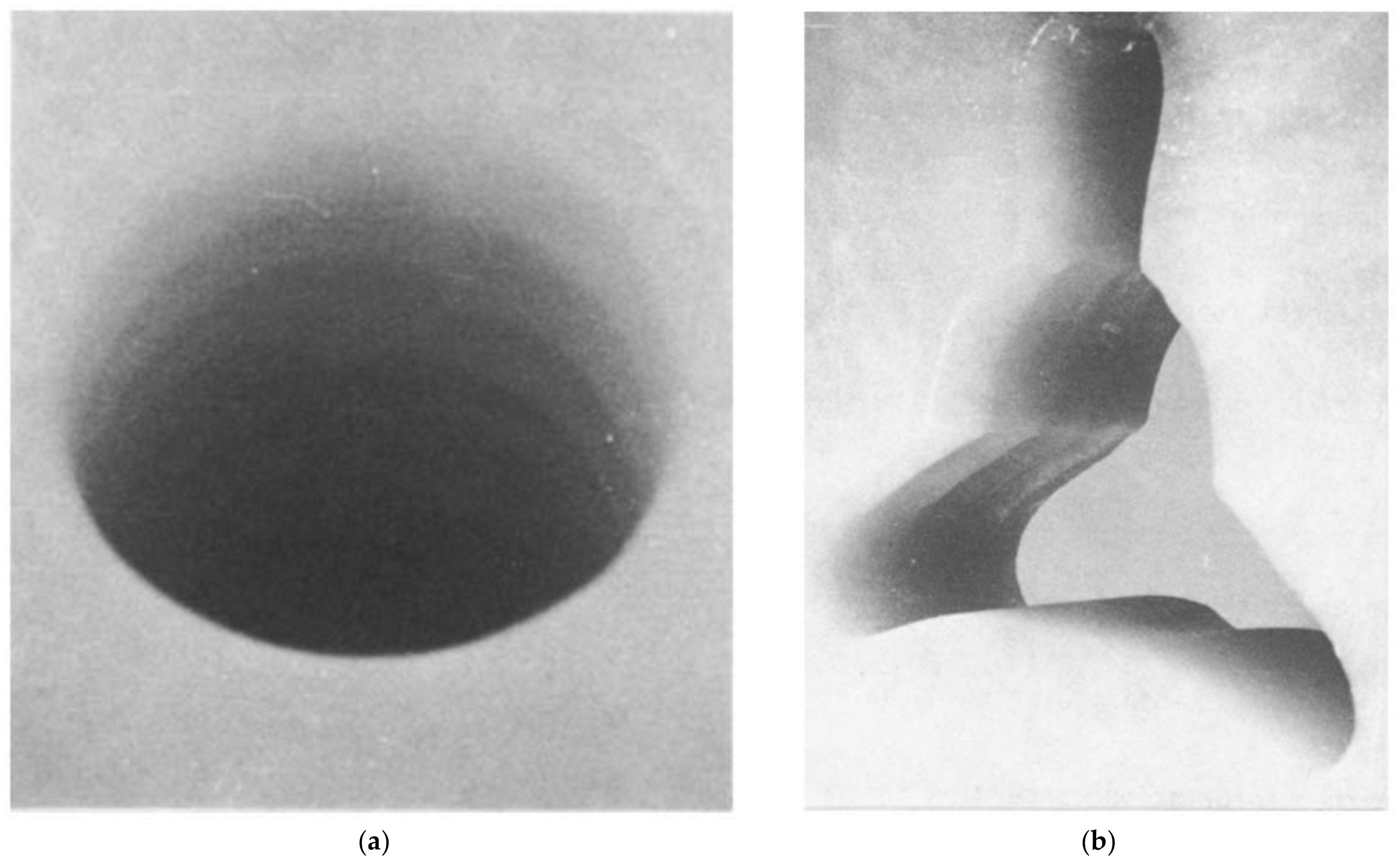
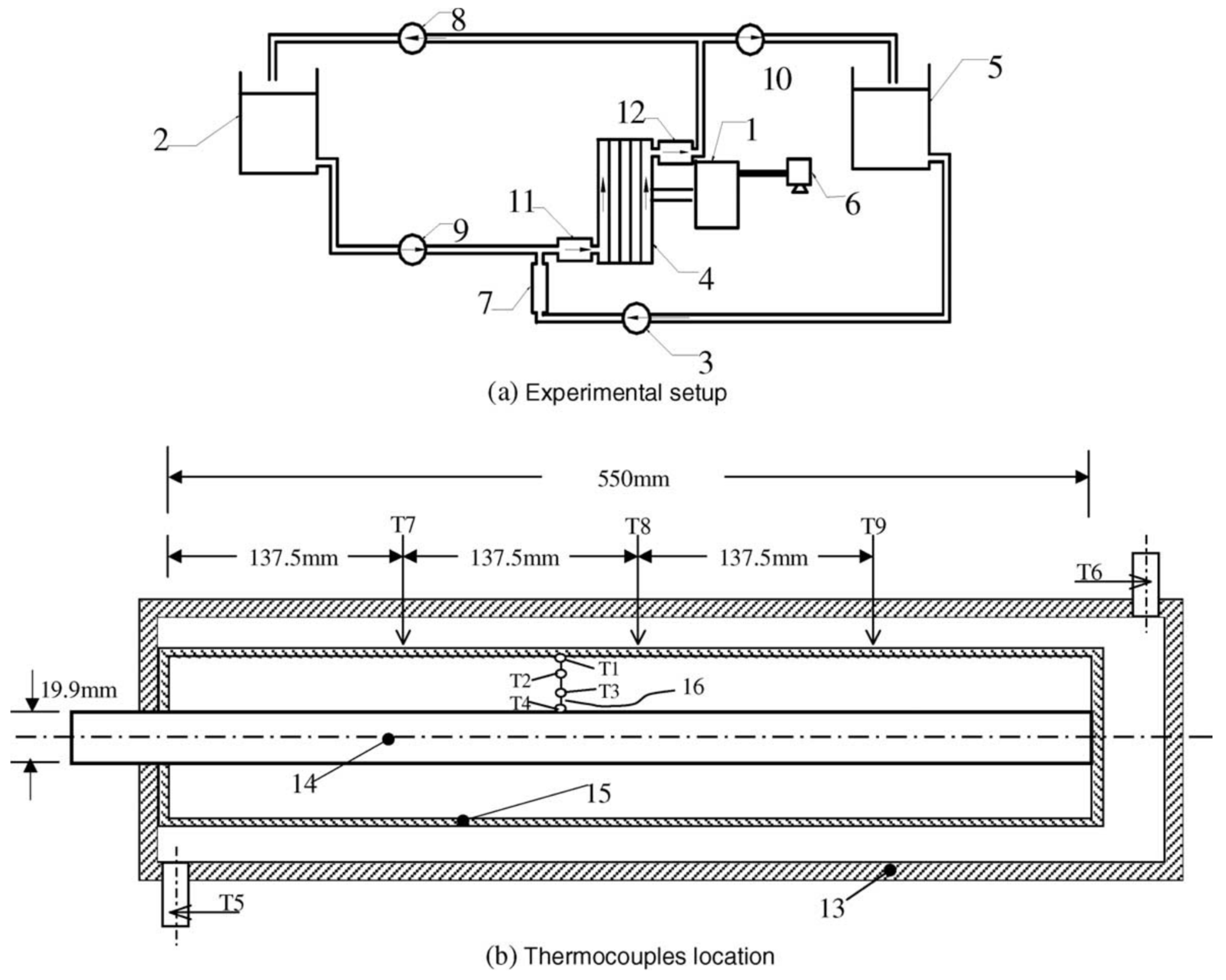
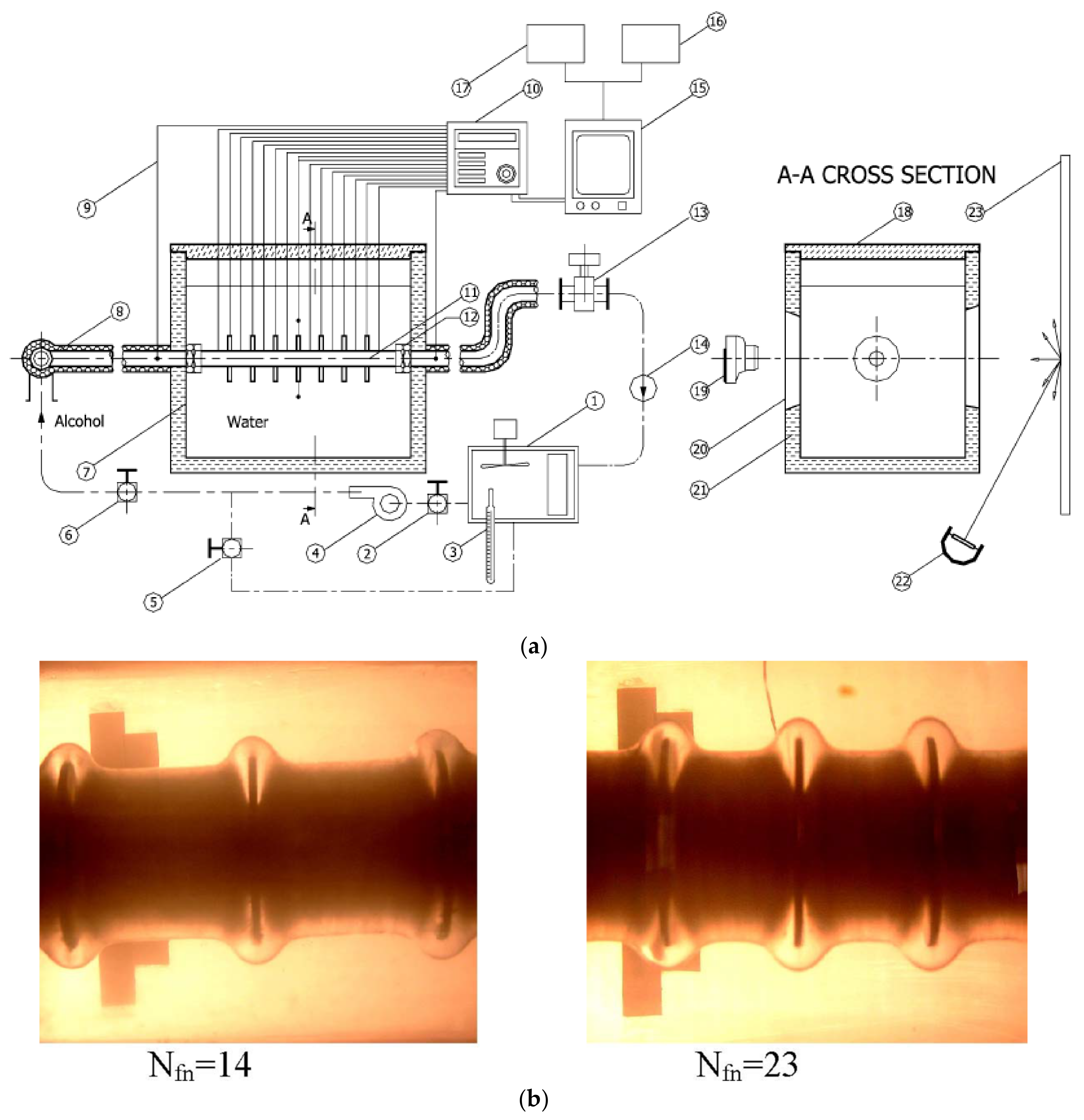
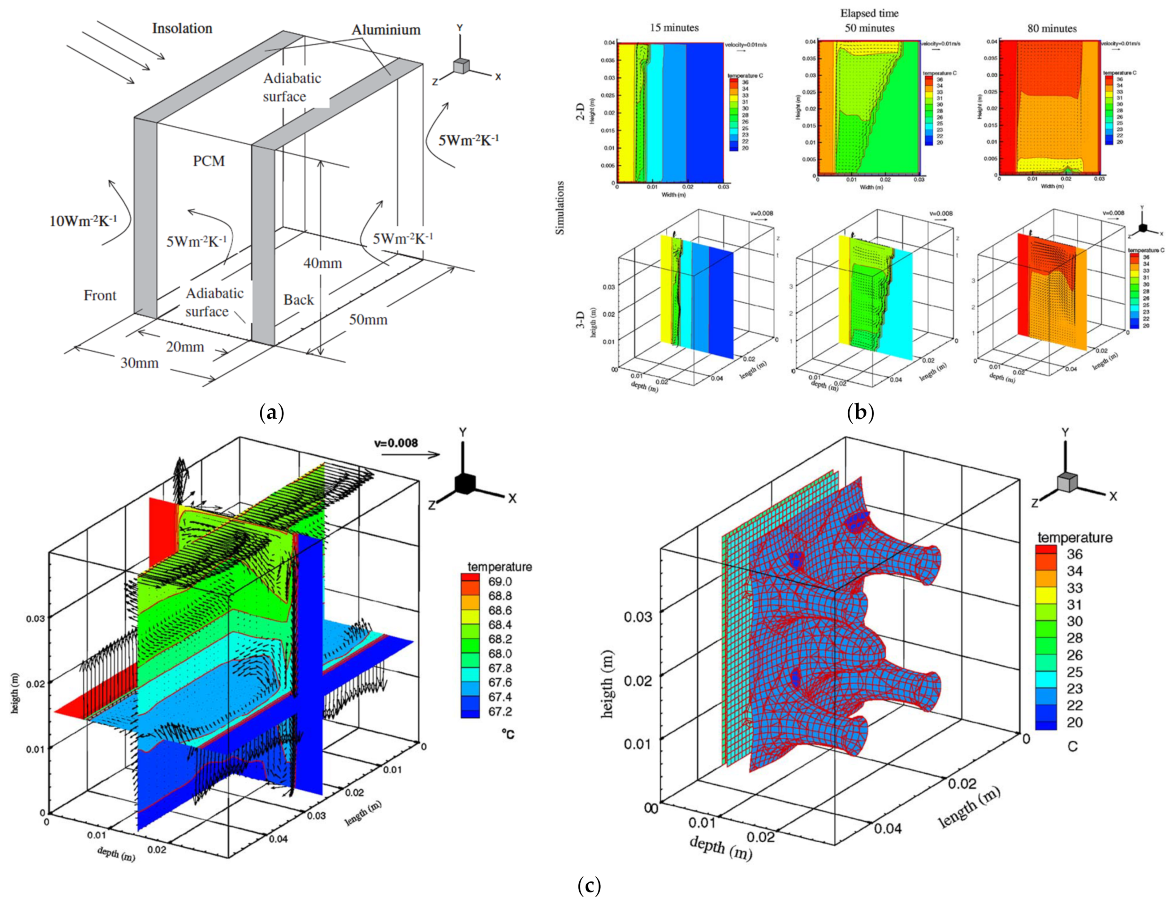
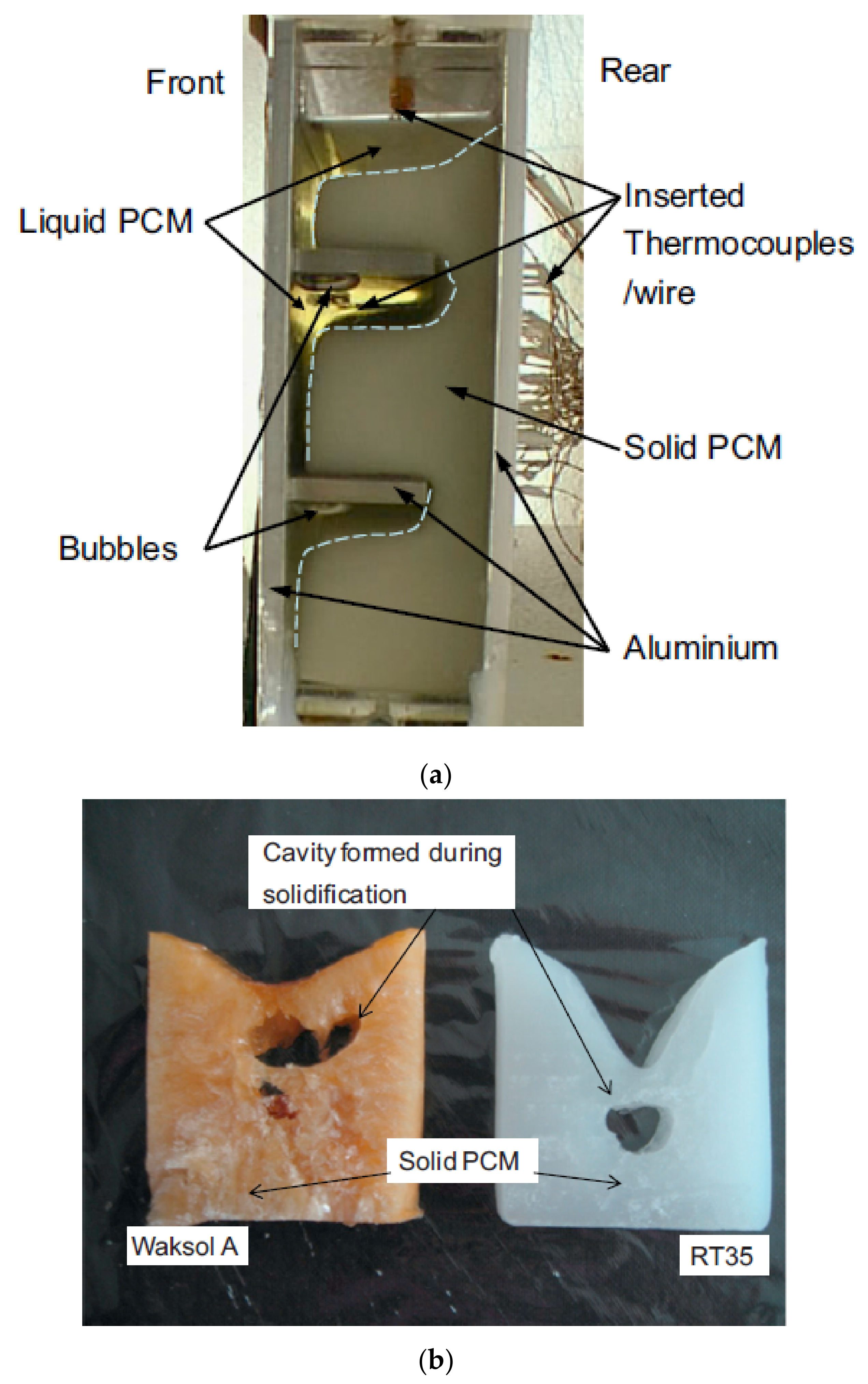
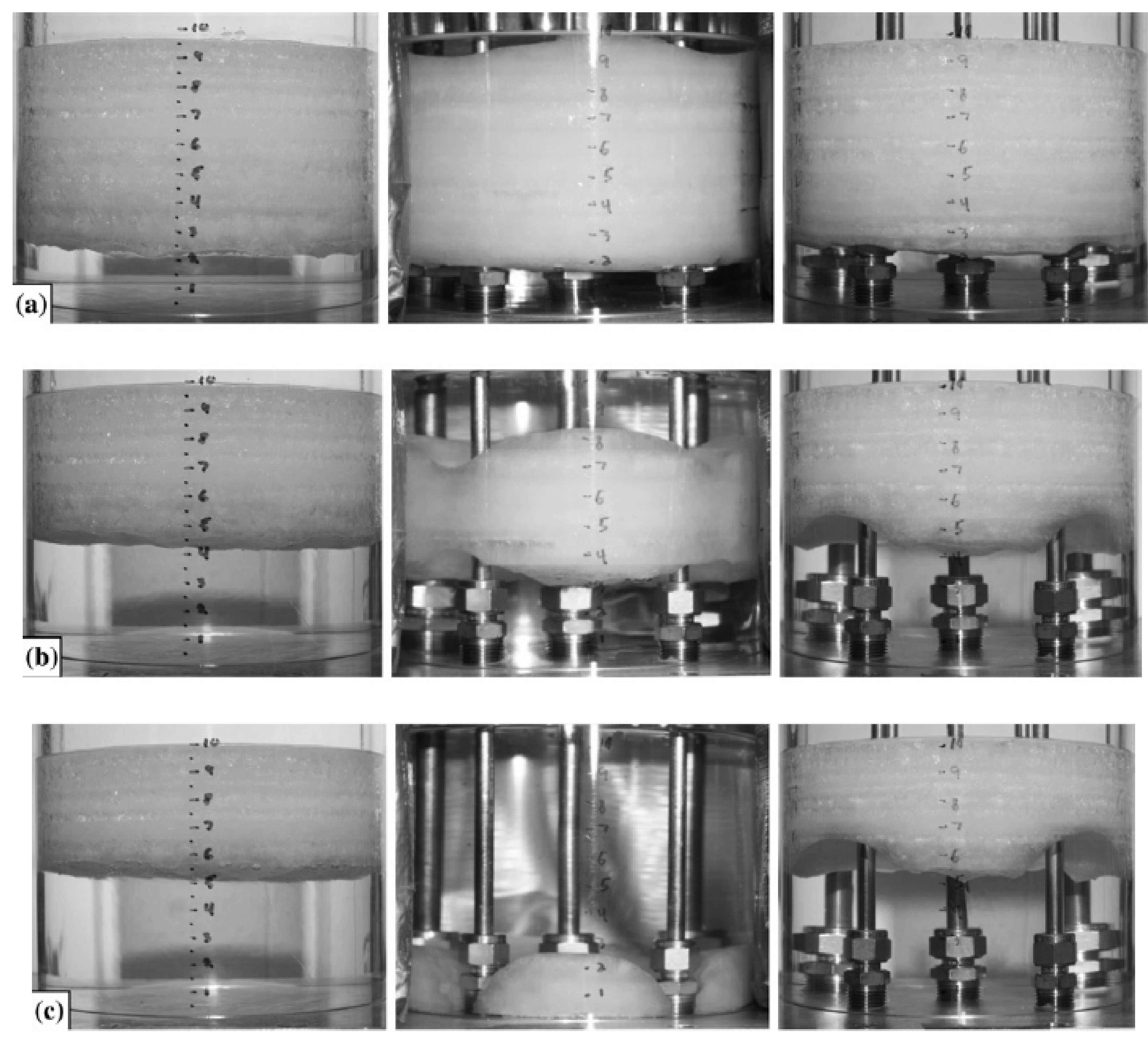
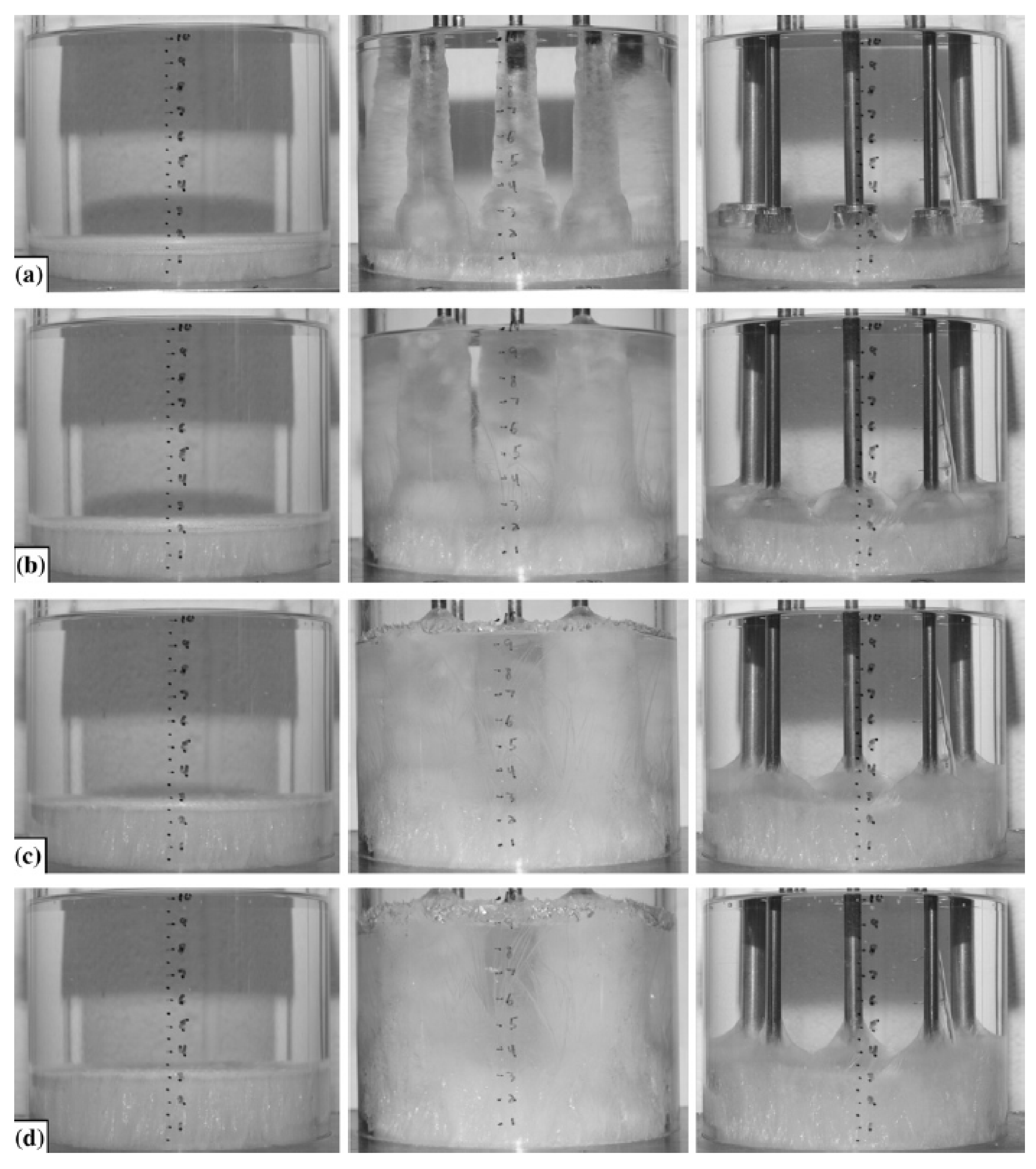
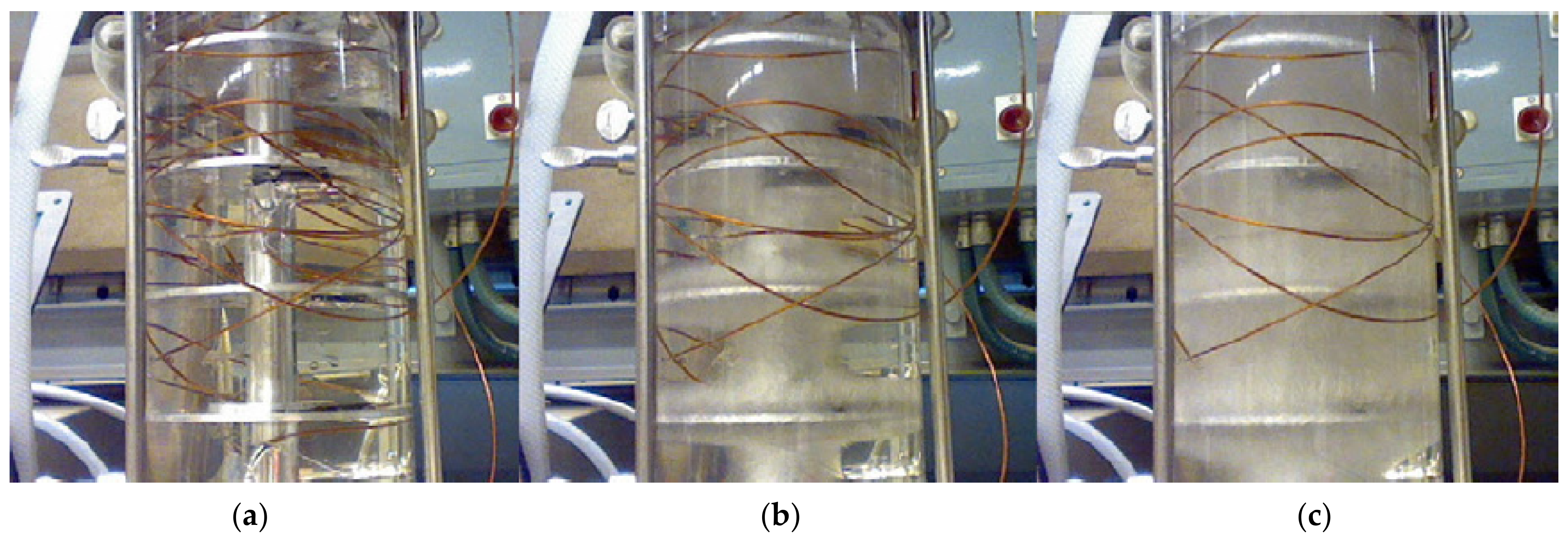
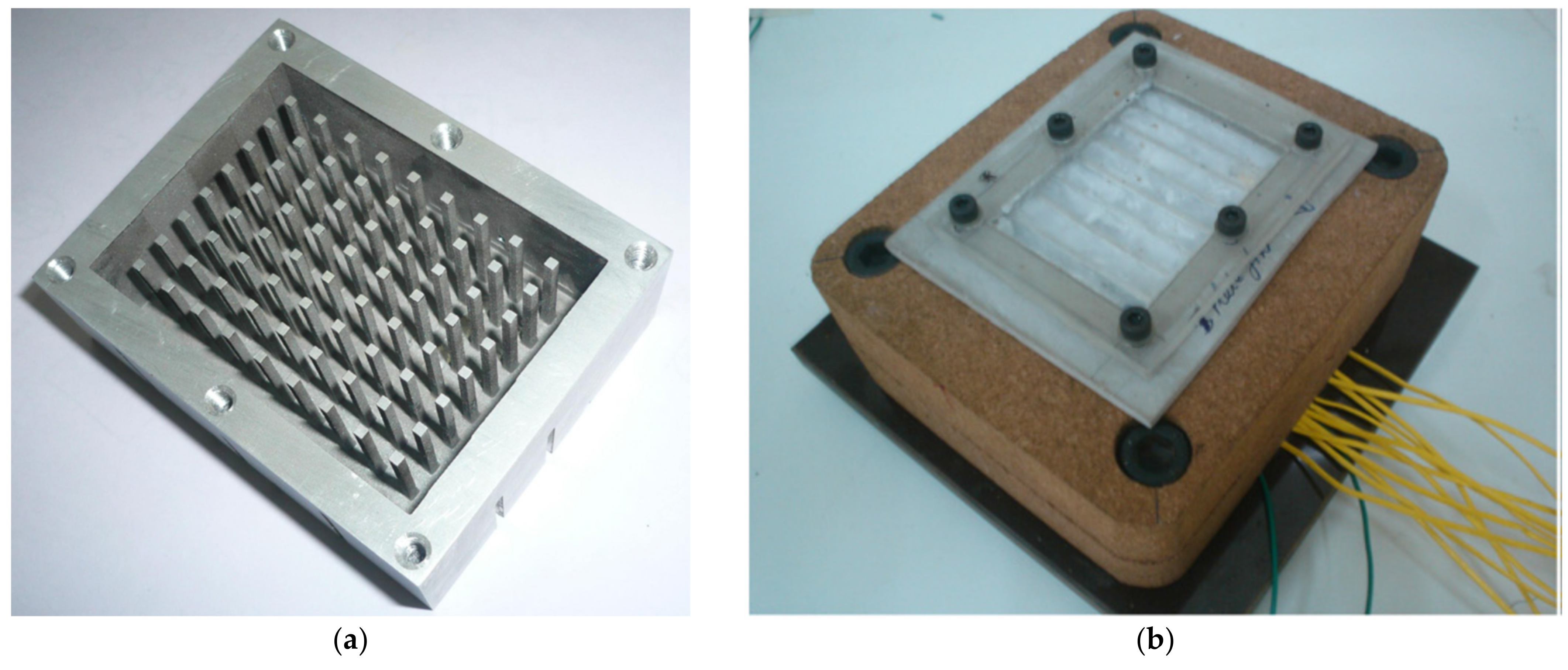
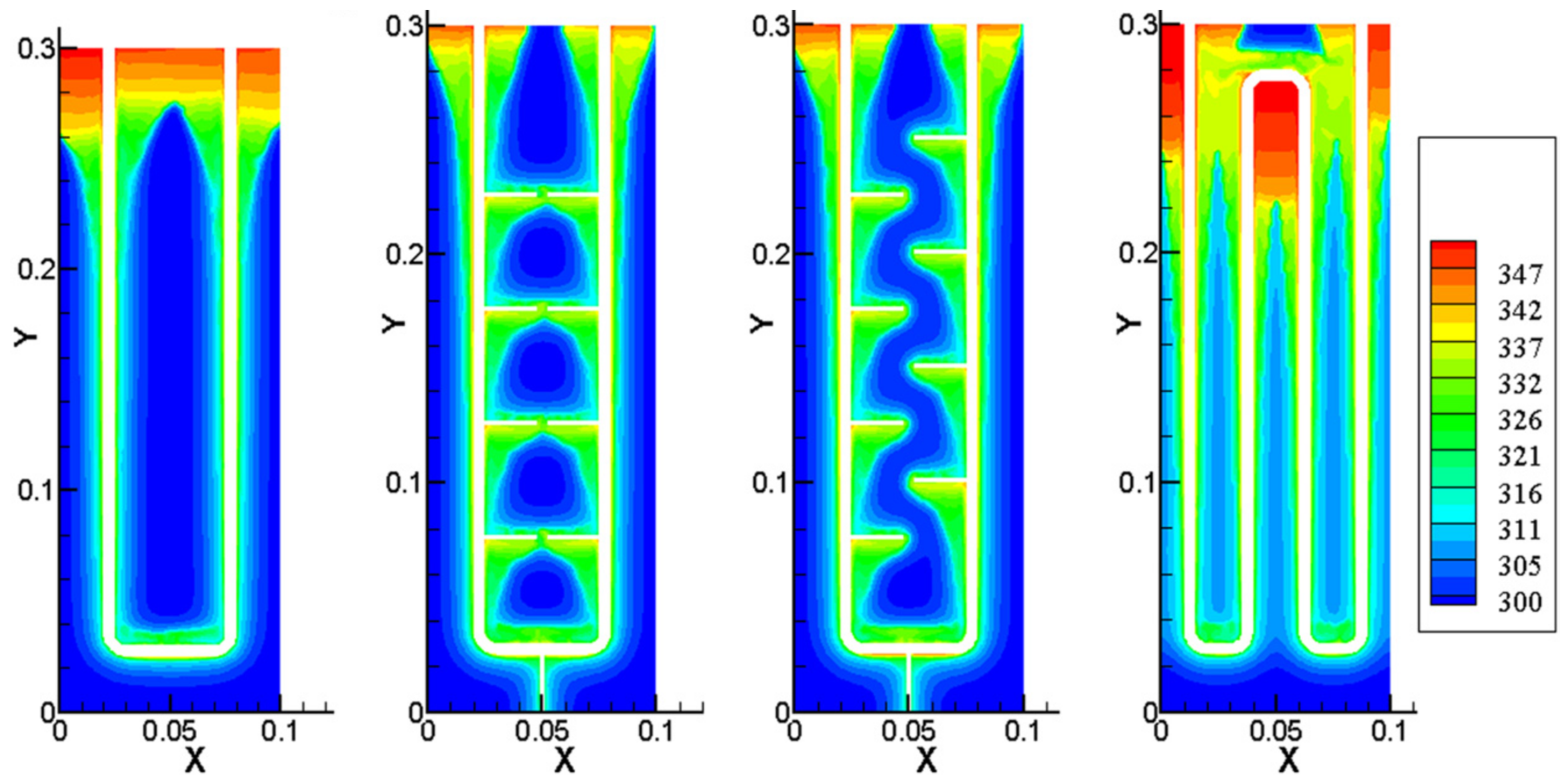
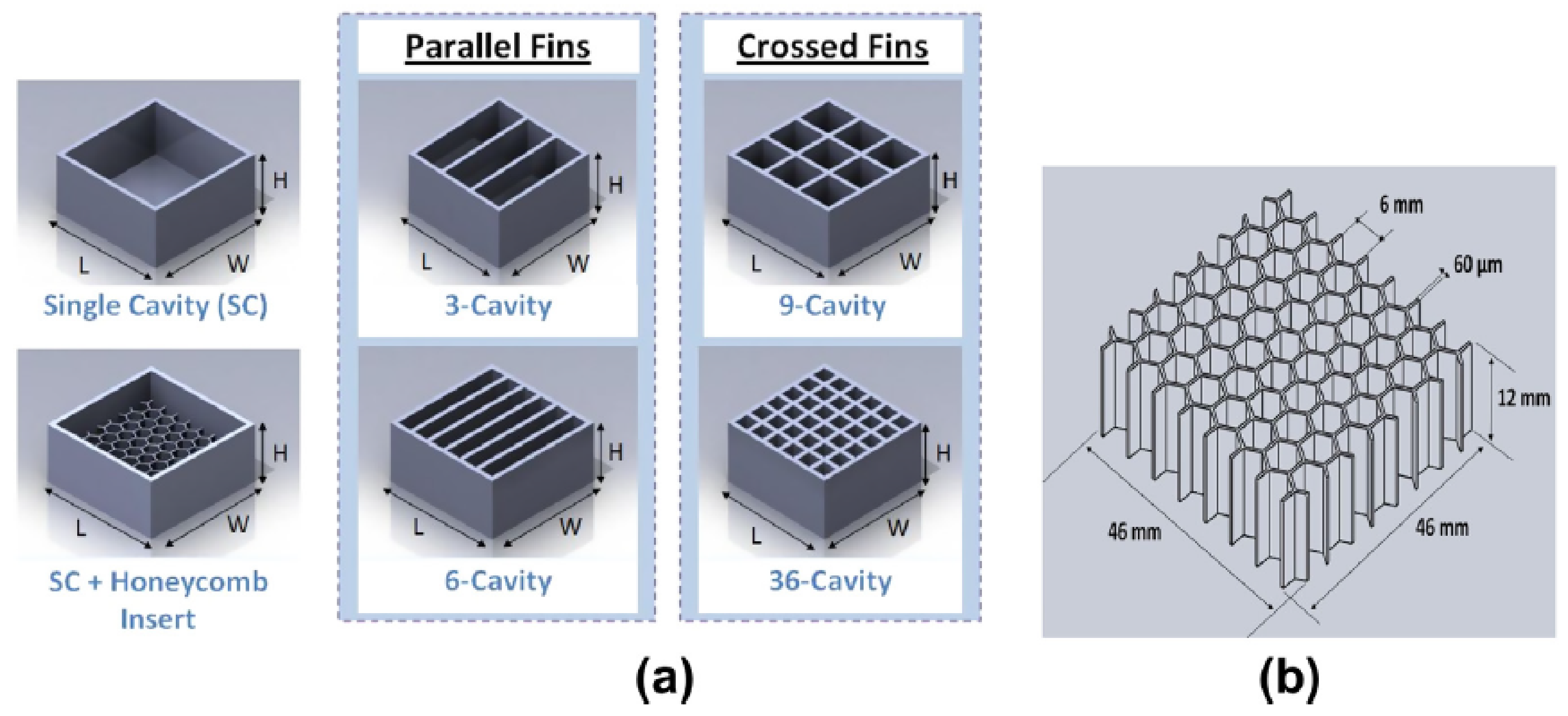
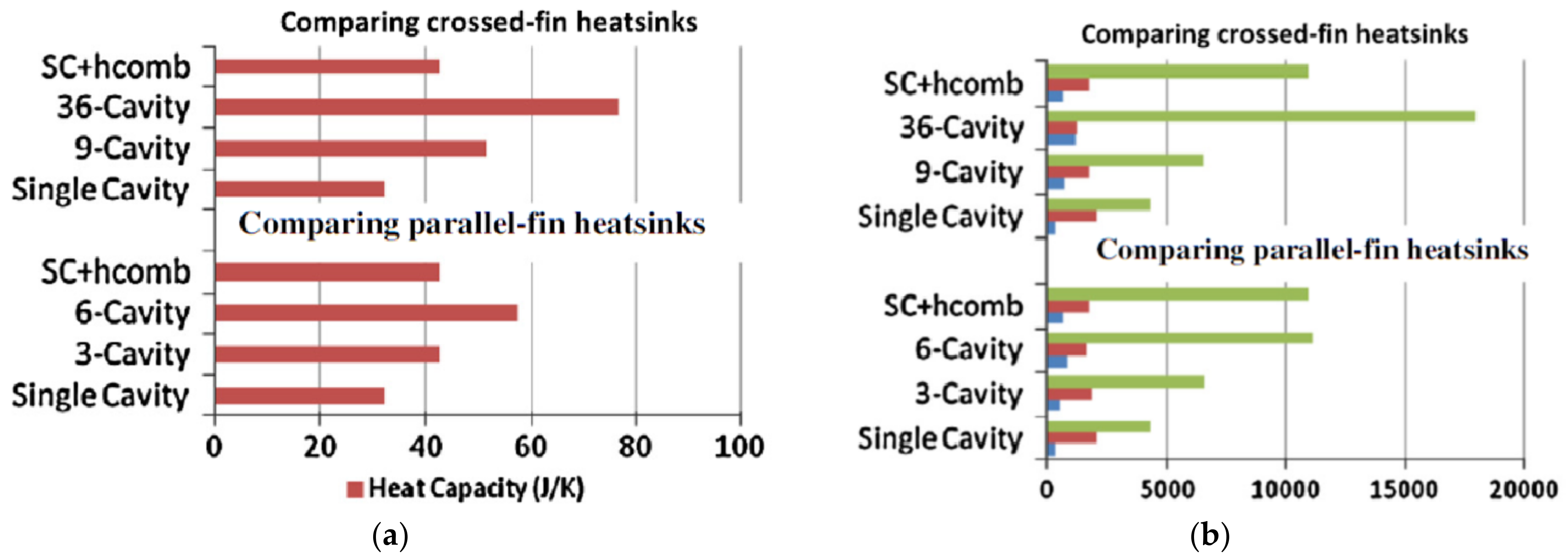
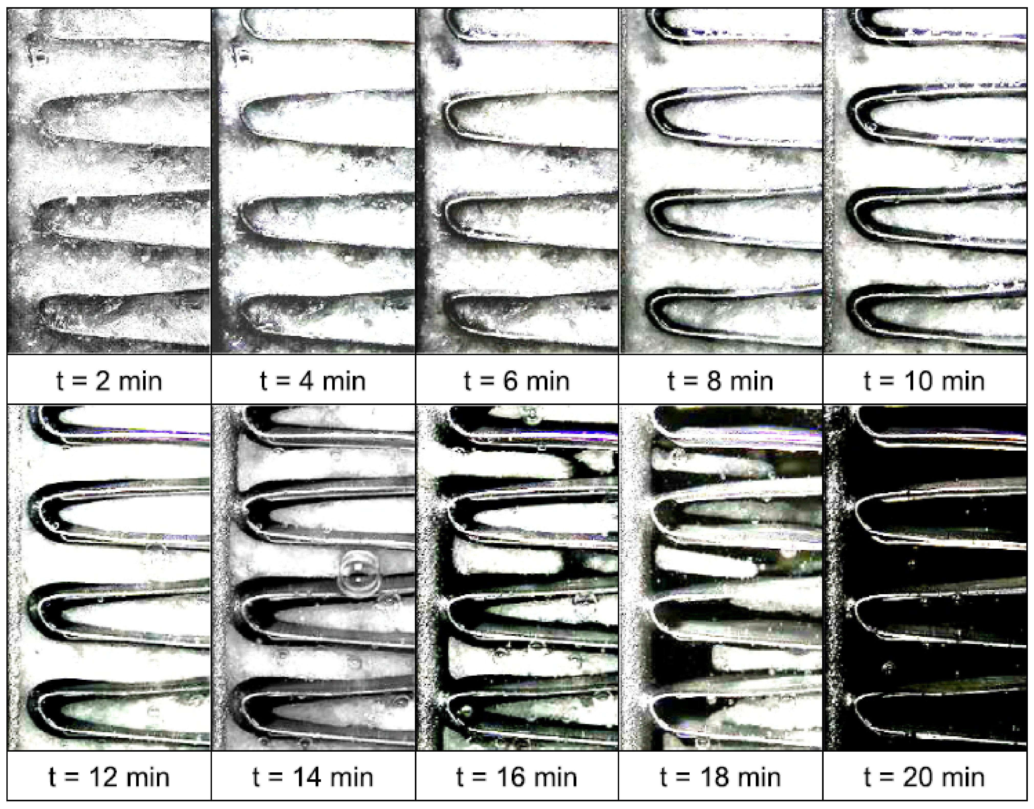
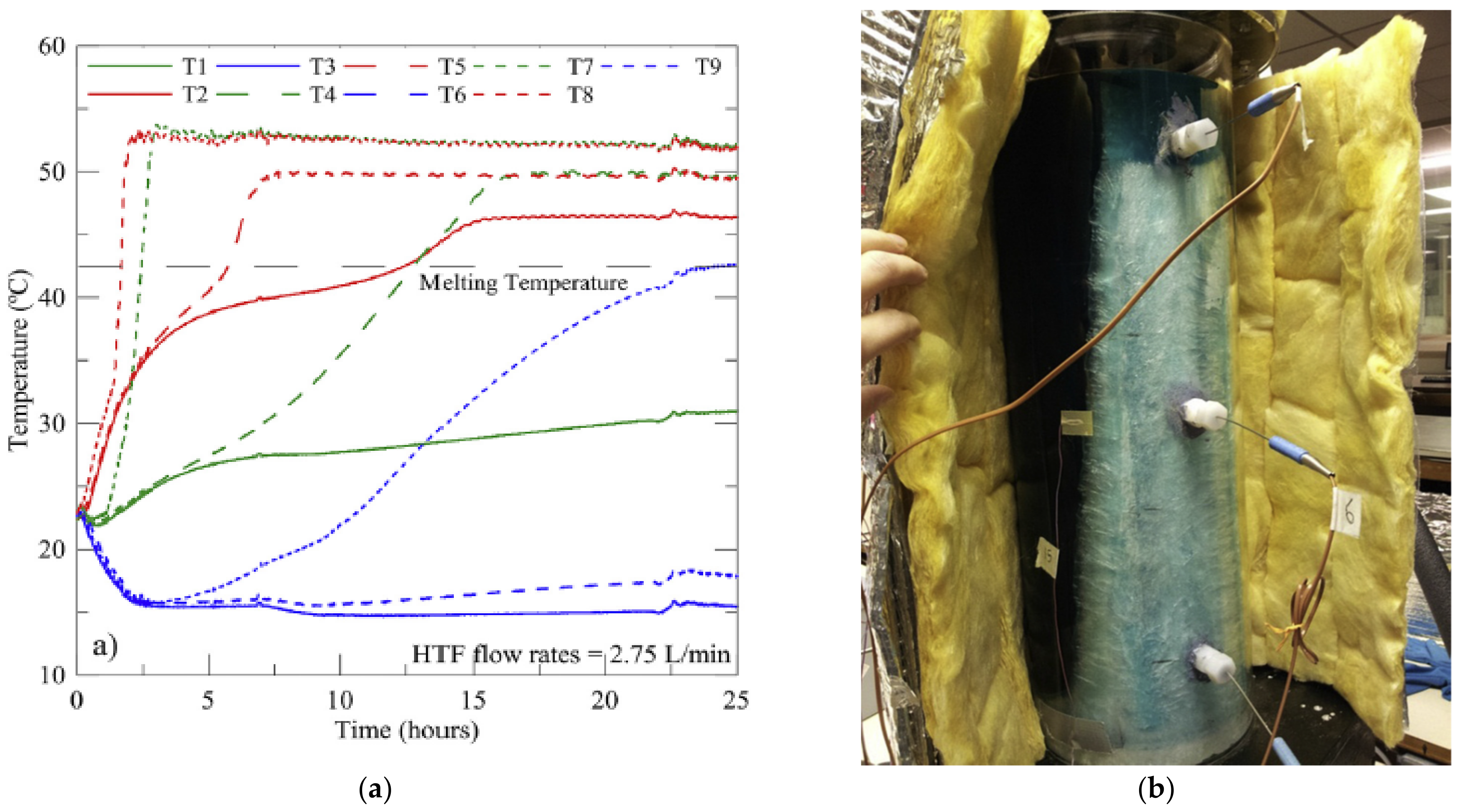
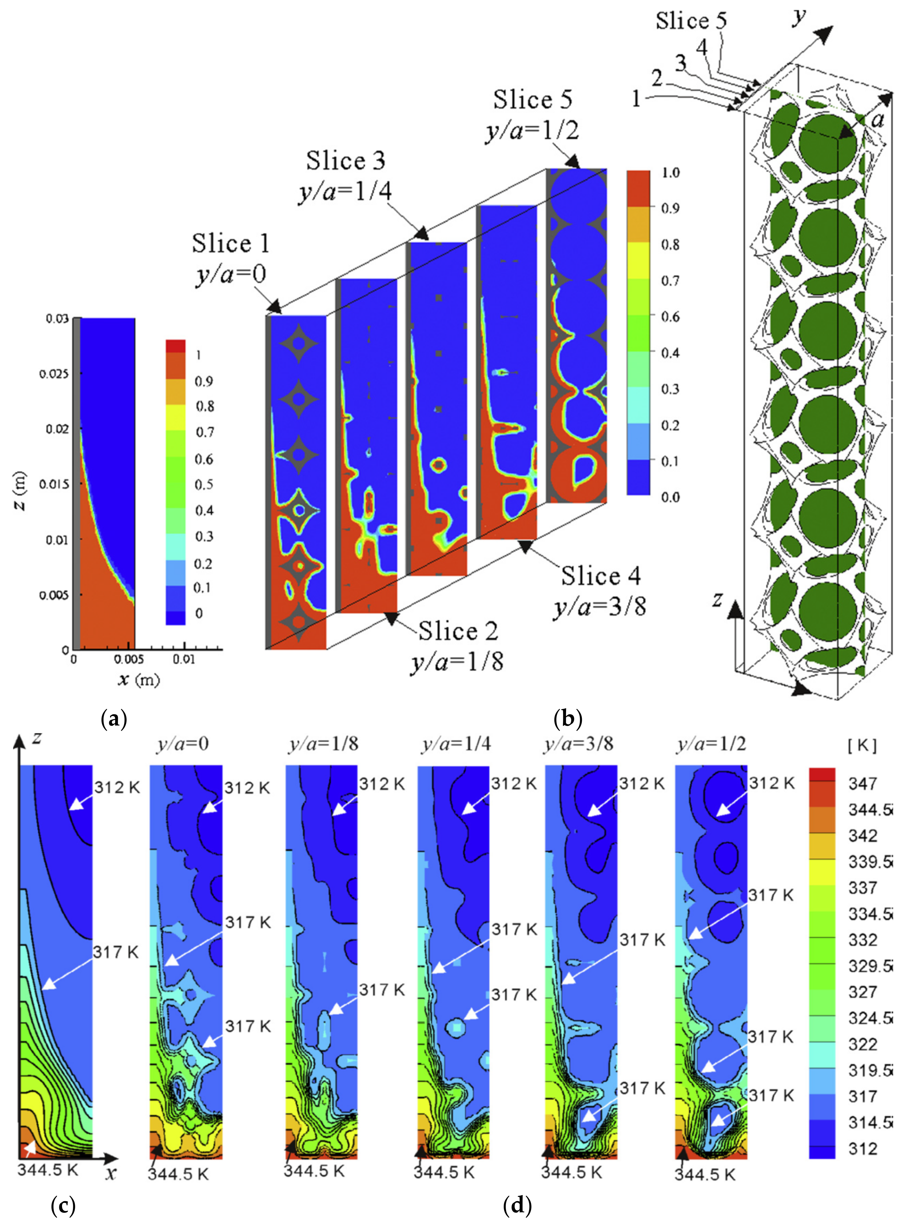
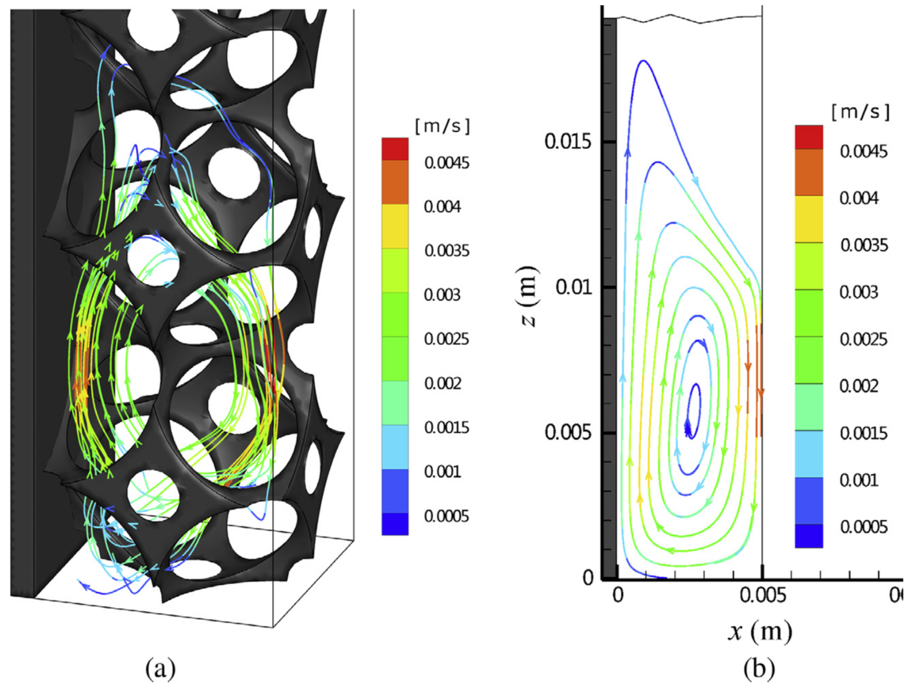
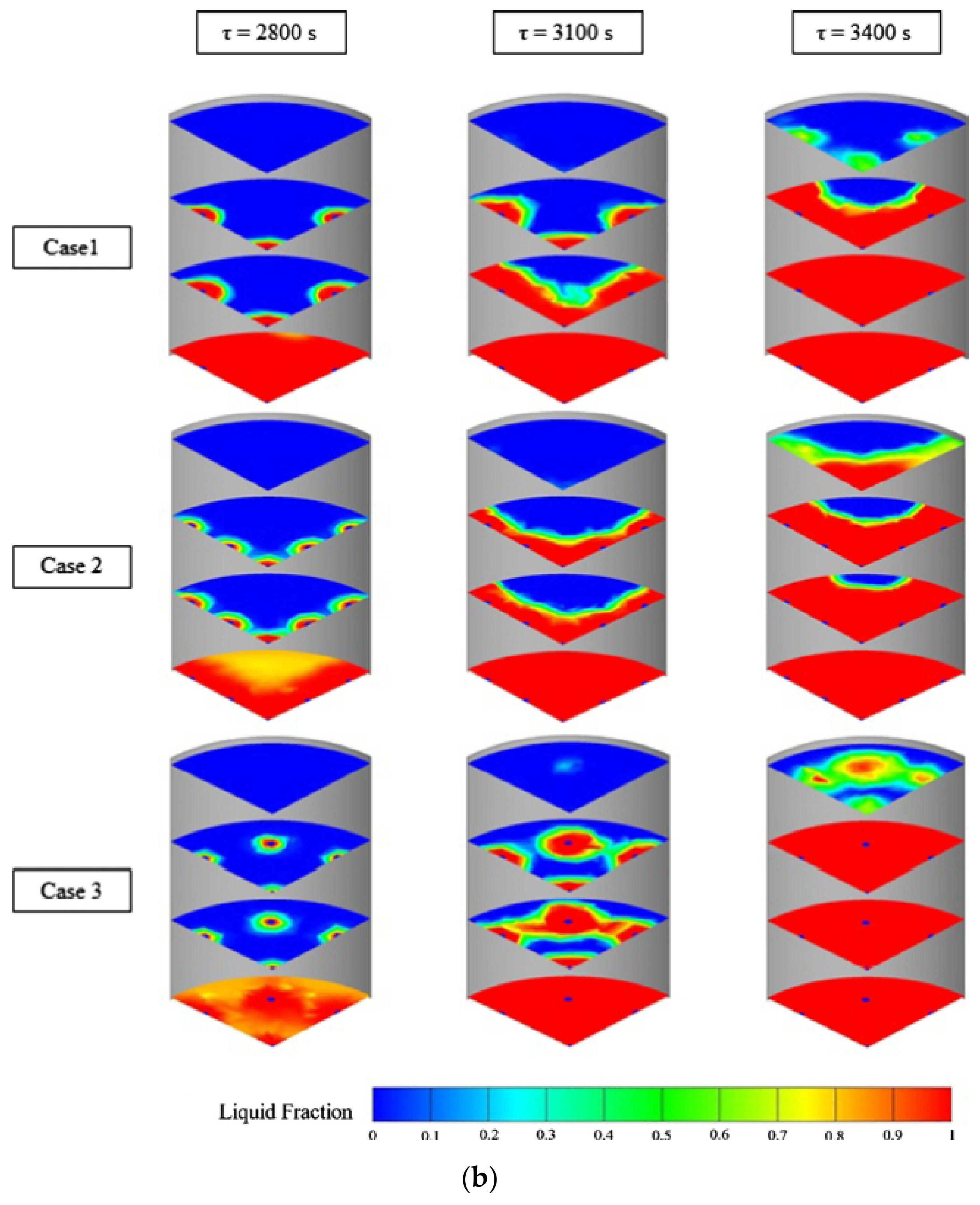
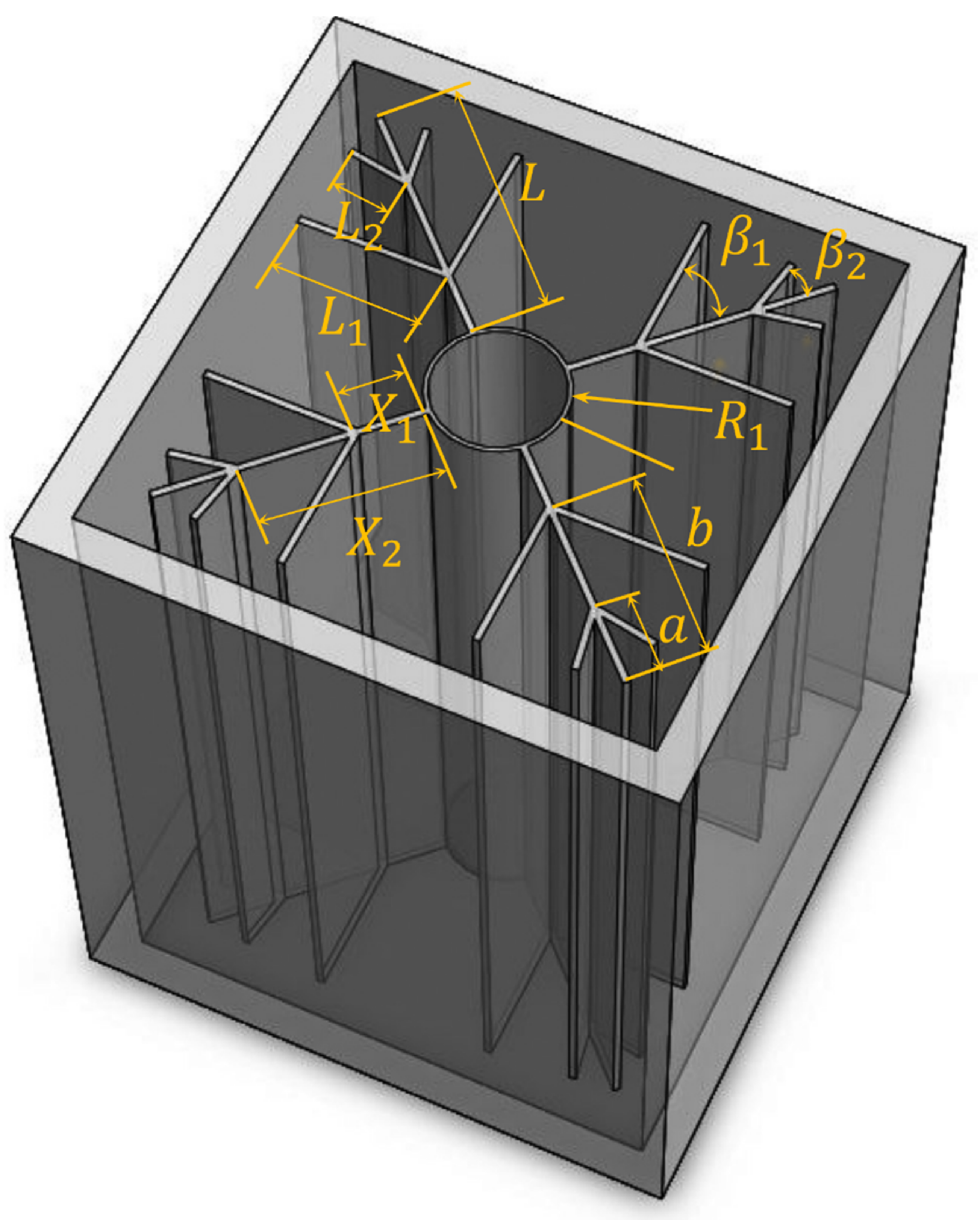
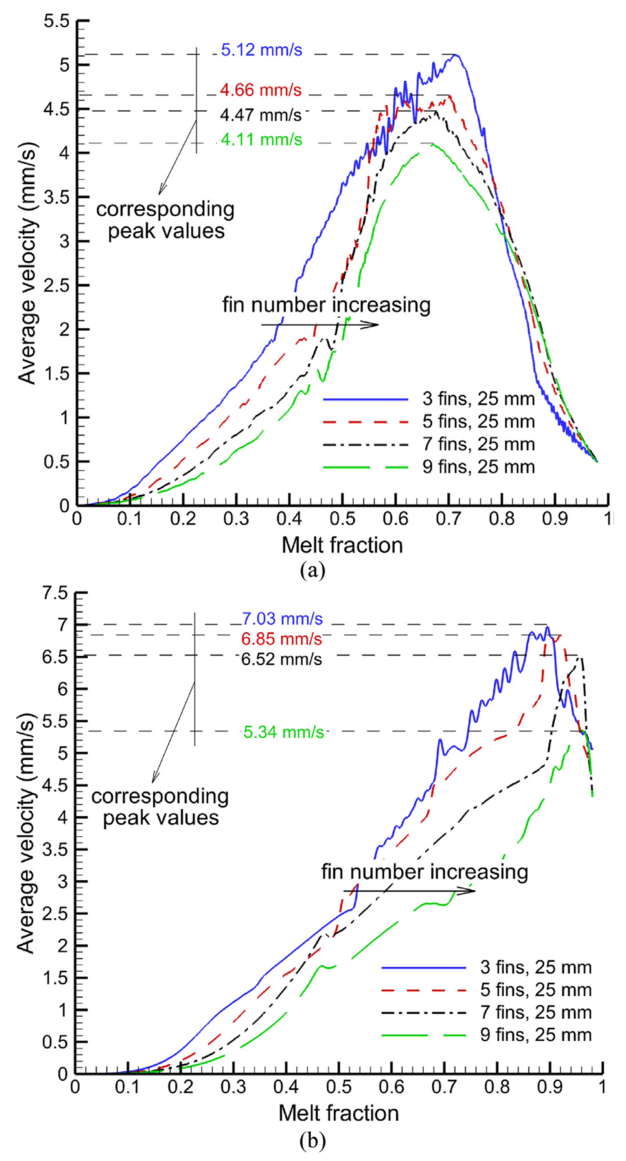
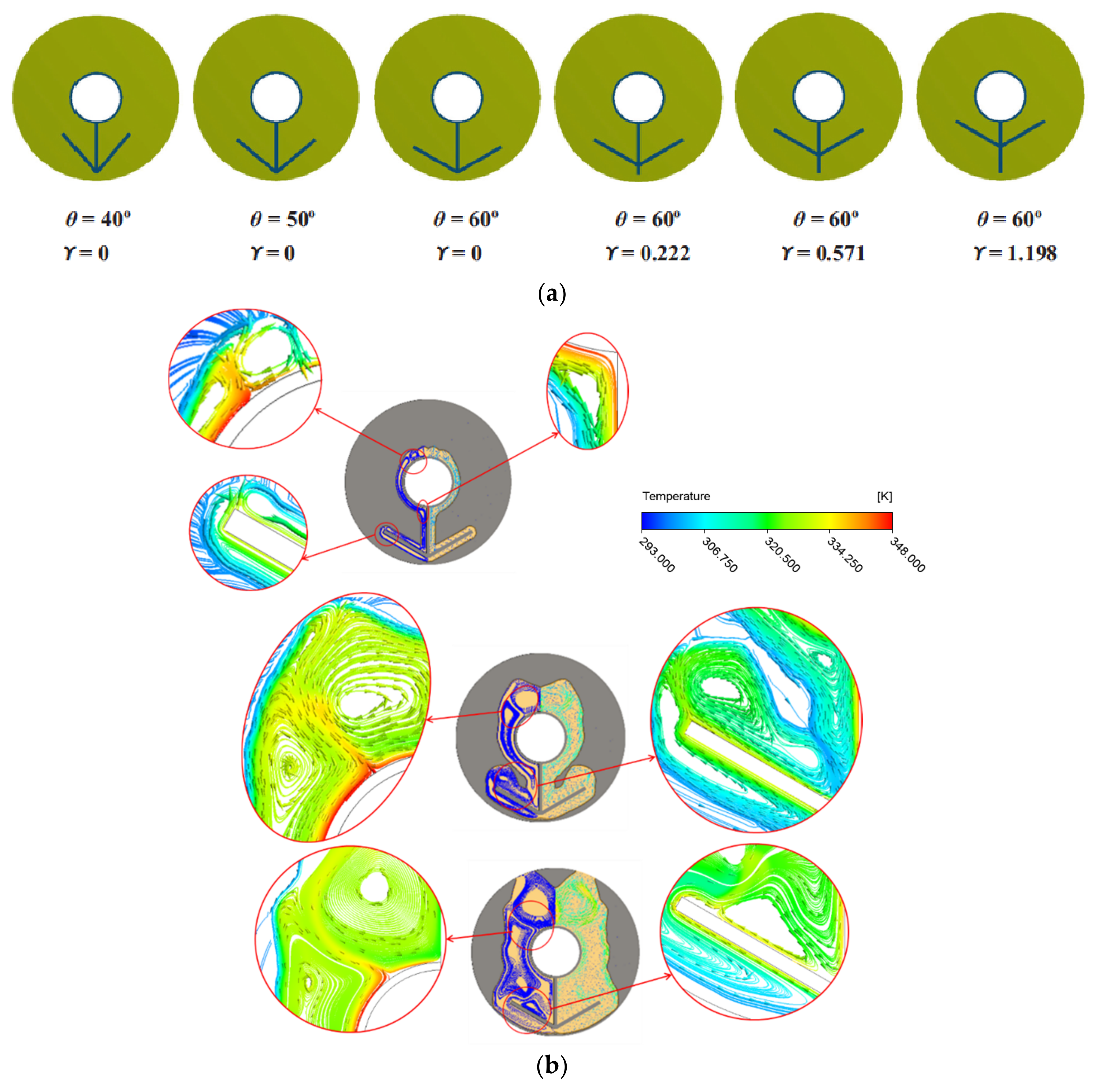