Article

A Global Tracking Sensorless Adaptive PI-PBC Design for Output Voltage Regulation in a Boost Converter Feeding a DC Microgrid

by
Walter Gil-González
1,
Oscar Danilo Montoya
2,3,
Sebastián Riffo
4,*,
Carlos Restrepo
4,5 and
Javier Muñoz
4
1
Department of Electrical Engineering, Universidad Tecnológica de Pereira, Pereira 660003, Colombia
2
Grupo de Compatibilidad e Interferencia Electromagnética, Facultad de Ingeniería, Universidad Distrital Francisco José de Caldas, Bogotá 110231, Colombia
3
Laboratorio Inteligente de Energía, Facultad de Ingeniería, Universidad Tecnológica de Bolívar, Cartagena 131001, Colombia
4
Department of Electrical Engineering, Universidad de Talca, Curicó 3340000, Chile
5
Principal Investigator Millennium Institute on Green Ammonia as Energy Vector (MIGA), Santiago 7820436, Chile
*
Author to whom correspondence should be addressed.
Energies 2023, 16(3), 1106; https://doi.org/10.3390/en16031106
Submission received: 19 December 2022 / Revised: 10 January 2023 / Accepted: 15 January 2023 / Published: 19 January 2023
(This article belongs to the Special Issue Emerging Topics in Power Electronic Converters of Microgrids)

Abstract

:
The problem of the output voltage regulation in a DC-DC boost converter feeding a DC microgrid is addressed in this research via the passivity-based control theory with a proportional–integral action (PI-PBC). Two external input estimators were implemented in conjunction with the proposed controller to make it sensorless and adaptive. The first estimator corresponds to the immersion & invariance (I&I) approach applied to calculate the expected value of the DC load, which is modeled as an unknown DC current. The second estimator is based on the disturbance–observer (DO) approach, which reaches the value of the voltage input. The main advantage of both estimators is that these ensure exponential convergence under steady-state operating conditions, and their parametrization only requires the definition of an integral gain. A comparative analysis with simulations demonstrates that the proposed PI-PBC approach is effective in regulating/controlling the voltage profile in unknown DC loads as compared to the adaptive sliding mode controller. Experimental validations have demonstrated that the proposed PI-PBC approach, in conjunction with the I&I and the DO estimators, allowed regulation of the voltage output profile in the terminals of the DC load with asymptotic stability properties and fast convergence times (1.87 ms) and acceptably overshoots (6.1%) when the voltage input varies its magnitude (from 10 to 12 V and from 10 to 8 V) considering that the DC load changed with a square waveform between 1 and 2 A with 100 Hz.

1. Introduction

Electrical power networks have been rapidly transformed from the classical vertical structures composed of generation, transmission, distribution, and commercialization stages that are connected in a common vertical structure [1] into complex networks that, at any voltage level, can integrate distributed energy resources and active users [2]. The main trigger for this change corresponds to the advance in power electronic conversion technologies [3,4]. These electronic devices have made possible the usage of DC energy storage technologies (batteries, supercapacitors, and superconductors) in conventional power grids [5,6], such as the integration of different renewable energy resources with different operating frequencies as wind turbines composed of induction or synchronous machines [4,7] or the integration of DC sources as photovoltaic generation systems in distribution grids [8], as well as voltage output regulation in nonlinear loads [9]. In addition, power electronic converters have made possible the hybridization of classical AC networks by introducing DC transmission and distribution lines and also DC distribution networks and microgrids [10,11]. Nevertheless, of the power electronic converter selected and its application, the main challenge when these devices are used corresponds to the design of an efficient and reliable control technique that reaches the desired reference values with zero steady-state errors and fast convergence times [12].
Due to the rapid growth and acceptance of the industry and academy of DC systems and their applications (as seen in Figure 1), our research is interested in a particular application regarding the output voltage regulation in DC microgrids fed by a boost converter. This conversion topology can integrate general loads composed of constant resistances, powers, and load currents that model DC nonlinear consumptions connected to its terminals.
Several investigations into the control of the boost converter have been proposed in the specialized literature. In [13], a sliding mode control (SMC) was designed to regulate the output voltage of a boost converter that fed a constant power load. In this reference, a switching surface for the SMC approach was presented that decreases the inrush current of the boost converter. Additionally, an observer of external disturbances was included to maintain the output voltage of the boost converter at the desired value. In [14], a stability analysis of a boost converter supplying a nonlinear load that behaves as a constant power load (CPL) was explained. This analysis was performed without battery energy storage. The authors of [15] designed an SCM approach using pulse-width modulation (PWM) to relieve the possible instabilities in DC microgrids generated by nonlinear loads, such as CPL. In [16], the author showed an adaptive controller based on a backstepping SCM approach to stabilize the output voltage of a boost converter connected to a nonlinear load. Refs. [17,18] presented an incremental model for the boost converter to implement a passivity-based control (PBC) that controlled the output voltage of a boost converter considering time-varying disturbances. Furthermore, they included a proportional–integral (PI) observer to refuse the disturbance in the system. A type-II fuzzy approach employing PWM was discussed in [19] to regulate the output voltage of a boost converter feeding a CPL. In [20], a nonlinear controller was designed to stabilize the output voltage of a boost converter connected to a nonlinear load. The nonlinear controller comprises an SMC approach and a finite-time parameter observer, making it a robust controller. A nonlinear control for a boost-type DC-DC converter was described in [21]. This controller used a PBC strategy, including the concept of the interconnection and damping assignment (IDA), which forms the controller in the IDA-PBC approach. This controller can design a control law that guarantees the system’s stability in a closed loop and preserve the passive feature of the system. In [22], a nonlinear controller for regulating the output voltage of a DC-DC boost converter was presented. The nonlinear controller was based on an adaptive output feedback control that showed good performance under the proposed scenarios, which included a reduced-order state observer to estimate the converter’s inductor current and load conductance. Lastly, a PI-PBC method to regulate the output voltage of a boost converter was studied in [23]. The PI-PBC approach used a parameter estimation-based observer to estimate the converter inductor current. Although these investigations present good results, some present problems when implementing them, and others present a large number of parameters to refine. Furthermore, other investigations only consider one type of load, which does not allow them to be implemented at any point in a microgrid. Lastly, none estimates the input voltage, which requires one more sensor.
Based on the aforementioned revision of the state of the art, this paper contributes the following aspects:
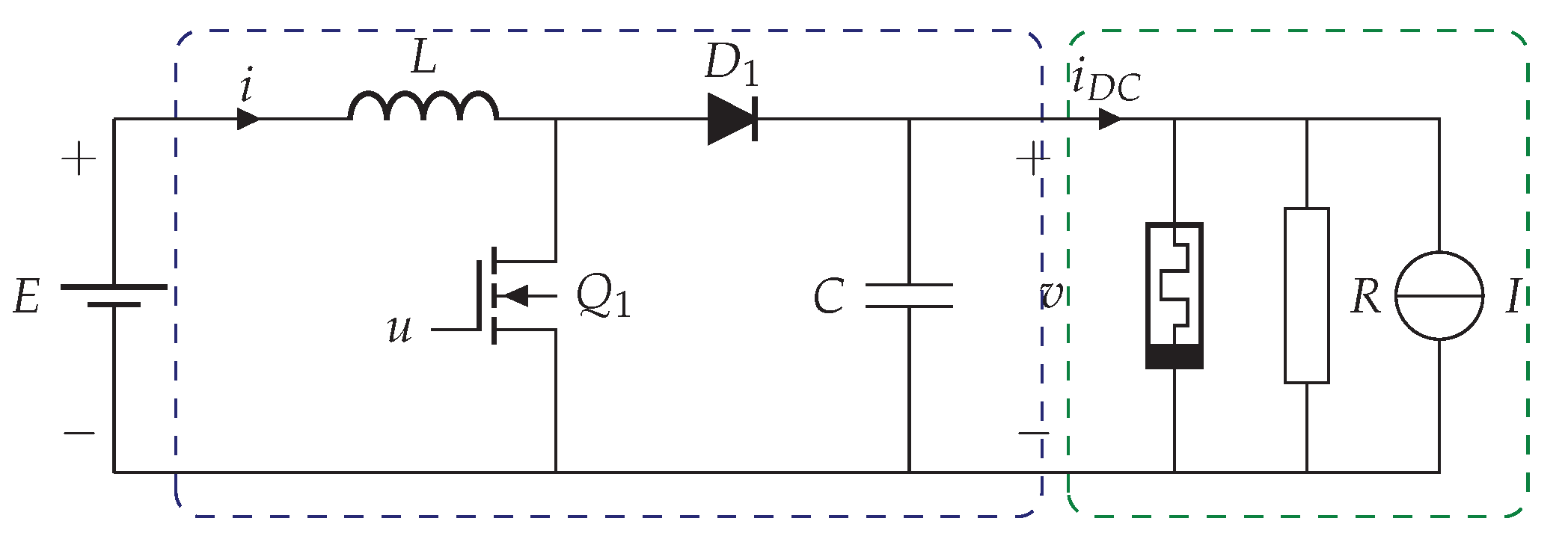
  • The application of the PI-PBC design to regulate the output voltage in a boost converter feeding an unknown DC load that represents the possible consumption in a DC microgrid with constant current, resistance, and power loads, which is modeled as a DC load current.
  • The integration of two external input estimators to the PI-PBC design, both with exponential convergence, allows one to find the expected values for the DC load current (immersion & invariance (I&I) method) and the voltage input (disturbance–observer (DO) approach), which makes our proposed control approach an adaptive- and sensorless-based design.
It is worth mentioning that, in the scope of this contribution, parametric variations in the boost converter parameters, i.e., the inductor and capacitor parameters, are not considered. In addition, the converter is modeled as an ideal conversion device, which implies that the parasitic effects in energy storage devices and semiconductor devices are neglected.
On the other hand, the main advantage of the proposed PI-PBC design is that it is necessary to tune only the two control gains associated with proportional and integral actions since the integral gains associated with the DO and I&I estimators are easy to set (as these are selected to reach the desired speed response). These are set during the experimental validation (online setting).
The remainder of this paper is structured as follows: Section 2 presents the general dynamical modeling of the boost converter feeding a DC microgrid and the general challenges associated with controlling the voltage output in terminals of the DC load. Section 3 shows the general aspects of the PBC theory and the general application of the PI-PBC approach to the boost converter model. Section 4 describes the general aspects of the I&I and DO estimators with their corresponding demonstrations. Section 5 reveals all of the experimental validations of the proposed PI-PBC approach, including the input voltage and the DC load current estimators, and their analysis and discussions are performed. Finally, Section 6 lists the main concluding remarks obtained from this work and some possible work for future research.

2. Mathematical Modeling and Problem Formulation

This section uses the averaging modeling theory to describe the general mathematical modeling of the boost converter feeding a constant power load. It presents the equilibrium point for this system, which is essential in the design of any control approach. In addition, the control problem formulation and the requirements for the voltage regulation of the studied converter are defined.

2.1. Dynamical Modeling and Equilibrium Point

The DC-DC converter is a power electronic converter from the family of second-order converters that boosts the voltage output as compared to the voltage input [24]. It comprises two energy storage devices, i.e., an inductor L and a capacitor C, and two semiconductor devices, one of which is a forced commuted switch based on IGBT technology and a diode. The boost converter’s structure is depicted in Figure 2. Note that i , v , and E R > 0 are the inductor current, output voltage, and input voltage, respectively. P , R , and I R > 0 are the constant power, constant resistance, and constant currents that compose the general DC load, which is modeled as i D C .
To obtain the dynamical model, the averaging modeling theory is applied to the converter. The first Kirchhoff’s law is applied to the node at which the capacitor, inductor, and loads are connected, while the second Kirchhoff’s law is applied to the closed loop that contains the inductor, source, diode, and capacitor. The following set of ordinary differential equations is found:
L i ˙ = 1 u v + E , C v ˙ = 1 u i P v v R I , = 1 u i i D C .
For the sake of simplicity, we define x 1 : = i , x 2 : = v , which yields to the following representation using state variables, where μ = 1 u .
L x 1 ˙ = μ x 2 + E , C x 2 ˙ = μ x 1 i D C .
Remark 1.
Note the assignable equilibrium point for the boost converter model in (2) since it is a DC-DC converter x 1 , x 2 , where x 2 is the expected voltage output in the terminals of the load, which implies that:
μ = E x 2 , x 1 = x 2 E i D C .

2.2. General Control Problem Definition

The main challenges that need to be addressed in supporting the output voltage in a DC load composed of multiple possible consumers are the following:
  • To obtain a general feedback control law that allows for stabilizing of the output voltage x 2 to its desired reference x 2 , thereby ensuring closed-loop stability and fast convergence.
  • To determine the expected value of the load current i D C using an estimator with exponential convergence. The values of the constant resistance, power, and current that compose the loads are unknown, and these are impossible to calculate or estimate since they depend on the DC microgrid connected to the boost converter. The estimator of the load current will make the proposed controller work under a sensorless concept.
  • To apply a disturbance–observer estimator to determine the expected value of the voltage source E with exponential convergence that permits one to obtain a sensorless-based controller approach.
It is worth mentioning that the analysis of the boost converter that supplies the constant voltage profile to a DC microgrid is a complex task due to three main aspects: (i) the usage of estimators to reduce the number of sensors in the physical implementation stage; (ii) the nonlinearities of the boost converter model associated with the products between state variables and the control input; and (iii) the requirement to find a simple control input that ensures asymptotic stability convergence during closed-loop operation.
Note that to ensure efficient output voltage regulation in the terminals of the DC load, a PI-PBC approach is proposed in this research with the main advantage that the final control input does not depend on the converter parameters, as will be demonstrated in the next sections.

3. Passivity-Based Control Theory

Passivity-based control theory is a strong and well-supported nonlinear control theory that deals with a subclass of nonlinear systems that can be represented using a port-Hamiltonian (pH) representation [25]. This representation has the main advantage that it is possible to find a general feedback control law ensuring asymptotic stability in the sense of Lyapunov. At the same time, the passive properties of the pH model of the open-loop model are preserved in closed-loop operation [26]. In the current literature, multiple PBC control designs applicable to pH systems exist; some of these include the standard PBC design [27]; the energy-shaping PBC approach [28]; the interconnection and damping assignation (IDA-PBC) approach [29]; the IDA-PBC approach with integral action; and the PBC with integral action [30]. The selection of each of these methods will depend on the open-loop structure of the dynamical model associated with the physical system under analysis.
In the case of power electronic converters, two main approaches are proposed in the current literature due to the bilinear structure of the converters’ models. The first approach is based on the IDA-PBC theory that allows finding a closed-loop controller by solving a set of partial differential equations regarding the Hamiltonian function and the state variables [26] or also by solving a set of algebraic equations by defining the structure of the Hamiltonian function and the interconnection and damping matrices [31]. In addition, it is possible to add an integral gain to the IDA-PBC approach as a function of the system’s intrinsic passive output to improve the controller’s numerical performance regarding the elimination of possible steady-state errors [30]. The IDA-PBC is the preferred method for power electronic converters when the model contains nonlinear constant power terminals since it deals with these nonlinearities without important complications [9]. The second preferred approach for power converters with a pure bilinear structure, i.e., without the presence of constant power terminals, corresponds to the PI-PBC approach, which exploits the form of the interconnection matrix to relate the state variables with the control inputs to reach a PI-based controller that preserves the passive form of the open-loop model during closed-loop operation with the main advantage that its design ensures global tracking and asymptotic convergence properties [30]. In addition, no partial differential equations are solved, and the PI-PBC approach exploits the well-known benefits of the PI controllers, i.e., robustness, simplicity, and easily adjustable characteristics. In this research, we propose the application of the PI-PBC design for the boost converter to support the voltage profile into an unknown DC load that models the current consumption in a DC microgrid [32].

3.1. PI-PBC Design

The PI-PBC design is a well-known control method for power electronic converters since it exploits the bilinear structure of the converter model to obtain a PI feedback controller [33].
Let us consider a general bilinear system with the structure defined in Equation (4):
D x ˙ = J μ R x + η ,
where D R n × n is defined as the energy storage matrix, which is positive definite and contains in its diagonal all of the parameters related to energy storage devices, i.e., inductors and capacitors in the case of power converters. J ( u ) R n × n is a skew-symmetric matrix known as the interconnection matrix, which is responsible for the bilinear structure of the pH model (4), and R R n × n is a positive semidefinite matrix that contains all of the energy dissipation effects in the pH model, i.e., it is also known as the damping matrix. x R n × 1 is the vector of the state variables, and u R m × 1 ( m < n ) is the vector of the control inputs. η R n × 1 represents the vector of the external inputs. Note that n is the number of state variables, and m is the number of control inputs.
Definition 1.
The pH system (4) has an admissible controllable trajectory x , which fulfills that:
D x ˙ = J μ R x + η ,
for a soft and bounded control input u .
Now, if we define two auxiliary sets of variables, i.e., z = x x , and ω = μ μ , and Equations (4) and (5) are combined, they, the general model known as the dynamics of the error, are found as presented in (6):
D z ˙ = J μ R z + J μ J μ x ,
which can be simplified if the following properties of the skew-symmetric matrix J μ x are applied, i.e., J μ x = J x μ , which transforms (6) into (7).
D z ˙ = J μ R z + J x ω .
Lemma 1.
The dynamical model (7) can be asymptotically stabilized at the operation point ( z = 0 ), with the PI control law defined in (8) and (9):
ω = k p y k i v ,
v ˙ = y ,
where k p and k i are positive constants associated with the proportional and integral gains, y is the passive output of the system, and v is an auxiliary variable. Note that v represents the effect of the integral action associated with the passive output y. However, this variable can be eliminated from Equation (9), changing it to Equation (8). Then, the proposed controller will take the following PI structure:
ω = k p y k i t 0 t y τ d τ .
Proof. 
To ensure the asymptotic stability of the system (7), let us define the following candidate Lyapunov function:
V z , v = 1 2 z D z + 1 2 v k i v ,
which is positive definite for all z , v 0 , and zero only in the equilibrium point, i.e., z , v = 0 . If we take the temporal derivative of (10), it yields the following result:
V ˙ z , v = z D z ˙ + v k i v ˙ ,
where, if the dynamical system (7) and the proposed controller design in (8) and (9) are substituted, then the following result is reached:
V ˙ z , v = z J μ R z + J x k p y k i v + v k i y ,
where is possible to note that:
  • Due to the skew-symmetric properties of the interconnection matrix, i.e., J μ = J μ , then, the component z J μ z is zero;
  • Taking into account that J x = J x for bilinear systems, and defining the passive output as y = z J x , then, (12) can be simplified as follows:
V ˙ z , v = z R z y k p y y k i v + v k i y ,
where it is observed that, if k i is an scalar or diagonal matrix, then y k i v = v k i y , i.e.,
V ˙ z , v = z R z y k p y 0 ,
which ensures that the dynamical system (7) with the PI controller (8) and (9) has an asymptotic stable behavior around the equilibrium point z = 0 , i.e., x = x , which completes the proof. □

3.2. Application to the Boost Converter

The general PI-PBC design presented in the previous subsection can be applied to the boost converter by defining its general bilinear structure as follows:
L 0 0 C x ˙ 1 x ˙ 2 = 0 μ μ 0 x 1 x 2 + E i D C ,
which shows that R = 0 2 × 2 , and J = 0 1 1 0 , which implies that the passive output of the system, i.e., y, can be defined as follows:
y = x J z = x 1 x 2 0 1 1 0 z 1 z 2 = x 1 z 2 x 2 z 1 ,
where, when substituted into Equations (8) and (9), it is possible to find the general PI-PBC controller defined in (17):
ω = k p x 1 x 2 x 2 x 2 x 1 x 1 k i 0 t x 1 x 2 x 2 x 2 x 1 x 1 d τ .
Now, remember that μ = ω + μ . Then, it is necessary to determine the control input in the equilibrium point, i.e., solving (5) with x ˙ = 0 , which allows us to find that:
μ = E x 2 ,
x 1 = x 2 i D C E .
Finally, with the PI controller in (17) and the control input in the operating point (18), the general control law for the boost converter feeding an unknown DC load is u = 1 ω μ , i.e.,
u = 1 E x 2 + k p x 1 x 2 x 2 x 2 x 1 x 1 + k i 0 t x 1 x 2 x 2 x 2 x 1 x 1 d τ .

4. Sensorless Adaptive Design

One of the main challenges in the physical implementation of controllers in engineering science applications corresponds to the availability of the measures regarding state variables and external inputs since these imply an increase in the number of sensors and also introduce non-expected noises into the general control design [23]. For the voltage regulation challenge presented in this research for a boost converter feeding an unknown DC load, we can implement two estimators that can reduce the number of sensors required to implement the control input (20). Each one of these estimators is presented in detail below.

4.1. Estimation of the DC Load Current: Adaptive Control Design

During this stage, to make the proposed controller independent of a sensor that determines the amount of current demanded by the DC microgrid, we present the implementation of the classical immersion & invariance (I&I) estimation approach [34].
Lemma 2.
The I&I estimator allows for the determination of the expected load current ( i D C ) in a boost converter by ensuring exponential convergence. The I&I estimator takes the following form:
i ^ D C = γ ζ x 2 ,
          γ ˙ = ζ C γ ζ x 2 + g 1 x , u ,
where ζ > 0 is a positive constant gain of the I&I estimator, and g 1 x , u is defined as a soft nonlinear function that depends on the state variables and the control input.
Proof. 
Consider that the estimation error is defined by i ˜ D C = i ^ D C i D C , where, if i D C is a constant value, then i ˜ ˙ D C = i ^ ˙ D C . The following equality is obtained after considering the definition of the estimator given in (21).
i ˜ ˙ D C = i ^ ˙ D C = γ ˙ ζ x ˙ 2 .
If it is substituted, and the second equation is associated with the boost converter presented in (2), in conjunction with Equations (21) and (22) combining into (23), then, the next set of equalities yield:
i ˜ ˙ D C = ζ C γ ζ x 2 + g 1 x , u ζ 1 u C x 1 i D C C ,
   = ζ C γ ζ x 2 ζ C g 1 x , u ζ C 1 u x 1 + ζ i D C C ,
= ζ C i ^ D C i D C ζ C g 1 x , u + 1 u x 1 ,
where it is easy to note that the nonlinear function g 1 x , u is defined as u 1 x 1 . In addition, the expected estimation error takes the form presented in (27).
i ˜ ˙ D C = ζ C i ^ D C i D C = ζ C i ˜ D C ,
that allows observing that its solution will tend to zero as defined in (28).
i ˜ D C t = i ˜ D C 0 e ζ C t lim t i ^ D C = i D C ,
which demonstrates that the proposed I&I estimator converges with an exponential form to the expected value of the demanded current. In other words, it permits defining the value of the current load without using a current sensor. □

4.2. Voltage Input Estimation

One contribution to the minimization of the number of measurement elements (sensors) required during the physical implementation of the proposed controller’s approach to regulating the output voltage via the boost converter feeding a DC load is to implement a voltage input estimator via the disturbance–observer (DO) method [35]. As in the case of the I&I method, the DO approach ensures the estimation of the voltage input under steady-state operating conditions with exponential convergence [17].
Lemma 3.
The voltage input that feeds the boost converter can be estimated using the DO method via the estimator with an integral gain defined in (29):
E ^ = α + β x 1 ,
        α ˙ = β L α + β x 1 + g 2 x , u ,
where β is a constant positive definite parameter associated with the integral gain of the DO estimator, and g 2 x , u is defined as a nonlinear soft function that depends on the control input and the state variables.
Proof. 
Let us define the estimation error in the DO approach as E ˜ = E ^ E , where E is the voltage input that is assumed to be a constant value in steady-state conditions, which implies that E ˜ ˙ = E ^ ˙ , which causes the following equality constraint considering the definition of the DO approach in (29):
E ˜ ˙ = E ^ ˙ = α ˙ + β x ˙ 1 .
Note that if we substitute the first equation of the studied dynamic system, defined by (2), in conjunction with the DO equations (29) and (30), into (31), then the following set of equalities is found:
E ˜ ˙ = β L α + β x 1 + g 2 x , u + β E L 1 u L x 2 ,
   = β L α + β x 1 β L g 2 x , u β L 1 u x 2 + β E L ,
= β L E ^ E β L g 2 x , u + 1 u x 2 ,
where it is easy to note that the nonlinear function g 2 x , u is defined as u 1 x 2 . In addition, the expected estimation error takes the form presented in (35).
E ˜ ˙ = β L E ^ E = β L E ˜ ,
which allows for the observation that its solution will tend to zero, as defined in (36),
E ˜ t = E ˜ 0 e β L t lim t E ^ = E ,
which clearly shows that the DO estimation approach effectively allows exponential convergence. In other words, the estimation of the voltage input reached exactly the value of the voltage input feeding the converter, and the proof is complete. □
Figure 3 illustrates the proposed controller plus the estimators.

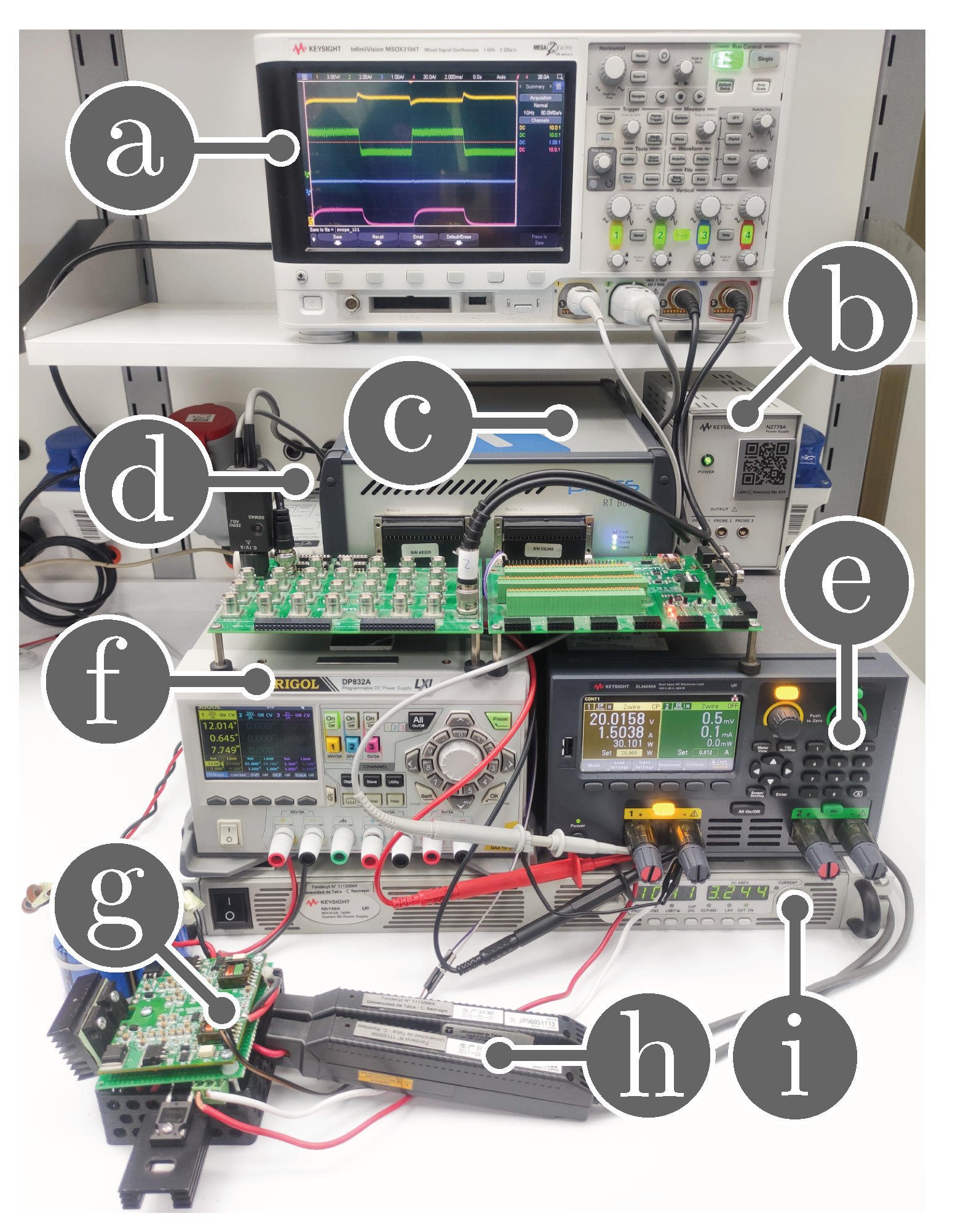
5. Analysis and Experimental Results

This section studies and analyzes the performance of the global tracking sensorless adaptive PI-PBC control to regulate the output voltage regulation in a boost converter feeding a DC microgrid. First, the proposed controller is compared to an SMC approach, which has the following design:
u = 1 i ^ grid ( x 1 + μ ) / C E ^ x 2 / L λ s Q s ( x 1 + μ ) x 1 / C x 2 2 / L , s = x 1 x 2 x 2 x 1 + μ ( x 2 x 2 ) ,
where λ = 5000 , Q = 3 , and μ = 25 are gains of the SMC approach. In addition, it also has estimators to make the comparison fairer.
Second, the experimental results are implemented to assess the proposed controller’s application to the boost converter. The adaptive proposed controller was run in the RT-Bos of Plexim with a time sample of 10 μ S . The boost converter prototype and the devices used in its implementation are depicted in Figure 4, and their values are shown in Table 1. The gains of the adaptive PI-PBC controller were tuned online via the RT-box of Plexim. These gains are: k p = 0.2 , k i = 0.4 , γ = 0.1 , and ζ = 2 .

5.1. Simulation Results

Figure 5 compares a simulation of the boost converter using the proposed controller and the SMC approach. The i grid varies between 1.5 A and 3 A with a 100 Hz square waveform (duty cycle of 0.5 ), and the input voltage E varies instantly, regulating the output voltage to 15 V. Figure 5a shows that the controller’s performance during input voltage is constant. In this figure, it is possible to observe that the proposed controller has less overshoot in the voltage and a faster settling time than the SMC approach. Figure 5b,c illustrates the controller’s performance during the changes in the input voltage from 10 V to 12 V and from 10 V to 8 V, respectively. These figures show that the proposed controller continues to present a better performance than the SMC approach, which has a more straightforward design and ensures closed-loop stability.

5.2. Effect of the Estimate E ^

This part shows the performance of the effect of the estimate E ^ . The aim is to stabilize the output voltage of the boost converter to x 2 = 15 V while the DC current of the microgrid changes between 1.5 A and 3 A with a 100 Hz square waveform. The dynamical response of the proposed controller implemented in the boost converter is presented in Figure 6. Figure 6a shows the response of the proposed controller when the input voltage E is measured. In contrast, Figure 6b illustrates the same scenario when the estimator of the input voltage E ^ is implemented.
Analyzing Figure 6a,b, one can see that the estimation of the input voltage E ^ is correct since the performance of the proposed controller continues to be equal, thereby maintaining the output voltage at the desired value when the DC current of the microgrid changes between 1 A and 2 A with a 100 Hz square waveform. This indicates that the input voltage observer’s design responds appropriately.
Now, in Figure 7, the performance of the estimate E ^ is studied under changes in the input voltage E when the DC current of the microgrid is at a constant value ( i D C = 11 A) by regulating the output voltage at x 2 = 15 V. Figure 7a shows the response of the estimate E ^ when the input voltage varies from 10 V to 12 V while Figure 7a shows the response of the estimate E ^ when the input voltage decreases from 10 V to 8 V.
Figure 7a,b properly show the estimation of the input voltage E ^ ’s response since the estimate E ^ (blue line) can reach the input voltage E, measured (yellow line) with a small error during the transition.

5.3. Performance of the Adaptive Proposed Controller

This part analyzes the performance of the global tracking PI-PBC control during the output voltage regulation in a boost converter feeding an unknown DC microgrid when it includes both estimators. This part considers that the input voltage E and the DC current of the microgrid change simultaneously. The control objective continues to stabilize the output voltage to x 2 = 15 V. Figure 8a presents the output voltage x 2 (yellow line), the inductor current x 1 (green line), the control signal u (blue line), and the estimate i ^ D C (purple line) when the DC current of the microgrid changes between 1 A and 2 A with a 100 Hz square waveform, and the input voltage increases from 10 V to 12 V. Figure 8b shows the input voltage E (yellow line) and its estimate E ^ (blue line).
Observe in Figure 8a that the adaptive proposed controller regulates the output voltage of the boost converter under the variations of the DC current of the microgrid and input voltage. The overshoot for the output voltage x 2 is around 6.1 %, and its settling time is 1.87 ms (see yellow line in Figure 8a). For the case of the inductor current x 1 , its overshoot and settling time are around 2.65 % and 0.96 ms, respectively (see green line in Figure 8a). These results confirm that the proposed controller responds adequately under simultaneous variations in the DC current and the input voltage. Furthermore, Figure 8a shows that the inductor current x 1 (green line) decreases when the input voltage E changes from 10 V to 12 V.
Figure 9a displays the output voltage x 2 (yellow line), the inductor current x 1 (green line), the control signal u (blue line), and the estimate i ^ D C (purple line) when the DC current of the microgrid changes between 1 A and 2 A with a 100 Hz square waveform, and the input voltage increases from 10 V to 8 V. Figure 9b depicts the input voltage E (yellow line) and its estimate E ^ (blue line).
Note in Figure 9a that the adaptive PI-PBC can still stabilize the output voltage of the boost converter at its desired value when the input voltage E and the DC current of the microgrid change simultaneously. This is validated by analyzing the overshoot for the output voltage x 2 and its settling time, which are around 6.1 % ms and 1.87 ms, respectively.
All experimental results validate that the adaptive proposed control adequately regulates the output voltage for a boost converter supplying an unknown DC current in a microgrid. Additionally, the proposed control does not require a voltage sensor, and a current sensor makes it more robust. This is due to the two estimators used in this study, which showed an exponential convergence to the exact value when their behaviors remained constant.

6. Conclusions

The problem of the output voltage regulation in a boost converter feeding an unknown DC load that models a DC microgrid connected at its terminals was addressed in this research through the application of the PI-PBC theory. Two estimators were added to the proposed controller making it an adaptive- and sensorless-based design. The first estimator was the I&I method, which allows for the determination of the expected value of the demanded current using an integral-based estimator. The second estimator corresponded to the DO method, which allowed for the determination of the expected value of the voltage input. The main advantage of both estimators was the exponential convergence properties of these to the desired values.
Experimental validations in the laboratory prototype demonstrated that: (i) the I&I and the DO estimators effectively reached the expected current and voltage values with exponential convergence, and also they responded adequately to faster load variations reaching the mean values of both variables; (ii) the voltage output in terminals of the DC load presented an overshoot of about 6.1 % with a settling time of 1.87 ms when the demanded current experienced variations between 1 A and 2 A with a frequency of 100 Hz in a square waveform, and the voltage input changes from 10 to 12 V, simultaneously; and (iii) the voltage output in terminals of the DC load had the same values for the settling time as the previous case in which the voltage input changed from 10 to 8 V, with the same load current variations, which confirmed the effectiveness of the proposed PI-PBC controller at maintaining a stable voltage output in the boost converter in DC microgrid applications.
In future works, it will be possible to research the following: (i) to extend the proposed PI-PBC approach to other DC-DC second-order topologies (buck, buck-boost, and non-inverting buck-boost) feeding nonlinear loads; (ii) to formulate a passivity-based estimator to eliminate the sensor current used in the inductor of the converter; and (iii) to explore the application of the PBC theory in bidirectional power converters with estimators for external inputs and state variables.

Author Contributions

Conceptualization, methodology, software, and writing (review and editing): W.G.-G., O.D.M., S.R., C.R. and J.M. All authors have read and agreed to the published version of the manuscript.

Funding

This work was partially supported by the Chilean Government under projects ANID/FONDECYT/1191028, ANID/FONDECYT/1191680, and SERC Chile (Anid/Fondap/15110019), as well as the Millenium Institute on Green Ammonia as Energy Vector MIGA (ANID/Millennium Science Initiative Program/ICN2021 023).

Data Availability Statement

No new data were created or analyzed in this study. Data sharing does not apply to this article.

Conflicts of Interest

The authors declare no conflict of interest.

References

  1. Lakshmi, S.; Ganguly, S. Transition of Power Distribution System Planning from Passive to Active Networks: A State-of-the-Art Review and a New Proposal. In Sustainable Energy Technology and Policies; Springer: Singapore, 2017; pp. 87–117. [Google Scholar] [CrossRef]
  2. Tang, Z.; Liu, T.; Zhang, C.; Zheng, Y.; Hill, D.J. Distributed Control of Active Distribution Networks for Frequency Support. In Proceedings of the 2018 Power Systems Computation Conference (PSCC), Dublin, Ireland, 11–15 June 2018. [Google Scholar] [CrossRef]
  3. Afonso, J.L.; Tanta, M.; Pinto, J.G.O.; Monteiro, L.F.C.; Machado, L.; Sousa, T.J.C.; Monteiro, V. A Review on Power Electronics Technologies for Power Quality Improvement. Energies 2021, 14, 8585. [Google Scholar] [CrossRef]
  4. Sekar, R.; Suresh, D.S.; Naganagouda, H. A review on power electronic converters suitable for renewable energy sources. In Proceedings of the 2017 International Conference on Electrical, Electronics, Communication, Computer, and Optimization Techniques (ICEECCOT), Mysuru, India, 15–16 December 2017. [Google Scholar] [CrossRef]
  5. Şahin, M.E.; Blaabjerg, F. A Hybrid PV-Battery/Supercapacitor System and a Basic Active Power Control Proposal in MATLAB/Simulink. Electronics 2020, 9, 129. [Google Scholar] [CrossRef] [Green Version]
  6. Lee, G.J. Superconductivity Application in Power System. In Applications of High-Tc Superconductivity; InTech: London, UK, 2011. [Google Scholar] [CrossRef] [Green Version]
  7. Giraldo, E.; Garces, A. An Adaptive Control Strategy for a Wind Energy Conversion System Based on PWM-CSC and PMSG. IEEE Trans. Power Syst. 2014, 29, 1446–1453. [Google Scholar] [CrossRef]
  8. Grisales-Noreña, L.F.; Ramos-Paja, C.A.; Gonzalez-Montoya, D.; Alcalá, G.; Hernandez-Escobedo, Q. Energy Management in PV Based Microgrids Designed for the Universidad Nacional de Colombia. Sustainability 2020, 12, 1219. [Google Scholar] [CrossRef] [Green Version]
  9. Magaldi, G.L.; Serra, F.M.; de Angelo, C.H.; Montoya, O.D.; Giral-Ramírez, D.A. Voltage Regulation of an Isolated DC Microgrid with a Constant Power Load: A Passivity-based Control Design. Electronics 2021, 10, 2085. [Google Scholar] [CrossRef]
  10. Gavriluta, C.; Candela, I.; Citro, C.; Luna, A.; Rodriguez, P. Design considerations for primary control in multi-terminal VSC-HVDC grids. Electr. Power Syst. Res. 2015, 122, 33–41. [Google Scholar] [CrossRef]
  11. Rakhshani, E.; Remon, D.; Cantarellas, A.; Garcia, J.M.; Rodriguez, P. Modeling and sensitivity analyses of VSP based virtual inertia controller in HVDC links of interconnected power systems. Electr. Power Syst. Res. 2016, 141, 246–263. [Google Scholar] [CrossRef]
  12. Bacha, S.; Munteanu, I.; Bratcu, A.I. Power Electronic Converters Modeling and Control; Springer: London, UK, 2014. [Google Scholar] [CrossRef]
  13. Martinez-Treviño, B.A.; El Aroudi, A.; Vidal-Idiarte, E.; Cid-Pastor, A.; Martinez-Salamero, L. Sliding-mode control of a boost converter under constant power loading conditions. IET Power Electron. 2019, 12, 521–529. [Google Scholar] [CrossRef]
  14. Hamidi, S.A.; Nasiri, A. Stability analysis of a DC-DC converter for battery energy storage system feeding CPL. In Proceedings of the 2015 IEEE International Telecommunications Energy Conference (INTELEC), Osaka, Japan, 18–22 October 2015; pp. 1–5. [Google Scholar]
  15. Singh, S.; Fulwani, D.; Kumar, V. Robust sliding-mode control of dc/dc boost converter feeding a constant power load. IET Power Electron. 2015, 8, 1230–1237. [Google Scholar] [CrossRef]
  16. Wu, J.; Lu, Y. Adaptive backstepping sliding mode control for boost converter with constant power load. IEEE Access 2019, 7, 50797–50807. [Google Scholar] [CrossRef]
  17. He, W.; Li, S.; Yang, J.; Wang, Z. Incremental passivity based control for DC-DC boost converter with circuit parameter perturbations using nonlinear disturbance observer. In Proceedings of the IECON 2016-42nd Annual Conference of the IEEE Industrial Electronics Society, Florence, Italy, 23–26 October 2016; pp. 1353–1358. [Google Scholar]
  18. He, W.; Li, S.; Yang, J.; Wang, Z. Incremental passivity-based control for DC-DC boost converters under time-varying disturbances via a generalized proportional integral observer. J. Power Electron. 2018, 18, 147–159. [Google Scholar]
  19. Farsizadeh, H.; Gheisarnejad, M.; Mosayebi, M.; Rafiei, M.; Khooban, M.H. An intelligent and fast controller for DC/DC converter feeding CPL in a DC microgrid. IEEE Trans. Circuits Syst. II Express Briefs 2019, 67, 1104–1108. [Google Scholar] [CrossRef]
  20. He, W.; Shang, Y. Finite-Time Parameter Observer-Based Sliding Mode Control for a DC/DC Boost Converter with Constant Power Loads. Electronics 2022, 11, 819. [Google Scholar] [CrossRef]
  21. Serra, F.M.; Magaldi, G.L.; Fernandez, L.M.; Larregay, G.O.; CH, D.A. IDA-PBC controller of a DC-DC boost converter for continuous and discontinuous conduction mode. IEEE Lat. Am. Trans. 2018, 16, 52–58. [Google Scholar] [CrossRef]
  22. Zhang, X.; He, W.; Zhang, Y. An Adaptive Output Feedback Controller for Boost Converter. Electronics 2022, 11, 905. [Google Scholar] [CrossRef]
  23. Zhang, X.; Martinez-Lopez, M.; He, W.; Shang, Y.; Jiang, C.; Moreno-Valenzuela, J. Sensorless Control for DC–DC Boost Converter via Generalized Parameter Estimation-Based Observer. Appl. Sci. 2021, 11, 7761. [Google Scholar] [CrossRef]
  24. Gil-González, W.; Montoya, O.D.; Espinosa-Perez, G. Adaptive control for second-order DC–DC converters: PBC approach. In Modeling, Operation, and Analysis of DC Grids; Elsevier: Amsterdam, The Netherlands, 2021; pp. 289–310. [Google Scholar]
  25. Zhang, M.; Borja, P.; Ortega, R.; Liu, Z.; Su, H. PID Passivity-Based Control of Port-Hamiltonian Systems. IEEE Trans. Autom. Control. 2018, 63, 1032–1044. [Google Scholar] [CrossRef]
  26. Ortega, R.; García-Canseco, E. Interconnection and Damping Assignment Passivity-Based Control: A Survey. Eur. J. Control. 2004, 10, 432–450. [Google Scholar] [CrossRef]
  27. Ortega, R.; van der Schaft, A.; Castanos, F.; Astolfi, A. Control by Interconnection and Standard Passivity-Based Control of Port-Hamiltonian Systems. IEEE Trans. Autom. Control. 2008, 53, 2527–2542. [Google Scholar] [CrossRef] [Green Version]
  28. He, W.; Soriano-Rangel, C.A.; Ortega, R.; Astolfi, A.; Mancilla-David, F.; Li, S. Energy shaping control for buck–boost converters with unknown constant power load. Control. Eng. Pract. 2018, 74, 33–43. [Google Scholar] [CrossRef] [Green Version]
  29. Serra, F.M.; Angelo, C.H.D.; Forchetti, D.G. IDA-PBC control of a DC–AC converter for sinusoidal three-phase voltage generation. Int. J. Electron. 2016, 104, 93–110. [Google Scholar] [CrossRef]
  30. Serra, F.M.; Angelo, C.H.D.; Forchetti, D.G. Interconnection and damping assignment control of a three-phase front end converter. Int. J. Electr. Power Energy Syst. 2014, 60, 317–324. [Google Scholar] [CrossRef]
  31. Montoya, O.D.; Serra, F.M.; Gil-González, W.; Asensio, E.M.; Bosso, J.E. An IDA-PBC Design with Integral Action for Output Voltage Regulation in an Interleaved Boost Converter for DC Microgrid Applications. Actuators 2021, 11, 5. [Google Scholar] [CrossRef]
  32. Cisneros, R.; Pirro, M.; Bergna, G.; Ortega, R.; Ippoliti, G.; Molinas, M. Global tracking passivity-based PI control of bilinear systems: Application to the interleaved boost and modular multilevel converters. Control. Eng. Pract. 2015, 43, 109–119. [Google Scholar] [CrossRef]
  33. Cisneros, R.; Ortega, R.; Pirro, M.; Ippoliti, G.; Bergna, G.; Cabrera, M.M. Global tracking passivity-based PI control for power converters: An application to the boost and modular multilevel converters. In Proceedings of the 2014 IEEE 23rd International Symposium on Industrial Electronics (ISIE), Istanbul, Turkey, 1–4 June 2014. [Google Scholar] [CrossRef]
  34. Malekzadeh, M.; Khosravi, A.; Tavan, M. An immersion and invariance based input voltage and resistive load observer for DC–DC boost converter. SN Appl. Sci. 2019, 2, 1–13. [Google Scholar] [CrossRef]
  35. Zhang, Z.; Song, G.; Zhou, J.; Zhang, X.; Yang, B.; Liu, C.; Guerrero, J.M. An adaptive backstepping control to ensure the stability and robustness for boost power converter in DC microgrids. Energy Rep. 2022, 8, 1110–1124. [Google Scholar] [CrossRef]
Figure 1. Some classical converters employed to interface distributed energy resources and loads in DC networks.
Energies 16 01106 g001
Figure 2. Scheme of a DC-DC boost converter supplying a CPL.
Energies 16 01106 g002
Figure 3. The scheme of the sensorless adaptive PI-PBC approach.
Energies 16 01106 g003
Figure 4. Experimental setup: (a) oscilloscope, (b) DC electronic device in CPL mode, (c) RT-Box with analog and digital breakout boards, (d) current probe power supply, (e) MOSFET driver power supply, (f) DC-DC boost converter, (g) current probes, (h) input voltage power supply, and (i) differential voltage probe.
Energies 16 01106 g004
Figure 5. Simulated comparison between the PI-PBC and SMC approaches: (a) simulation results for the boost converter when the DC load is a 100 Hz square waveform that varies between 2 and 4 A with a 100 Hz square waveform and a duty cycle of 0.5 ; (b) input voltage changes from 10 to 12 V; (c) Input voltage changes from 10 to 8 V.
Energies 16 01106 g005
Figure 6. Dynamical response of the proposed controller with and without the estimate E ^ when the i D C varies in a 100 Hz square waveform between 1 A and 2 A: (a) the proposed controller measures the input voltage, and (b) the proposed controller uses the estimate E ^ . CH1: (3 V/div), CH2: (2 A/div), CH3: u (1 /div), and CH4: i ^ DC (1 A/div).
Energies 16 01106 g006
Figure 7. Dynamical response of the estimate E ^ : (a) input voltage changes between 10 and 12 V; (b) input voltage changes between 10 and 8 V. CH1: (1 V/div); CH3: (1 V/div).
Energies 16 01106 g007
Figure 8. Dynamical response of the proposed controller when the input voltage varies from 10 to 12 V. (a) Experimental results for the boost converter when the DC load is a 100 Hz square waveform that varies between 1 and 2 A, with a duty cycle of 0.5 . CH1: x 2 (3 V/div), CH2: x 1 (2 A/div), CH3: u (1/div), CH4: i ^ D C (1 A/div), and time base of 5 ms. (b) Input voltage changes from 10 V to 12 V. CH1: (1 V/div), CH3: (1 V/div), and time base of 10 ms.
Energies 16 01106 g008
Figure 9. Dynamical response of the proposed controller when the input voltage varies from 10 to 8 V. (a) Experimental results for the boost converter when the DC load is a 100 Hz square waveform that varies between 1 and 2 A, with a duty cycle of 0.5 . CH1: x 2 (3 V/div), CH2: x 1 (2 A/div), CH3: u (1/div), CH4: i ^ D C (1 A/div), and time base of 5 ms. (b) Input voltage changes from 10 V to 8 V. CH1: (1 V/div), CH3: (1 V/div), and time base of 10 ms.
Energies 16 01106 g009
Table 1. Description of the boost converter’s components.
ComponentDescriptionType/Value
Q 1 Power MOSFETIRFB4110
D 1 Schottky Power DiodeRURG8060
LInductorWurth Elektronik 74435584700, 47  μ H
CMultilayer Ceramic CapacitorTDK C5750X7S2A106M230KB, 10 × 10 μ F
Disclaimer/Publisher’s Note: The statements, opinions and data contained in all publications are solely those of the individual author(s) and contributor(s) and not of MDPI and/or the editor(s). MDPI and/or the editor(s) disclaim responsibility for any injury to people or property resulting from any ideas, methods, instructions or products referred to in the content.

