Abstract
The microgrid (MG) system is a controlled and supervised power system consisting of renewable energy (RE)-based distributed generation (DG) units, loads, and energy storage. The MG can be operated autonomously or while connected to the grid. Higher intermittencies and uncertainties can be observed in MGs compared to the conventional power system, which is the possible source of small-signal stability in MG systems. It can be seen as disturbances around the stable operating point, which potentially lead to the small-signal instability problem within MGs. Small-signal instability issues also emerge due to the lack of damping torque in the MG. The integration of power electronic devices and complex control algorithms within MGs introduces novel challenges in terms of small-signal stability and possible resonances. The occurrence of interaction in a low- or no-inertia system might worsen the stability margin, leading to undamped oscillatory instability. The interaction within the MG is characterized by various frequency ranges, from low-frequency subsynchronous oscillation to high-frequency ranges around the harmonic frequencies. This study presents an overview of the dynamic model, possible sources of small-signal instability problems, and resonance phenomena in MGs. The developed models of MG, including structure, converter-based power generation, and load and control algorithms, are briefly summarized to provide the context of MG system dynamics. A comprehensive critical review of the previous research, including small-signal stability and resonance phenomenon for MGs, is also provided. Finally, key future research areas are recommended.
1. Introduction
The role of renewable energy (RE)-based generators in providing electrical power has been increasing intensively due to the low costs of renewable energy technologies, renewed importance for energy security, and legislation around the world to reduce the dependency on fossil fuels. The massive development of energy conversion and fast control technologies also encourages the deployment of RE-based power generation. Over the coming decades, wind and photovoltaic (PV) energy will dominate the growth of renewable energy in the electricity sector [1]. By 2023, the annual growth of installed wind and PV power plants is expected to be nearly 105 GW and 210 GW, respectively, providing more than 26.4% of electricity generation worldwide [1,2].
Despite the environmental and economic benefits, the stochastic behaviour of RE has been reported as the main concern for the secure and reliable operation of RE-rich power systems. Relying only on one RE-based power generation to supply the load demand could be challenging due to its high weather dependency. Therefore, combining a cluster of RE-based power generators into a single controlled and supervised power system is important to ensure the reliability and security of the energy system. The microgrid (MG) system is a controlled and supervised power system consisting of RE-based DG units, loads, and/or energy storage that can be operated either autonomously or in grid-connected mode [3,4,5]. Under grid-tied operation, the MG injects or absorbs power from the grid according to the actual condition of the RE-based generator. In addition, the influence of the MG in the main grid depends on the MG type, the capacity of the MG, and the different dynamic components of the MG. It was investigated in [6,7] that increasing the power injection from the MG might improve the oscillatory stability performance of the power system, specifically the electromechanical modes of the power system. The power injection and absorption on the microgrid affect the power flow direction of the host system. Therefore, this could affect the operation of the entire system. Furthermore, irrespective of the load variation, the stable power output in the MG should be maintained. The unstable output in the MG could lead to higher oscillation in the MG, which may propagate to the host AC system and jeopardize the stability of the entire system. The stable power output is maintained in the MG to make sure that the MG does not experience higher oscillation that can lead to unstable conditions during the load variation. Conversely, in autonomous operation mode, the MG should be able to manage the load demand while performing power sharing among DG units and maintain the voltage and frequency stability of the autonomous MG. The MG’s ability to perform a flexible operation in both grid-tied and islanding modes might bring advantages to the customer and distribution system operator (DSO). Furthermore, the MG is usually located near to the central load, resulting in more efficient operation due to the reduction in power losses and line congestion [8]. Furthermore, in terms of reliability, the MG minimizes the network outage’s impact, enhances the restoration after disturbance, and improves voltage regulations. Moreover, it would be a viable solution to provide reliable power to remote and rural areas in countries such as Australia, the USA, and Canada rather than expanding a costly transmission and distribution network.
On the other hand, working with uncertain and intermittent energy sources such as RE introduces novel challenges to power system operation and control, specifically power system stability. Since the MG is a complex system with a stochastic nature of energy sources and complex control schemes, transient, voltage, and oscillatory instability problems might emerge in the MG [4,5,9,10,11]. Among those stability concerns, small-signal stability might be one of the major concerns for MGs. The small-signal stability corresponding to the oscillatory problem within MGs might arise from several sources, such as continuous fluctuation of power due to the RE-based generators, adjustment of control parameters, small load change, deployment of inertialess power conversion devices, power limits of DG units, and the integration of electric vehicles with V2X capability. The power output of RE-based DG units is time-variant. The frequent change in output power results in a frequent change in operating point, and hence the oscillatory margin of MG. This may reduce the small-signal stability margin of MG systems. Integration of power electronic devices is required in MG to harness the energy produced by renewable energy sources [12]. On the other hand, the main concern in deploying the power electronic interface is the risk of instability due to the absence of coupling between the renewable energy sources and the host AC grid as well as the fast control schemes [13,14,15]. The characteristics of the RE-based DG unit, the usage of power electronic devices, and a more complicated control algorithm result in different dynamic behaviour and oscillatory conditions in the MG. The risk of instability might come from critical modes with a different range of oscillatory frequencies than the classical electromechanical modes in power systems [16,17]. Therefore, it is important to critically observe the small-signal stability performance of an RE-based DG unit, in particular within the MG system.
Due to the increasing concern of small-signal instability, multiple sources of instability, and distinct dynamic behaviour, this paper reviews the small-signal stability performance of the MG system. The aims are to understand the main factors associated with the dynamic behaviour that affect the MG’s oscillatory circumstances. It is also important to map the critical modes and state variables in the MG, potentially leading the MG into instability when subjected to small disturbances. The reviews of the MG’s small-signal stability have been presented in [9,18,19]. Most of the review works investigated the dynamic behaviour and small-signal model of the MG without providing the comprehensive information regarding the characteristics of the critical modes. Moreover, these papers did not investigate the resonance phenomena in the MG due to interaction among critical modes, potentially leading to the instability of MG. The authors conducted the reviews according to keywords related to small-signal stability performances of the microgrid (MG), such as state space model, dynamic response, oscillatory stability, small-signal stability, critical modes, resonance, and impedance analysis. The IEEE and Scopus database were used for such purposes.
The rest of the paper is organized as follows. Section 2 presents the architecture of the MG and the dynamic characteristics of power electronic devices as a main part of the RE-based DG unit. Section 3 explains the small-signal model and the dynamics of power electronic devices as the main part of the MG system. Small-signal stability and resonance concerns within MG are critically reviewed in Section 4 and Section 5, respectively. Future research areas are summarized in Section 6. Finally, Section 7 outlines the conclusions of this work.
2. Microgrid Architectures
The type of microgrid (MG) system can be classified into feeder and facility MGs. A feeder-based MG mainly operates in synchronized operation with the distribution feeder or surrounding utilities to provide additional power injections, reactive power support, and ancillary service for enhancing the reliability of the electricity service. In contrast, a facility-based MG is proposed to ensure energy resilience for communities, specifically for critical loads or customers. Such an MG system can be operated both in grid-tied and autonomous modes during contingency periods due to extreme weather events. According to the literature and industry/government reports, there are five types of facility MGs, as described in Table 1 [20].

Table 1.
MG types and functions [20].
The selection of MG architectures is a key issue. The architecture of the MG needs to be selected carefully to obtain the most benefits from the MG. The typical configuration of the MG system can mainly be classified into three groups according to the appearance of AC and DC buses. It can be categorized into the AC-microgrid (AC-MG), DC-microgrid (DC-MG), and AC-DC-microgrid (AC-DC-MG). In AC-MG, the operational voltage and current are in the AC form. Therefore, interfacing devices must be used to connect RE-based DG units to the AC bus. Hence, most of the RE-based DG units deploy DC/AC power electronic converters.
Figure 1 shows an example of the AC-MG system. The AC-MG usually consists of three buses where critical loads are integrated at buses 1 and 3, while noncritical loads are connected to bus 2. RE-based DG units (PV and wind) and energy storage systems (ESSs) are interfaced to the associated bus by a DC/AC converter to form the AC-MG. To ensure the power balance and overcome the shortfall in energy from RE-based DG units, a diesel generator, preferably a biodiesel generator (BDG), could be integrated. In the grid-tied operation, the AC power may flow directly from/to the MG system without an additional conversion process. Direct coupling between the main grid and the AC-MG ensures a synchronized operation of each DG unit within the MG and the main grid. Therefore, it is easier to maintain the local voltage and frequency as the main grid. On the other hand, in a DC-MG, an additional conversion process through the bidirectional DC/AC converter is required to facilitate grid-tied operation. Voltage and frequency deviations potentially emerge if the bidirectional converter fails to maintain the synchronized operation with the main grid. When those deviations cannot be restored, the MG system has to be disconnected from the grid to maintain the stability of the primary grid. Consequently, the electricity service is perturbed, and hence the system’s reliability could deteriorate. Furthermore, load, DG units, and ESS must follow the grid conditions [8]. The AC-MG system is feasible for both RE and non-RE-based DG units. It can be used in many applications, such as remote areas and commercial buildings, and as a backup for existing power systems [21].
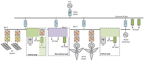
Figure 1.
AC microgrid architecture.
Figure 2 represents a typical structure of the DC-MG. Integration of the DC-MG into the main grid is provided by means of a bidirectional DC/AC converter system to facilitate power exchange between MG and the main grid. The RE-based DG units, ESS, and variable DC and AC loads are connected to DC buses through an AC/DC rectifier and DC/DC converter system. Two critical load buses with RE-based generators are presented in Figure 2. All the load-generation buses are connected to the point of common coupling or the main backbone of the system referred to as the DC common bus. The DC-MG offers several advantages over the AC-MG. First, simpler interface connections such as one stage DC/DC converter in a PV system and ESS and an AC/DC rectifier in the wind may reduce the number of power electronic devices, therefore enhancing the overall efficacy of the MG system. The DC-MG enables the provision of regulated DC voltage. Therefore, some DC loads can be connected directly to the DC bus. In grid-connected operation, synchronization is only required in the bidirectional DC/AC converter system, which connects the DC-MG to the grid. Moreover, these features bring simplification to the overall DC-MG control schemes.
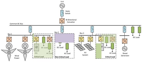
Figure 2.
DC microgrid architecture.
The primary consideration in the DC-MG is the bidirectional DC/AC converter, which facilitates a connection between the DC-MG and the main grid. This device handles the whole power flow from/to the main grid. Therefore, it requires highly rated power electronic devices. Moreover, the highly-rated bidirectional converter system may influence the system’s reliability. Another concern in the DC-MG is that the DC/AC converter system required to connect AC loads to the MG and DC load needs to be standardized. Thus, an additional power conversion stage is required to adjust the DC bus level or to generate the required AC voltage [8].
The AC-DC-MG configuration is composed of AC and DC buses with a bidirectional DC/AC converter, as depicted in Figure 3. In this typical configuration, the load/generation buses (bus 1 and 2) are connected via switches to the backbone of the network (i.e., common AC bus). This architecture combines the advantages of the AC-MG and DC-MG and compensates for the drawbacks of the system. Reliability is improved since there is a direct connection between the AC feeder and the grid. The DC feeder also provides simplification to the power electronic device structures. Various loads can be connected to the appropriate feeder. The AC load can be connected directly to the AC feeder or by means of DC/AC voltage converter in the DC feeder. The DC load can be directly connected to the DC feeder without a power converter. This configuration is suitable for MGs, which supply critical loads for specific purposes. Apart from the presented typical MG architectures, this work critically reviews the small-signal stability performance of islanding and grid-tied AC-MGs consisting of wind, PV, and BDG-based DG units in the next section.
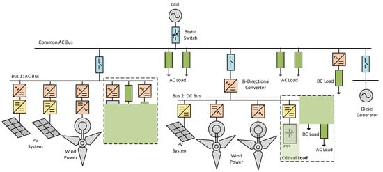
Figure 3.
AC-DC microgrid architecture.
3. Small-signal Model for Power Electronic Devices
Power electronic devices become the inevitable elements of RE-based DG units to convert the generated DC power to AC power. Moreover, this equipment is responsible for maintaining DG units’ output voltage and frequency at desired values. In addition, the power electronic devices’ fast-switching action enables the DG units’ ride-through. Therefore, a detailed mathematical model of each RE-based DG unit involving power electronic devices and associated controllers is required to obtain complete dynamic characteristics of the MG system.
A general mathematical model of power electronic switches in an AC/DC converter system was derived in [22]. The developed model considered the detailed modulation technique. Therefore, the proposed model is time-variant, nonlinear, and complex. To overcome these difficulties, the Fourier transform method was deployed to represent the switching actions of power electronic devices. The switching action was represented by modulation indices [23]. The steady-state operating point and dynamic response of the AC/DC converter could be determined separately from these models. Fourier transform’s eminent low- and high-frequency AC/DC converter models are on the switching frequency boundary. The high-frequency model is used to evaluate the harmonic components. The low-frequency model was linearized and transformed into a rotating reference frame to obtain a time-invariant steady-state and small-signal model.
Dynamic models of the single-phase and three-phase voltage source converter are presented in [12,24]. For the three-phase converter, modulation indices were treated as control variables of the converter, i.e., time-averaged switching duty cycles. The resulting small-signal model is time-variant due to the presence of periodic switching actions. Hence, transformation into a rotating reference frame must be conducted to obtain a time-invariant small-signal model, as depicted in [12,15,25]. A detailed representation of time-averaged switching components of the PWM control scheme has been studied and reported in [12]. Eigenvalue analysis displayed the movements of weak modes under small variations in modulation indices, indicating the dynamic characteristics of the converter system due to small variations of the control signal. Table 2 shows the overview of the power electronic devices model considered for small-signal stability analysis. From the table, it is evident that the power electronic devices are modelled with different complexities for small-signal stability assessment of the MG system. The trade-off between complexity and accuracy needs to be established under various uncertainties.
Table 2.
Small-signal model of power electric devices.
4. Small-Signal Stability in Microgrid
The MG stability can be categorized into transient, voltage, and small-signal stability issues [11,28]. The transient stability of the MG corresponds to the ability of the MG system to maintain stability after being subjected to significant disturbances such as a structural change in MG due to the outage of a particular DG unit, short circuit faults, and switching operation mode from grid-tied to islanding operation. The MG’s capability to maintain voltage within specified limits is known as voltage stability. Voltage instability concerns in MGs are highly correlated to reactive power balance conditions, dynamic load connections, the reactive power limit, and tap changer operations [29,30]. However, due to the small size and high R/X ratio, the voltage regulation of the MG could be influenced by the active power modulation in the MG. MGs are susceptible to small perturbations due to the cluster of RE-based DG units with fewer or no physical inertia features. The low physical inertia is mainly observed due to the wide deployment of power electronic devices in most RE-based DG units [11,31]. The lack of system damping in an MG potentially results in undamped oscillations when it is subjected to small disturbances [4,32,33,34]. The classification of stability in MGs and the typical reasons for each instability concern are depicted in Figure 4.
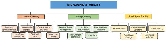
Figure 4.
Stability in microgrid [11,30].
Small-signal stability in MGs can arise from various sources such as continuous fluctuations of the RE-based system, the feedback controller, the small change in load, parameter variations, and a lack of damping due to the low-inertia characteristics of MG [11]. Smaller controller gain variations in a conventional power system with strong inertia features do not significantly affect the equilibrium point and stability margin [35]. Conversely, small changes in RE values, load demand, and system parameters involving controller gain in an MG system may lead to the undamped oscillatory condition under small disturbances [36,37,38,39]. Due to an assumption that the MG system is usually connected to a strong grid, small-signal instability could be one of the primary concerns for the islanded operation mode of the MG system [36,37,40,41,42,43,44]. This assumption is expected to change soon due to the reduction in the system strength in an interconnected transmission system with incremental penetration of the converter-based generator. In addition, inaccurate power sharing among DG units and high loading conditions within MGs potentially result in undamped oscillation, leading to instability [3].
Considering different assumptions involving different approaches to model power electronic devices to build the dynamic model of the MG system could provide diverse results corresponding to the source of small-signal stability in MGs. The critical modes might emerge from various state variables. In [41], a simplified model of converter-based DG units was developed to investigate the trajectories of the sensitive modes under a variation in active and reactive power controller gains and cut-off frequency. It was reported that the selection of a higher cut-off frequency improved the dynamic system responses. On the other hand, this frequency setting could lead to the avoidance of power signal ripples. Hence, it does not contribute to system instability.
A small-signal model of the MG system with three converter-based DG units is presented in [38,45]. It was observed that with the simplified model of switching devices and control systems, only the critical mode from the power controller’s state variable was identified. It was reported that the change in the power-sharing scheme, which was reflected in the change of droop gain values, affected the oscillatory stability of the MG. The variation in active power droop gain control introduced a significant impact on MG dynamic responses than the variation in reactive power droop gain. Therefore, low-frequency oscillations are mainly determined by the droop controllers of the DG unit.
The developed model in [38] was then improved with an additional phase-locked loop (PLL) block, as presented in [44]. The PLL contributes to the damping of the oscillatory modes, even though variation of droop gain control might cause instability issues to the MG systems. It is reported that the low-frequency eigenvalues are sensitive to a variation in droop gain and network configuration, while high-frequency modes are largely susceptible to inner controller gain. However, the dynamics from power electronic devices were disregarded due to the consideration of the ideal characteristics of the converter.
Small-signal stability analysis of electronically coupled and conventional DG units in MGs is presented in [32,36]. The obtained results in [32] suggest that the MG dynamic responses are influenced by system configuration and variability of generated power from each DG unit. Moreover, the ESS significantly enhanced the oscillatory stability margin of the MG by mitigating the instantaneous active/reactive power imbalance. In [36], a systematic approach and mathematical formulations for small-signal stability studies, including synchronous machines and converter-based DG units, are presented. It was revealed that the frequency deviation and oscillation on the electronically coupled DG unit occurred due to an increase in controller gains. Additional critical modes are observed when the MG operates in an islanded operation mode. The gain constant of PLL is identified as the source of the oscillatory mode. Governor control action in the synchronous machine provided frequency restoration for the MG system.
It is important to consider various loads and load parameter uncertainties for small-signal stability assessment of the MG systems [10,46,47,48]. Dynamic characteristics of converter-based DG units in MG under different load characteristics, such as inductive passive and active loads, are presented in [10,38,44,46,47,48]. The developed small-signal model in [38] was employed in [10,46] to investigate the influence of active loads on the oscillatory stability of MGs. Incorporating an active load in the small-signal stability model of autonomous MG operation could introduce small stability/instability concerns, specifically when interaction happens between the active load and converter-based DG unit [10]. Moreover, the large gain setting of the active load voltage controller leads to instability conditions. It was clearly seen that active load severely affects the oscillatory stability of the MG. Deterioration of a small-signal stability margin was monitored when a dynamic load such as an induction motor (IM) was connected to the MG [47,48]. Low-frequency oscillation of electromechanical modes of a large IM resulted in undesirable dynamic responses and poor small-signal stability performance of the MG in islanded operation mode [48]. The presence of an IM might cause an admittance mismatch between the IM load and the MG. This mismatch could destabilize the islanding operation due to the coupling between the IM and the converter. An active compensation technique based on the Nyquist stabilization criterion has been proposed to maintain the stability of the system. This method provides simplicity and positively influences the power-frequency oscillation of DG units in isolated operations. A two-DOF (degrees of freedom) active damping control algorithm was proposed in [47] to mitigate low-frequency oscillation. The transient supplementary power angle and voltage magnitude signals are effectively used to damp the MG frequency and voltage oscillations without affecting the steady-state power-sharing characteristics.
Different dynamic responses from DG units could be observed when various RE-based power generators are integrated into an MG system. Those distinct dynamic characteristics cannot be captured using the simplified model of MG systems. However, in most studies, power electronic devices in DG units are usually presented as ideal voltage/current sources [10,38,45,49]. Therefore, it is difficult to monitor the typical dynamic characteristics of different power electronic device architectures in a particular DG unit [15,36,37]. The detailed MG model was primarily developed in [40]. However, the control systems were not considered in those presented models. Moreover, in an MG system with a cluster of DG units, a sophisticated MG control algorithm introduces more nonlinear effects on modal behaviour, potentially leading to interaction among sensitive modes [6,7,50].
A more detailed model of an RE-based DG unit provides a complete representation of the small-signal stability performance of MG systems. In [28,39,51], a detailed MG system consisting of a detailed model of a wind (Type 4 with AC-DC-AC converter), PV (two-stages with DC-DC and DC-AC converter), and diesel generator with LCL filters and generic controllers is presented. It was reported that the risk of instability could be increased from gain controller adjustment. The DC link and the voltage and current controller gains could also affect the MG system’s small-signal stability. The critical modes vary significantly with the variation in associated droop and gain of the controllers.
The small-signal stability performance of the DC MG is presented in [33,34]. The DC MG is modelled using an average model of the parallel DC-DC converter. Impedance analysis was performed in a system with parallel converters. In [49,52], a small-signal model of a DC/AC converter with static droop characteristics (combined with an adaptive transient droop function) was considered. Similar to the AC MG, in the DC MG, there are critical modes. These modes are characterized by low-frequency modes, mainly determined by the droop controllers of the DG unit. It was also reported that oscillatory conditions depend on the parameters of converters and controllers, line impedance, and load [53]. Low-frequency modes are dictated mainly by the power-sharing controllers and the power filters [49,52]. Load proportion could significantly affect the small-signal stability performance of the DC MG. Trajectories of eigenvalues suggested that a high portion of constant power load (CPL) could adversely affect the damping of the DC MG due to its negative impedance characteristic [54,55,56,57,58]. Conversely, the constant resistive load (CRL) increases the damping characteristics of the MG. Table 3 summarizes the key technical aspects related to the small-signal stability of the MG.
Table 3.
Overview of small-signal stability in MG.
The uncertainty of renewable sources also contributes to the dynamic behaviour of the MG system. Critical modes within the MG might fluctuate randomly with uncertainties associated with renewable sources. In [59], the trajectories of critical modes under uncertain wind speed conditions in a wind–diesel MG system were investigated. It was observed that at a higher wind speed variation, the small-signal stability performance of the MG deteriorated severely. The dynamic performance also deteriorated considerably when each wind-based DG unit in MG was subjected to different wind speeds compared to a similar wind speed regime. The effects of mixture uncertainties from wind speed and solar irradiance on small-signal stability of MG systems are presented in [6,60,61,62]. Conventional and copula methods were implemented in estimating the probability density function (pdf) of wind speed and solar irradiance, considering the possible correlation between those two renewable sources for small-signal stability assessment.
5. Interaction and Resonance in Microgrid
5.1. Interaction in Power System
Modern power systems mostly operate under stressed situations due to the variations of load profiles, heavy transmission line loading conditions, and economy of operation [63]. Moreover, increasing penetration of RE-based power generation also introduces novel challenges to dynamic system behaviour, potentially leading to interactions. The power system interaction is the interaction that emerges in the different modes in power systems. Power system interactions may occur due to coupling among torsional modes, control modes of compensator devices, electromechanical modes of synchronous generators, control modes of RE-based DG units, and harmonics components [64]. The interactions introduce detrimental effects on system stability and power quality, such as low stability margin, reduced power transfer capability, and amplification of harmonic distortions. The classification of interactions in the power system is depicted in Figure 5.
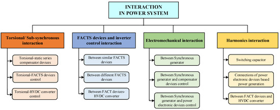
Figure 5.
Interaction in power system.
Subsynchronous resonance (SSR) occurs when the critical modes from generator shafts swing each other and interact with the external network. When the power system is subjected to disturbances such as the switching action of series compensator devices, the subsynchronous resonance can be excited. The torsional resonance is characterized by oscillatory frequency in the range of 10–50/60 Hz [65]. Moreover, if the initial magnitude of the torque in the shaft is high, it can lead to fatigue of the shaft [66,67,68].
The SSR between the torsional modes of the synchronous generator and the static series capacitor is investigated in [66,67,68,69,70,71,72]. The frequency spectrum analysis method presented in [70] found that SSR risk may occur at each given compensation ratio. The damping coefficient of the electrical system reaches its highest negative values when the subsynchronous torque frequency is equal to or close to one of the natural frequencies of the generator shaft. The highest negative values of the damping coefficient indicate a risk of instability correlated to undamped oscillatory conditions. It was observed that the impacts of SSR on the stability of a multimachine power system are highly correlated to the closeness of the electrical frequency of the series capacitor to the torsional frequency. Moreover, the proximity between the series compensator and synchronous machines and the size of the series capacitor are the main factors that influence the strength of the SSR and its impact on power system stability. Due to the compact and small size of the MG with less and no synchronous generation and series compensators, the SSR behaviour observed in the large power system may not be noticed in the MG. However, there are other potential sources of SSR in the MG.
The interaction between the HVDC converter controller and a nearby generating unit was analyzed in [73,74,75,76]. The lower value of AC transmission line reactance, DC link loading conditions and converter firing angle reduced the risk of instability. On the other hand, the effect of the current controller at the HVDC converter station potentially introduced negative damping on the nearby generator unit. According to sensitivity analysis, it was reported that a system with higher loading, DC power transfer, or weak AC tie-line is more susceptible to the subsynchronous torsional interaction. The medium-voltage DC MG coupling with the AC MG could experience this phenomenon.
As the capacity of a transmission network increases in proportion to the increase in load demand and power generation, several FACTS devices and power electronic devices are employed to optimize the loading capacity of the transmission network and maintain system stability. However, the deployment of many FACTS and power electronic devices could cause the interaction between controllers of those devices, resulting in a detrimental effect on system stability. The interaction between FACTS and converter controllers can be categorized into the interaction between controllers of similar FACTS devices, between controllers of different FACTS devices, and between FACTS and HVDC converter controllers [65]. Due to the small and compact size and high R/X ratio, FACTS devices are very unlikely to be used in MGs. Therefore, this interaction is less likely to occur in MG systems.
Dynamic coupling between several SVCs in a radial weak power system is presented in [77,78,79]. The interaction between SVCs depends on the transmission line’s length, effective short circuit ratio (ESCR), and the setting of controller gain of SVCs. More severe interaction was evident in the lower ESCR and higher controller gain settings. Without proper coordination control among SVCs, the interaction between SVCs could lead to large transience in voltage profiles. Furthermore, the controller gain in front of the meter battery could generate a similar interaction. Moreover, more severe effects could occur under heavy loading conditions, such as voltage sags of up to 40%. An investigation of the interaction between TCSC and SVC is presented in [80]. Loading conditions and electrical distance are the main factors affecting the coupling between TCSC and SVC. The severe impact of interaction was monitored at higher loading conditions and shorter electrical distances. Interaction between HVDC and FACT devices may happen due to a change in DC power. Relative gain array (RGA) analysis suggested that the TCSC is more sensitive to a change in DC power, indicating a stronger connection between TCSC and HVDC converter control, while only small interaction between SVC and HVDC was observed [81,82]. This phenomenon could be observed in DC/AC-coupled MG systems.
Another type of interaction, such as among electromechanical modes and between electromechanical modes of synchronous generators and control modes of power electronic devices, may lead to instability in a power system. The electromechanical modes of synchronous generators comprise local and interarea modes, which are typically characterized by low oscillatory frequencies in the range of 0.7–2.5 Hz and 0.1–0.7 Hz, respectively [83]. Interactions between electromechanical modes under a stressed condition are presented in [84,85,86,87]. The nonlinear interaction between local modes from a two-area power system can substantially affect the system’s dynamic performance, altering the oscillatory stability of a conventionally designed system. Near the resonance point, the interacting modes deviated oppositely, leading to deterioration or even unstable conditions. Furthermore, the weak coupling between local modes in a two-area power system emerges due to high transfer impedance of the transmission line and the changes in power flow direction. Due to the absence of a long tie-line and several synchronous generators in the MG systems, the electromechanical oscillation in the frequency range of the transmission system is not common in the MG systems. However, some recent works have reported the oscillation in the weak grid in the range of electromechanical frequency due to the converter controllers. This same phenomenon could be observed in the MG system due to the tuning of the controllers.
The oscillation frequency in the range of 15 Hz and more is classified as harmonic stability [65]. However, the switching dynamics of the compensators and power electronic devices can generate harmonics and interact with system impedance, causing higher distortion in system current and voltage. For example, harmonic interaction between the HVDC converter and AC system is presented in [88,89,90]. Moreover, with the increasing penetration of electronically coupled DG units, harmonic distortions generated by switching actions of power electronic devices have increased proportionally. Consequently, a higher risk of harmonic interaction between the interfacing power electronic devices is possible.
5.2. Interaction in MG
Implementation of power electronic devices and complex control algorithms within MGs introduces novel challenges in terms of small-signal stability and possible resonance among the DG units. The occurrence of interaction in a low-inertia system such as an MG may worsen the stability margin of the system, leading to an undamped oscillatory condition, which eventually results in instability. The interaction within the MG is characterized by various frequency ranges from low oscillatory frequency between 1–2 Hz, to subsynchronous frequency, to higher frequency ranges around harmonic frequencies. Low- and high-frequency disturbances can be a result of source uncertainties and circuit architectures of the MG, respectively [91,92]. Moreover, the usage of unbalanced and nonlinear loads augments the harmonic resonance [93,94].
Under an autonomous mode of operation, interaction or resonance phenomenon is very crucial since it can severely affect the quality of supply, worsen distortion, reduce damping, and eventually lead to instability of the whole system [95,96]. Low-frequency interaction among DG units within MG is presented in [28,51]. The interaction among critical modes from RE-based DG units corresponding to the variation of the power-sharing scheme in MG has been monitored. Three identification procedures—eigen-trajectories, cross-participation factor (CPF), and modal interaction index (MII)—were proposed to identify the occurrence of interaction. Typical eigenvalue movements around the interaction point were monitored. It can be observed that the interacting modes approach each other and coincide at a particular point. Around the interaction point, the engaged modes were very susceptible. Under small disturbances, the interacting modes would move to the opposite direction, resulting in a significant reduction in damping, which might lead to instability.
In grid-tied operation, various power injection levels from the MG may result in modal interaction between the MG and the rest of the system. The resonance phenomenon potentially emerges when the modes align both in damping and frequency of oscillation [6]. The number of connected converter-based DG units in a grid influenced the resonance of the power system. If the total installed capacity of the grid-connected converters is approximately equal to or greater than conventional synchronous generators, the interaction between generators and load is possibly observed in the system [97]. The impact of various converter-based generators on harmonic resonance is reported in [98,99]. The interaction between converter-based DG units within MG and the distribution network is presented in [100]. Interaction between DC MG and line impedance is reported in [96,101]. The DC voltage collapse could be observed due to resonance in the MG system. This could be minimized with proper control tuning.
Specific control algorithms of voltage or current source converters are necessary to minimize the harmonic resonance propagation. An improved virtual impedance control method is proposed for the virtual capacitor and damping resistor. The nonlinear virtual capacitor can be used to compensate for the harmonic voltage drop. In contrast, virtual resistor damping is mainly responsible for MG resonance damping. Investigation of possible interaction in a grid-tied paralleled converter-based MG is presented in [102]. The resonance problem in paralleled converter-based DG units emerges from the converter output LCL filter and interaction among converters. A high-order LCL filter is essential to suppress the high-order harmonic component from the switching action of the converter. However, the filter has inherent resonance characteristics that amplify the background harmonics, resulting in more distorted current and voltage, and even instability [97,103]. Furthermore, the converter interactions excite complex resonances at various frequencies, resulting in a severely distorted line current and deterioration of MG damping. However, many of these works have used naive and synthesized systems for assessment. Therefore, the proposed algorithms and controls need to be tested in a realistic system under various uncertainties. The overview of resonance/interaction within MGs is presented in Table 4.
Table 4.
Overview of interaction in MG.
6. Future Research
Critical reviews of the dynamic characteristics of RE-based generators, their components, small-signal stability performance and interaction in the MG environment have been presented in this paper. It addresses possible small-signal instability and resonance issues within MG, leading to the identification of future research areas.
6.1. Dynamic Model of MG
Many approaches have been implemented to represent a complete dynamic model of the MG. However, they have yet to obtain a standardized MG model that provides a comprehensive picture of the MG system’s dynamic behaviour and small-signal stability performance. The complicacy increased with the detailed modelling. The numerical stability issues can be observed with the detailed model. Furthermore, various converters from different vendors can be used in MG modelling. Currently, most of the studies use the generic model of converters for MG stability studies. Therefore, a suitable trade-off mechanism must be established for the researchers and the planning engineers to select the appropriate models.
6.2. Uncertainties in MGs
Uncertainty is a typical concern in MG operations. With a dominant portion of RE-based DG units and emerging loads (i.e., EV and other electronic loads), the MG’s uncertainties are more complex than the traditional power systems. An MG system has to deal with source intermittencies and load uncertainties. The common uncertainty modelling in MGs uses a probabilistic model of renewable source and load. However, only uncertainties in sources have been taken into account in most of the previous research. In order to provide a more realistic scenario for MG operation, the stochastic model of renewable sources and load should be appropriately considered in the modelling and analysis. Furthermore, advancement in uncertainty modelling and representation is required.
6.3. Resonance Assessment in MGs
Autonomous and grid-tied operation of MGs leads to the occurrence of interactions such as interaction among DG units within the MG, the resonance between the MG and series compensator devices, and coupling between LCL filters of DG units and line impedance. Several algorithms are presented in the literature to identify the resonance such as impedance and frequency analysis, trajectories of the engaged eigenvalues, cross-participation factor, and an index, known as the modal interaction index (MII). It is essential to assess the resonance phenomenon to quantify the strength of resonance and risk of instability and appropriate mitigation or prevention. A lack of understanding of the resonance in the MG environment requires more research to propose an index that can identify the occurrence and the strength of the resonance.
7. Conclusions
Renewable energy-based microgrid (MG) systems are becoming significantly popular in providing electric power to remote and regional customers with poor reliability of supply. On the other hand, the MG must be able to handle the intermittency and uncertainty associated with renewable sources and emerging new loads. Moreover, the inertia-less characteristics of RE-based DG units and sophisticated power electronic control algorithms within MGs potentially introduce oscillatory problems when the MG is subjected to small disturbances. Moreover, the interaction or resonance among DG units, compensator devices, line impedance, and loads could introduce a serious instability concern in MGs. Therefore, a generic MG model incorporating detailed dynamic characteristics of RE-based DG units and load and control systems are required to assess a complete picture of MG dynamics. The reviews also found that more research needs to be conducted to investigate the interaction phenomenon in MGs, including a comprehensive index that can quantify the resonance in power electronic-based MG systems.
Funding
This research received no external funding.
Conflicts of Interest
The authors declare no conflict of interest.
References
- IRENA (International Renewable Energy Agency). World Energy Transitions Outlook 2022: 1.5 °C Pathway; International Renewable Energy Agency: Abu Dhabi, United Arab Emirates, 2022. [Google Scholar]
- IRENA (International Renewable Energy Agency). Installed Capacity Trends of Wind Power. Available online: https://www.irena.org/wind (accessed on 26 November 2022).
- Farrokhabadi, M.; Canizares, C.A.; Simpson-Porco, J.W.; Nasr, E.; Fan, L.; Mendoza-Araya, P.A.; Tonkoski, R.; Tamrakar, U.; Hatziargyriou, N.D.; Lagos, D.; et al. Microgrid Stability Definitions, Analysis, and Examples. IEEE Trans. Power Syst. 2020, 35, 13–29. [Google Scholar] [CrossRef]
- Olivares, D.E.; Mehrizi-Sani, A.; Etemadi, A.H.; Canizares, C.A.; Iravani, R.; Kazerani, M.; Hajimiragha, A.H.; Gomis-Bellmunt, O.; Saeedifard, M.; Palma-Behnke, R.; et al. Trends in Microgrid Control. IEEE Trans. Smart Grid 2014, 5, 1905–1919. [Google Scholar] [CrossRef]
- Rojas, A.; Rousan, T. Microgrid Control Strategy. IEEE Power Energy Mag. 2017, 15, 72–79. [Google Scholar] [CrossRef]
- Krismanto, A.; Mithulananthan, N.; Setiadi, H.; Setyawan, E.; Abdillah, M. Impacts of grid-tied microgrid on stability and interaction of power systems considering RE uncertainties. Sustain. Energy Grids Netw. 2021, 28, 100537. [Google Scholar] [CrossRef]
- Krismanto, A.; Mithulananthan, N.; Krause, O. Microgrid Impact on Low Frequency Oscillation and Resonance in Power System. In Proceedings of the ISGT Asia Pacific 2016, Melbourne, Australia, 28 November–1 December 2016; Available online: https://164.248.212.185/Microgrid-Impact-on-Low-Frequency-Oscillation.pdf (accessed on 26 November 2022).
- Patrao, I.; Figueres, E.; Garcerá, G.; González-Medina, R. Microgrid architectures for low voltage distributed generation. Renew. Sustain. Energy Rev. 2015, 43, 10. Available online: https://196.160.120.134/Microgrid-architectures-for-low-voltage-distri.pdf (accessed on 26 November 2022). [CrossRef]
- Shuai, Z.; Sun, Y.; Shen, Z.J.; Tian, W.; Tu, C.; Li, Y.; Yin, X. Microgrid stability: Classification and a review. Renew. Sustain. Energy Rev. 2016, 58, 167–179. Available online: https://84.101.190.255/Microgrid stability Classification and a revie.pdf (accessed on 26 November 2022). [CrossRef]
- Bottrell, N.; Prodanovic, M.; Green, T. Dynamic Stability of a Microgrid with an Active Load. IEEE Trans. Power Electron. 2013, 28, 5107–5119. Available online: https://215.254.111.145/Dynamic-Stability-of-a-Microgrid-with.pdf (accessed on 26 November 2022). [CrossRef]
- Majumder, R. Some Aspects of Stability in Microgrids. IEEE Trans. Power Syst. 2013, 28, 3243–3252. [Google Scholar] [CrossRef]
- Rahim, N.A.; Quaicoe, J.E. Small Signal Model and Analysis of a Mulitple Feedback Control Scheme for Three Phase Voltage Source UPS Inverter. In Proceedings of the Power Electronics Specialist Conference, Baveno, Italy, 23–27 June 1996; pp. 188–194. Available online: https://211.213.252.125/Small-Signal-Model-and-Analysis-of-A-Multiple.pdf (accessed on 26 November 2022).
- Kaviani, A.; Yen, K.; Mirafzal, B. Dynamic Model of Three Phase Current Source Boost Inverter for Stand Alone Application. In Proceedings of the Applied Power Electronics Conference and Exposition, Orlando, FL, USA, 5–9 February 2012; pp. 218–224. Available online: https://0620850699/Dynamic-Model-of-Three-Phase-Current-Source.pdf (accessed on 26 November 2022).
- Mirafzal, B.; Saghaleini, M.; Kaviani, A.K. An SVPWM-Based Switching Pattern for Stand Alone and Grid Connected Three Phase Single Stage Boost Converter. IEEE Trans. Power Electron. 2010, 26, 10. Available online: https://210.130.108.55/An-SVPWM-Based-Switching-Pattern-for.pdf (accessed on 25 November 2022).
- Nimpitiwan, N.; Kaitwanidvilai, S. Static Output Feedback Robust Loop Shaping Control for Grid Connected Inverter using Genetic Algorithms. Int. J. Innov. Comput. Inf. Control 2012, 8, 6081–6093. Available online: https://100.232.110.74/Static-Output-Feedback-Robust-loop-Shaping.pdf (accessed on 19 November 2022).
- Hiti, S.; Boroyevich, D. Small Signal Modelling of Three Phase PWM Modulators. In Proceedings of the Power Electronics Specialists Conference, Baveno, Italy, 23–27 June 1996; IEEE Press: New York, NY, USA, 1996; Volume 1, pp. 550–555. Available online: https://218.220.103.56/Small-Signal-Modeling-of-Three-phase-PWM-Modul.pdf (accessed on 15 November 2022).
- Middlebrook, R.; Cuk, S. A General Unified Approach to Modelling Switching-Converter Power Stages. In Proceedings of the Power Electronics Specialists Conference, Cleveland, OH, USA, 8–10 June 1976; p. 14. [Google Scholar]
- Zeng, Z.; Yang, H.; Zhao, R. Study on small signal stability of microgrids: A review and a new approach. Renew. Sustain. Energy Rev. 2011, 15, 4818–4828. [Google Scholar] [CrossRef]
- Wang, S.; Su, J.; Yang, X.; Du, Y.; Tu, Y.; Xu, H. A review on the small signal stability of microgrid. In Proceedings of the 2016 IEEE 8th International Power Electronics and Motion Control Conference (IPEMC-ECCE Asia), Hefei, China, 22–26 May 2016; pp. 1793–1798. [Google Scholar] [CrossRef]
- Maitra, A.; Pratt, A.; Hubert, T.; Wang, D.; Prabakar, K.; Handa, R.; Baggu, M.; McGranaghan, M. Microgrid Controllers: Expanding Their Role and Evaluating Their Performance. IEEE Power Energy Mag. 2017, 15, 41–49. [Google Scholar] [CrossRef]
- Justo, J.J.; Mwasilu, F.; Lee, J.; Jung, J.-W. AC-Microgrid versus DC-Microgrid with distributed energy resources: A review. Renew. Sustain. Energy Rev. 2013, 24, 387–405. Available online: https://218.58.112.154/AC-microgridsversusDC-microgridswithdistribute.pdf (accessed on 15 November 2022). [CrossRef]
- Wu, R.; Dewan, S.; Slemon, G. A PWM AC-to-DC Converter with Fixed Switching Frequency. IEEE Trans. Ind. Appl. 1990, 26, 6. Available online: https://0803104022/A PWM-AC-to-DC-Converter-with-Fixed-Switching.pdf (accessed on 10 November 2022). [CrossRef]
- Wu, R.; Dewan, S.B.; Slemon, G.R. Analysis of an AC-to-DC Voltage Source Converter using PWM with Phase and Amplitude Control. IEEE Trans. Ind. Appl. 1991, 27, 12. Available online: https://0878116090/Analysis of an ac-to-dc Voltage Source 1991.pdf (accessed on 20 October 2022). [CrossRef]
- Rahim, N.; Quaicoe, J. Multiple Feedback Loop Control Strategy for Single Phase Voltage Source Inverter. In Proceedings of the 1994 Power Electronics Specialist Conference, Taipei, Taiwan, 20–25 June 1994; Volume 2, pp. 958–964. Available online: https://0460809759/Multiple-Feedback-Loop-Control-Strategy-for.pdf (accessed on 20 October 2022).
- Rese, L.; Costa, S.; Silva, A.S. Enhanced Modeling and Control of VSIs in Microgrids Operating in Grid-Connected Mode. In Proceedings of the 2012 IEEE PES Innovative Smart Grid Technologies (ISGT), Washington, DC, USA, 16–20 January 2012; pp. 1–8. Available online: https://121.76.110.230/Enhanced-Modeling-and-Control-of-VSIs-in.pdf (accessed on 20 October 2022).
- Dijk, V.E.; Spruijt, H.J.N.; O’Sullivan, D.M.; Klassens, J.B. PWM-Switch Modeling of DC-DC Converters. IEEE Trans. Power Electron. 1995, 10, 7. Available online: https://101.204.102.156/PWM-Switch-Modeling-of-DC-DC-Converters.pdf (accessed on 15 November 2022).
- Erickson, R.W.; Maksimovic, D. Fundamental of Power Electronics Second Edition; Kluwer Academic Publisher: Drive Norwell, MA, USA, 2001. [Google Scholar]
- Krismanto, A.; Mithulananthan, N.; Krause, O. Small Signal Stability of Renewable Energy based Microgrid in Autonomous Operation. Sustain. Energy Grid Netw. J. 2018, 13, 134–147. [Google Scholar] [CrossRef]
- Parol, M.; Rokicki, Ł. Voltage stability in low voltage microgrids in aspects of active and reactive power demand. Arch. Electr. Eng. 2016, 65, 19. [Google Scholar] [CrossRef]
- Schiffer, J.; Seel, T.; Raisch, J.; Sezi, T. Voltage Stability and Reactive Power Sharing in Inverter-Based Microgrids with Consensus-Based Distributed Voltage Control. IEEE Trans. Control Syst. Technol. 2016, 24, 96–109. [Google Scholar] [CrossRef]
- Wang, X.; Guerrero, J.M.; Blaabjerg, F.; Chen, Z. A review of power electronics based microgrids. J. Power Electron. 2012, 12, 181–192. [Google Scholar] [CrossRef]
- Tang, X.; Deng, W.; Qi, Z. Investigation of the Dynamic Stability of Microgrid. IEEE Trans. Power Syst. 2014, 29, 698–706. Available online: https://204.159.118.22/Investigation-of-the-Dynamic-Stability-of-Micr.pdf (accessed on 20 October 2022). [CrossRef]
- Hamzeh, M.; Ghafouri, M.; Karimi, H.; Sheshyekani, K.; Guerrero, J.M. Power Oscillations Damping in DCMicrogrids. IEEE Trans. Energy Convers. 2016, 31, 970–980. Available online: https://154.4.106.88/Power-Oscillations-Damping-in-DC-Microgrids.pdf (accessed on 20 October 2022). [CrossRef]
- Rashidirad, N.; Hamzeh, M.; Sheshyekani, K.; Afjei, E. A Simplified Equivalent Model for the Analysis of Low-Frequency Stability of Multi-Bus DC Microgrids. IEEE Trans. Smart Grid 2017, 9, 6170–6182. Available online: https://177.70.202.67/A Simplified Equivalent Model for the Analysis.pdf (accessed on 20 October 2022). [CrossRef]
- Dobson, I.; Zhang, J.; Greene, S.; Engdahl, H.; Sauer, P.W. Is Strong Modal Resonance a Precursor to Power System Oscillations? IEEE Trans. Circuit Syst. Fundam. Theory Appl. 2001, 48, 340–349. Available online: https://99.93.194.209/Is-Strong-Modal-Resonance-a-Precursor-to-Power.pdf (accessed on 20 October 2022). [CrossRef]
- Katerei, F.; Iravani, M.R.; Lehn, P.W. Small-signal dynamic model of a micro-grid including conventional and electronically interfaced distributed resources. IET Gen. Transm. Distrib. 2007, 1, 369–378. Available online: https://207.62.183.137/Small-signal dynamic-model-of-a-micro-grid.pdf (accessed on 20 October 2022). [CrossRef]
- Kroutikova, N.; Hernandez-Aramburo, C.A.; Green, T.C. State-space model of grid-connected inverters under current control mode. IET Electr. Power Appl. 2007, 1, 329–338. [Google Scholar] [CrossRef]
- Pogaku, N.; Prodanovic, M.; Green, T.C. Modeling, analysis and testing of autonomous operation of an inverter-based microgrid. IEEE Trans. Power Electron. 2007, 22, 613–625. [Google Scholar] [CrossRef]
- Krismanto, A.; Mithulananthan, N.; Lee, K.Y. Comprehensive Modelling and Small Signal Stability Analysis of RES-based Microgrid. In Proceedings of the 9th IFAC Symposium on Control of Power and Energy Systems CPES, New Delhi, India, 9–11 December 2015; Elsevier: Amsterdam, The Netherlands, 2015; pp. 282–287. Available online: https://204.222.114.95/Comprehensive-Modelling-and-Small-Signal-Stabi.pdf (accessed on 20 October 2022).
- Lopes, J.A.P.; Moreira, C.L.; Madureira, A.G. Defining control strategies for microgrids islanded operation. IEEE Trans. Power Syst. 2006, 21, 916–924. [Google Scholar] [CrossRef]
- Coelho, E.; Cortizo, P.C.; Garcia, P.F.D. Small-signal stability for parallel-connected inverters in stand-alone AC supply systems. IEEE Trans. Ind. Appl. 2002, 38, 533–542. [Google Scholar] [CrossRef]
- Karimi, H.; Nikkhajoei, H.; Iravani, R. Control of an Electronically-Coupled Distributed Resource Unit Subsequent to an Islanding Event. IEEE Trans. Power Deliv. 2008, 23, 493–500. Available online: https://72.111.107.171/Control of an Electronically-Coupled Distribut.pdf (accessed on 20 October 2022). [CrossRef]
- Etemadi, A.H.; Iravani, R. Eigenvalue and Robustness Analysis of a Decentralized Voltage Control Scheme for an Islanded Multi-DER Microgrid. In Proceedings of the Power and Energy Society General Meeting, San Diego, CA, USA, 22–26 July 2012; pp. 1–8. Available online: https://78.108.109.189/Eigenvalue-and-Robustness-Analysis-of-a.pdf (accessed on 20 October 2022).
- Rasheduzzaman, M.; Mueller, J.A.; Kimball, J.W. An Accurate Small-Signal Model of Inverter-Dominated Islanded Microgrids Using dq Reference Frame. IEEE J. Emerg. Sel. Top. Power Electron. 2014, 2, 1070–1080. Available online: https://205.228.117.138/An Accurate Small-Signal Model of Inverter-.pdf (accessed on 20 October 2022). [CrossRef]
- Barklund, E.; Pogaku, N.; Prodanovic, M.; Hernandez-Aramburo, C.; Green, T.C. Energy Management in Autonomous Microgrid Using Stability-Constrained Droop Control of Inverters. IEEE Trans. Power Electron. 2008, 23, 2346–2351. Available online: https://174.250.184.177/Energy-Management-in-Autonomous-Microgrid-Usin.pdf (accessed on 20 October 2022). [CrossRef]
- Bottrell, N.; Green, T.C. Control and Modelling for Power Electronics. 2012, pp. 1–8. Available online: https://161.141.109.80/Modeling-Microgrids-with-Active-Loads.pdf (accessed on 20 October 2022).
- Kahrobaeian, A.; Mohamed, Y.-R.I. Analysis and Mitigation of Low-Frequency Instabilities in Autonomous Medium-Voltage Converter-Based Microgrids with Dynamic Loads. IEEE Trans. Ind. Electron. 2014, 61, 1643–1658. Available online: https://173.217.114.17/Analysis and Mitigation of Low-Frequency.pdf (accessed on 20 October 2022). [CrossRef]
- Radwan, A.; Mohamed, Y.-R. Stabilization of Medium-Frequency Modes in Isolated Microgrids Supplying Direct Online Induction Motor Loads. IEEE Trans. Smart Grid 2014, 5, 358–370. Available online: https://143.157.116.113/Stabilization-of-Medium-Frequency-Modes.pdf (accessed on 20 October 2022). [CrossRef]
- Mohamed, Y.-R.I.; El-Saadany, E.F. Adaptive Decentralized Droop Controller to Preserve Power Sharing Stability of Paralleled Inverters in Distributed GenerationMicrogrids. IEEE Trans. Power Electron. 2008, 23, 2806–2816. Available online: https://75.42.185.218/Adaptive-Decentralized-Droop-Controller-to-Pre.pdf (accessed on 20 October 2022). [CrossRef]
- Leitner, S.; Yazdanian, M.; Mehrizi-Sani, A.; Muetze, A. Small-Signal Stability Analysis of an Inverter-Based Microgrid with Internal Model-Based Controllers. IEEE Trans. Smart Grid 2018, 9, 5393–5402. [Google Scholar] [CrossRef]
- Krismanto, A.U.; Nadarajah, M. Identification of Modal Interaction and Small Signal Stability in Autonomous Microgrid Operation. IET Gener. Transm. Distrib. 2017, 12, 247–257. [Google Scholar] [CrossRef]
- Krismanto, A.U.; Mithulananthan, N.; Lomi, A. Dynamic droop control in microgrid for stability enhancement considering RES variation. In Proceedings of the 2017 IEEE PES Innovative Smart Grid Technologies Conference Europe (ISGT-Europe), Torino, Italy, 26–29 September 2017; pp. 1–6. [Google Scholar] [CrossRef]
- Karimi, A.; Pirayesh, A.; Aghdam, T.S.; Ajalli, M. DC micro grid small signal stability analysis. In Proceedings of the 18th Electric Power Distribution Conference, Kermanshah, Iran, 30 April–1 May 2013; pp. 1–4. [Google Scholar] [CrossRef]
- Zhao, F.; Li, N.; Yin, Z.; Tang, X. Small-signal modeling and stability analysis of DC microgrid with multiple type of loads. In Proceedings of the 2014 International Conference on Power System Technology, Chengdu, China, 20–22 October 2014; pp. 3309–3315. [Google Scholar] [CrossRef]
- Kwasinski, A.; Onwuchekwa, C.N. Dynamic Behavior and Stabilization of DC Microgrids with Instantaneous Constant-Power Loads. IEEE Trans. Power Electron. 2011, 26, 822–834. [Google Scholar] [CrossRef]
- Cespedes, M.; Xing, L.; Sun, J. Constant-Power Load System Stabilization by Passive Damping. IEEE Trans. Power Electron. 2011, 26, 1832–1836. [Google Scholar] [CrossRef]
- Liu, S.; Zhu, W.; Cheng, Y.; Xing, B. Modeling and small-signal stability analysis of an islanded DC microgrid with dynamic loads. In Proceedings of the 2015 IEEE 15th International Conference on Environment and Electrical Engineering (EEEIC), Rome, Italy, 10–13 June 2015; pp. 866–871. [Google Scholar] [CrossRef]
- Liu, Z.; Su, M.; Sun, Y.; Han, H.; Hou, X.; Guerrero, J.M. Stability analysis of DC microgrids with constant power load under distributed control methods. Automatica 2018, 90, 62–72. [Google Scholar] [CrossRef]
- Krismanto, A.; Mithulanthan, N. Probabilistic Small Signal Stability Analysis of Autonomous Wind-Diesel Microgrid. In Proceedings of the ISGT Asia Pacific 2017, Auckland, New Zealand, 4–7 December 2017. [Google Scholar]
- Krismanto, A.U.; Mithulananthan, N.; Kamwa, I. Oscillatory stability assessment of microgrid in autonomous operation with uncertainties. IET Renew. Power Gener. 2018, 12, 494–504. [Google Scholar] [CrossRef]
- Xu, X.; Lin, T.; Zha, X. Probabilistic Analysis of Small Signal Stability of Microgrid Using Point Estimate Method. In Proceedings of the Sustainable Power Generation and Supply 2009 SUPERGEN’09, Nanjing, China, 6–7 April 2009; Available online: https://0966507968/Probabilistic Analysis of Small Signal Stabili.pdf (accessed on 20 November 2022).
- Krismanto, A.; Nadarajah, M.; Lomi, A.; Setiadi, H.; Abdillah, M. Copula-Monte Carlo Based Probabilistic Oscillatory Stability Analysis of Microgrid. Int. J. Intell. Eng. Syst. 2021, 14, 479–491. [Google Scholar] [CrossRef]
- Hossain, J.; Pota, H.R. Robust Control for Grid Voltage Stability: High Penetration of Renewable Energy; Springer Science: Singapore, 2014. [Google Scholar]
- Kim, H.J.; Nam, T.; Hur, K.; Chang, B.; Chow, J.H.; Entriken, R. Dynamic interactions among multiple FACTS controllers—Survey. In Proceedings of the 2011 IEEE Power and Energy Society General Meeting, Detroit, MI, USA, 24–28 July 2011; pp. 1–8. [Google Scholar] [CrossRef]
- Singh, B.; Sharma, N.K.; Tiwari, A.N. Coordinated control and interactions between FACTS controller in multi-machine power system environment: An Overview and Issues. In Proceedings of the Fifteenth National Power Systems Conference (NPSC), Mumbai, India, 16–18 December 2008. [Google Scholar]
- Padiyar, K.R.; Kulkarni, A.M. Analysis of Subsynchronous Resonance. In Dynamics and Control of Electric Transmission and Microgrids; Wiley-IEEE Press: New York, NY, USA, 2018; pp. 341–389. [Google Scholar] [CrossRef]
- Anderson, P.; Agrawal, B.; Van Ness, J. Subsynchronous Resonance in Power System; Wiley-IEEE Press: New York, NY, USA, 1999. [Google Scholar]
- Fouad, A.A.; Khu, K.T. Damping of Torsional Oscillations in Power Systems with Series-Compensated Lines. IEEE Trans. Power Appar. Syst. 1978, PAS-97, 744–753. [Google Scholar] [CrossRef]
- Wasynczuk, O. Damping Subsynchronous Resonance Using Emergy Storage. IEEE Trans. Power Appar. Syst. 1982, PAS-101, 905–914. [Google Scholar] [CrossRef]
- Lei, X.; Buchholz, B.; Povh, D. Analysing subsynchronous resonance phenomena in the time- and frequency domain. Eur. Trans. Electr. Power 2000, 10, 203–211. [Google Scholar] [CrossRef]
- Neto, O.M.; Macdonald, D.C. Analysis of subsynchronous resonance in a multi-machine power system using series compensation. Int. J. Electr. Power Energy Syst. 2006, 28, 565–569. [Google Scholar] [CrossRef]
- Bengtsson, T.; Roxenborg, S.; Saha, M.M.; Lindström, P.O.; Eriksson, H.; Lindström, M. Case studies and experiences with Sub-synchronous resonance (SSR) detection technique. In Proceedings of the 2016 Power Systems Computation Conference (PSCC), Genoa, Italy, 20–24 June 2016; pp. 1–6. [Google Scholar] [CrossRef]
- Padiyar, K.R.; Kothari, A.G. Study of the HVDC-torsional interactions through digital dynamic simulation. Electr. Mach. Power Syst. 1988, 14, 363–375. [Google Scholar] [CrossRef]
- Padiyar, K.R.; Kothari, A.G. Analysis of the HVDC turbine generator torsional interactions. Electr. Mach. Power Syst. 1989, 16, 303–317. [Google Scholar] [CrossRef]
- Choo, Y.C.; Agalgaonkar, A.P.; Muttaqi, K.M.; Perera, S.; Negnevitsky, M. Analysis of Subsynchronous Torsional Interaction of HVDC System Integrated Hydro Units with Small Generator-to-Turbine Inertia Ratios. IEEE Trans. Power Syst. 2014, 29, 1064–1076. [Google Scholar] [CrossRef]
- Hu, R.; Zhu, J.; Liu, H.; Zhou, H.; Chen, J. PLL effect on subsynchronous torsional interaction with VSC-HVDC. J. Eng. 2017, 2017, 2119–2124. Available online: http://digital-library.theiet.org/content/journals/10.1049/joe.2017.0704 (accessed on 10 October 2022). [CrossRef]
- Ramos, A.J.P.; Tyll, H. Dynamic performance of a radial weak power system with multiple static VAr compensators. IEEE Trans. Power Syst. 1989, 4, 1316–1325. [Google Scholar] [CrossRef]
- Chokelal, R.S.C.; Jiang, J. Interaction and Coordination of Two Static VAR Compensators in Close Electrical Proximity. IFAC Proc. Vol. 2003, 36, 529–534. [Google Scholar] [CrossRef]
- Zou, Z.Y.; Jiang, Q.Y.; Cao, Y.J.; Wang, H.F. Normal form analysis of interactions among multiple SVC controllers in power systems. IEE Proc. Gener. Transm. Distrib. 2005, 152, 469–474. [Google Scholar] [CrossRef]
- Longquan, X.; Xianjun, X.; Shanfeng, L.; Xiaoqin, Z. Analysis Interaction for Joint Compensation of SVC and TCSC in Power System by Singular Value Decomposition. In Proceedings of the 2010 International Conference on Digital Manufacturing & Automation, Changcha, China, 18–20 December 2010; Volume 1, pp. 223–226. [Google Scholar] [CrossRef]
- Xu, L.; Dong, P.; Liu, M. A comparative analysis of the interaction between different FACTS and HVDC. In Proceedings of the 2012 IEEE Power and Energy Society General Meeting, San Diego, CA, USA, 22–26 July 2012; pp. 1–5. [Google Scholar] [CrossRef]
- Jun, L.; Guangfu, T.; Xingyuan, L. Interaction Analysis and Coordination Control between SSSC and SVC. In Proceedings of the 2006 International Conference on Power System Technology, Chongqing, China, 22–26 October 2006; pp. 1–9. [Google Scholar] [CrossRef]
- Gibbard, M.J.; Pourbeik, P.; Vowless, D.J. Small Signal Stability, Control and Dynamic Performance of Power System; University of Adelaide Press: Adelaide, Australia, 2015. [Google Scholar]
- Lin, C.; Vittal, V.; Kliemann, W.; Fouad, A. Investigation of Modal Interaction and Its Effects on Control Performance in Stressed Power System Using Normal Form of Vector Fields. IEEE Trans. Power Syst. 1996, 11, 781–787. Available online: https://223.126.93.225/Investigation-of-modal-interaction-and-its-eff.pdf (accessed on 20 November 2022).
- Nomikos, B.M.; Vournas, C.D. Modal Interaction and PSS Design. In Proceedings of the IEEE Power Tech Conference, Porto, Portugal, 10–13 September 2001; Available online: https://0685134249/Modal-Interaction-and-PSS-design.pdf (accessed on 10 October 2022).
- Dobson, I.; Barocio, E. Perturbations of Weakly Resonant Power System Electromechanical Modes. IEEE Trans. Power Syst. 2005, 20, 330–337. Available online: https://0556700097/Perturbations-of-Weakly-Resonant-Power-System.pdf (accessed on 20 November 2022). [CrossRef]
- Krismanto, A.U.; Nadarajah, M.; Krause, O. Influence of renewable energy based microgrid on low frequency oscillation of power systems. In Proceedings of the Asia Pacific Power Energy Engineering Conference, Brisbane, QLD, Australia, 15–18 November 2015; IEEE Press: New York, NY, USA, 2015. Available online: https://0183212399/Influence-of-Renewable-Energy-based-Microgrid.pdf (accessed on 10 October 2022).
- Jalali, S.G.; Lasseter, R.H. Harmonic interaction of power systems with static switching circuits. In Proceedings of the Power Electronics Specialists Conference, 1991. PESC ’91 Record., 22nd Annual IEEE, Cambridge, MA, USA, 24–27 June 1991; pp. 330–337. [Google Scholar] [CrossRef]
- Reeve, J.; Rao, T.S. Dynamic Analysis of Harmonic Interaction between AC AND DC Power Systems. IEEE Trans. Power Appar. Syst. 1974, PAS-93, 640–646. [Google Scholar] [CrossRef]
- Masoum, M.A.S.; Fuchs, E.F. Chapter 5—Interaction of Harmonics with Capacitors. In Power Quality in Power Systems and Electrical Machines, 2nd ed.; Academic Press: Boston, MA, USA, 2015; pp. 429–488. [Google Scholar]
- San, G.; Zhang, W.; Guo, X.; Hua, C.; Xin, H.; Blaabjerg, F. Large-disturbance stability for power-converter-dominated microgrid: A review. Renew. Sustain. Energy Rev. 2020, 127, 109859. [Google Scholar] [CrossRef]
- Sharma, D.; Mishra, S. Disturbance-Observer-Based Frequency Regulation Scheme for Low-Inertia Microgrid Systems. IEEE Syst. J. 2020, 14, 782–792. [Google Scholar] [CrossRef]
- Yazdi, F.; Hosseinian, S.H. Variable cost model predictive control strategies for providing high-quality power to AC microgrids. IET Gener. Transm. Distrib. 2019, 13, 3623–3633. [Google Scholar] [CrossRef]
- Luo, A.; Xu, Q.; Ma, F.; Chen, Y. Overview of power quality analysis and control technology for the smart grid. J. Mod. Power Syst. Clean Energy 2016, 4, 1–9. [Google Scholar] [CrossRef]
- Saim, A.; Houari, A.; Ahmed, M.; Machmoum, M.; Guerrero, J. Active resonance damping and harmonics compensation in distributed generation based islanded microgrids. Electr. Power Syst. Res. 2020, 191, 106900. [Google Scholar] [CrossRef]
- Arghandeh, R.; Onen, A.; Jung, J.; Broadwater, R.P. Harmonic interactions of multiple distributed energy resources in power distribution networks. Electr. Power Syst. Res. 2013, 105, 124–133. [Google Scholar] [CrossRef]
- Hirase, Y.; Sugimoto, K.; Sakimoto, K.; Ise, T. Analysis of Resonance in Microgrids and Effects of System Frequency Stabilization Using a Virtual Synchronous Generator. IEEE J. Emerg. Sel. Top. Power Electron. 2016, 4, 1287–1298. [Google Scholar] [CrossRef]
- He, J.; Li, Y.W.; Wang, R.; Zhang, C. Analysis and Mitigation of Resonance Propagation in Grid-Connected and Islanding Microgrids. IEEE Trans. Energy Convers. 2015, 30, 70–81. [Google Scholar] [CrossRef]
- Akhavan, A.; Mohammadi, H.R.; Vasquez, J.C.; Guerrero, J.M. Coupling effect analysis and control for grid-connected multi-microgrid clusters. IET Power Electron. 2020, 13, 1059–1070. [Google Scholar] [CrossRef]
- Enslin, J.; Hulshorst, W.; Atmadji, A.; Heskes, P.; Kotsopoulos, A.; Cobben, J.; Van Der Sluijs, P. Harmonic interaction between large numbers of photovoltaic inverters and the distribution network. In Proceedings of the 2003 IEEE Bologna Power Tech Conference Proceedings, Bologna, Italy, 23–26 June 2003; Volume 3, p. 6. [Google Scholar] [CrossRef]
- Ma, J.; Guan, W.; Xu, M.; Mu, Y. Research on Resonance Problem of Multi-power Converters in DC Microgrid. In Proceedings of the 2022 Power System and Green Energy Conference (PSGEC), Shanghai, China, 25–27 August 2022; pp. 13–17. [Google Scholar] [CrossRef]
- He, J.; Li, Y.W.; Bosnjak, D.; Harris, B. Investigation and Active Damping of Multiple Resonances in a Parallel-Inverter-Based Microgrid. IEEE Trans. Power Electron. 2013, 28, 234–246. [Google Scholar] [CrossRef]
- Rashidirad, N.; Hamzeh, M.; Sheshyekani, K.; Afjei, E. High-Frequency Oscillations and Their Leading Causes in DC Microgrids. IEEE Trans. Energy Convers. 2017, 32, 1479–1491. [Google Scholar] [CrossRef]


Disclaimer/Publisher’s Note: The statements, opinions and data contained in all publications are solely those of the individual author(s) and contributor(s) and not of MDPI and/or the editor(s). MDPI and/or the editor(s) disclaim responsibility for any injury to people or property resulting from any ideas, methods, instructions or products referred to in the content. |
© 2023 by the authors. Licensee MDPI, Basel, Switzerland. This article is an open access article distributed under the terms and conditions of the Creative Commons Attribution (CC BY) license (https://creativecommons.org/licenses/by/4.0/).