Article

Slip Backflow of Polymers in Elastic Fractures for Subsurface Heat Recovery

Department of Civil, Chemical, Environmental, and Materials Engineering, Alma Mater Studiorum Università di Bologna, Viale del Risorgimento 2, 40138 Bologna, Italy
*
Author to whom correspondence should be addressed.
These authors contributed equally to this work.
Energies 2023, 16(24), 7999; https://doi.org/10.3390/en16247999
Submission received: 28 October 2023 / Revised: 28 November 2023 / Accepted: 7 December 2023 / Published: 10 December 2023
(This article belongs to the Special Issue Research on Fluid Mechanics and Heat Transfer)

Abstract

:
This research delves into the complexities of backflow phenomena in finite-length and flat-walled fractures with elastic walls, specifically focusing on power-law fluids, whose shear-thinning behavior distinguishes them from Newtonian fluids. We model the backflow process under the lubrication approximation and by incorporating the linear Navier slip law. We numerically examine the influence of parameters such as slip length, fluid rheology, and external pressure on the backflow propagation of the carrier fluid. Our findings underscore the significant role played by the rheological index in determining the fracture closure rate. Additionally, our investigations highlight the marked effect of external pressure variations on pressure distribution within the fracture. Notably, the friction coefficient at the fracture walls, as denoted by a dimensionless slip number, exhibits limited influence on the fundamental dynamics of the problem. These insights advance our understanding of power-law fluid backflow and have wide-ranging applications across various engineering disciplines.

1. Introduction

Interest in the exploitation of the energy generated by the subsurface natural process of radioactive decay in the earth’s crust is expected to steadily increase in the next decades [1,2,3]. The high potential of deep geothermal reservoirs constitutes an abundant, renewable, carbon-neutral, green energy source, either for heating or electrical power [4,5]. Advances in subsurface industrial operations aiming at oil and gas recovery [6,7,8], carbon storage [9], as well as water supply [10], contributed to the development of both enhanced geothermal systems (EGS) and hot dry rock (HDR). These technologies recover geothermal energy at depths ranging from 3 to 10 km, injecting and/or withdrawing heat-exchange fluids in fractured geological formations [11].
The characterization of hydrodynamics and thermal transport in geothermal reservoirs is typically performed with an inter-well [12,13,14] or a Thermal Injection Backflow Test (TIBT) [15]. The former is a reliable technique for inferring the connectivity, the inter-well volume of the flow path, and the flow velocity between the injector and producer well. The latter is more effective in determining heat transport parameters: heat capacities and fracture/matrix thermal conductivity [13]. In particular, TIBT is a single-well technique that may involve both heat and chemical/radioactive tracers and consists of three phases: (i) a slug chemical/radioactive tracer is added into a low-temperature fluid, (ii) the carrier is continuously injected into the geological formation, and finally, (iii) the fluid backflows to the borehole. The tracer is recovered when the temperature of the carrier fluid tends to the pre-injection temperature of the reservoir. The temperature transients during backflow are interpreted to determine heat transport parameters [13], while the characteristics of the tracer’s breakthrough allow estimating interface areas [16].
An advantage of TIBT with respect to inter-well tests is the reduced impact of medium heterogeneity as insensitive to variations in the advective process induced by spatial variability. Indeed, the fluid retraces the same paths when it backflows. This results in a clearer signal of matrix properties and fracture-matrix interaction parameters. However, TIBT is sensitive to diffusive exchange of conservative or reactive solutes between fractures and rock matrix.
Water is commonly used as the working fluid in subsurface industrial activities, mainly because of its availability. The re-injection of the reservoir’s brine is a convenient solution, also providing for its disposal. However, it induces premature breakthrough curves [17] and undesired injection-induced reservoir cooling [18]. CO 2 has been recently proposed in EGS for its high compressibility, expansivity, and low viscosity [19,20]. From a rheological point of view, fluids that exhibit a shear-thinning behavior (ST) may be considered for their capability to promote a flow-enhancing behavior of the formation [21,22], to increase its solute carrying capacity [23,24], and/or transport properties [25].
Different constitutive laws have been proposed to reproduce the non-linear relationship between stress and shear rate shown by these fluids. The most popular ST law is the Ostwald–de Waele model for its ease of use. It must be noted that its apparent viscosity increases unbounded as the shear rate vanishes; vice versa, it decreases to zero as the shear rate grows. There exist numerous constitutive laws that better represent the complex nature of these fluids: the Ellis rheology is a three-parameter model that exhibits a quasi-Newtonian plateau at low shear rates for the apparent viscosity, while the Carreau rheology is a four-parameter model with two plateaus that bound the apparent viscosity for both high and low shear rates. However, the lower number of rheological parameters and the simpler power law that relates the apparent viscosity to the shear rates make the Ostwald–de Waele model an effective choice for preliminary analysis.
Here, we focus on the final phase after the injection of the fracturing fluid and investigate the hydrodynamics of the backflow of an Ostwald–de Waele fluid in a smooth fracture with rigid walls yielding a linear elastic response to the pressure field within. This scheme was first adopted in the pioneering paper of Dana et al. [26], who studied the backflow of a Newtonian fluid; later works of theoretical and experimental nature expanded on the topic of relaxation-induced flow in fractures by adopting a power-law [27] non-Newtonian constitutive equation. More recently, slipping walls [28] were added to the schematic in conjunction with Newtonian flow; the main finding was that slip at the fracture walls is a delaying factor towards the fracture closure. In the present work, we combine the power-law rheology with slip flow, which, in turn, is often associated with non-Newtonian flow behavior [29]. The analysis aims to provide new insight into the use of shear-thinning fluids in TIBT, understanding the evolution of the temporal evolution of the aperture and discharge rate, and the spatio-temporal dependency of the pressure field and the time-to-drain of the fracture volume.
The manuscript is organized as follows: in Section 2 the mathematical problem is derived in both dimensional and dimensionless form; Section 3 presents the semi-analytical solution of the problem; Section 4 shows results, which are then interpreted for different shear-thinning fluids; Section 5 discusses our conclusions.

2. Problem Formulation

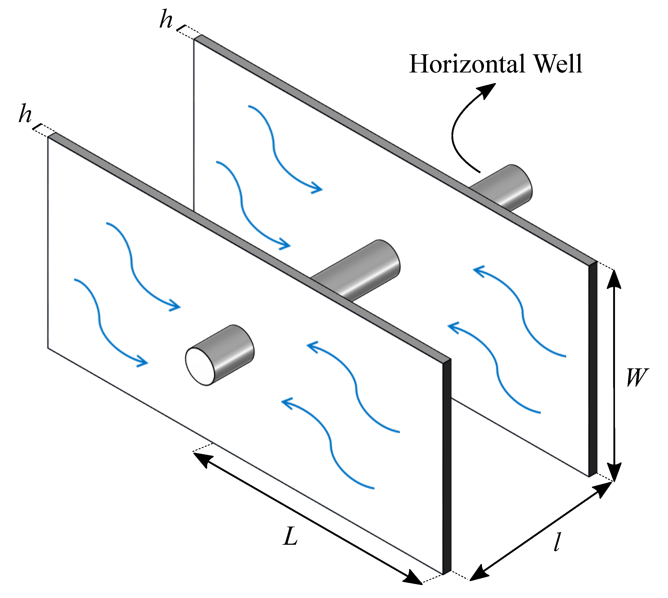
We consider the flow, devoid of temperature effects, of an incompressible fluid in a rectangular fracture of length L and width W along the x and y directions, respectively, see Figure 1. The fracture is the void space limited by two smooth elastic walls of time-dependent aperture h = h ( t ) along the z direction, and volume V ( t ) = h ( t ) LW . The aperture h ( t ) is much smaller than the other two fracture dimensions. The initial separation h 0 = h ( t = 0 ) results from the uniform pressure p e = p ( x , 0 ) imposed at the outlet, while the no-flow condition, the least impacting among boundary conditions, is considered at the other end ( x = L ). As the fluid flows out of the fracture at the origin, the pressure drops and the elastic walls relax, squeezing the fluid out of the fracture.
We hypothesize that a power-law constitutive law adequately reproduces the shear-thinning behavior of polymer fluids; expressing the relationship between shear stress and shear rate in terms of the apparent viscosity μ app as τ z x = μ app u ( z , t ) / z allows writing
μ a p p = m | u ( z , t ) z | 1 n 1
where m is the consistency index, n is the shear-thinning exponent, and u is the velocity in the x direction. The flow of an incompressible fluid between two parallel plates is governed by the momentum balance
z μ a p p u ( z , t ) z = p ( x , t ) x .
Substituting Equation (1) in Equation (2) and integrating leads to
m | u ( z , t ) z | 1 n 1 u ( z , t ) z = p ( x , t ) x z + c 1 ,
where c 1 is a constant of integration that is null due to the symmetry of the velocity profile with respect to the mid-plane of the fracture, u ( z , t ) / z ( 0 , t ) = 0 , that has been imposed as a boundary condition.
Subsequently, by imposing the Navier’s linear slip condition at both walls [29], i.e.,
u ( 0 , t ) = u ( h , t ) = s i g n u ( z , t ) x k ¯ u ( z , t ) z | z = 0 , h = k ¯ h ( t ) 2 m 1 n | p ( x , t ) x | 1 n 1 p ( x , t ) x
where k ¯ is the slip length (or friction coefficient) of dimensions [L], the velocity profile is further integrated to yield
u ( z , t ) = n 1 + n 1 2 n + 1 m 1 n h ( t ) 1 + n n | z h ( t ) | 1 + n n k ¯ h ( t ) 2 m 1 n | p ( x , t ) x | 1 n 1 p ( x , t ) x .
The mean velocity across the fracture is then
u ¯ ( t ) = n 2 n + 1 h ( t ) 1 + n 2 1 + n m 1 n + k ¯ h ( t ) 2 m 1 n | p ( x , t ) x | 1 n 1 p ( x , t ) x ,
and enforcing the continuity equation in the form
d h ( t ) d t + h ( t ) u ¯ ( t ) x = 0
yields upon substituting Equation (6) in Equation (7)
d h ( t ) d t = n 2 n + 1 h ( t ) 2 n + 1 2 1 + n m 1 n + k ¯ h ( t ) n + 1 2 m 1 n | p ( x , t ) x | 1 n 1 2 p ( x , t ) x 2 .
The backflow toward the inlet induces the relaxation of the walls due to a progressive pressure reduction across the fracture. The fracture flow rate per unit width is defined as q = ( 1 / W ) d V / d t = L d h / d t . In analogy to Winkler’s theory of linear foundations applied to the wall (for convenience the wall reaction is concentrated in the upper wall while in reality equally pertains to both walls), the walls’ reaction r ( t ) , a force per unit width, is proportional to the aperture, i.e., r ( t ) = E h ( t ) [26], where the coefficient of subgrade reaction E = E 0 / l depends on the Young modulus of the layer’s material, E 0 , and on the fracture spacing l (see Figure 2). This approach holds as long as l < L < 1 . Under this conceptualization, the equilibrium at the wall requires
0 L p ( x , t ) d x = r ( t ) L = E 0 h ( t ) L l ,
Simplifying the boundary conditions by neglecting the convergence of flow lines at the fracture outflow, the initial and boundary conditions to Equations (7) and (9) are: h ( 0 , t ) = h 0 is the initial fracture aperture, p ( 0 , t ) = p e is the pressure at the fracture outflow, and p ( x , t ) / x ( L , t ) = 0 , is the condition at the fracture inflow, the least impacting condition on the pressure within the fracture. The dimensionless formulation of the problem is
1 H ( T ) 2 n + 1 n d H ( T ) d T = 1 + 2 ( 2 n + 1 ) n N s H ( T ) | P ( X , T ) X | 1 n 1 2 P ( X , T ) X 2 ,
0 1 P ( X , T ) d X = H ( T ) P e ( X , T ) ,
in terms of the following dimensionless quantities,
X = x L , T = t t c , H = h h 0 , P = p p e E h 0 , P e = p e p c , N s = k ¯ h 0 ,
where N s is a slip number expressing the slip length in the dimensionless form [28] and the time and pressure scales t c and p c are
t c = ( 2 n + 1 ) m E 1 n 2 L h 0 n + 1 n , p c = E h 0 .
The initial and boundary conditions expressed in the dimensionless form are:
H ( X , 0 ) = 1 , P ( 0 , T ) = 0 , P ( X , T ) X ( 1 , T ) = 0 .

3. Solution

Solving the equations governing the problem requires the definition of an auxiliary function
G ( T ) = 1 [ n H ( T ) + 2 ( 1 + 2 n ) N s ] H ( T ) 1 + n n d H ( T ) d T
to integrate Equation (10) with boundary conditions given by the second and third expression in Equation (14), obtaining the pressure field as
P ( X , T ) = [ G ( T ) ] n n n ( n + 1 ) 1 ( 1 X ) n + 1 .
Then the final governing ordinary differential equation is derived by introducing Equations (15) and (16) into Equation (11)
d H ( T ) d T + n ( n + 2 ) 1 n H ( T ) + 2 2 n + 1 n N s H ( T ) n + 1 n [ H ( T ) P e ] 1 n = 0 ,
which needs to be integrated over time with the initial condition given by the first expression in Equation (14). Noteworthy, Equation (17) reduces to the following cases: (i) no-slip Newtonian flow [26] for n = 1 , N s = 0 ; (ii) no-slip power-law flow [27] for N s = 0 ; (iii) slip Newtonian flow [28] for n = 1 and N s 0 . The first two are amenable to an analytical solution, while the third requires a numerical approach, as does the present case.

4. Results

We commence our numerical investigation by solving the nonlinear governing ordinary differential equation (ODE) of Equation (17) subjected to the initial condition ( H ( X , 0 ) = 1 ) of Equation (14) using the ’ODE15s’ subroutine in Matlab [30]. The latter is a specialized numerical method designed for tackling stiff ODE systems through the utilization of numerical differentiation formulae. The efficiency of employing this numerical technique for solving nonlinear ODEs has been previously validated in our earlier research, particularly in the context of studying the one-dimensional drainage of power-law fluids from a finite-length fracture edge [31]. In our numerical studies, we adopt a dimensionless slip number of N s = k ¯ / h 0 0.01 which has been derived from experimental findings by Zheng et al. [32]. Their research reports h 0 = 500   μ m as the value of the initial fracture aperture and k ¯ = 8.84   μ m as the slip length. In what follows, we present the numerical results for various combinations of model parameters.

4.1. Time Evolution of Fracture Aperture

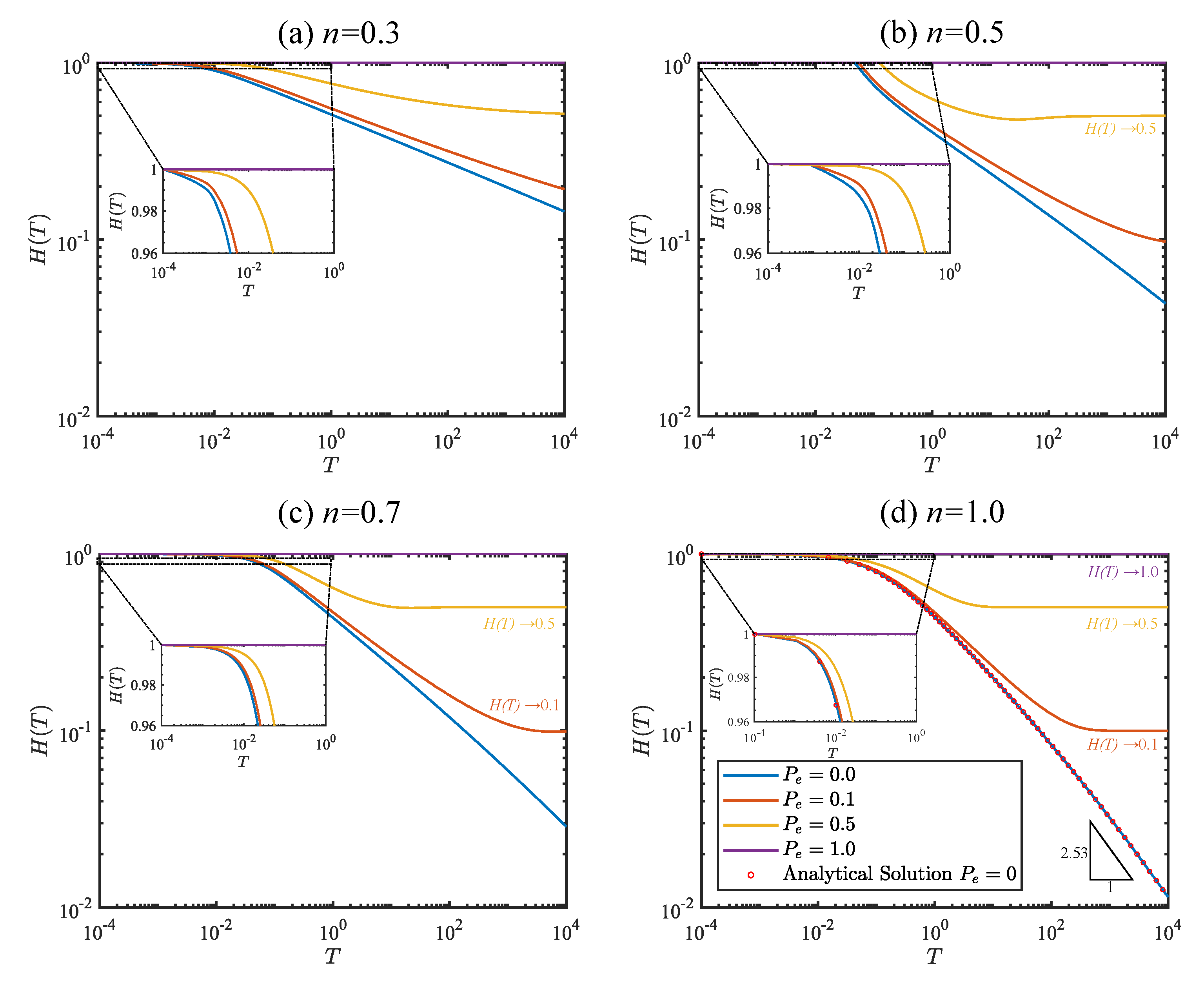
We investigate the backflow behavior of power-law fluids by examining the time evolution of fracture aperture, as illustrated in Figure 3. Our numerical analysis is primarily focused on two categories of fluids: Newtonian fluids (with n = 1 ) and shear-thinning fluids with varying fluid indices ( n = [ 0.3 , 0.5 , 0.7 ] ). These fluid types are commonly encountered in the context of fracturing fluids within geological fractures [33,34].
The results for different n values are depicted in Figure 3a–d on a log-log scale, spanning a dimensionless time range of T m i n = 10 4 to T m a x = 10 4 . The temporal resolution is set at Δ T = 0.001 , and the dimensionless fracture aperture H ( T ) spans between 0.01 and 1. For a Newtonian fluid (as depicted in Figure 3d), as time progresses, the numerical solution for H ( T ) gradually converges to zero with a negative slope of m = 1 / 2.53 when the external pressure is absent. Conversely, in scenarios where P e is non-zero, the late-time solutions exhibit an asymptotic behavior, stabilizing at a constant value equivalent to the external pore pressure, i.e., H ( T > > 1 ) P e . It is worth noting that in the absence of external pressure, the ODE of Equation (17) admits a semi-analytical solution, as documented in Ref. [28]. These semi-analytical results are superimposed on Figure 3d using red dots, revealing a good agreement with our numerical predictions.
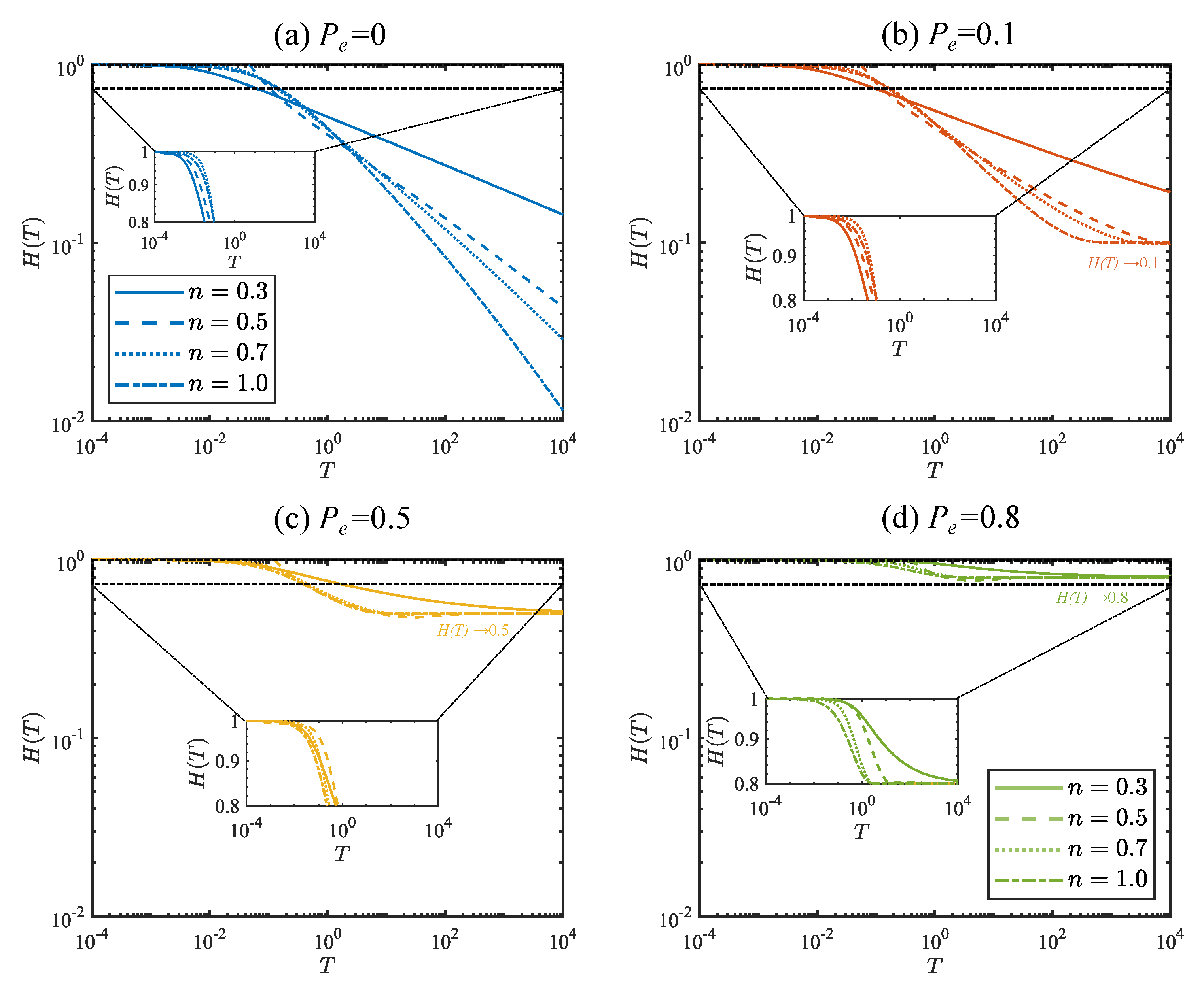
We observe that by modifying the fluid behavior index, the backflow propagation of shear-thinning fluids significantly changes. At early times ( T < < 1 ) , H ( T ) is approximately unit, and it decreases more rapidly for smaller n values, as depicted in the insets of Figure 3a–c. In contrast, for late-time solutions, H ( T ) reaches its asymptotic values for P e = 0.1 and P e = 0.5 more rapidly by increasing the n value, as shown in Figure 3a–c. In cases where P e = 0 , H ( T ) approaches zero at a swifter rate with a steeper slope for shear-thinning fluids featuring a smaller n index. We remark that across all these case studies, the value P e = 1 serves as a limit one for the borehole pressure.
Figure 4 demonstrates the same results for increasing external pressure values. In specific, Figure 4a depicts the results for P e = 0 with variable n values. It can be inferred from the figure that the slope of H ( T ) increases by increasing n , leading to an earlier closure of the fracture aperture. The shear-thinning behavior of the carrier fluid favors the tracer’s recovery by fastening the backflow to the inlet, as the apparent viscosity across the fracture’s cross-section reduces. When we increase the external pressure from 0.1 to 0.8 , the asymptotic constant value of the late-time solution is obtained earlier for shear-thinning fluids with larger n values (see Figure 4c,d). The higher the pressure gradients, the more the carrier fluid thins, resulting in a lower apparent viscosity. The early-time solutions visualize the rapid change of fluids with higher n values, as shown in the insets of Figure 4a–d.

4.2. Effect of the Friction Coefficient on the Fracture Opening

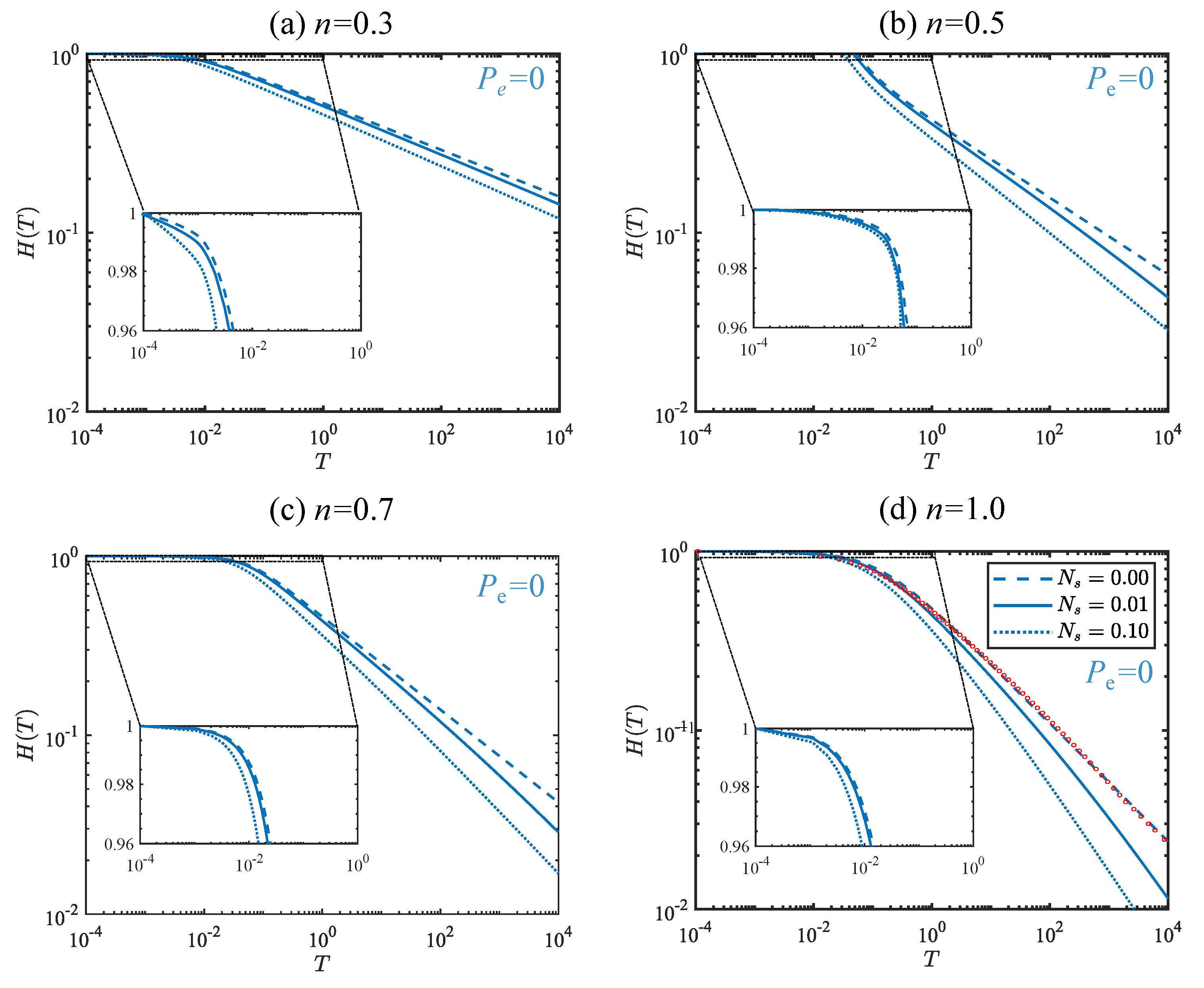
We aim to examine how the dimensionless slip number ( N s ), representing the friction coefficient of elastic walls, influences the backflow phenomenon in power-law fluids. To achieve this, we conduct a parametric analysis, specifically investigating the impact of slip length across three scenarios: N s = [ 0 , 0.01 , 0.1 ] . These values span two orders of magnitude, aligning with experimental data from Zheng et al. [32], broadening the previous analysis conducted for a single N s value.
We solve the nonlinear ODE presented in Equation (17) with zero external pressure ( P e = 0 ) and varying fluid behavior indices, specifically n = [ 0.3 , 0.5 , 0.7 , 1.0 ] , as depicted in Figure 5a–d, respectively. It can be concluded that by altering the slip length values, the fundamental characteristics of both shear-thinning and Newtonian flows are preserved. Across all scenarios, when there is no friction between the fluid and the elastic fracture walls, the fracture aperture approaches zero with a steeper slope. In contrast, when friction is introduced, the fracture remains open for a more extended duration of time. Furthermore, we observe that shear-thinning fluids reach H ( T ) = 0 more rapidly, particularly for lower n values. We should also remark that our numerical solution, in the absence of slip effects and with a Newtonian fluid, aligns with the analytical solution documented in Ref. [26], denoted by the red dots in Figure 5d.
In the next step of our numerical investigation, we replicate the same scenarios, but this time we consider a dimensionless external pressure ( P e = 0.1 ), as illustrated in Figure 6a–d. The key observation in this scenario is that the fundamental physical characteristics of early-stage backflow propagation within a finite-length elastic fracture remain unchanged when increasing the external pressure from P e = 0 to P e = 0.1 . This constancy is attributed to the dominant role of the carrier fluid in keeping the fracture aperture open during early times. On the contrary, the fracture aperture reaches the asymptotic value of H ( T ) P e in the late time solutions for the case of non-zero external pressure. Similar to the zero-pressure cases of Figure 5, shear-thinning fluids with lower fluid behavior indices reach zero more swiftly, while the introduction of friction prolongs the period during which the fracture remains open. The impact of the friction coefficient, however, is not significant in the early-time solutions, yet becomes more remarkable during the late-time stages of hydraulic fracturing likewise the case of zero external pressure.

4.3. Pressure Distribution Inside the Fracture

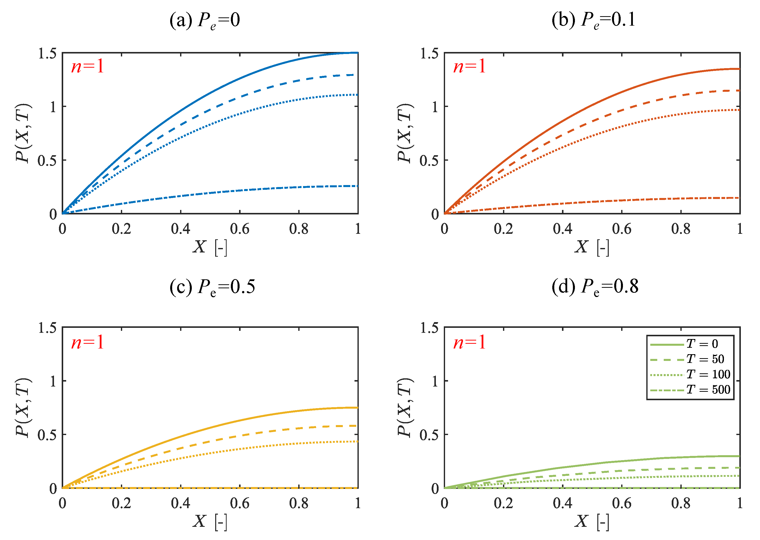
We additionally aim to comprehend the temporal progression of pressure within the fracture across its length along the x -axis. To achieve this, we numerically calculate the pressure field defined in Equation (16), by substituting the values of G ( T ) and H ( T ) acquired from Equations (15) and (17), respectively. These dimensionless pressure profiles are shown for distinct dimensionless time instances, T = [ 0 , 50 , 100 , 500 ] , corresponding to the early, middle, and late time instances.
The results are summarized in Figure 7a–d for a Newtonian fluid propagating along the dimensionless horizontal axis ( x ), which is normalized by the length of the fracture. These results correspond to various external pressure values, specifically P e = [ 0 , 0.1 , 0.5 , 0.8 ] . In all these case studies, the pressure profiles at the initial times are zero at the fracture outlet ( X = 0 ) and increase along the fracture length, reaching their maximum at the crack tip located at the fracture inlet ( X = 1 ). As time progresses, we observe a gradual flattening of the pressure profiles, accompanied by a reduction in pressure at the crack tip. For cases with P e 0.5 , the pressure field eventually becomes null at later time instances, specifically P ( X , T 500 ) = 0 , as demonstrated in Figure 7c,d. The results presented in Figure 7 lead to the conclusion that as the external pressure increases, the pressure fields within the fracture flatten and decrease. The most reduced pressure profiles are achieved when the external pressure is at its highest, as illustrated in Figure 7d. Conversely, the more significant internal pressure is observed when there is no external pressure, as for the case presented in Figure 7a.
We provide a similar analysis for a shear-thinning fluid with a power-law index of n = 0.3 , considering the influence of external pressure variation, as displayed in Figure 8a–d. Shear-thinning fluids demonstrate a pressure distribution within the fracture that resembles what we observed in the case of Newtonian fluids, albeit with somewhat larger magnitudes for all external pressure levels. The pressure initiates at zero at the fracture outlet ( X = 0 ) and progressively rises along the length of the fracture, reaching its peak values at the crack tip ( X = 1 ). In the late-time propagation of shear-thinning fluids, there is an almost constant value close to zero for P e 0.8 , as demonstrated in Figure 8d. We also observe that the pressure variation from the outlet to the inlet is more prominent when the external pressure is lower. The most significant variation is evident in the case where the external pressure is absent, as illustrated in Figure 8a. In all examined scenarios, the late-time pressure profile inside the fracture exhibits higher values for the shear-thinning fluid compared to the Newtonian fluid.
In our final endeavor, we focus on analyzing the impact of the slip number ( N s ) on pressure distribution within the fracture. Specifically, we examine scenarios with no slip at the elastic walls ( N s = 0 ) and a relatively large slip number ( N s = 0.1 ) for increasing dimensionless time instances of T = [ 0 , 50 , 100 , 500 ] . In both instances, we conduct our analysis using a shear-thinning fluid with n = 0.3 and a Newtonian fluid, as illustrated in Figure 9a,b, respectively. Our numerical investigation reveals that pressure profiles within the fracture exhibit limited sensitivity to the variations of the slip number for both shear-thinning and Newtonian fluids. Notably, the influence of the slip number becomes more prominent in the context of late-time pressure profiles. Consequently, the slip effect induced by the elastic walls of the fracture appears to be a relatively less influential factor in shaping the internal pressure field.

5. Conclusions

Hydraulic fracturing has gained significant attention in recent years due to its environmental implications, particularly with regard to the by-products and fluid wastewater generated during the extraction of hydrocarbons from fractured wells. This wastewater, often referred to as backflow, results from the relaxation of elastic fracture boundaries, which are pre-strained and subsequently balanced by the internal pressure of a viscous fluid.
In this study, we investigated the backflow of a power-law fluid within a two-dimensional flat-walled fracture having a finite length, characterized by a time-dependent aperture h ( t ) . This aperture possessed an initial and constant gap opening. The fracture was filled with an incompressible and viscous fluid. At the initial time instant, the fracture walls experienced a no-flow condition at the far end of the fracture while maintaining a constant initial pressure at the outlet. Upon releasing the pre-strained upper plate, fluid was expelled from the outlet, resulting in fluid pressure directed towards the outlet, described by a time-dependent pressure distribution inside the fracture. To formulate the problem we made the following assumptions:
  • We employed the lubrication approximation, assuming the fracture aperture is significantly smaller than its characteristic length.
  • We applied the linear Navier slip law to model the friction of the fracture walls.
  • We utilized the Winkler model of elastic foundations to represent the elastic deformation of the pre-strained fracture walls.
Under these assumptions, we numerically determined the time evolution of the fracture aperture by solving the governing ODE while considering different values of the model parameters via parametric analysis. The main conclusions of this work are:
  • Our numerical results recover the semi-analytical solutions of the special case of Newtonian fluid and zero external pressure.
  • When the external pressure is non-zero, the fracture aperture reaches the asymptotic value of H ( T ) P e in the late stages of hydraulic fracturing for both Newtonian and non-Newtonian fluids. The asymptotic value is obtained at early times for the shear-thinning fluids with larger n values.
  • The fluid rheological index ( n ) remarkably modifies the backflow propagation inside the fracture.
  • The variation of slip number ( N s ) does not have a significant impact on the overall physics of the problem.
In summary, our study contributes to the backflow analysis for power-law fluids, highlighting the fundamental role played by the fluid rheological model, friction coefficient, and external pressure. These insights are not only valuable for the field of hydraulic fracturing and subsurface heat recovery but also have broader applications in geology, civil, mechanical, petrochemical, and environmental engineering. The scope of this study can be expanded by exploring alternative slip laws, more complex fluid rheological models, including the Ellis model, and the effect of fluid compressibility. These additions offer valuable insights into how different boundary conditions and non-Newtonian fluid behavior affect fracture backflow dynamics, enriching our understanding of the topic.

Author Contributions

Conceptualization, A.L., F.Z. and V.D.F.; methodology, A.L., F.Z., I.D. and V.D.F. software, F.Z.; validation, A.L., I.D. and V.D.F.; formal analysis, A.L. and F.Z.; investigation, F.Z. and A.L.; writing—original draft preparation, A.L., F.Z. and V.D.F.; writing—review and editing, A.L., F.Z., I.D. and V.D.F.; visualization, F.Z.; supervision, V.D.F.; project administration, V.D.F.; funding acquisition, V.D.F. All authors have read and agreed to the published version of the manuscript.

Funding

This research received no external funding.

Data Availability Statement

The data presented in this study are available on request from the corresponding author.

Conflicts of Interest

The authors declare no conflict of interest.

Nomenclature

The following abbreviations are used in this manuscript:
k ¯ Slip length (friction coefficient) [L]
μ a p p Apparent viscosity of the carrier fluid [ M L 1 T n ]
τ z x Shear stress acting on the fracture wall [ M L 1 T 2 ]
E 0 Elastic modulus of the fracture walls [ M L 1 T 2 ]
h ( t ) Time dependent fracture aperture [L]
h 0 Initial fracture aperture at the initial time step ( t = 0 ) [L]
K s Dimensionless slip number [-]
L Fracture length [L]
l Fracture spacing [L]
m Power-law fluid consistency index [ M L 1 T n ]
n Power-law fluid index [-]
p ( x , t ) Pressure inside the fracture [ M L 1 T 2 ]
p e Uniform external pressure [ M L 1 T 2 ]
q Fracture flow rate [ L 3 T 1 ]
u ( x , z , t ) Fluid velocity [ L T 1 ]
W Fracture width [L]
tFracture flow propagation time [T]
EGSEnhanced Geothermal Systems
HDRHot Dry Rock
ODEOrdinary Differential Equation
STShear-thinning Fluid
TIBTThermal Injection Backflow Test

References

  1. van der Zwaan, B.; Longa, F.D. Integrated assessment projections for global geothermal energy use. Geothermics 2019, 82, 203–211. [Google Scholar] [CrossRef]
  2. Dalla Longa, F.; Nogueira, L.P.; Limberger, J.; van Wees, J.D.; van der Zwaan, B. Scenarios for geothermal energy deployment in Europe. Energy 2020, 206, 118060. [Google Scholar] [CrossRef]
  3. Gong, H.; Wang, B.; Liang, H.; Luo, Z.; Cao, Y. Strategic analysis of China’s geothermal energy industry. Front. Eng. Manag. 2020, 8, 390–401. [Google Scholar] [CrossRef]
  4. Tester, J.W.; Anderson, B.J.; Batchelor, A.S.; Blackwell, D.D.; DiPippo, R.; Drake, E.M.; Garnish, J.; Livesay, B.; Moore, M.C.; Nichols, K.; et al. Impact of enhanced geothermal systems on US energy supply in the twenty-first century. Philos. Trans. R. Soc. Math. Phys. Eng. Sci. 2007, 365, 1057–1094. [Google Scholar] [CrossRef]
  5. Olasolo, P.; Juárez, M.; Morales, M.; D’Amico, S.; Liarte, I. Enhanced geothermal systems (EGS): A review. Renew. Sustain. Energy Rev. 2016, 56, 133–144. [Google Scholar] [CrossRef]
  6. Alvarado, V.; Manrique, E. Enhanced Oil Recovery: An Update Review. Energies 2010, 3, 1529–1575. [Google Scholar] [CrossRef]
  7. Kakati, A.; Bera, A.; Al-Yaseri, A. A review on advanced nanoparticle-induced polymer flooding for enhanced oil recovery. Chem. Eng. Sci. 2022, 262, 117994. [Google Scholar] [CrossRef]
  8. McLennan, J.; Walton, I.; Moore, J.; Brinton, D.; Lund, J. Proppant backflow: Mechanical and flow considerations. Geothermics 2015, 57, 224–237. [Google Scholar] [CrossRef]
  9. Leung, D.Y.; Caramanna, G.; Maroto-Valer, M.M. An overview of current status of carbon dioxide capture and storage technologies. Renew. Sustain. Energy Rev. 2014, 39, 426–443. [Google Scholar] [CrossRef]
  10. Liu, J.W.; Wei, K.H.; Xu, S.W.; Cui, J.; Ma, J.; Xiao, X.L.; Xi, B.D.; He, X.S. Surfactant-enhanced remediation of oil-contaminated soil and groundwater: A review. Sci. Total Environ. 2021, 756, 144142. [Google Scholar] [CrossRef]
  11. Ellabban, O.; Abu-Rub, H.; Blaabjerg, F. Renewable energy resources: Current status, future prospects and their enabling technology. Renew. Sustain. Energy Rev. 2014, 39, 748–764. [Google Scholar] [CrossRef]
  12. Sanjuan, B.; Pinault, J.L.; Rose, P.; Gérard, A.; Brach, M.; Braibant, G.; Crouzet, C.; Foucher, J.C.; Gautier, A.; Touzelet, S. Tracer testing of the geothermal heat exchanger at Soultz-sous-Forêts (France) between 2000 and 2005. Geothermics 2006, 35, 622–653. [Google Scholar] [CrossRef]
  13. Kocabas, I. Geothermal reservoir characterization via thermal injection backflow and interwell tracer testing. Geothermics 2005, 34, 27–46. [Google Scholar] [CrossRef]
  14. Hermans, T.; Wildemeersch, S.; Jamin, P.; Orban, P.; Brouyère, S.; Dassargues, A.; Nguyen, F. Quantitative temperature monitoring of a heat tracing experiment using cross-borehole ERT. Geothermics 2015, 53, 14–26. [Google Scholar] [CrossRef]
  15. Jung, Y.; Pruess, K. A closed-form analytical solution for thermal single-well injection-withdrawal tests. Water Resour. Res. 2012, 48, 1–12. [Google Scholar] [CrossRef]
  16. Pruess, K. Enhanced geothermal systems (EGS) using CO2 as working fluid—A novel approach for generating renewable energy with simultaneous sequestration of carbon. Geothermics 2006, 35, 351–367. [Google Scholar] [CrossRef]
  17. Horne, R.N. Effects of Water Injection into Fractured Geothermal Reservoirs: A Summary of Experience Worldwide; Technical Report; Stanford Geothermal Program, Interdisciplinary Research in Engineering and Earth Sciences, Stanford University: Stanford, CA, USA, 1982. [Google Scholar] [CrossRef]
  18. Axelsson, G.; Flovenz, O.G.; Hauksdottir, S.; Hjartarson, A.; Liu, J. Analysis of tracer test data, and injection-induced cooling, in the Laugaland geothermal field, N-Iceland. Geothermics 2001, 30, 697–725. [Google Scholar] [CrossRef]
  19. Shi, Y.; Song, X.; Shen, Z.; Wang, G.; Li, X.; Zheng, R.; Geng, L.; Li, J.; Zhang, S. Numerical investigation on heat extraction performance of a CO2 enhanced geothermal system with multilateral wells. Energy 2018, 163, 38–51. [Google Scholar] [CrossRef]
  20. Cui, G.; Ren, S.; Dou, B.; Ning, F. Geothermal energy exploitation from depleted high-temperature gas reservoirs by recycling CO2: The superiority and existing problems. Geosci. Front. 2021, 12, 101078. [Google Scholar] [CrossRef]
  21. Lenci, A.; Putti, M.; Di Federico, V.; Méheust, Y. A Lubrication-Based Solver for Shear-Thinning Flow in Rough Fractures. Water Resour. Res. 2022, 58, e2021WR031760. [Google Scholar] [CrossRef]
  22. Lenci, A.; Méheust, Y.; Putti, M.; Di Federico, V. Monte Carlo Simulations of Shear-Thinning Flow in Geological Fractures. Water Resour. Res. 2022, 58, e2022WR032024. [Google Scholar] [CrossRef]
  23. Tosco, T.; Sethi, R. Transport of Non-Newtonian Suspensions of Highly Concentrated Micro- and Nanoscale Iron Particles in Porous Media: A Modeling Approach. Environ. Sci. Technol. 2010, 44, 9062–9068. [Google Scholar] [CrossRef]
  24. Comba, S.; Dalmazzo, D.; Santagata, E.; Sethi, R. Rheological characterization of xanthan suspensions of nanoscale iron for injection in porous media. J. Hazard. Mater. 2011, 185, 598–605. [Google Scholar] [CrossRef]
  25. Dejam, M. Dispersion in non-Newtonian fluid flows in a conduit with porous walls. Chem. Eng. Sci. 2018, 189, 296–310. [Google Scholar] [CrossRef]
  26. Dana, A.; Zheng, Z.; Peng, G.G.; Stone, H.A.; Huppert, H.E.; Ramon, G.Z. Dynamics of viscous backflow from a model fracture network. J. Fluid Mech. 2018, 836, 828–849. [Google Scholar] [CrossRef]
  27. Lenci, A.; Chiapponi, L.; Longo, S.; Di Federico, V. Experimental investigation on backflow of power-law fluids in planar fractures. Phys. Fluids 2021, 33, 083111. [Google Scholar] [CrossRef]
  28. Zeighami, F.; Lenci, A.; Longo, S.; Di Federico, V. Backflow Dynamics of Newtonian Fluids in an Elastic Fracture with Slip Walls. Environ. Sci. Proc. 2022, 20, 21045. [Google Scholar] [CrossRef]
  29. Ferrás, L.; Nóbrega, J.; Pinho, F. Analytical solutions for Newtonian and inelastic non-Newtonian flows with wall slip. J. Non-Newton. Fluid Mech. 2012, 175–176, 76–88. [Google Scholar] [CrossRef]
  30. MathWorks. MATLAB, version: 23.2.0.2391609 (R2023b); MathWorks: Portola Valley, CA, USA, 2023.
  31. Zeighami, F.; Lenci, A.; Di Federico, V. Drainage of power-law fluids from fractured or porous finite domains. J. Non-Newton. Fluid Mech. 2022, 305, 104832. [Google Scholar] [CrossRef]
  32. Zheng, L.; Wang, L.; Wang, T.; Singh, K.; Wang, Z.L.; Chen, X. Can homogeneous slip boundary condition affect effective dispersion in single fractures with Poiseuille flow? J. Hydrol. 2020, 581, 124385. [Google Scholar] [CrossRef]
  33. Zhong, L.; Oostrom, M.; Truex, M.; Vermeul, V.; Szecsody, J. Rheological behavior of xanthan gum solution related to shear thinning fluid delivery for subsurface remediation. J. Hazard. Mater. 2013, 244–245, 160–170. [Google Scholar] [CrossRef] [PubMed]
  34. Barbati, A.C.; Desroches, J.; Robisson, A.; McKinley, G.H. Complex Fluids and Hydraulic Fracturing. Annu. Rev. Chem. Biomol. 2016, 7, 415–453. [Google Scholar] [CrossRef] [PubMed]
Figure 1. The (a) 3D and (b) 2D schematics of a fracture with a finite length of L and a uniform aperture of h 0 varying over time and elastic wall behaving as an elastic foundation.
Energies 16 07999 g001
Figure 2. The three-dimensional schematics of wing symmetric fractures with spacing l . The arrows in the figure indicate the fluid flow direction.
Energies 16 07999 g002
Figure 3. Time evolution of fracture aperture for N s = 0.01 and different values of P e . Figures (ad) depict the results for different rheological index values. Red dots superimposed to (d) highlight the analytical solution for the specific case of n = 1 and P e = 0 adopted from Ref. [28].
Energies 16 07999 g003
Figure 4. Time evolution of fracture aperture for N s = 0.01 and different power-law fluid indeces n . Figures (ad) depict the results for different P e values. The continuous, dashed, dotted, and dashed-dot lines in the subfigures represent different rheological indices of power-law fluid: n = [ 0.3 , 0.5 , 0.7 , 1.0 ] , respectively.
Energies 16 07999 g004
Figure 5. Time evolution of fracture aperture for zero borehole pressure ( P e = 0 ) considering different flow behavior index in (ad) and different slip numbers ( N s variable). Again, red dots superimposed to (d) highlight the analytical solution for n = 1 and P e = 0 , see [28].
Energies 16 07999 g005
Figure 6. Time evolution of fracture aperture for a given borehole pressure ( P e = 0.1 ) considering different flow behavior indices in (ad) and different slip numbers ( N s variable).
Energies 16 07999 g006
Figure 7. The evolution of the dimensionless pressure distribution inside the fracture of Newtonian fluid ( n = 1 ) over time having different external pressures ( P e variable). The subfigures utilize solid, dashed, dotted, and dashed-dot lines to represent different time intervals: T = [ 0 , 50 , 100 , 500 ] , respectively.
Energies 16 07999 g007
Figure 8. The evolution of the dimensionless pressure distribution inside the fracture of a shear thinning fluid ( n = 0.3 ) over time having different external pressures ( P e variable). The subfigures utilize solid, dashed, dotted, and dashed-dot lines to represent different time intervals: T = [ 0 , 50 , 100 , 500 ] , respectively.
Energies 16 07999 g008
Figure 9. The evolution of the dimensionless pressure distribution inside the fracture of a (a) shear thinning fluid ( n = 0.3 ) and (b) Newtonian fluid ( n = 1 ) over time without ( N s = 0 ) and with slip effect on the fracture walls ( N s = 0.1 ). The subfigures utilize solid, dashed, dotted, and dashed-dot lines to represent different time intervals: T = [ 0 , 50 , 100 , 500 ] , respectively. The arrows in the subfigures denote the progression of time instances.
Energies 16 07999 g009
Disclaimer/Publisher’s Note: The statements, opinions and data contained in all publications are solely those of the individual author(s) and contributor(s) and not of MDPI and/or the editor(s). MDPI and/or the editor(s) disclaim responsibility for any injury to people or property resulting from any ideas, methods, instructions or products referred to in the content.