Article

Electromagnetic Vibration Analysis of Transverse Flux Permanent Magnet Linear Submersible Motor for Oil Production

1
College of New Energy, Harbin Institute of Technology (Weihai), Weihai 264209, China
2
School of Ocean Engineering, Harbin Institute of Technology (Weihai), Weihai 264209, China
3
Testing Technique Research Institute, Yichang 443000, China
*
Author to whom correspondence should be addressed.
Energies 2023, 16(23), 7911; https://doi.org/10.3390/en16237911
Submission received: 27 September 2023 / Revised: 6 November 2023 / Accepted: 1 December 2023 / Published: 4 December 2023

Abstract

:
A transverse flux linear motor is a special type of linear motor with a high thrust force density, and it has broad application prospects in the field of linear direct-drive systems. In the process of oil production, the vibration of the linear motor poses a significant amount of harm to the system due to its special slender structure. This paper focuses on the electromagnetic vibration of a transverse flux permanent magnet linear submersible motor (TFPMLSM). Firstly, the no-load air gap flux density is calculated based on the field modulation principle. Secondly, the radial electromagnetic force (REF) of the TFPMLSM is calculated, and the finite element method (FEM) is used to analyze the time-space and spectral characteristics of the REF. Then, the influence of secondary eccentricity on the frequency spectrum of the REF is further concluded. Finally, the natural frequencies of each vibration mode are calculated using the modal superposition method and the influence of the REF on the motor vibration is obtained through magnetic-structural coupling analysis. The research results found that the motor does not cause resonance at low speeds, and the fundamental frequency of REF has the greatest impact on electromagnetic vibration.

1. Introduction

Linear motors are used in applications as varied as robotics [1,2], electrical power generation [3,4], electromagnetic launchers [5,6,7] and transportation [8]. Linear motor-drive systems can directly provide linear reciprocating force without mechanical gears and rotary-to-linear conversion systems, which results in better dynamic performance, higher efficiency and reliability.
Many different types of linear permanent magnet machines have been studied to achieve a high thrust force. A transverse flux permanent magnet linear submersible motor (TFPMLSM) is a kind of motor with a high thrust force density [9,10,11] and it is expected to be applied to oil exploitation. In the process of oil production, the submersible linear motor will produce a lot of vibrations when it works underground for a long time, resulting in the failure of the submersible electric pump system, motor damage and other problems [12].
The electromagnetic vibration is one of the main sources of motor vibration. Many previous researchers have studied the main causes of the electromagnetic vibration of permanent magnet (PM) motors. The electromagnetic force was directly applied to a finite element (FE) model of stator core as an excitation force [13,14]. This research revealed that the main cause of electromagnetic vibration in PM synchronous motors is neither torque ripple nor cogging torque but an electromagnetic force acting in a radial direction known as the radial electromagnetic force (REF). However, the above studies were based only on a two-dimensional (2-D) finite element method (FEM), thereby limiting the accuracy and specific details of vibration characteristics.
The three-dimensional (3-D) FEM with high precision had been used to allow for a more accurate analysis of motor vibration. Ref. [15] proposed a 3-D entire FE model to analyze the vibration characteristics of a brushless direct current motor for more accurate results. Ref. [16] calculated the REF and vibration responses of permanent magnet-assisted synchronous reluctance machines (PM-SynRMs) by establishing the combined 2-D electromagnetic model and 3-D structural model. This research found that the rotor slot harmonic will produce extra REF which may cause serious vibration. The REF of switched reluctance motor was studied in [17] by 3-D FEM to reveal the motor vibration characteristics and reduce noise. The research found that the amplitude of noise and vibration will be inversely proportional to the slope of the decreasing REF.
The detailed electromagnetic vibration characteristics of motors have been studied by using the developed multi-physics model method combining various analytical and numerical methods. The magnetic field and radial force density of a PM brush dc motor were analyzed by using an analytical method and FEM to reveal the electromagnetic vibration characteristics [18,19]. A multi-physics model to predict the vibration and noise of a claw pole alternator is established in [20], the REF calculated by 3-D FEM is transferred to the structural meshing using the mapping method and the vibration and noise are calculated by using the modal superposition method (MSM) and boundary-element method (BEM). Ref. [21] studied the effect of a pole-slot match on the vibration of PM synchronous motors by using the electromagnetic field FEM and Maxwell stress tensor method. In order to evaluate the effect of REF on the vibration, the equivalent magnetizing current method was used in this study to calculate the local force.
Existing researchers mainly focused on the vibration of rotating motors, but only a few papers were related to the vibration of transverse flux linear motors. The previous study of transverse flux linear motors mainly focused on the electromagnetic and structure optimization design [22,23,24,25], while there was seldom any study on the electromagnetic vibration of TFPMLSM. Moreover, the above-mentioned studies did not consider the impact of rotor eccentricity fault on motor vibration characteristics. Considering the special slender structure and special working environment of a TFPMLSM, the mover is more likely to experience eccentricity and the vibration is more severe than other types of motors. Therefore, it is worth studying the electromagnetic force and vibration characteristics of TFPMLSMs.
In this paper, the no-load air gap flux density is firstly calculated based on the field modulation principle. Then, the REF is calculated using the Maxwell stress tensor method, and FEM is used to analyze the time-space and spectral characteristics of REF. The influence of secondary eccentricity on electromagnetic force is further simulated. Finally, the stator modes and electromagnetic vibration characteristics of TFPMLSM are analyzed and summarized.

2. The Structure and Operating Principle of TFPMLSM

2.1. Structure of TFPMLSM

2.1.1. Primary Structure

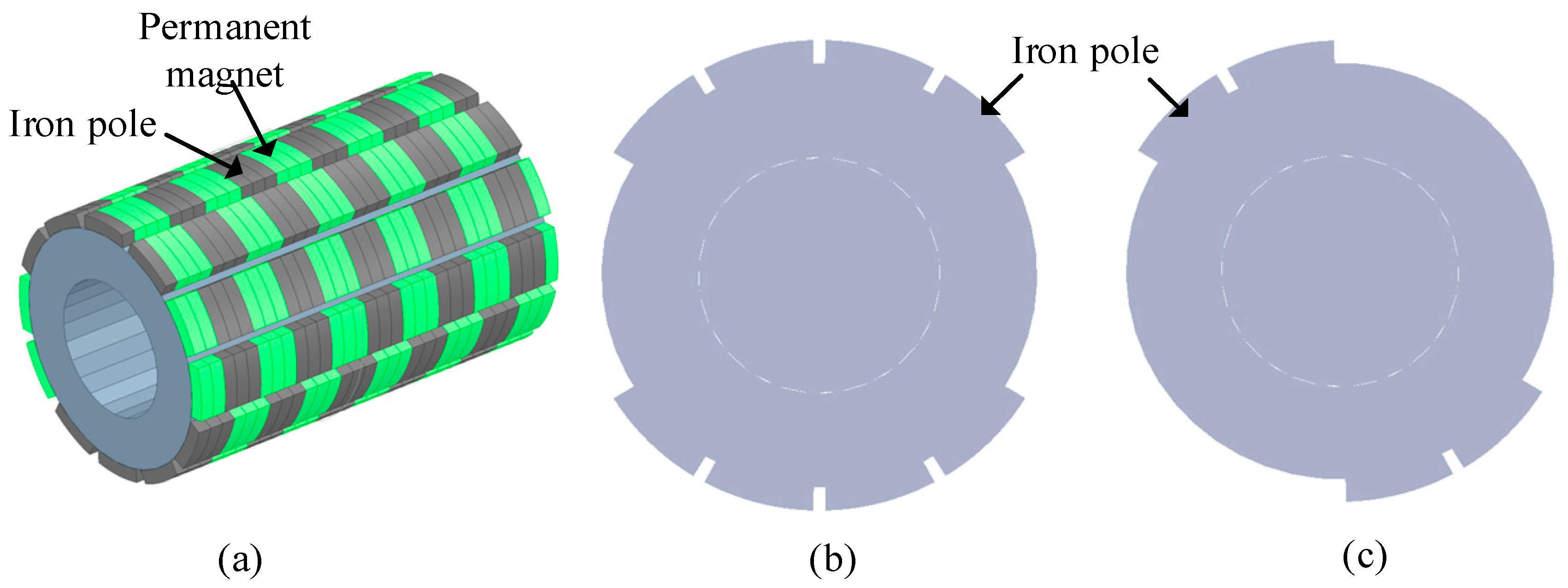
The primary of TFPMLSM serves as the stator, as shown in Figure 1a. The primary unit consists of an iron core, permanent magnets (PMs) and coils. The iron core is slotted along the axial direction and the three-phase centralized winding which adopts a Y-shaped connection is symmetrically distributed along the circumferential direction. The stator core adopts a 12 salient pole-teeth structure to offset the unilateral magnetic pull force of each phase, as shown in Figure 1b,c. Each lamination consists of six short teeth and six long teeth, and laminations A and B are alternately laminated along the axial direction. The radially magnetized PMs are attached to the surface of the short teeth and distributed alternately along the axial direction, which can reduce thrust fluctuations and improve the reliability of the TFPMLSM.

2.1.2. Secondary Structure

The secondary of the TFPMLSM, which serves as the mover, consists of a cylinder shaft, PMs and secondary iron core, as shown in Figure 2, where τ represents the pole distance. The secondary iron core can be formed by stacking two types of laminations in Figure 2b,c along the axial direction. After laminations C and D are sequentially stacked for a length of τ/3, they are rotated by 60° and sequentially stacked for another length of τ/3. Then, the two laminations are rotated by 60°and stacked again to form the secondary iron core by following this rule.
The vacant position on the secondary iron core is embedded with PMs to strengthen the main magnetic flux, and the iron poles on the secondary unit are used to form a magnetic circuit with the stator PMs. The axial length of the mover PM, which is the same as that of mover iron pole, is defined as the pole distance τ, as shown in Figure 2a.
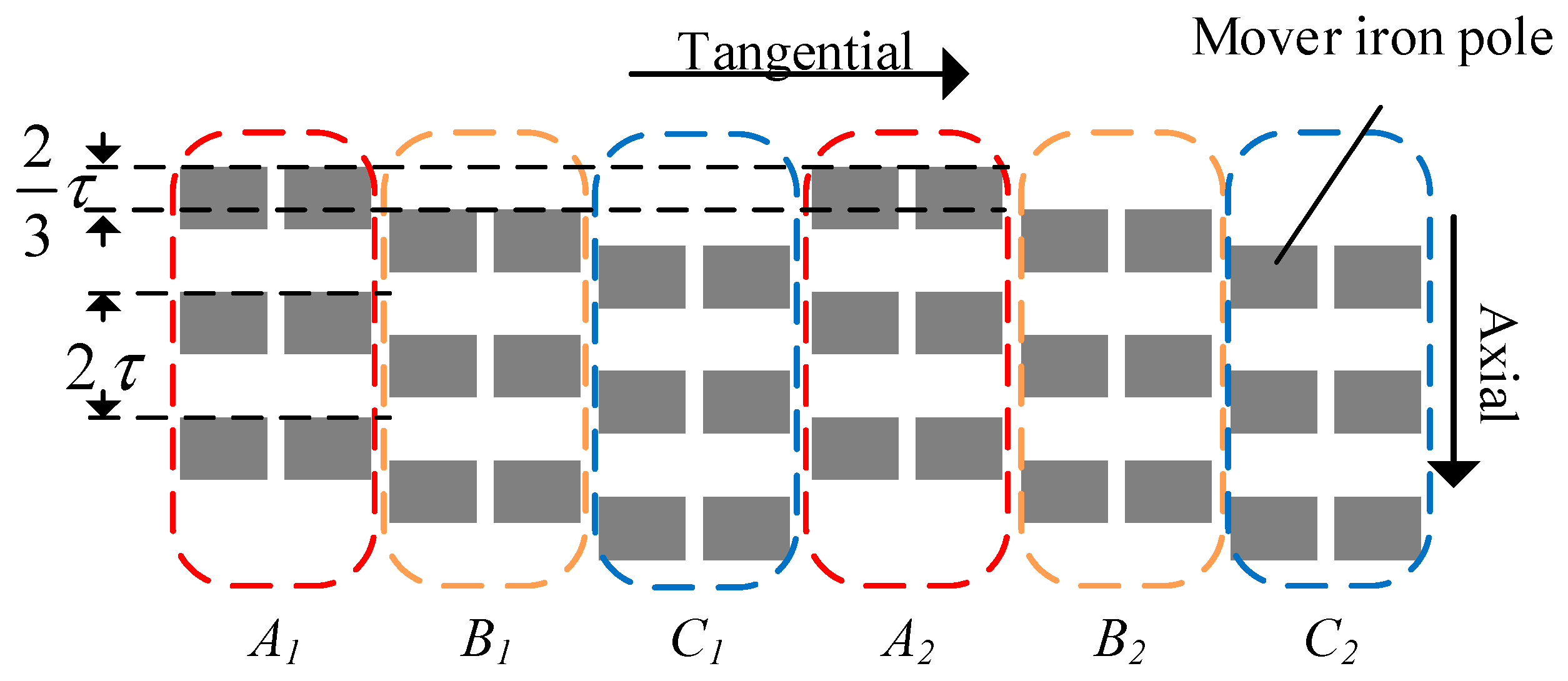
The alternating arrangement of iron poles and PMs in the axial direction forms a group of movers. The three groups of mover iron poles are staggered along the axial direction with length 2τ/3 to form a three-phase structure corresponding to the stator three-phase, as shown in Figure 3. The overall distribution of the mover iron poles in the circumferential direction is symmetrical, which can effectively reduce the cogging force.

2.1.3. Structure of Unit Motor

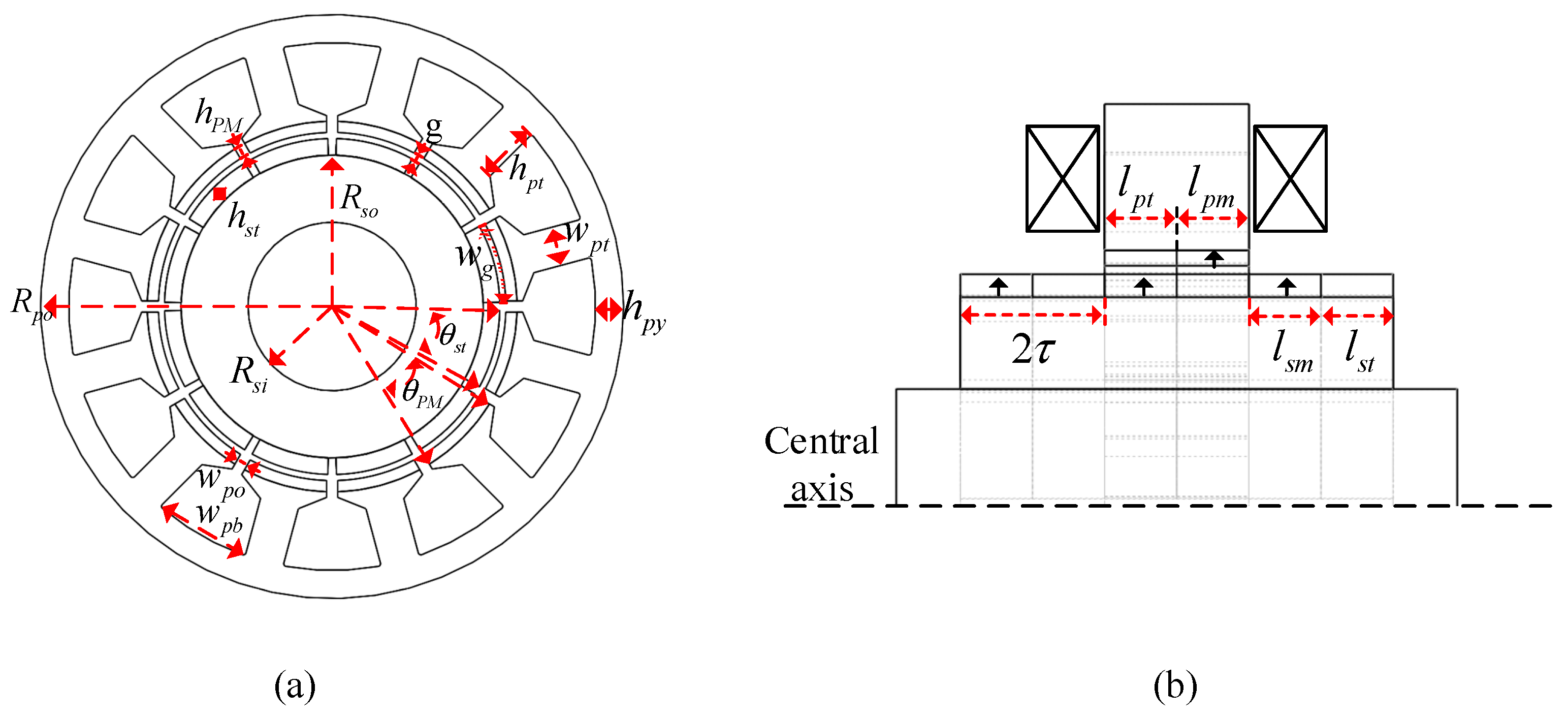
The 3-D model of the TFPMLSM studied in this paper is shown in Figure 4. Both stator and mover adopt the dual consequent pole structure, and the sandwiched iron poles are magnetized with opposite polarity by the adjacent PMs. The values and marks of the structural parameters of the TFPMLSM are shown in Table 1 and Figure 5, respectively.

2.2. Working Principle of TFPMLSM

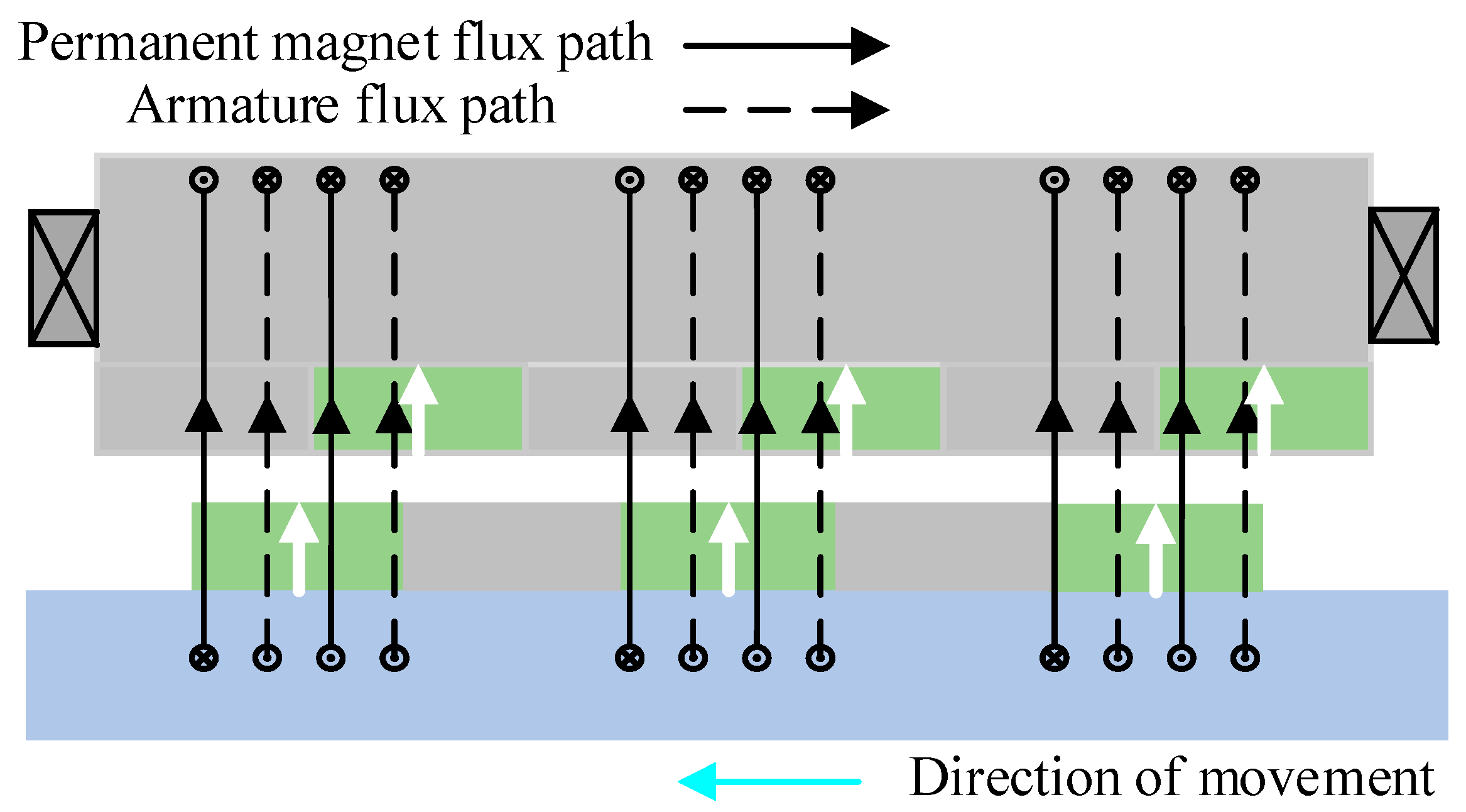
A TFPMLSM is a kind of variable reluctance motor and Figure 6 presents its axial flux path. The iron poles between the PMs have the ability to modulate the flux path. When the direction of the armature flux path is the same as the PM flux path, the upward flux is strengthened and according to the minimum reluctance principle, the mover will move forward under the action of electromagnetic force to provide the least reluctance path. The PM flux will reach maximum value in a positive direction when the stator PMs and mover iron poles are completely aligned, as shown in Figure 7a. By changing the direction of the current in the winding, the armature flux is in the opposite direction of the PM flux and the mover continues to be pulled forward by electromagnetic force until the PM flux reaches its maximum value in a negative direction, as shown in Figure 7b. The secondary will move continuously by applying an alternating current to the winding.

3. Analysis of Radial Electromagnetic Force

Compared to numerical methods, analytical methods can save much computational time. What is more, due to the fac that the REF is generated by the action of the air gap magnetic field on the stator, calculating the air gap flux density by an analytical method is the key to studying the electromagnetic characteristics of the TFPMLSM.

3.1. No-Load Air Gap Flux Density

In recent years, a new type of permanent magnet synchronous motor with high torque density and low torque ripple based on the principle of field modulation has received widespread attention. Many scholars have proposed various novel topologies and methods for magnetic field analysis [26,27] and improvement of power factor [28], which gradually developed a relatively complete field modulation theory.
The principle of field modulation is also applicable to transverse flux motors and it is adopted to calculate the air gap flux density of TFPMLSM, which can directly analyze the harmonic composition of the air gap flux density and reveal the influence of structural parameters on the motor magnetic field. The following assumptions are made to simplify the calculation:
  • The core saturation is ignored;
  • The eddy current losses and hysteresis losses are excluded;
  • Magnetic field only changes in the radial direction.
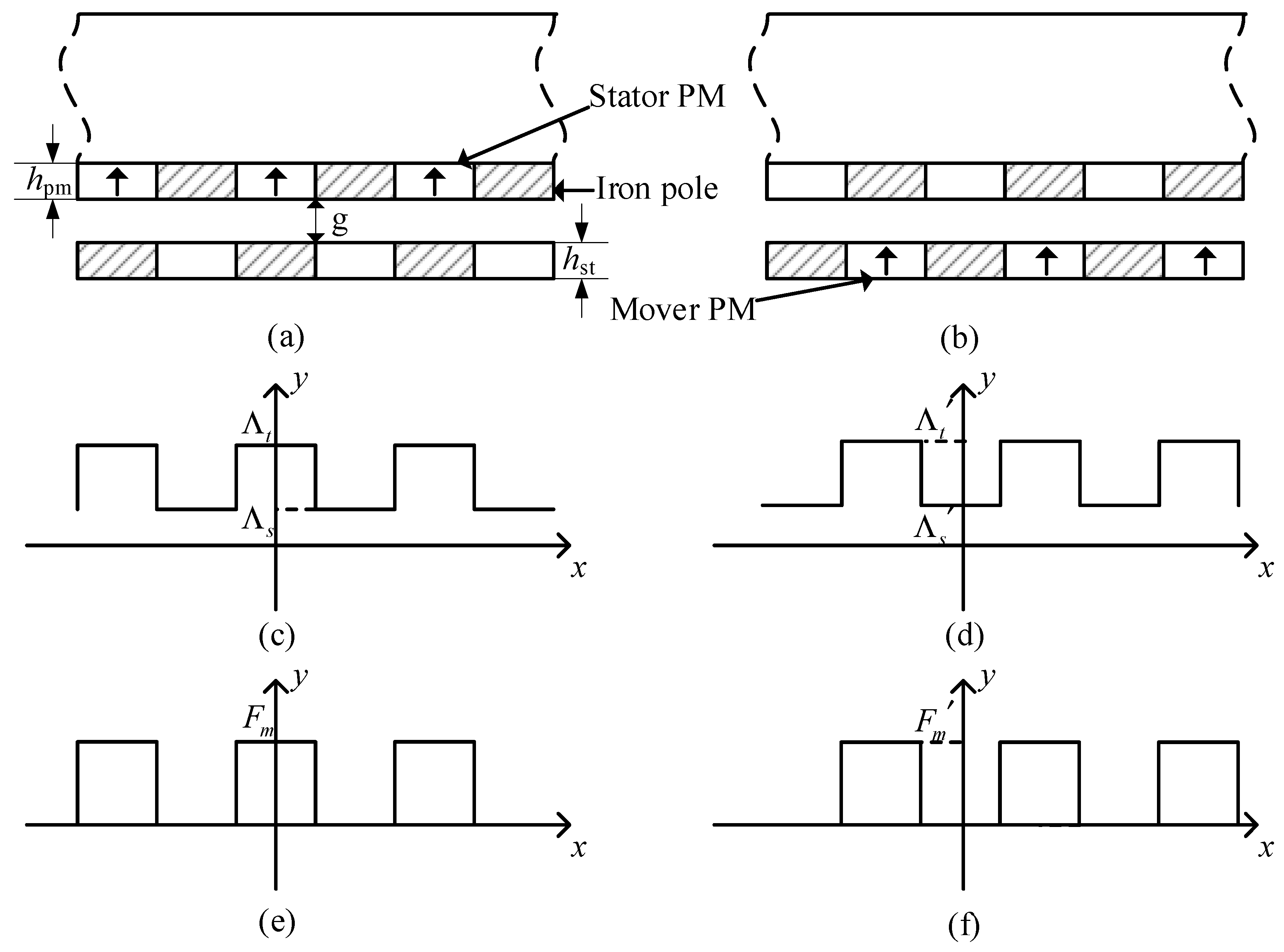
Due to the consequent pole structure of the stator and mover, the TFPMLSM can be decomposed into two sets of models for air gap flux density calculation: stator PMs and mover iron poles, and mover PMs and stator iron poles. The overall air gap flux density can be obtained by superposing the air gap flux density of two models. Figure 6 shows the PM magneto motive force (MMF) and iron pole permeance distribution of stator and mover.
In Figure 8, Λt represents the permeance per unit area of the mover iron pole:
Λ t = 1 h PM + g
The permeance per unit area between the iron poles can be expressed as:
Λ s = 1 h PM + g + h st
The Fourier series form of the permeance waveform shown in Figure 8c is:
Λ ( x , t ) = Λ 0 + i = 1 Λ i cos [ π i τ ( x v t ) ] Λ 0 = μ 0 τ ( Λ t l st + Λ s l sp ) = μ 0 ( 1 h pm + g + 1 h pm + g + h st ) Λ i = 2 μ 0 i π ( Λ t Λ s ) sin ( i π l st 2 τ ) = 2 μ 0 i π ( 1 h pm + g 1 h pm + δ + h st ) sin ( i π 2 )
where Λ0 is the DC component in the mover permeance, Λi is the harmonic coefficient of each order of mover permeance and v is the moving speed of mover.
Similarly, the Fourier series form of the MMF of stator PMs shown in Figure 8e is:
F pm ( x ) = F 0 + i = 1 F i cos ( π i τ x ) F 0 = F m l pm T = B r h pm 2 μ 0 F i = 2 T 0 T f ( x ) cos ( 2 π i x T ) d x = B r h pm i π μ 0 sin ( i π 2 )
where F0 is the DC component in the MMF of stator PMs. Fi is the harmonic coefficient MMF of stator PMs.
The MMF waveform of mover PMs and permeance waveform of stator iron poles are exactly 180° different from the MMF of stator PMs and permeance of mover iron poles. Therefore, the MMF of mover PMs can be expressed as:
F sm ( x , t ) = F 0 + i = 1 F i cos [ π τ ( x v t ) ] F 0 = F m l sm T = B r h st 2 μ 0 F i = 2 T 0 T f ( x ) cos ( 2 π i x T ) d x = B r h st i π μ 0 sin ( i π 2 )
where F0′ is the DC component in the MMF of mover PMs. Fi′ is the harmonic coefficient of MMF of mover PMs.
Similarly, the stator permeance can be expressed as:
Λ ( x ) = Λ 0 i = 1 Λ i cos ( π i τ x ) Λ 0 = μ 0 ( 1 h st + g + 1 h pm + g + h st ) Λ i = 2 μ 0 i π ( Λ t Λ s ) sin ( i π l pt 2 τ ) = 2 μ 0 i π ( 1 h st + g 1 h pm + g + h st ) sin ( i π 2 )
where Λ0′ is the DC component in the stator permeance. Λi′ is the harmonic coefficient of each order of stator permeance.
The expression of the air gap flux density at no-load by ignoring the influence of higher-order harmonics can be obtained as:
B g ( x , t ) = F pm ( x ) Λ ( x , t ) + F sm ( x , t ) Λ ( x ) = F 0 Λ 0 + F 0 Λ 0 + ( F 1 Λ 0 F 0 Λ 1 ) cos π x τ + ( F 0 Λ 1 F 1 Λ 0 ) cos π τ ( x v t ) + ( F 1 Λ 1 + F 1 Λ 1 ) cos π x τ cos π τ ( x v t )

3.2. Mathematical Analysis of Radial Electromagnetic Force

The REF which is the result of the air gap magnetic field acting on the stator core is the main factor causing electromagnetic vibration. The air gap magnetic field is generated by the interaction of the permanent magnet MMF, armature MMF and iron core permeance. The synthetic air gap flux density expression of the TFPMLSM is given by the following equation:
B g ( x , t ) = F pm ( x ) Λ ( x , t ) + F sm ( x , t ) Λ ( x ) + F w ( x ) [ Λ ( x , t ) + Λ ( x ) ]
where Fw(x) is the armature MMF.
The mover is the moving part and the mathematical expression of mover MMF is a function of position (x) and time (t).
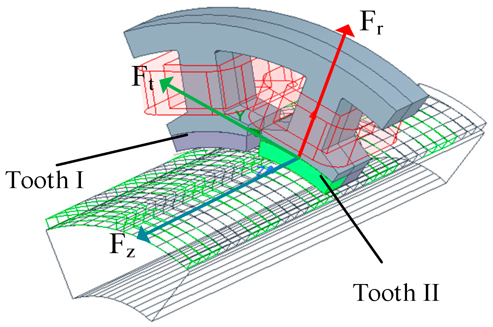
The electromagnetic force acting on the stator teeth is shown in Figure 9. According to the Maxwell stress tensor method, the mathematical expressions of the REF at three directions are as follows:
The radial electromagnetic force (REF) is:
F r ( x , t ) = 1 2 μ 0 [ b r 2 ( x , t ) b t 2 ( x , t ) b z 2 ( x , t ) ]
The tangential electromagnetic force is:
F t ( x , t ) = 1 μ 0 b r ( x , t ) b t ( x , t )
The axial electromagnetic force is:
F z ( x , t ) = 1 μ 0 b t ( x , t ) b z ( x , t )
where br(x,t), bt(x,t) and bz(x,t) are the radial, tangential and axial magnetic density components of the air gap flux density, respectively.
The mover moving direction of a traditional longitudinal flux motor is coplanar with the main flux and the axial air gap flux density is 0, as there is no axial movement of the mover. Ignoring tangential magnetic density, the radial electromagnetic force can be simplified as
F r ( x , t ) = 1 2 μ 0 b r 2 ( x , t )
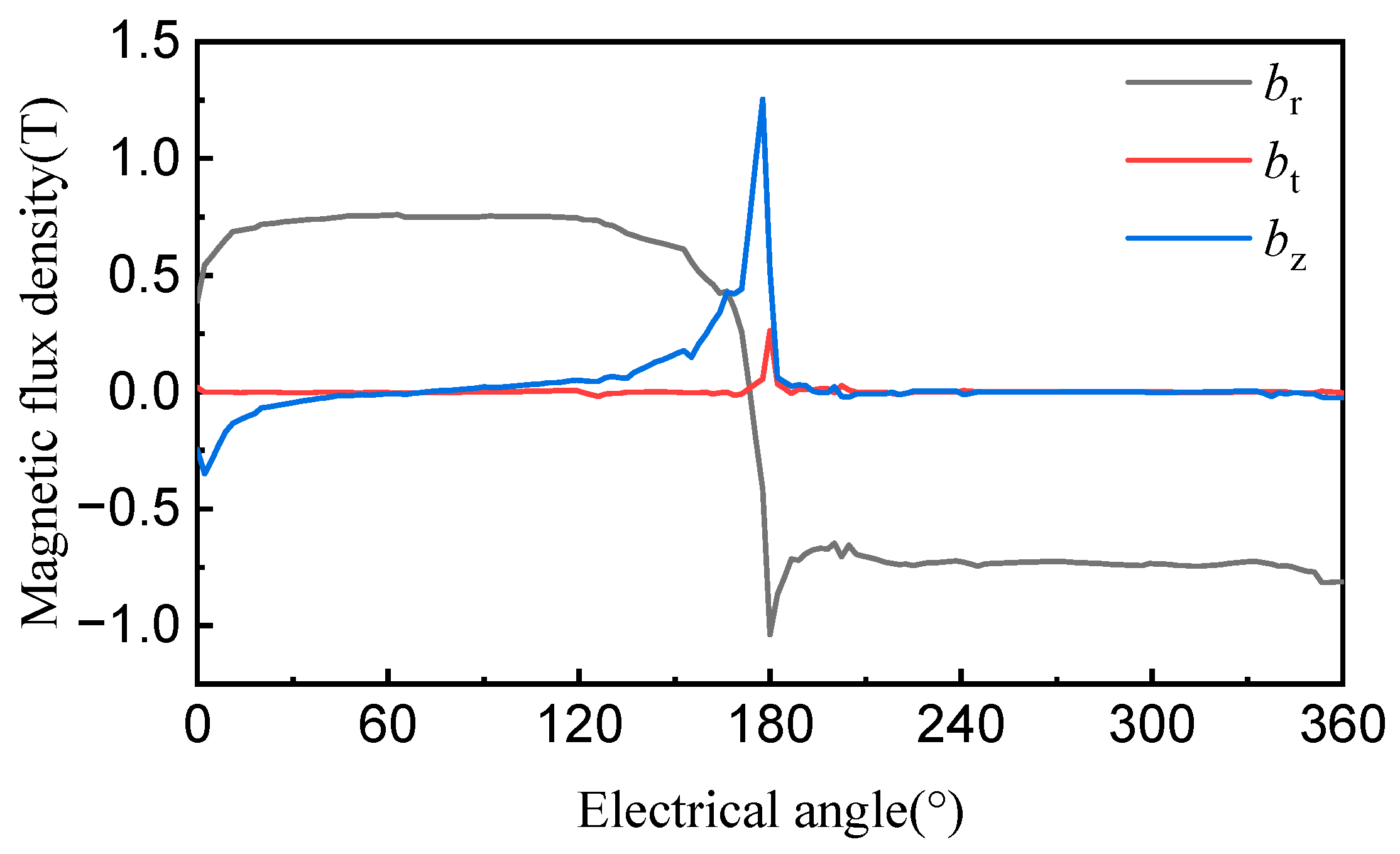
It can be seen that the REF of a traditional longitudinal flux motor is only related to the radial air gap flux density, while in contrast, transverse flux linear motors have axial flux density components that cannot be ignored. Figure 10 shows the distribution of air gap flux density under stator tooth II. It can be seen that the br is a relatively rectangular wave while the bt is small and can be ignored. For bz, a large amplitude appears at 180° and the axial component of the air gap flux density is non-ignorable. The simplified mathematical expression for radial electromagnetic force is:
F r ( x , t ) = 1 2 μ 0 [ b r 2 ( x , t ) b z 2 ( x , t ) ]
According to the linear superposition principle, the air gap flux density can be divided into armature flux density, stator PMs flux density and mover PMs flux density by ignoring the influence of winding current harmonics:
b r ( x , t ) = b wr _ i ( θ , t ) + b pr _ j ( x , t ) + b sr _ k ( x , t ) b z ( x , t ) = b wz _ i ( θ , t ) + b pz _ j ( x , t ) + b sz _ k ( x , t )
  • The armature flux density generated by the armature winding. The radial and axial flux density of the armature can be expressed as:
b wr _ i ( θ , t ) = i B wr _ i cos ( i p θ 2 π f t + ) b wz _ i ( θ , t ) = i B wz _ i sin ( i p θ 2 π f t + )
where Bwr_i and Bwz_i represent the ith harmonic amplitude of the radial and axial air gap flux density of the armature, respectively. p is pole pairs and f is current fundamental frequency.
2.
The flux density generated by the interaction between the stator PMs and the mover iron poles. The radial and axial air gap flux density of stator PMs can be expressed as:
b pr _ j ( x , t ) = j B pr _ j sin ( j p x 2 j τ f t + ) b pz _ j ( x , t ) = j B pz _ j cos ( j p x 2 j τ f t + )
where Bpr_j and Bpz_j represent the jth harmonic amplitude of the radial and axial air gap flux density of the stator PMs, respectively.
3.
The flux density generated by the interaction between the mover PMs and the stator iron poles. The radial and axial air gap flux density of mover PMs can be expressed as:
b sr _ k ( x , t ) = k B sr _ k cos ( k p x 2 k τ f t + ) b sz _ k ( x , t ) = k B sz _ k sin ( k p x 2 k τ f t + )
where Bsr_k and Bsz_k represent the kth harmonic amplitude of the radial and axial air gap flux density of the mover PMs, respectively.
The armature flux density is generated by the coil in the circumferential direction of the stator and is a function of θ. The flux density generated by PMs is related to the mover moving direction and is a function of the axial motion distance x. The simplified mathematical expression for REF is:
F r = B 0 + i B w cos ( 2 i p θ 4 π f t ) + j B ps sin ( 2 j p x 4 j τ f t + ) + i j B ws sin i p θ ± j p x 2 ( π ± j τ ) f t + + i j B wp cos i p θ ± j p x 2 ( π ± j τ ) f t +
where p is the pole pairs and f is the fundamental frequency. The first term B0 is the sum of the DC components generated jointly by the winding and PMs. The second and third items are harmonics generated by the winding acting separately with the stator PMs and mover PMs. The fourth item is the harmonic generated by the joint action of the winding with the mover PMs and the fifth item is the harmonic generated by the joint action of the winding with the stator PMs.

3.3. Analysis of Spatiotemporal and Spectral Characteristics of REF

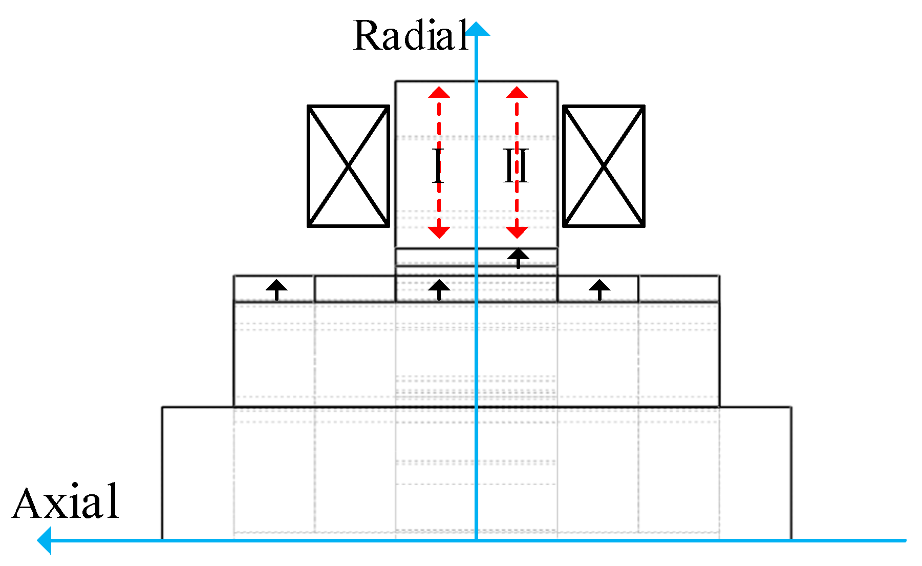
As shown in Figure 11, the stator is divided into two sections along the axial direction for finite element simulation because of the symmetry of electromagnetic force distribution. Sections I and II are at 4.5 mm and −4.5 mm in the axial direction, respectively.
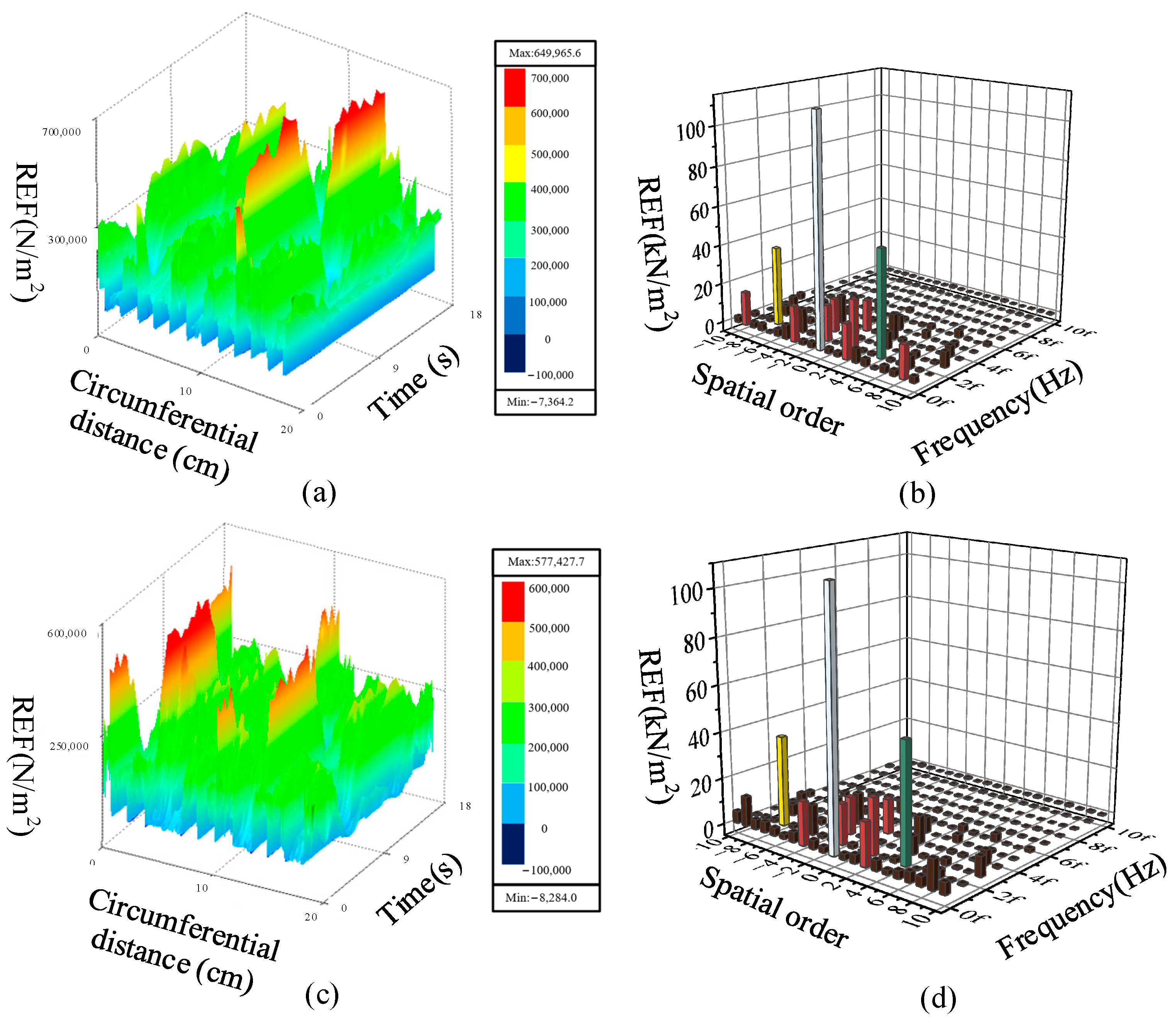
The REF distribution and its FFT under no-load state are shown in Figure 12. It can be seen that within an electrical cycle, the REF distribution of sections I and II are the same, and they are staggered by one pole distance from each other in phase. Therefore, it is only necessary to analyze the REF of one section.
It can be seen from Figure 12b,d that the amplitude of the DC component at (0, 0f) is the largest, which is mainly produced by the superposition of br and bz. The DC component has no effect on the vibration of the motor; however, other low-order and low-frequency harmonics have a significant impact on the electromagnetic vibration.
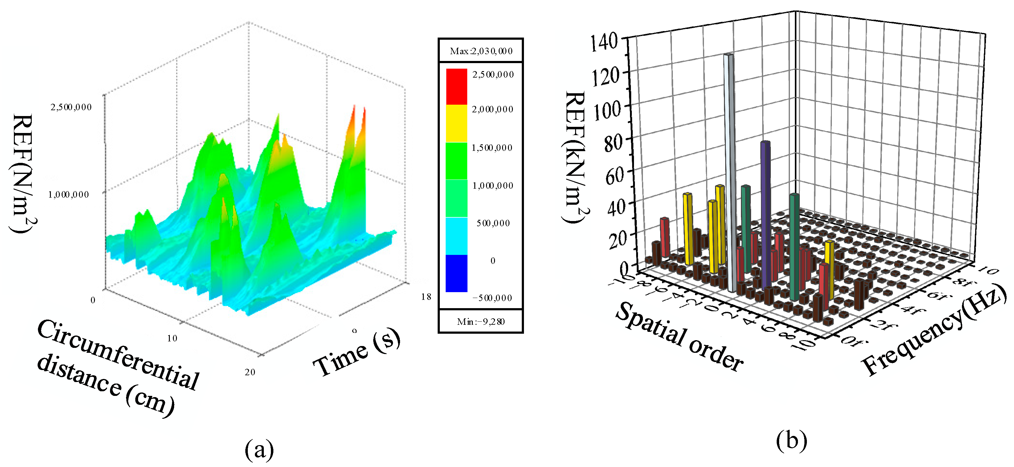
The 10A sinusoidal alternating current is applied to the winding to investigate the effect of armature flux density on the spectral characteristics of REF. The spatiotemporal distribution and FFT of REF in section I are shown in Figure 13. It can be seen that compared to the no-load state, the armature flux density increases the (2, 1f), (−5, 2f), (7, 2f) and (−4, 1f) components of REF, which are generated by the interaction between the armature flux density and PM flux density.

4. Influence of Mover Eccentricity on the Spectral Characteristics of REF

The TFPMLSM is composed of multiple motors connected in a series and has a slender structure. The eccentricity may happen as the mover is in motion, which could affect the electromagnetic performance and system stability of the motor. The influence of mover eccentricity on the spectral characteristics of REF is analyzed in this part to provide a theoretical basis for the operational reliability of TFPMLSM.

4.1. The Influence of Eccentricity on the Spectral Characteristics of Electromagnetic Forces

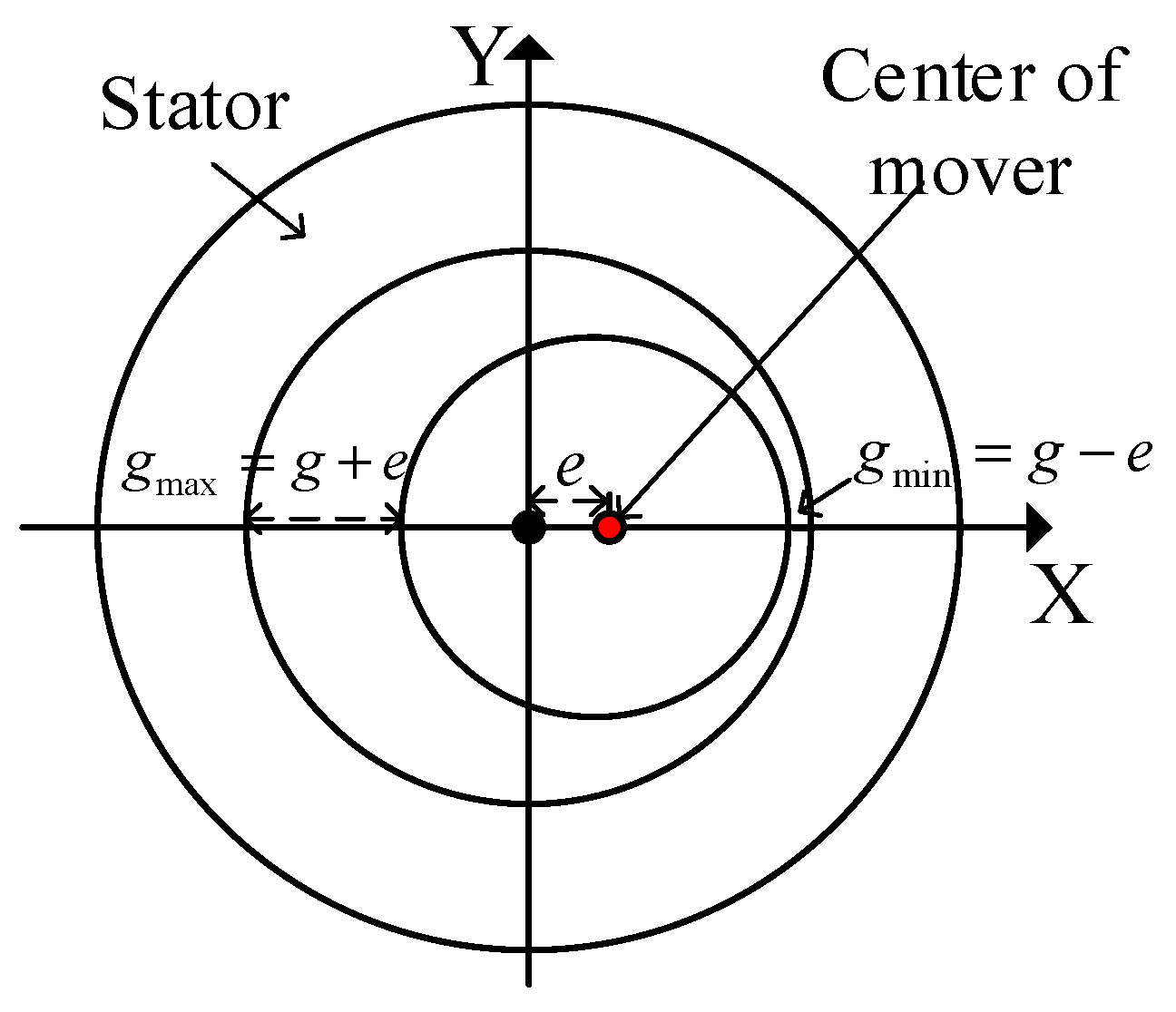
The TFPMLSM mainly experiences static eccentricity. As shown in Figure 14, the geometric center of the mover axis is not coincident with the stator axis, but deviates by a certain distance.
The eccentricity can be defined as the deviation e to the air gap g. When the mover is eccentric e along the positive X-axis direction, the air gap on the right side of the stator decreases, and the distribution of air gap flux density changes, resulting in a significantly unbalanced electromagnetic force. It manifests as an increase in the harmonics of the electromagnetic force in the spectrum.
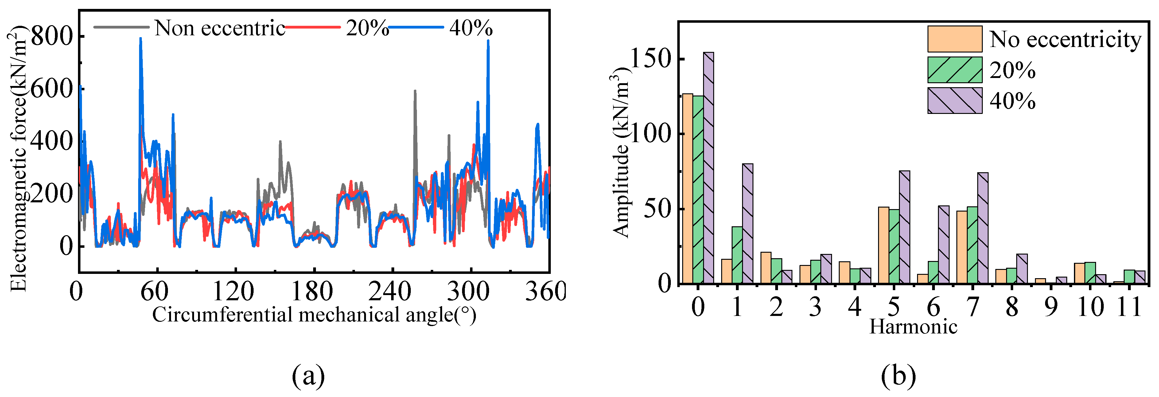
The space distribution of the REF along the circumference and its FFT under different eccentricities are shown in Figure 15. Figure 15a shows that the REF is symmetrically distributed within a mechanical cycle when there is no eccentricity. The higher the degree of eccentricity, the greater the fluctuation amplitude of the REF. Figure 15b shows that mover eccentricity not only increases the amplitude of the original order forces, but also generates new order forces, which have a significant impact on the vibration noise of the motor.
Figure 16 shows the time distribution and FFT of REF under the stator iron pole. It can be seen that the growth of eccentricity will increase the amplitude of REF.

4.2. Analysis of Unbalanced Electromagnetic Force under Mover Eccentricity

The magnetic pulling force of the entire stator can be obtained by stacking the REF on each tooth surface. Figure 17 shows the time distribution of REF under different eccentricities in the no-load state. The DC component of combined REF is 0 when the mover is not eccentric and the REF increases with the increase in eccentricity.
Figure 18 presents the distribution of axial electromagnetic force (AEF) under different eccentricities. It can be seen that as eccentricity occurs, the amplitude of AEF fluctuations increases because the PM flux density is modulated by the eccentric permeance and results in a new harmonic component of AEF. The higher the eccentricity, the greater the fundamental amplitude of the AEF.
The following conclusion can be drawn by analyzing the REF and AEF of the motor under different eccentricities: a large magnetic pull in the radial direction will be produced as the mover eccentricity occurs, and the thrust fluctuation amplitude of the motor increases, which will affect the motor load-carrying capacity.

5. Analysis of Stator Mode and Electromagnetic Vibration of TFPMLSM

REF acts on stator teeth as an excitation force with the operation of motor. It will cause resonance and endanger the safety and stability of the system when the frequency of REF is close to the natural frequency of the motor and the spatial order of the REF matches the vibration mode of the motor. The order of the vibration mode and natural frequency of the motor can be obtained by modal analysis, which provides a theoretical basis for avoiding the resonance.

5.1. Characteristics of Stator Modal by Finite Element Analysis

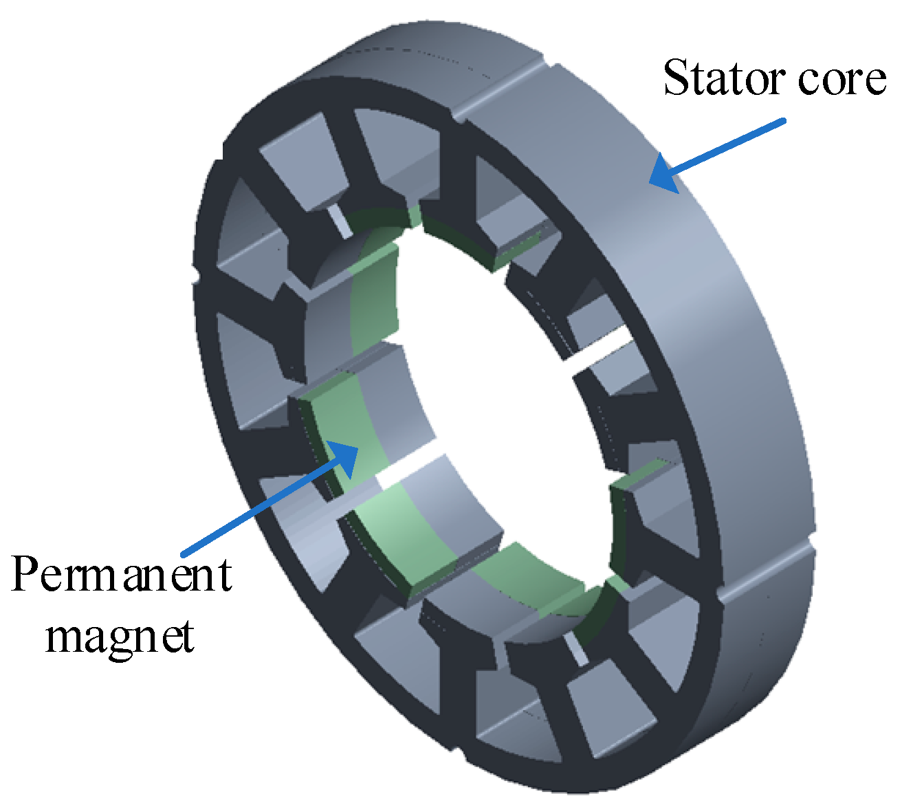
The stator of the TFPMLSM is composed of the stator combination of multiple unit motors. The ratio of its axial length to outer diameter is as high as 20–50, and the influence of the electromagnetic force on the axial vibration is small. Therefore, the radial mode and low-order axial mode are mainly analyzed in this paper. The coils that have little impact on the vibration are ignored to simplify the computation and a simplified stator model is obtained as shown in Figure 19. The material parameters are shown in Table 2.
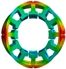
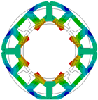
The MSM is used to calculate the 2–4 modal vibration modes and natural frequencies of the motor, as shown in Table 3. From the previous analysis, the fundamental and second harmonics have the greatest impact on the electromagnetic vibration. When the mover moves at the maximum speed of 1 m/s, the fundamental and second harmonic frequencies of the motor are 55.56 Hz and 111.11 Hz respectively, which is quite different from each natural frequency of the motor and the resonance will not occur.
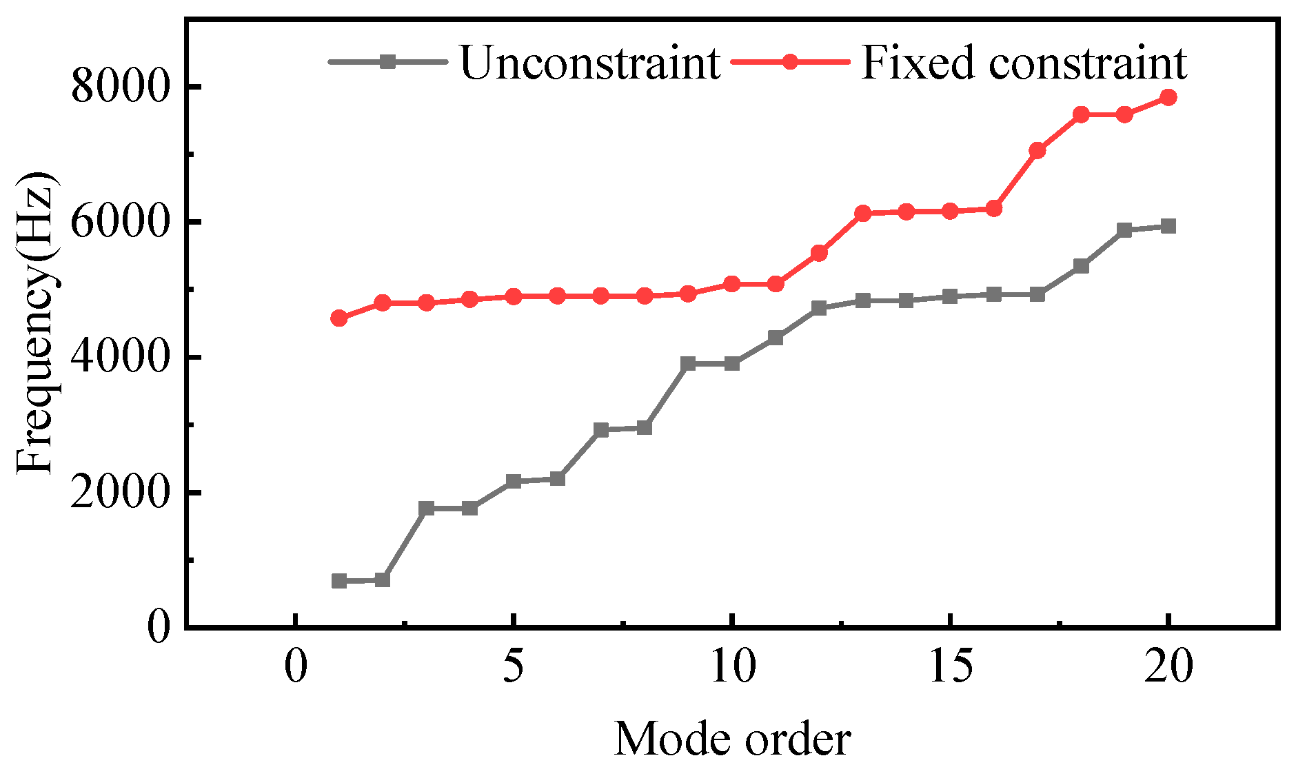
The submersible motors often need to be slotted into the stator to be fixed in the casing, therefore, the unconstraint and fixed constraint are set at the stator slot, respectively, to obtain the relationship between the mode order and natural frequency, as shown in Figure 20. It can be seen that for the motor with fixed constraint, each natural frequency of stator is high. However, the fundamental working frequency of TFPMLSM is no more than 55.56 Hz, which is much lower than each natural frequency, resulting in a low probability of resonance.

5.2. Harmonic Response Analysis

The FEM is used to conduct magnetic-structural coupling analysis. The stator tooth surface and outer surface are selected as the vibration measurement surfaces to observe the vibration characteristics of the motor, as shown in Figure 21.
The vibration velocity response of the measuring surface is shown in Figure 22. It can be found that the vibration response law of the stator outer surface is roughly the same as that of the stator tooth surface. The fundamental frequency of REF has the greatest impact on the vibration, and it also causes a large radial vibration response at 666 Hz (12 times frequency).
Figure 23 shows the vibration response at 40% eccentricity towards X direction. Figure 23a presents that the electromagnetic vibration amplitude of the stator teeth increases in all directions after eccentricity. Figure 23b shows that the eccentricity increases the electromagnetic vibration response amplitude in the X and Y directions of the outer surface, while the vibration amplitude in the Z direction is basically unchanged.

6. Conclusions

Due to its special magnetic circuit, the REF and vibration characteristics of the TFPMLSM is different from other motors. Considering its long-term underground working environment, the eccentricity could also significantly affect the vibration performance. To reveal the electromagnetic vibration characteristics and the impact of eccentricity on vibration, the air gap flux density is firstly calculated and the REF which is the source of electromagnetic vibration is investigated by FEM. The influence of mover eccentricity on REF is then analyzed and the electromagnetic vibration response is obtained. The following conclusions can be drawn according to the research of this paper.
  • Based on the Maxwell tensor method, it is obtained that the REF of the TFPMLSM is not only related to the radial flux density component, but also to the axial component, which is different from traditional longitudinal flux motors.
  • A large magnetic pull in the radial direction will be produced as the mover eccentricity occurs, and the thrust fluctuation amplitude of the motor increases, which will affect the motor load-carrying capacity.
  • The natural frequencies of the motor are obtained based on MSM. Compared to the fundamental working frequency, which is 55.56 Hz at maximum speed of 1 m/s, each natural frequency of the motor is much higher, therefore, resonance will not occur at a low speed.
  • The fundamental frequency of the electromagnetic force has the greatest impact on the electromagnetic vibration of the TFPMLSM, which is different from the traditional rotating motor.

Author Contributions

Conceptualization, M.Z.; Methodology, M.Z.; Software, P.T. and S.Z.; Validation, P.T.; Formal analysis, P.T., S.Z. and T.Y.; Investigation, H.Z.; Data curation, S.Z. and S.W.; Writing—original draft, Y.L.; Writing—review and editing, Y.L.; Visualization, H.Z.; Supervision, M.Z.; Project administration, H.Z. and T.Y. All authors have read and agreed to the published version of the manuscript.

Funding

This work was supported in part by the National Natural Science Foundation of China under Project 52177032 and the Key Laboratory of Special Machine and High Voltage Apparatus (Shenyang University of Technology), Ministry of Education (KFKT202107).

Data Availability Statement

Data are contained within the article.

Conflicts of Interest

The authors declare no conflict of interest. The funders had no role in the design of the study; in the collection, analyses, or interpretation of data; in the writing of the manuscript; or in the decision to publish the results.

References

  1. Smadi, I.A.; Omori, H.; Fujimoto, Y. Development, analysis, and experimental realization of a direct-drive helical motor. IEEE Trans. Ind. Electron. 2012, 59, 2208–2216. [Google Scholar] [CrossRef]
  2. Fujimoto, Y.; Kominami, T.; Hamada, H. Development and analysis of a high thrust force direct-drive linear actuator. IEEE Trans. Ind. Electron. 2009, 56, 1383–1392. [Google Scholar] [CrossRef]
  3. Wang, J.; Wang, W.; Jewell, G.W.; Howe, D. A low-power, linear, permanent-magnet generator/energy storage system. IEEE Trans. Ind. Electron. 2002, 49, 640–648. [Google Scholar] [CrossRef]
  4. Colli, V.D.; Cancelliere, P.; Marignetti, F.; Stefano, R.D.; Scarano, M. A tubular-generator drive for wave energy conversion. IEEE Trans. Ind. Electron. 2006, 53, 1152–1159. [Google Scholar] [CrossRef]
  5. Zhao, M.; Zou, J.M.; Xu, Y.X.; Zou, J.B.; Wang, Q. The thrust characteristic investigation of transverse flux tubular linear machine for electromagnetic launcher. IEEE Trans. Plasma Sci. 2011, 39, 925–930. [Google Scholar] [CrossRef]
  6. Zou, J.; Zhao, M.; Wang, Q.; Zou, J.; Wu, G. Development and analysis of tubular transverse flux machine with permanent magnet excitation. IEEE Trans. Ind. Electron. 2012, 59, 2198–2207. [Google Scholar] [CrossRef]
  7. Zhao, J.; Mou, Q.; Guo, K.; Liu, X.; Li, J.; Guo, Y. Reduction of the detent force in a flux-switching permanent magnet linear motor. IEEE Trans. Energy Convers. 2019, 34, 1695–1705. [Google Scholar] [CrossRef]
  8. Suzuki, K.; Kim, Y.J.; Dohmeki, H. Driving method of permanent magnet linear synchronous motor with the stationary discontinuous armature for long-distance transportation system. IEEE Trans. Ind. Electron. 2012, 59, 2227–2235. [Google Scholar] [CrossRef]
  9. Lu, Q.; Li, Y.; Huang, X.; Ye, Y. Analysis of transverse-flux linear switched-flux permanent magnet machine. IEEE Trans. Magn. 2015, 51, 1–4. [Google Scholar] [CrossRef]
  10. Ueda, Y.; Takahashi, H.; Akiba, T.; Yoshida, M. Fundamental design of a consequent-pole transverse-flux motor for direct-drive systems. IEEE Trans. Magn. 2013, 49, 4096–4099. [Google Scholar] [CrossRef]
  11. Zhang, B.; Epskamp, T.; Doppelbauer, M.; Gregor, M. A comparison of the transverse, axial and radial flux PM synchronous motors for electric vehicle. In Proceedings of the IEEE International Electric Vehicle Conference, Florence, Italy, 17–19 December 2014. [Google Scholar]
  12. Jang, I.S.; Ham, S.H.; Kim, W.H.; Jin, C.S.; Cho, S.Y.; Lee, K.D.; Lee, J.J.; Kang, D.; Lee, J. Method for analyzing vibrations due to electromagnetic force in electric motors. IEEE Trans. Magn. 2014, 50, 297–300. [Google Scholar] [CrossRef]
  13. Islam, R.; Husain, I. Analytical model for predicting noise and vibration in permanent-magnet synchronous motors. IEEE Trans. Ind. Appl. 2010, 46, 2346–2354. [Google Scholar] [CrossRef]
  14. Islam, M.S.; Islam, R.; Sebastian, T. Noise and vibration characteristics of permanent-magnet synchronous motors using electromagnetic and structural analyses. IEEE Trans. Ind. Appl. 2014, 50, 3214–3222. [Google Scholar] [CrossRef]
  15. Cho, S.; Hwang, J.; Kim, C.-W. A study on vibration characteristics of brushless DC motor by electromagnetic-structural coupled analysis using entire finite element model. IEEE Trans. Energy Convers. 2018, 33, 1712–1718. [Google Scholar] [CrossRef]
  16. Lu, Y.; Li, J.; Qu, R.; Ye, D.; Lu, H.; Sun, J.; Ge, M.; Xu, H. Electromagnetic force and vibration analysis of permanent-magnet-assisted synchronous reluctance machines. IEEE Trans. Ind. Appl. 2018, 54, 4246–4256. [Google Scholar] [CrossRef]
  17. Li, J.; Cho, Y. Investigation into reduction of vibration and acoustic noise in switched reluctance motors in radial force excitation and frame transfer function aspects. IEEE Trans. Magn. 2009, 45, 4664–4667. [Google Scholar]
  18. Wang, S.; Hong, J.; Sun, Y.; Cao, H. Analysis and reduction of electromagnetic vibration of PM brush DC motors. IEEE Trans. Ind. Appl. 2019, 55, 4605–4612. [Google Scholar] [CrossRef]
  19. He, G.; Huang, Z.; Chen, D. Two-dimensional field analysis on electro-magnetic vibration-and-noise sources in permanent-magnet direct current commutator motors. IEEE Trans. Magn. 2011, 47, 787–794. [Google Scholar] [CrossRef]
  20. Wu, S.; Zuo, S.; Wu, X.; Lin, F.; Zhong, H.; Zhang, Y. Vibroacoustic prediction and mechanism analysis of claw pole alternators. IEEE Trans. Ind. Electron. 2016, 64, 4463–4473. [Google Scholar] [CrossRef]
  21. Sun, T.; Kim, J.M.; Lee, G.H.; Hong, J.P.; Choi, M.R. Effect of pole and slot combination on noise and vibration in permanent magnet synchronous motor. IEEE Trans. Magn. 2011, 47, 1038–1041. [Google Scholar] [CrossRef]
  22. Luo, J.; Kou, B.; Yang, X.; Zhang, H.; Zhang, L. Development, design, and analysis of a dual-consequent-pole transverse flux linear machine for direct-drive applications. IEEE Trans. Ind. Electron. 2020, 68, 6097–6108. [Google Scholar] [CrossRef]
  23. Zheng, P.; Zhu, S.; Yu, B.; Cheng, L.; Fan, Y. Analysis and optimization of a novel tubular staggered-tooth transverse-flux PM linear machine. IEEE Trans. Magn. 2015, 51, 1–4. [Google Scholar] [CrossRef]
  24. Sui, Y.; Yin, Z.; Wang, M.; Yu, B.; Zheng, P. A tubular staggered-teeth transverse-flux PMLM with circumferentially distributed three-phase windings. IEEE Trans. Ind. Electron. 2018, 66, 4837–4848. [Google Scholar] [CrossRef]
  25. Arshad, W.M.; Thelin, P.; Backstrom, T.; Sadarangani, C. Use of transverse-flux machines in a free-piston generator. IEEE Trans. Ind. Appl. 2004, 40, 1092–1100. [Google Scholar] [CrossRef]
  26. Liu, J.; Li, X.; Yan, B.; Hua, W.; Wang, X. Electromagnetic performance analysis of a field-modulated permanent magnet motor using improved hybrid subdomain method. IEEE Trans. Energy Convers. 2023, 38, 1753–1766. [Google Scholar] [CrossRef]
  27. Li, X.; Wei, Z.; Zhao, Y.; Wang, X.; Hua, W. Design and Analysis of Surface-Mounted Permanent-Magnet Field-Modulation Machine for Achieving High Power Factor. IEEE Trans. Ind. Electron. 2023. early access. [Google Scholar] [CrossRef]
  28. Li, X.; Liu, S.; Wang, Q.; Yan, B.; Huang, Z.; Wang, K. Performance investigation and experimental testing of a stator-PM-excitation axial-flux magnetic gear. IEEE Trans. Transp. Electrif. 2022, 9, 2593–2605. [Google Scholar] [CrossRef]
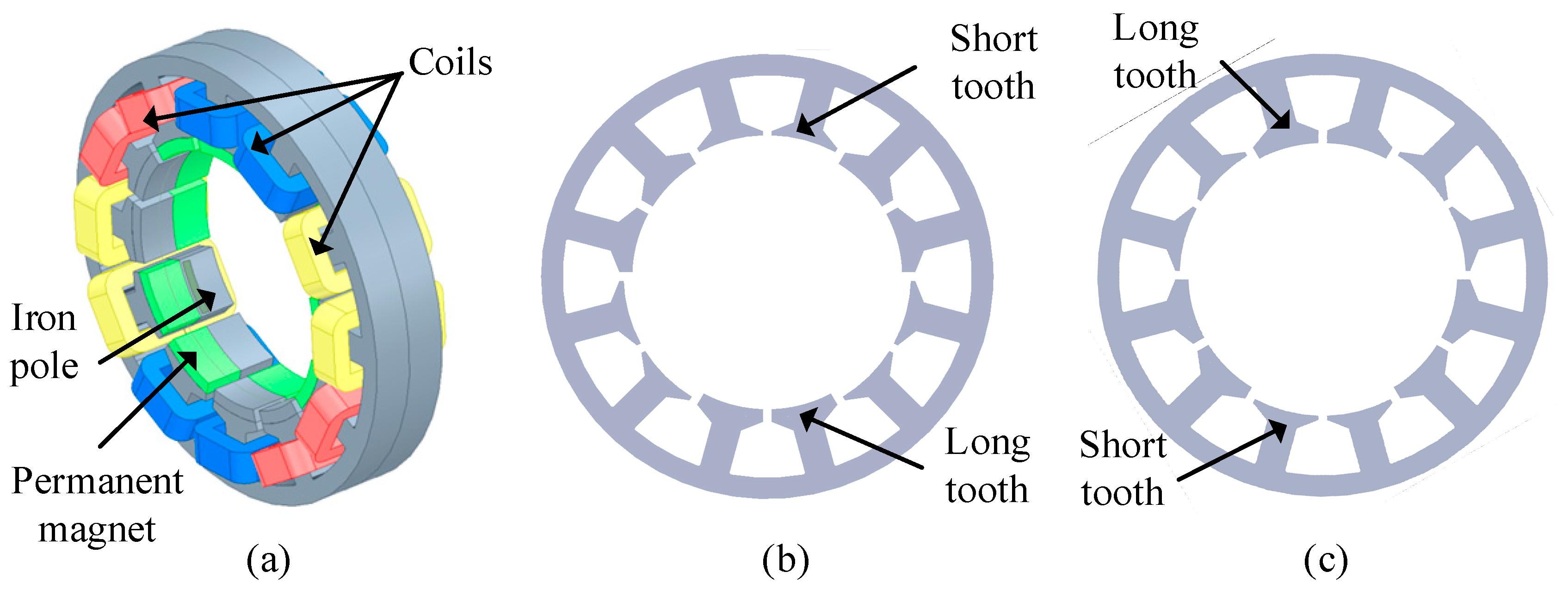
Figure 1. Primary structure of the transverse flux permanent magnet linear submersible motor (TFPMLSM): (a) primary unit; (b) lamination A of primary iron core; (c) lamination B.
Energies 16 07911 g001
Figure 2. Secondary structure of TFPMLSM: (a) mover; (b) lamination C of secondary iron core; (c) lamination D.
Energies 16 07911 g002
Figure 3. The arrangement of the mover iron poles.
Energies 16 07911 g003
Figure 4. 3-D finite element model of the TFPMLSM.
Energies 16 07911 g004
Figure 5. Size parameters of motor. (a) Front view of motor. (b) Side view of motor.
Energies 16 07911 g005
Figure 6. Axial flux path of TFPMLSM.
Energies 16 07911 g006
Figure 7. Flux path of one sixth single-phase TFPMLSM model. (a) Maximum flux path in a positive direction. (b) Maximum flux path in a negative direction.
Energies 16 07911 g007
Figure 8. MMF distribution of PMs and permeance distribution of iron poles. (a) Modal of stator PMs and mover iron poles; (b) modal of mover PMs and stator iron poles; (c) permeance of mover iron poles; (d) permeance of stator iron poles; (e) MMF of stator PMs; (f) MMF of mover PMs.
Energies 16 07911 g008
Figure 9. Electromagnetic force in three directions.
Energies 16 07911 g009
Figure 10. Air gap flux density distribution under tooth II.
Energies 16 07911 g010
Figure 11. Axial segmentation of the TFPMLSM.
Energies 16 07911 g011
Figure 12. REF distribution and its FFT under no-load state. (a) The spatiotemporal distribution of REF (section I); (b) harmonic distribution (section I); (c) the spatiotemporal distribution of REF (section II); (d) harmonic distribution (section II). Note that different colors in (b) and (d) represent different magnitudes of REF.
Energies 16 07911 g012
Figure 13. REF distribution and its FFT under load state. (a) The spatiotemporal distribution of REF; (b) harmonic distribution. Note that different colors in (b) represent different magnitudes of REF.
Energies 16 07911 g013
Figure 14. Static eccentricity of mover.
Energies 16 07911 g014
Figure 15. Spatial distribution and harmonics of REF versus eccentricity. (a) Spatial distribution of REF; (b) harmonic distribution.
Energies 16 07911 g015
Figure 16. Time distribution and harmonic of axial electromagnetic force versus eccentricity. (a) Time distribution of REF; (b) harmonic distribution.
Energies 16 07911 g016
Figure 17. Time distribution of REF and its DC component versus eccentricity. (a) Time distribution of REF; (b) influence of eccentricity on the DC component of REF.
Energies 16 07911 g017
Figure 18. Time distribution of AEF and its DC component versus eccentricity. (a) Time distribution of AEF; (b) harmonic distribution.
Energies 16 07911 g018
Figure 19. Stator structure of modal analysis.
Energies 16 07911 g019
Figure 20. The first 20 modes and their natural frequencies under unconstraint and fixed constraint.
Energies 16 07911 g020
Figure 21. Location of vibration measurement points.
Energies 16 07911 g021
Figure 22. Electromagnetic vibration response of stator tooth surface and outer surface. (a) Stator tooth surface vibration response; (b) vibration response of stator outer surface.
Energies 16 07911 g022
Figure 23. Electromagnetic vibration response of stator tooth surface and outer surface with 40% mover eccentricity. (a) Stator tooth surface vibration response; (b) vibration response of stator outer surface.
Energies 16 07911 g023
Table 1. Structural parameters of the TFPMLSM.
ParameterSymbolValueParameterSymbolValue
Outer radius of stator iron core/mmRpo52Axial length of mover PM (Pole distance)/mmτ9
Stator slot height/mmhpt10.8Inner radius of mover iron core/mmRsi15
Axial length of stator PM/mmlpm8Stator PM height/mmhPM3
Stator yoke height/mmhpy5Mover PM height/mmhst3
Stator tooth width/mmwpt7Mover pole arc coefficientαst0.8
Air gap/mmg1Stator slot width/mmwpo3.5
Radius of mover cylinder/mmRso27.4
Table 2. Material properties of stator.
Material NameModel NumberDensity (kg/m3)Young’s Modulus (Gpa)Young’s Modulus
Silicon steel sheetDW465_5077001700.26
Permanent magnetNdFe3075501600.24
Table 3. Vibration modes and natural frequencies.
Mode NumberMode ShapesNatural Frequency [Hz]
Radial 2nd modeEnergies 16 07911 i001683.75
Radial 3nd modeEnergies 16 07911 i002699.55
Axial 1st mode, radial 2nd modeEnergies 16 07911 i0031758.9
Radial 4nd modeEnergies 16 07911 i0042159.7
Disclaimer/Publisher’s Note: The statements, opinions and data contained in all publications are solely those of the individual author(s) and contributor(s) and not of MDPI and/or the editor(s). MDPI and/or the editor(s) disclaim responsibility for any injury to people or property resulting from any ideas, methods, instructions or products referred to in the content.