Article

New Reference Current Calculation Method of a Hybrid Power Filter Based on Customer Harmonic Emission

1
Faculty of Electrical Engineering, University of Ljubljana, Tržaška 25, 1000 Ljubljana, Slovenia
2
Milan Vidmar Electric Power Research Institute, Hajdrihova 2, 1000 Ljubljana, Slovenia
*
Author to whom correspondence should be addressed.
Energies 2023, 16(23), 7876; https://doi.org/10.3390/en16237876
Submission received: 29 October 2023 / Revised: 24 November 2023 / Accepted: 29 November 2023 / Published: 1 December 2023

Abstract

:
This paper presents a novel reference current calculation method for harmonics mitigation and reactive power compensation in power systems. This method was applied to a unique hybrid power filter topology. The motivation for this study comes from the increasing power quality issues, such as harmonic distortion and resonances, caused by the widespread integration of converter-interfaced generation (CIG) and modern nonlinear loads into the power system in recent years. The goal of this study is to propose a cost-effective and practical solution for current harmonics filtering and power factor correction by combining the advantages of passive and active filters into a hybrid solution. The developed reference current calculation method, which is based on customer current harmonic emissions, enables effective reference current calculation. Theoretical analyses along with simulation results obtained from a medium-voltage benchmark model in PSCAD verify the effectiveness of the proposed solution in harmonics filtering and show a substantial reduction in filter current ratings across various harmonic components. In addition, the simulation results were evaluated by comparison with the results obtained from a real-time simulator.

1. Introduction

The growing presence of power electronic-based equipment in modern power systems, driven by the widespread integration of modern nonlinear loads (e.g., electric vehicles, heat pumps) and converter-interfaced generation (CIG) units, has elevated the significance of the following two power quality parameters in particular: power factor correction and harmonic filtering. To ensure that the power quality levels stay within the limits defined by the standards [1], developing effective solutions for power quality improvement is nowadays gaining importance [1,2,3,4].
Hybrid power filters (HPFs) have emerged as promising solutions to address power quality challenges in recent years. By combining the advantages of active and passive filters, hybrid filters provide good harmonic filtering capabilities and mitigate drawbacks associated with standalone filter types—e.g., resonance problems, non-flexibility, cost-effectiveness. The integration of active and passive elements enables better control over harmonic filtering performance, reduced voltage and current ratings, and improved efficiency [5,6,7,8].
In the extensive literature on power factor correction compensators and current harmonic filtering, numerous different hybrid filter connection topologies have been proposed. The two most common variants are the series connection of an active and passive part (series HPF [9,10,11,12] and the parallel configuration of both passive and active parts [13,14,15]. In the first case, the nominal voltage required for the converter is low since most of the voltage drop occurs across the capacitor of the passive part; however, unless a coupling transformer is used, the entire fundamental component of the nominal current flows through the active filter. In the second case, with the parallel combination, only the filtered harmonic current flows through the converter (and a very small fundamental component for DC-voltage regulation), but it needs to be rated for the full nominal voltage. An extensive overview of some other topologies can be found in [16,17,18,19,20].
The proposed hybrid filter topology consists of a three-phase, three-level voltage-source converter connected in parallel with the inductor of the passive part. The main advantage of this topology is that the voltage across the converter is relatively small (a few percent of the nominal supply voltage) due to the (fundamental component) voltage drop across the capacitor of the passive part. Additionally, the fundamental component of the current through the converter is also small due to the parallel inductor.
As the topology presented consists only of single-tuned elements, the control system must ensure effective filtering of current harmonics also at other harmonic frequencies. Thus, the design of the controller is both an important and challenging task given its influence on the system’s performance and stability. The control strategies for various HPF structures, as discussed in the literature, are predominantly wideband. The proportional (P) control approach is most frequently used, typically in the synchronous reference frame (SRF) [9,14,21]. However, the high proportional constant required for effective filtering makes this control structure unsuitable for the topology proposed in this paper since it shows poor transient performance, as noted in [22]. Due to their good selectivity and improved transient performance, some authors have used a proportional-resonant current controller within the SRF [23,24,25,26,27,28,29]. Since our focus in developing the controller was on the HPF reference current calculation method that considers the customer’s contribution to the total harmonic distortion (THD) at the point of common coupling (PCC) and not primarily on control system performance, conventional vector controllers in the DQ coordinate system were used [30,31,32], which represent an established (current) control principle.
The upgraded algorithm, building on the algorithm introduced by the authors in [33], allows for the differentiation of harmonic distortions caused by nonlinear loads on the one hand and (impedance) resonance amplifications of the distortion on the other hand. This differentiation additionally reduces the need for an oversized active part of the HPF. In doing so, the algorithm relies on the reference harmonic impedances since the actual harmonic impedances are usually unavailable in practice [34].
For the evaluation of the proposed HPF topology and reference current calculation method, extensive simulations were conducted using PSCAD v. 4.6.0 software. Additionally, controller-in-the-loop (CIL) testing with a real-time digital simulator was performed to validate the PSCAD results. These simulations demonstrate the reduction in the current ratings of the active part and the good filtering performance of the HPF, validating the improved performance achieved by the proposed approach.
The novel contributions of this paper are as follows: First, we propose a novel HPF reference current calculation method, which advances the state-of-the-art of harmonic distortion mitigation by focusing on the customer’s contribution to the harmonic distortion at the PCC. This new approach allows for a more targeted application of the HPFs in both industrial and distribution power networks. In addition, this paper demonstrates the effectiveness of the presented HPF topology in reducing active part power ratings, improving its cost-effectiveness and practical value.
The structure of this paper is as follows: In Section 2, we provide an overview of the proposed HPF topology, illustrating its design and functionality. Additionally, the dimensions of the proposed HPF topology are compared with other common filter topologies, highlighting its efficiency and smaller size relative to conventional solutions. Section 3 defines the harmonic impedances that were used to determine the reference current for the HPF. In Section 4, we introduce the method for calculating the HPF’s reference current, focusing on detailing the calculation process with phasor diagrams and a flowchart. Section 5 describes the control algorithm and its implementation in simulation software. Finally, Section 6 presents simulation results, demonstrating the effectiveness of the new approach in reducing the power requirements of the active part of the HPF. We conclude with a summary of the contributions and potential future directions in Section 7.

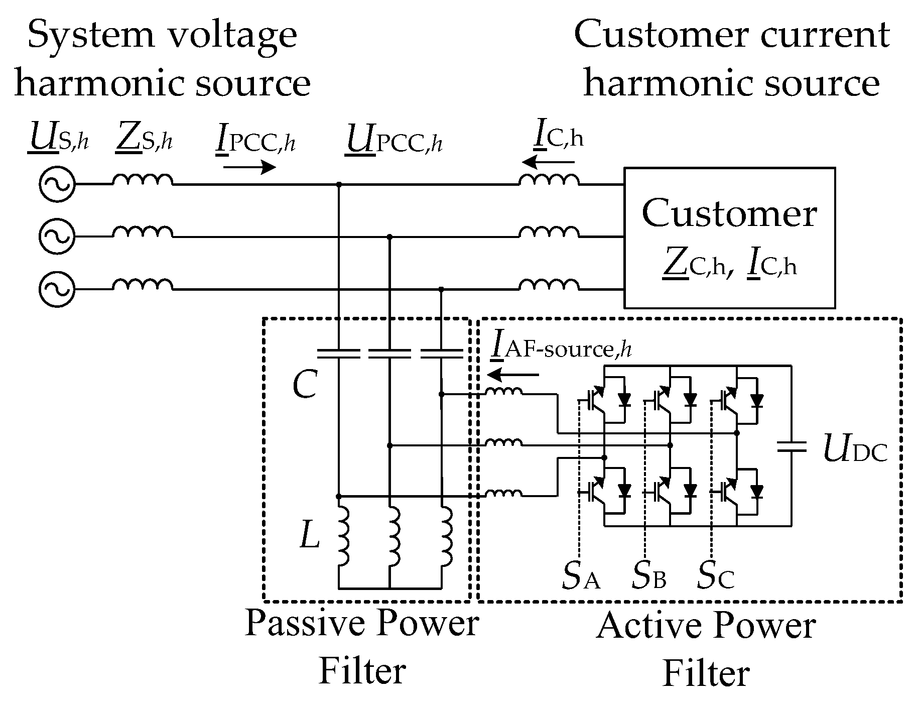
2. Hybrid Power Filter Topology

Figure 1 shows a simplified single-line diagram of the proposed HPF topology. In this topology, a customer is supplied by a balanced voltage source and filtered by the proposed HPF. A simple ripple filter (inductance) is used to reduce the high-frequency harmonic currents injected into the network.
In Figure 2, a simplified (equivalent) single-line circuit of the proposed topology is shown. It serves as a schematic from which the detailed calculations in Section 3, Section 4.1, and Section 4.2 are derived. The symbols used in the figures are as follows: UPCC,h represents the point-of-common-coupling harmonic voltage, ZS,h denotes the network harmonic impedance, which includes the short-circuit impedance and impedance of the power supply transformer in series, ZC,h represents the customer’s harmonic impedance, and IC,h the customer’s harmonic current. C stands for the capacitance of the passive filter, while R and L indicate the resistance and inductance of the passive filter. The current of the active part of the filter is represented with IAF-source,h. SABC are switching signals for the semiconductor switches of the active part, and uDC is the DC-side voltage of the converter. The active part of the HPF is presented with an ideal current source, while the load is represented with a Noorthon source ZC,h and IC,h, injecting into the network harmonic components IC,h.
Figure 3 shows the power ratings of the active part of the HPF per unit (p.u.) as a function of the tuning frequency (fr) of the passive part from 160 to 360 Hz. These calculations were performed for a hypothetical case to illustrate the required rating. The parameters used in the calculation are given in the figure.
As evident, the power is strongly dependent on the tuning frequency. Therefore, the proposed topology of the hybrid filter is most suitable for single-tuned passive filters where the tuning frequency does not deviate significantly from the harmonic frequency to be filtered. If we are filtering multiple harmonics simultaneously with a single-tuned filter, the optimal tuning frequency lies somewhere between these harmonics. However, when tuning the passive part, it is essential to consider parallel resonance between the filter and the network.
In [20], a more detailed analysis of the dimensions of the active part of the proposed filter topology was conducted, comparing them with the dimensions of the commonly used series hybrid filter and a regular active filter. As it has been shown, the dimensions of the proposed topology are approximately 1–2% of the power of the compensated load. Furthermore, the dimensions of the active part in the proposed HPF are approximately four times smaller than in a series connection and as much as forty times smaller than in a typical active filter used as a stand-alone filter.
In addition to the detailed analysis of the active part’s dimensions in the proposed HPF topology (as presented in [20]), we also evaluated the ratings of other common HPF topologies, which are graphically shown in Figure 4. While the conventional active filter typically has the largest dimensions, our proposed topology exhibits the smallest dimensions among those compared. However, it is important to note that the dimensions related to voltage and current in any HPF topology are influenced by various factors. These include, but are not limited to, the tuning frequency of the passive part (as shown in Figure 3), the required dynamic characteristics of the device, the type of load, and the voltage level of the network. Such factors play a significant role in determining the practical feasibility and performance of the HPF.

3. Reference Harmonic Impedances

In this section, the role of harmonic impedances in the HPF reference current calculation is described, using a mixed equivalent circuit in Figure 5. In this figure, the contribution of the HPF is included in the fictive harmonic distortion (UPCC-f,h and IPCC-f,h), denoted with the index ‘f’. It is also important to note that the presented reference current calculation method is designed for shunt-connected devices and considers the (potential) passive reactive power compensators at the customer’s location [33].
The customer’s harmonic current emission serves as the basis for calculating the HPF reference. It can be determined using the network fictive harmonic current at the PCC (IPCC-f,h) and the quotient of the fictive harmonic voltage at the PCC (UPCC-f,h) divided by the impedance of the HPF filter ZC,h, as follows:
I _ C , h = I _ P C C f , h U _ P C C f , h Z _ C , h .
Based on this, the projection of the total harmonic distortion at the PCC is the following:
I C p , h = I _ C , h · cos φ I _ P C C f , h φ I _ C , h .
The fictive harmonic distortion shows what the harmonic distortion would be if the HPF did not operate. It will be described in detail in Section 4.1.
The HPF reference is calculated by considering the phase angle of harmonic distortion and the projected value of the customer’s current harmonics emission.
As it is evident from the above Equation (1), the calculation of the HPF reference current is also dependent on the harmonic impedances. Calculating these impedances can represent a challenge. Namely, the actual harmonic impedances can only be calculated for a certain operating point, which changes during the normal operation of the system. To address this variability, reference harmonic impedances are introduced below.
First, harmonic impedances are divided into those on the customer side and those on the system side. The system-side reference harmonic impedances (ZS,h) are calculated from the short-circuit impedances and other potential equivalent impedances of the system side. Another way of calculating these impedances (used in the paper) is simply by just considering the actual harmonic impedances of the fundamental component as:
Z _ S , h = R S + j ω L S · h .
On the other hand, the reference harmonic impedances on the customer’s side are based on the active power at 50 Hz (fundamental component). Since the consumer should compensate for all reactive power and is also responsible for the harmonic distortion that arises due to resonance on the customer’s side, a reference scenario is assumed in which all customers behave as pure resistive loads (perfect compensation of reactive power) [35]. The customer’s reference harmonic impedances can be expressed by:
Z _ C , h = R C = U _ 1 2 P 1 = U _ 1 I _ 1 · cos φ 1 .
It is very important to note a further benefit of using reference impedances, which is their inherent capability to account for resonances.

4. Reference Current Determination

Building on the basic approach detailed in [34], this upgraded method focuses on accurately determining the reference current for the active part of the HPF based on the customer’s harmonic currents emissions. The overall objective of this approach is to isolate and filter harmonic currents originating from the customer’s devices at the PCC. Through such separation, the active component of the HPF becomes optimally sized, thus also economical, to address the harmonic distortion of the customer.
Figure 2 above presents a single-line diagram of the proposed topology, including the system’s contribution through a harmonic voltage source. Such representation of the background distortion is typical since the customer side is typically represented by a harmonic current source.

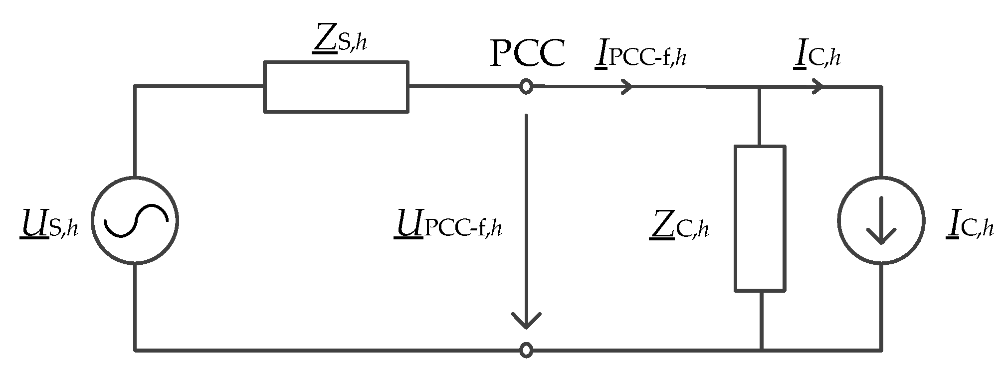
4.1. Harmonic Distortion without Hybrid Power Filter

To determine the potential harmonic distortion at the PCC without the effects of the HPF, we employ the concept of ‘hypothetical’ or ‘fictive’ (index ‘f’) harmonic distortion for the voltage and current. This approach considers the harmonic current produced by the hybrid filter, giving an insight into what the harmonic distortion at the PCC would be without the HPF’s contribution. The calculations for this fictive harmonic are represented by the equations below.
I _ P C C f , h = I _ P C C , h I _ A F S , h ,
U _ P C C f , h = U _ P C C , h I _ A F S , h · Z _ S , h ,
where I _ A F S , h represents the harmonic current flowing through the system impedance due to the HPF. This harmonic current is determined based on the ratio between the system harmonic impedance and the customer harmonic impedance as follows:
I _ A F S , h = I _ A F , h · Z _ S , h Z _ C , h + Z _ S , h ,
where I _ A F , h denotes the harmonic current flowing into the PCC from the HPF. This harmonic current is influenced not only by the system and customer harmonic impedances but also by the harmonic impedance of the passive elements within the hybrid filter (Zimp,spec.,h).
I _ A F , h = I _ A F s o u r c e , h · Z _ i m p . s p e c . , h .
The fictive harmonic distortion at the PCC can be classified as follows: The first component represents the harmonic current resulting from the background distortion, and the second component represents the harmonic current caused by the customer’s harmonic current emissions.
The second component, corresponding to the customer’s emission, requires filtering by the HPF.

4.2. Customer Harmonics Emissions and Hybrid Filter Current Reference

4.2.1. Hybrid Power Filter Current Reference

The reference for the HPF current is based on the customer’s harmonic current emissions at the PCC. These emissions are determined using the principle of superposition. They are given by:
I _ C S P , h = I _ P C C f , h · Z _ C , h Z _ C , h + Z _ S , h U _ P C C f , h Z _ C , h + Z _ S , h .
To optimize the hybrid filter’s efficiency, the customer emissions are projected to the fictive harmonic distortion. This is represented by:
I r e f A F , h = I _ C S P , h · cos φ I _ P C C f , h φ I _ C S P , h .
Finally, the harmonic current at the system side, corresponding to the portion of the PCC harmonic current caused by the background distortion, takes the form:
I r e f S , h = I _ P C C f , h I C p , h .
Iref-S,h represents the residual harmonic current at the PCC. It is important to note that the phase angle matches that of the fictive harmonic current at the PCC. Selecting the appropriate phase angle is crucial because it affects the harmonic distortion, which subsequently impacts the performance of the HPF.

4.2.2. Evaluating Filtering Requirements

Based on the (scalar) values of the HPF current reference, the filtering requirements can differ as follows:
When a scalar value Iref-AF,h is negative, the HPF needs to filter the entire harmonic distortion at the PCC (IPCC-f,h).
On the other hand, a scalar value that is larger than the fictive harmonic distortion (IPCC-f,h) means that existing equipment, possibly from other customers, has already mitigated the distortion. Thus, further filtering by the HPF becomes unnecessary. This is mathematically represented by:
I r e f A F , h = I _ P C C f , h ; 0 ;             I r e f A F , h < 0 I r e f A F , h > I _ P C C f , h .
The hybrid filter also has an impact on the harmonic voltage at the PCC depending on the conditions in the network. It has the capability to either increase or decrease the harmonic voltage, and the hybrid filter’s reference must account for the voltage harmonic distortion at the PCC. Thus, in this mode of operation, the HPF assesses whether the voltage harmonic distortion will decrease or increase and will only operate when there is a reduction in voltage harmonic distortion. Such conditions arise when the background distortion exceeds the measured harmonic distortion. At this operating point, there is no need for the HPF to further filter the harmonic distortion. Mathematically, such conditions are given by:
I r e f A F , h = I _ P C C f , h ; I r e f A F , h ;             U _ S , h U _ P C C f , h U _ S , h < U _ P C C f , h .

4.3. Phasor Diagram of the Hybrid Power Filter Current Reference Calculation

For clarity, in Figure 6 a phasor diagram of the current reference calculation method is shown. As can be seen from the figure, two cases are depicted: a theoretical (ideal) diagram (b) and a more realistic diagram (c), both representing current conditions after the HPF starts with the operation.
The color scheme in the phasor diagram is as follows:
Red: representation of the system;
Blue: customer representation;
Black: measured harmonic current at the PCC;
Green: HPF current.
In the depicted ideal case (refer to Figure 6b), the phase angles of the currents remains unchanged after filtering. The main change observed is the amplitude drop in the measured current harmonic.
On the other hand, in the more realistic case (Figure 6c), we observe a more complex situation. In addition to the potential amplitude change, the phase angles might also experience shifts. These changes arise from variations in the PCC harmonic current. For comparison, Figure 6a shows the conditions before the HPF starts with the operation.

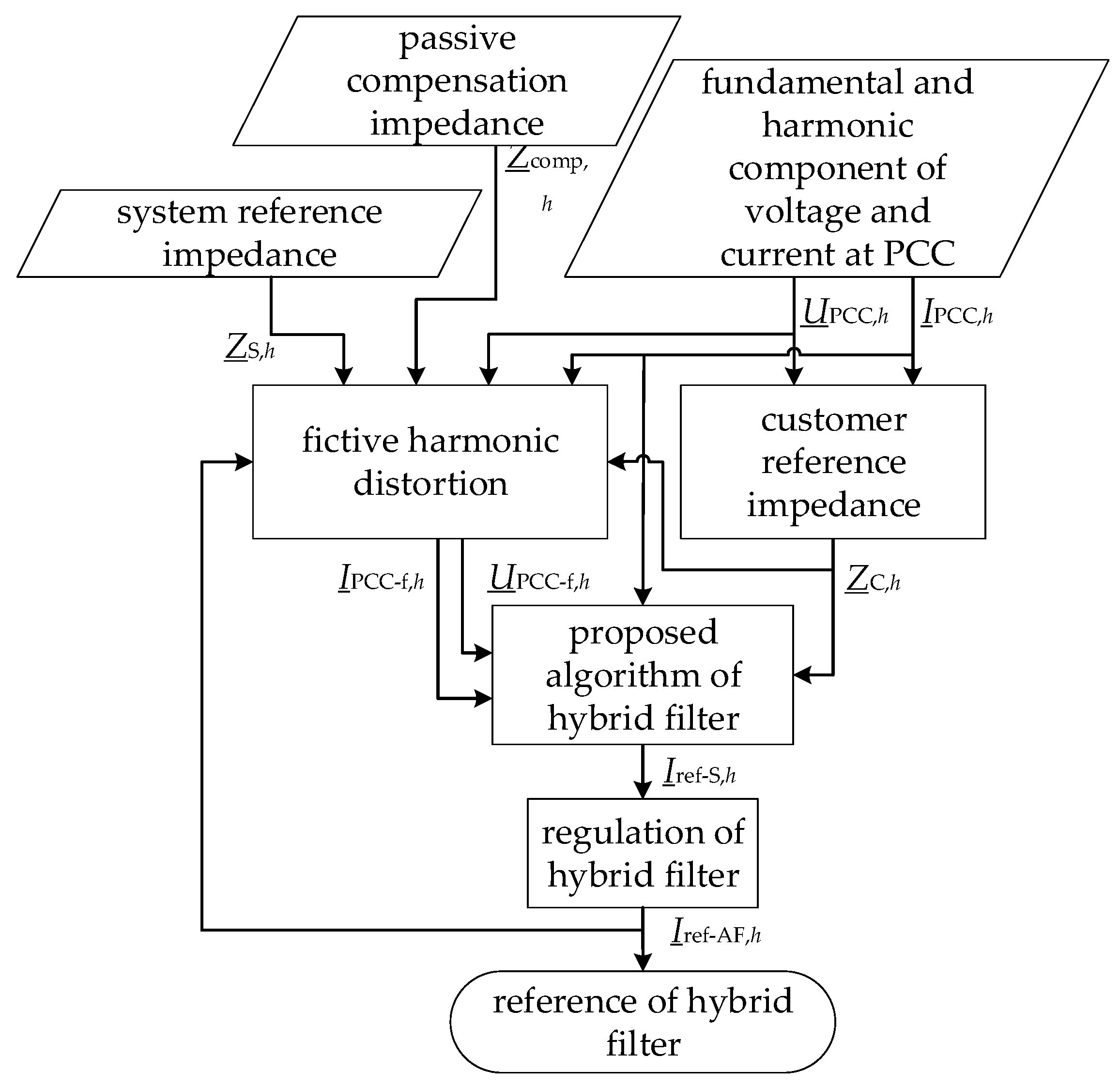
4.4. Reference Calculation Flowchart

The flowchart shown in Figure 7 illustrates the HPF reference calculation process. This calculation takes into account the impedances of passive elements, the reference harmonic impedances, and the measured harmonic distortion at the PCC. In the next step, the fictive voltage and current harmonic distortions, as well as the customer’s reference impedance, are determined. Based on these parameters, the system reference is established, indicating the residual harmonic current at the PCC. Finally, the harmonic current that the HPF needs to filter is determined.

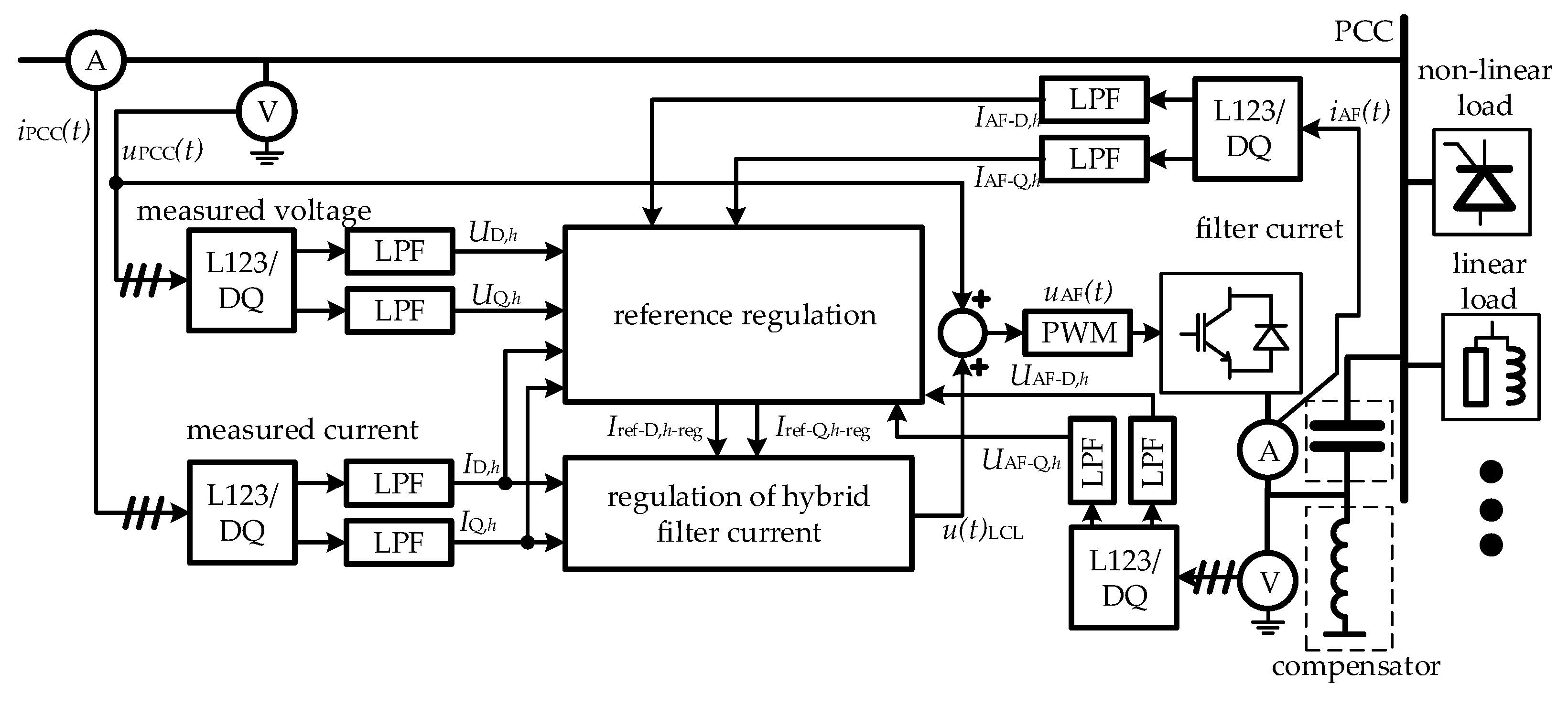
5. Hybrid Power Filter Control Algorithm

The proposed HPF reference is based on the active filter reference, as explained in [34]. The conventional vector controller is used to individually regulate each harmonic component. The control block diagram of the algorithm is shown in Figure 8. The active part of the HPF is placed between the inductor and capacitor of the passive part to reduce the fundamental component voltage and current ratings. The DQ-transformation is utilized to extract each harmonic component. The proposed HPF control algorithm consists of two main control loops. The first loop calculates the reference, while the second loop controls the HPF current.

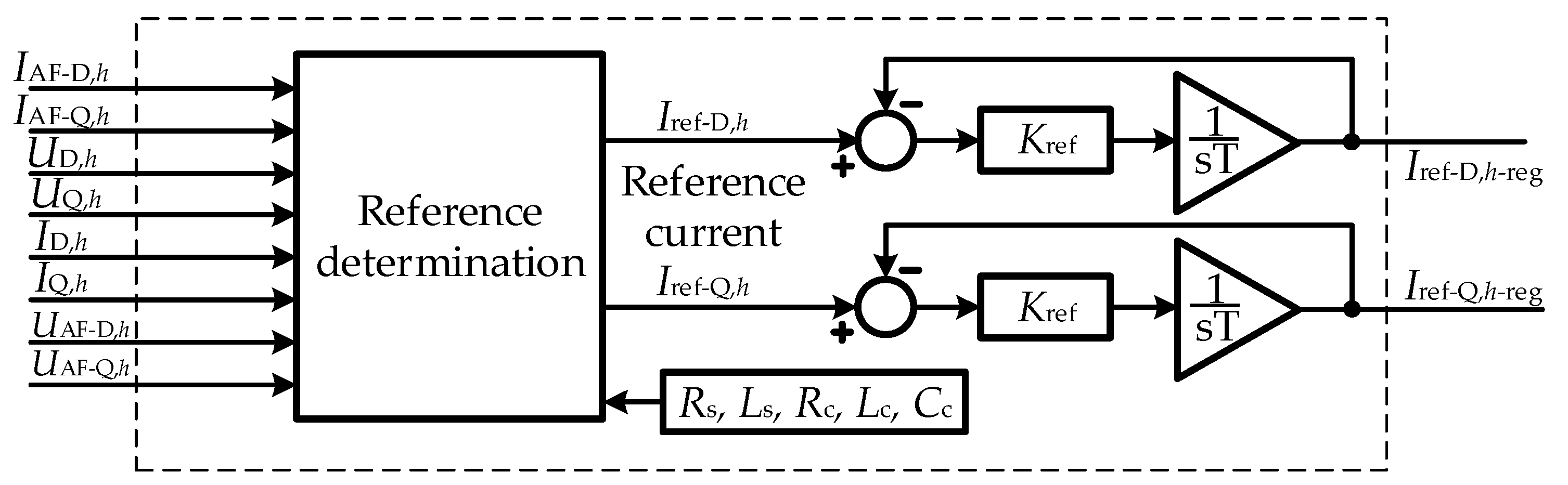
5.1. Reference Control

The output of the reference controller is the reference for the HPF current. As depicted in Figure 9, the inputs to this process are the impedances of the hybrid filter’s passive elements and the DQ-components of the measured voltages and currents. The reference is then adjusted by PI control law. The output values from the PI controller represent the inputs for the main current control loop, shown in Figure 10.

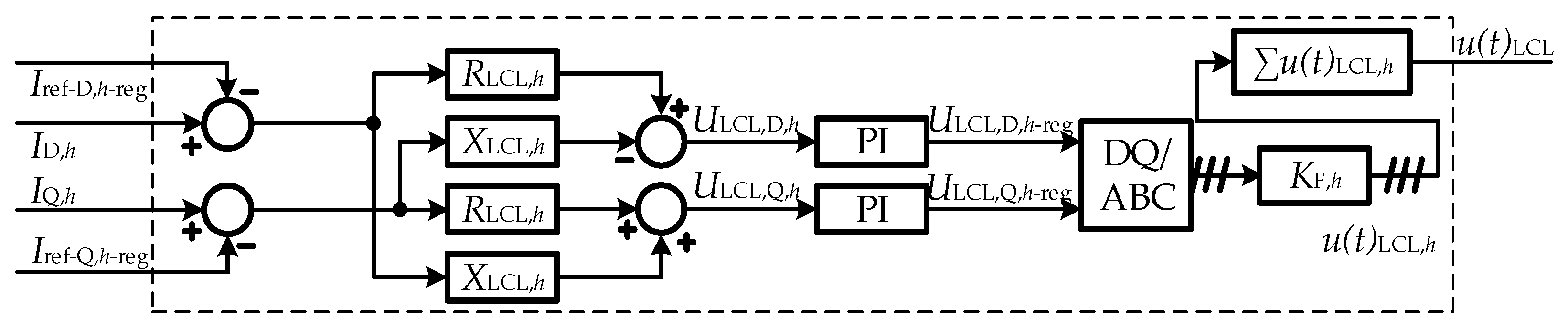
5.2. Main Current Control Block Diagram

Figure 10 shows the main current control loop, which first subtracts the regulated filter current from the measured harmonic current, controlling the voltage drop over the LCL filter. The voltage drop is estimated with the parameters of the LCL filter and is then regulated with the PI regulator, ensuring that the current of the active part of the HPF compensates for the customer’s portion of harmonic distortion at the PCC. A PI controller, implemented in DQ-space, often also called a vector controller, represents a frequently used controller in practice. It represents an effective controller for steady-state and dynamic conditions, is simple and robust at the same time, and is versatile, widely researched, and documented. When parameterizing the controller, we proceeded in the following way:
Considering the purpose of use (filtering harmonics in a steady state), the speed of the controller is not of primary importance. We set the initial values of the proportional constant P and the integral constant I low.
We modeled the controller in the simulation program PSCAD, along with the model of the test system.
With simulations, we analyzed the behavior of the device with the initial constants and iteratively (trial-and-error approach) changed the constants in small steps to improve the following metrics: reducing overshoot, improving settling time, and ensuring stability.
For optimal stability, an extra step of measuring the voltage in the active part of the hybrid filter was implemented.
More details about the controller, including all the parameter values, can be found in [33].

6. Hybrid Power Filter Performance Evaluation

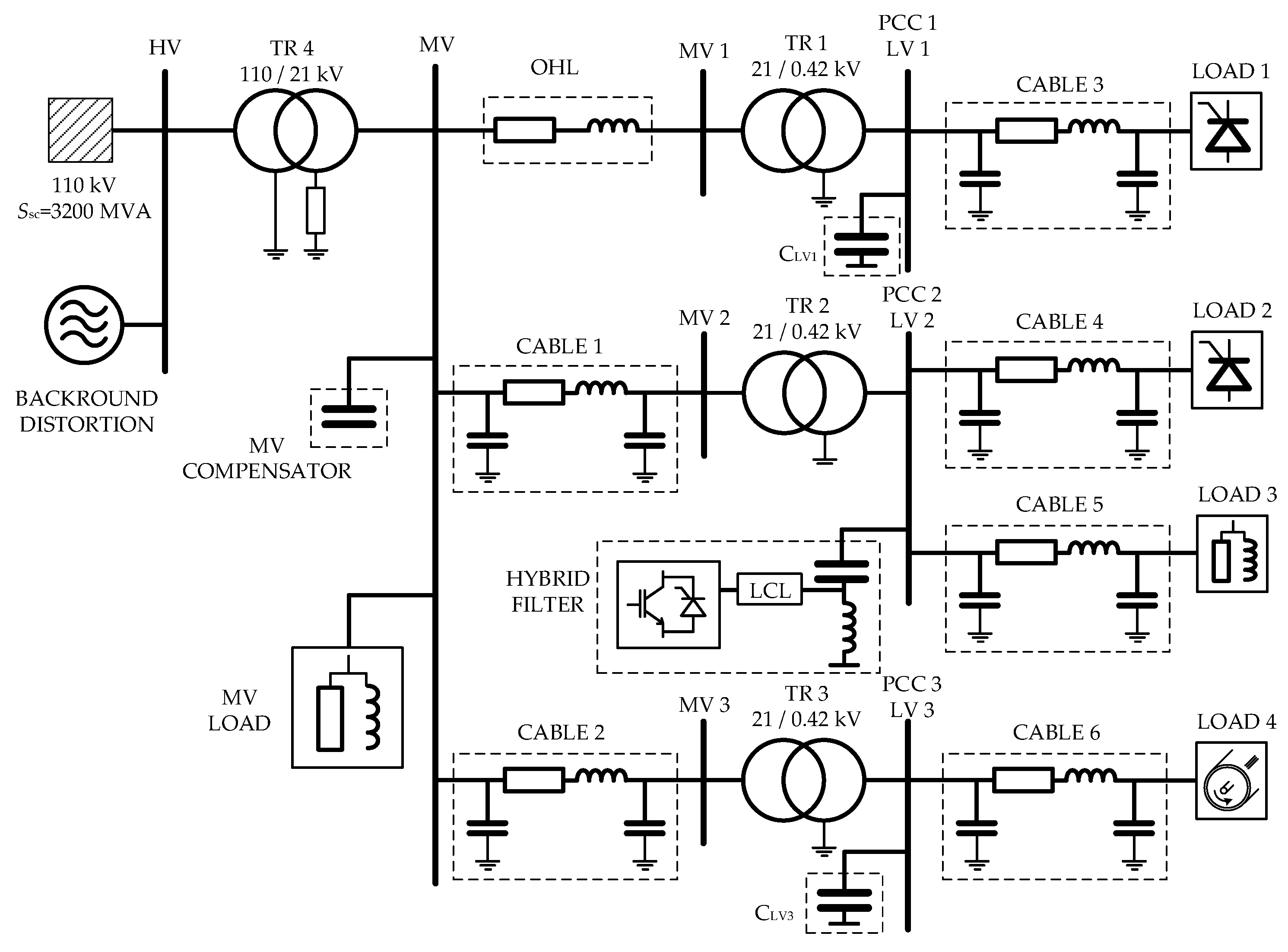
6.1. Introduction to the Test Environment

The medium-voltage benchmark model (MV BNM), specifically designed for harmonic distortion analysis, was used to evaluate the HPF performance. Figure 11 illustrates the MV BNM. The HPF is connected to the Customer 2 location (PCC2) since this customer has an existing passive compensation to which (potentially) the active part can be retrofitted. To avoid resonances with the system, the inductance of the existing passive compensator was adjusted from 0.215 mH to 0.615 mH. Further details of the used model can be found in [36].
The HPF performance was evaluated in two stages. First, the PSCAD software was used, and the HPF was tested within a simulated environment. For this analysis, the MV BNM and the HPF, including the control algorithm, were modeled in PSCAD in detail (as presented in Section 5). Additionally, ideal harmonic sources were utilized to verify the accuracy of the control algorithm in determining the reference. The analysis with ideal harmonic sources is based on the harmonic impedances of the MV BNM.
The second evaluation employs a real-time digital simulator Typhoon HIL in combination with a Digital signal processors (DSPs) development board in the loop. This analysis demonstrates the functional performance of the hybrid filter’s control algorithm, implemented on an actual controller. The purpose of CIL testing is mainly to validate PSCAD simulation results.
It is important to note that the proposed HPF reference calculation method was compared with the conventional control principle, where the filtered harmonics are regulated to zero (ref. 0). The proposed reference calculation method was tested without (ref. imp) and with voltage condition (ref. imp. (volt. cond.)), see Equation (13)).

6.2. PSCAD Simulation Results

The modeled system for the simulations considered only low-order harmonic, namely, the 5th, 7th, 11th, and 13th harmonic components. These harmonic orders are generated in the MV BNM (load 1 and load 2 in Figure 11) by the thyristor rectifier and the background distortion. The simulation results for filtering performance evaluation are presented in Section 6.2.1 (Figure 12, Figure 13 and Figure 14). In Section 6.2.2, the simulation results for assessing the reduction in the required current ratings are presented. Figure 15 shows a comparison of the required average active filter current for the four simulated cases: ref. 0 (blue), ref. imp. (red), ref. imp. (volt. cond., yellow), and without filter (purple). In Figure 16, the numerical results of the comparison of the hybrid filter’s average current are presented.

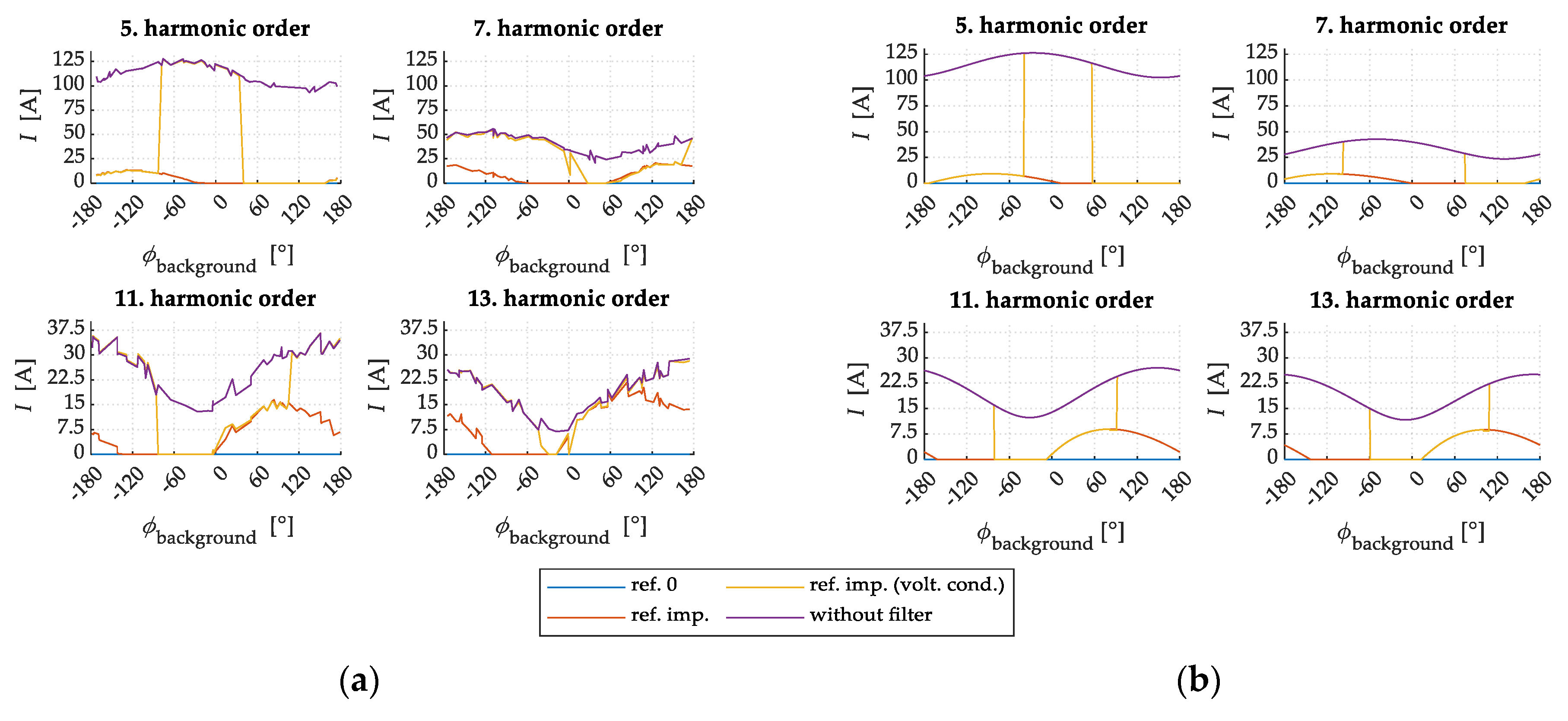
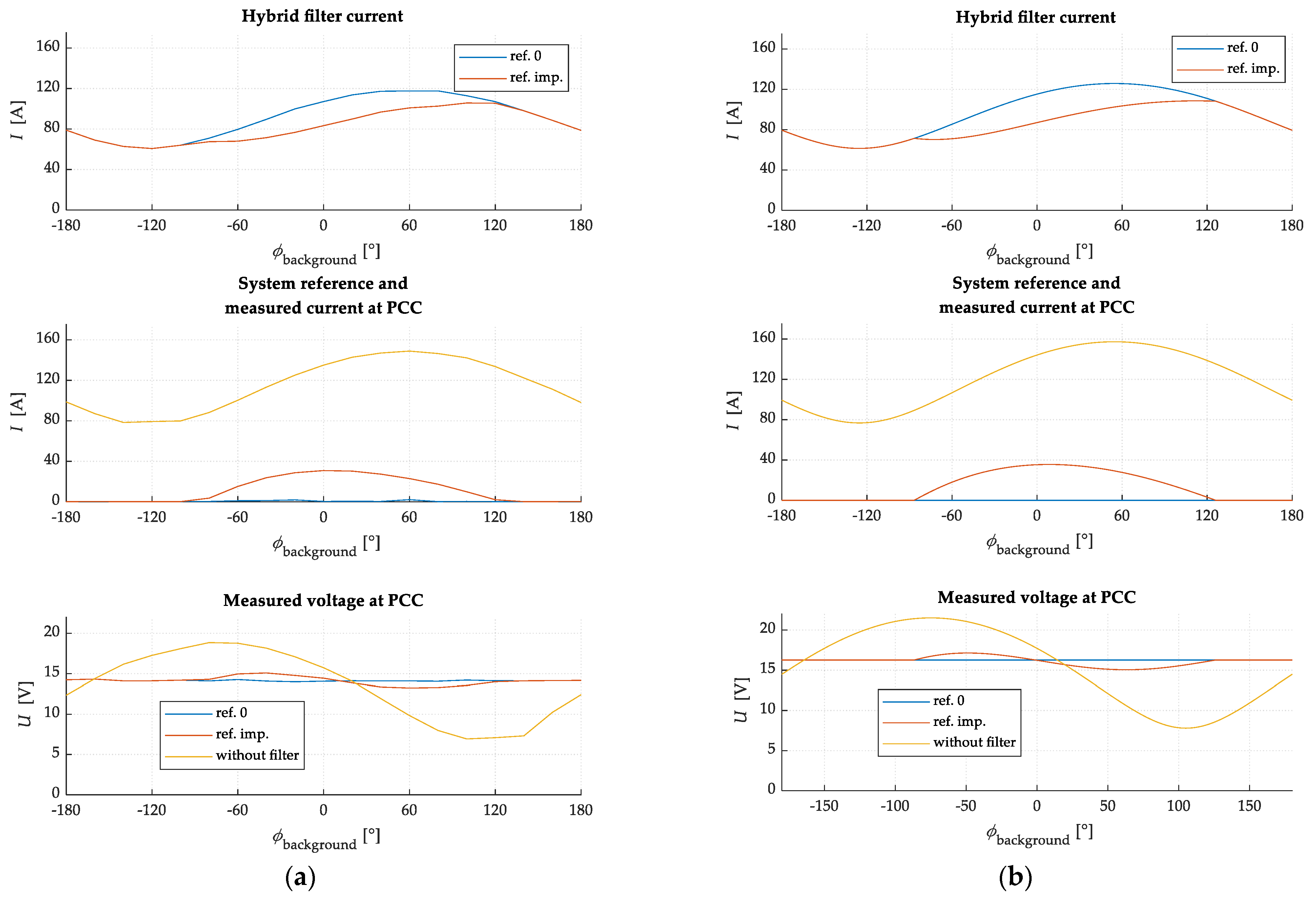
6.2.1. Filtering Performance Evaluation

Figure 12 shows the measured system current IPCC,h, which also represents the control reference. Comparing the current values, it can be seen that the active filter reduces the current harmonic distortion across all observed harmonic components. As expected, the use of the proposed reference (ref. imp.) does not reduce the harmonic distortion to zero at all phase angles of the background distortion. When the voltage condition (Equation (13)) is met (ref. imp. (volt. cond.)), the active filter does not filter the current, and consequently, the current harmonic distortions without the active filter (AF) (purple line) and with the AF (yellow line) are the same.
Figure 13 shows the HPF current, which is (using the proposed reference) reduced at certain angles of background distortion compared to the conventional approach (ref. 0). Greater differences occur at the 11th and 13th harmonic components at positive angles of background distortion. At certain angles of background distortion, the consumer improves voltage harmonic distortion with passive elements, which is also evident from Figure 13.
Figure 14 shows the measured harmonic voltage. As can be seen from the figure, the HPF affects voltage conditions. Voltage harmonic distortion increases at certain phase angles with the use of the HPF in ref. imp. control mode (the purple curve is lower than the red one). If the voltage condition (Equation (13)) is included, the hybrid filter recognizes this, and the current of the active part of the hybrid filter is 0 (yellow curve).

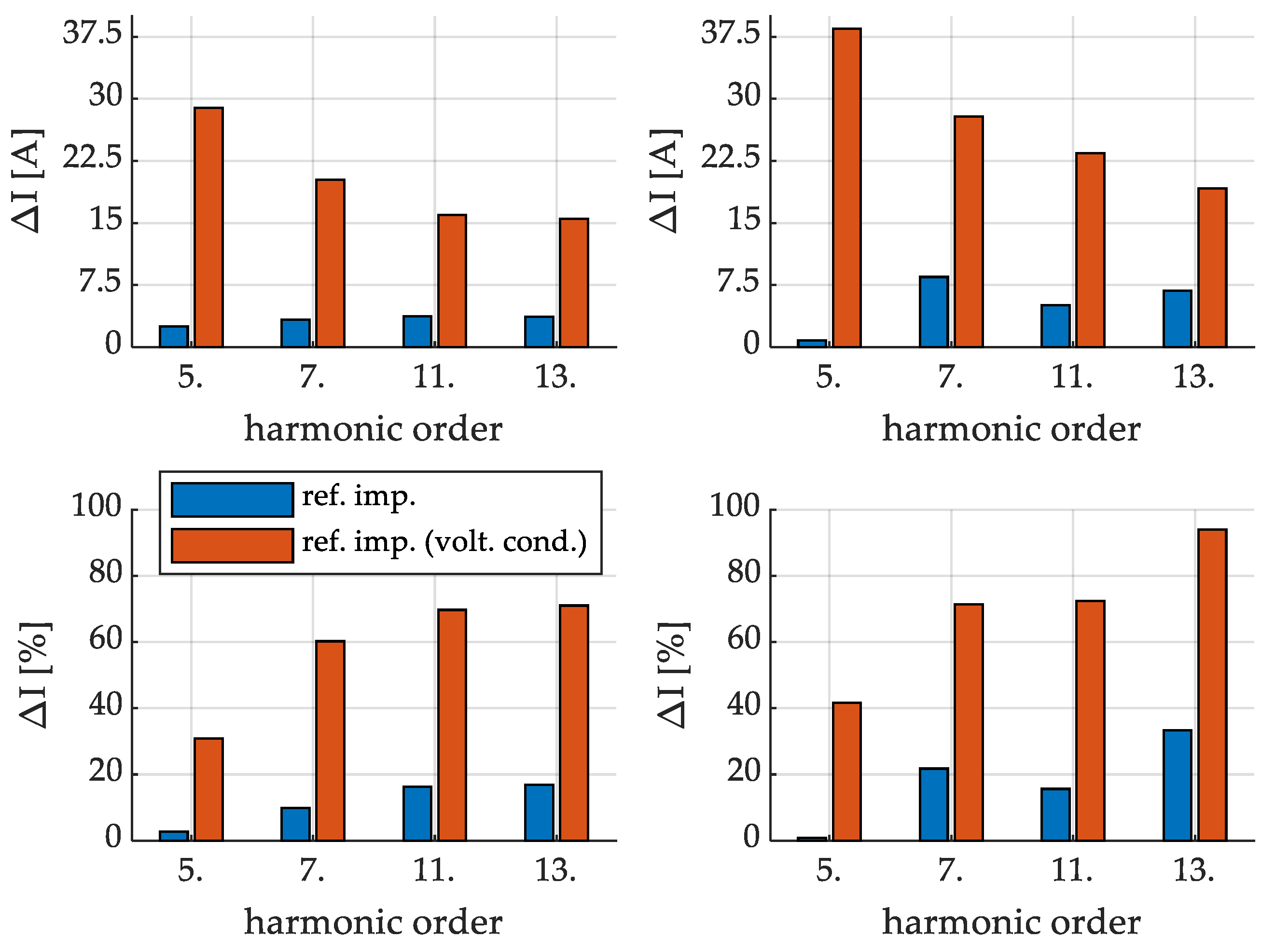
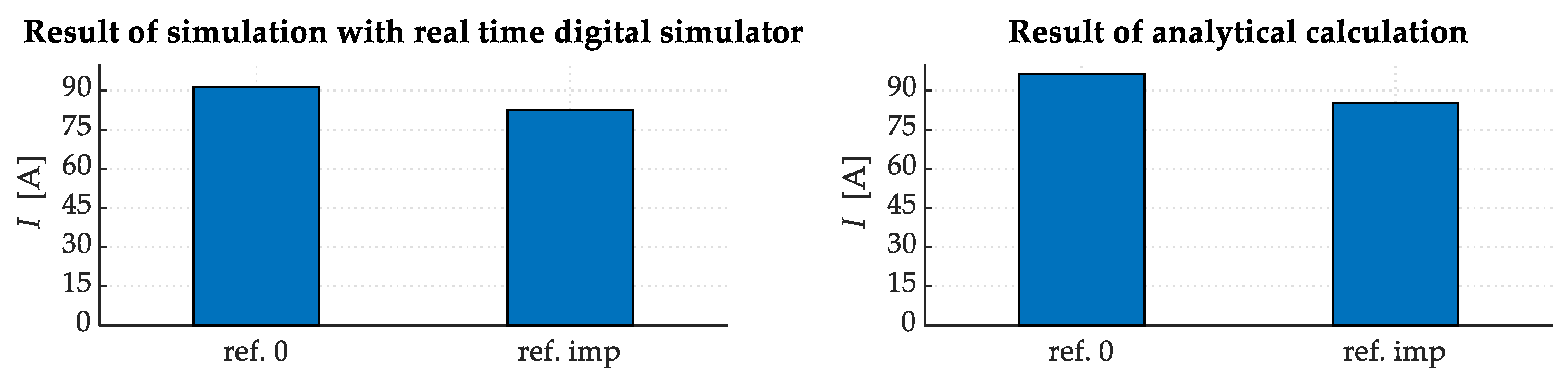
6.2.2. Assessing the Reduction in Required Current Ratings

Figure 15 presents the average harmonic currents that are required for efficient filtering across all background phase angles. The results show that the proposed HPF reference in ref. imp. control mode decreases the hybrid filter’s harmonic current. The reduction becomes even more noticeable when the voltage condition is applied (ref. imp. (volt. cond.)), as this leads to a decrease in voltage harmonic distortion at the PCC. A numerical comparison of these results is also provided in Table 1.
Figure 16 shows simulation and analytical results (absolute and relative values) for differences in the required harmonic HPF current. Two cases are analyzed: the proposed ref. imp. and the ref. imp. with voltage condition. Both simulation results show that using the proposed reference for the hybrid filter (blue color) leads to a decrease in filter currents. The absolute difference remains roughly consistent across all harmonic components, averaging around 5 A. The relative difference varies, as the average harmonic current decreases with higher harmonic orders, ranging from 3% (for the 5th harmonic order) to 20% (for the 13th harmonic order). The reductions in the analytical results exceed that of the simulation, which is expected using an ideal harmonic current source. Please note that the source does not take into account the dynamic nature of the measured harmonic distortion at PCC.
When the voltage condition is applied, the filter current decreases substantially more due to the partial filtering of voltage harmonic distortion by the customer’s passive elements. The reduction in the hybrid filter current ranges from approximately 35% (for the 5th harmonic order) to 70% (for the 13th harmonic order). In terms of absolute values, the reduction amounts to roughly 30 A for the 5th harmonic current, 15 A for both the 11th and 13th harmonic components, and around 20 A for the 7th harmonic component.
A numerical comparison of these results is also provided in Table 2 (absolute values) and Table 3 (relative values).

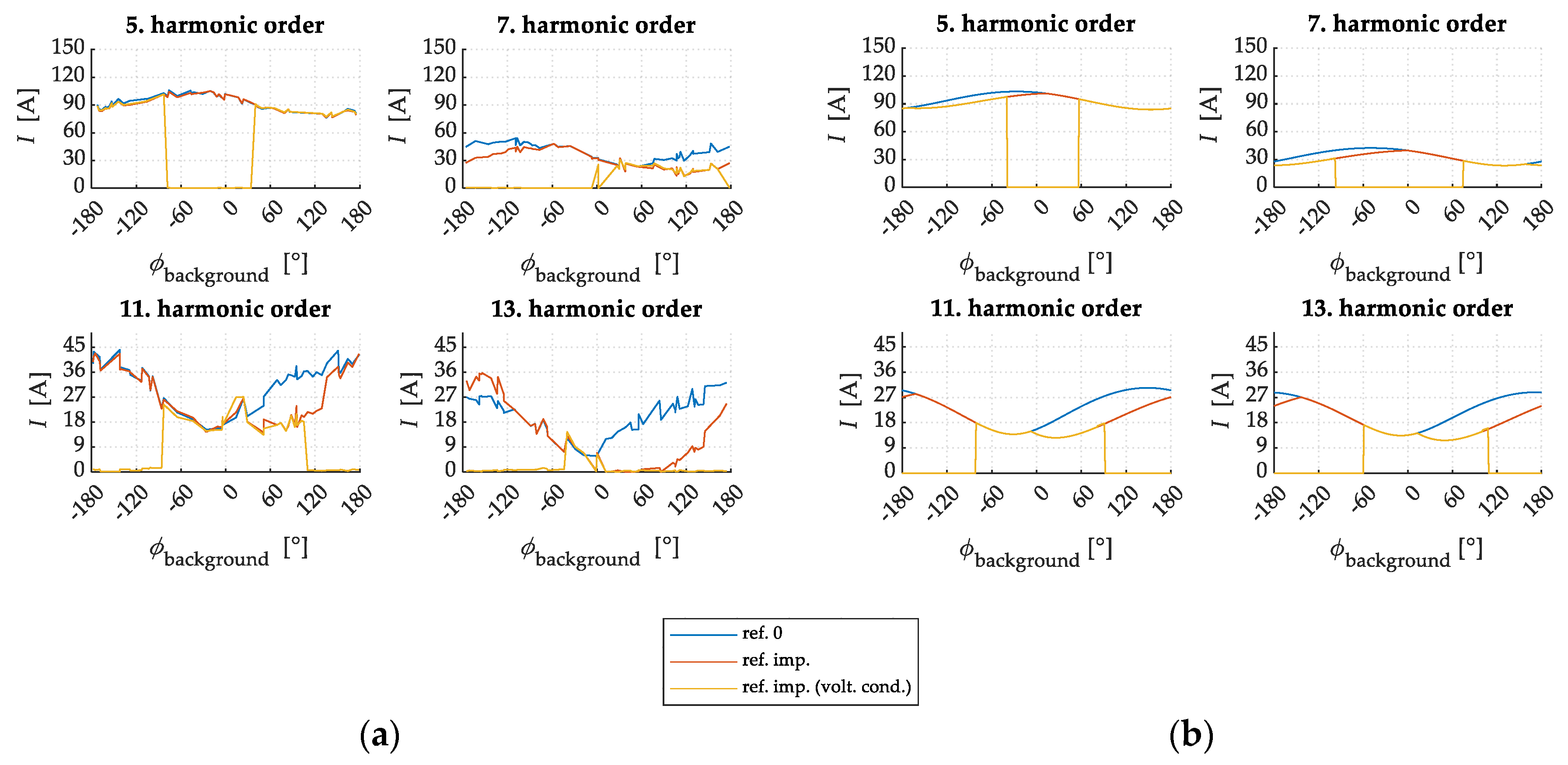
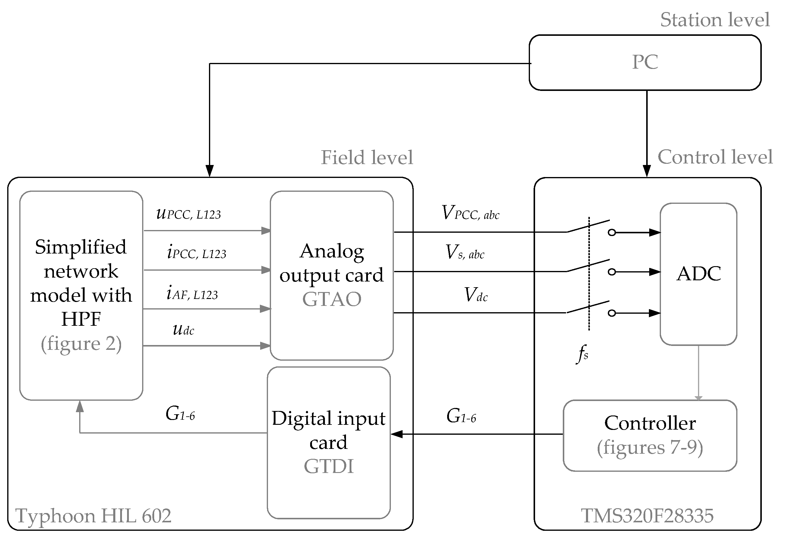
6.3. Controller-in-the-Loop Testing Results

In the second phase of the analysis, the real-time digital simulator Typhoon HIL 604, coupled with a DSP development board (Texas Instruments TMS320F28335), has been used. Due to the simulator’s limitations in handling the full MV BNM model, we opted for a simplified representation. In this model, the network was represented with the short-circuit impedance data from the MV BNM, and the customer was modeled as a passive load and current harmonic source (see Figure 2). The values of individual parameters are presented in Table 4.
Figure 17 illustrates the schematic overview of the testing set-up. Within the Typhoon HIL simulator, a network model with the connected HPF was modeled. The measured quantities required by the controller are fed into the analog output card (GTAO). The output from the simulator is in the form of voltage signals, which are fed into the TMS 320F28335 controller. The TMS hardware converts the input signals and modifies (amplifies) them to correspond to those in the original model. The presented control algorithm (Figure 8) was coded in C language. The controller, in accordance with the presented control algorithm, produces six firing pulses that are fed back to the Typhoon HIL simulator.
It is worth noting that the CIL testing focused only on the fifth harmonic component due to operational constraints with the DSPs.
Figure 18 presents the results for the fifth harmonic component as a comparison between the results obtained through the CIL testing and those obtained analytically using ideal harmonic sources. The harmonic current generated by the active filter is notably reduced within the phase angles of the background distortion spanning from −70° to 120°. This reduction is primarily caused by the fact that the customer is not responsible for all the harmonic distortion at these specific phase angles.
The system reference serves as an indicator of the amount of harmonic current at the PCC and is the same as the measured current when the hybrid filter is operational. If the system reference is not filtered to zero (angles between −70° to 120°), that means the customer is not responsible for that harmonic distortion.
For easier interpretation, Figure 19 provides an overview of the average harmonic current distortion across all background distortion phase angles. The application of the proposed reference leads to a reduction in the harmonic current for 8.9 A when tested with the CIL test set-up and 11 A in analytical calculations. This translates to a relative reduction of 10% in the practical case (utilizing the real-time digital simulator) and 11.5% in the analytical case.
This comparison shows that the proposed reference is correctly calculated in the DSP controller, which mimics the behavior of the proposed control algorithm in a real environment.

7. Conclusions

This paper presents an improved method to calculate the current reference for the controller of an HPF by considering the customer’s harmonic emissions. This advanced approach differs from most of the existing methods where the harmonic distortion is usually filtered to zero. The proposed approach proves to be especially beneficial in networks with high background distortion, such as industrial networks or networks with high shares of CIG. Clearly, in these environments, high harmonic distortions may be a consequence of complex interactions between the customers’ equipment and adjacent devices or just simply caused by harmonic sources elsewhere in the system. By only filtering the customers’ emissions, the required power rating of the active part of the HPF is reduced.
With the use of the proposed hybrid filter topology, the size of the active components can be further reduced, subsequently also reducing the investment and operational costs for the customer.
The method and the topology have been validated using both simulations and controller-in-the-loop testing on a prototype implemented with DSP hardware. These practical tests aligned with the theoretical predictions. Namely, the results indicated a significant decrease in filter current across all harmonics when the voltage condition is used. The simulated reduction varied from 35% to 70%, while the theoretical results showed a slightly broader range of 40% to 90%. Without accounting for the voltage condition, the reductions were more modest, ranging between 3% and 20%. Tests using a real-time digital simulator reaffirmed these findings, consistently showing a 10% reduction in filter current. In terms of absolute values, this translated to reductions of 9 A (simulated) and 11.5 A (calculated). Furthermore, the introduced hybrid filter methodology reduces the need for customers to compensate for all harmonic currents at the PCC.
In line with the ongoing development and research, our involvement with the CIGRE/CIRED JGW C4.42 working group focuses on the continuous assessment of a consumer’s contribution to total harmonic distortion. The primary aim of this group is to suggest methodologies for determining consumer responsibility, a concept we have incorporated and applied to an HPF in this study. The standardization of this approach could enhance the practical application of the methodology discussed in this paper. The final report from the working group is nearing completion and is expected to be published shortly, framing a central aspect of our future research direction.
Furthermore, our future research work will focus on:
Investigating some other control algorithms for the main current control loops of the HPF in combination with the proposed method for current reference calculation. Our initial focus will be on analyzing proportional-resonant (PR) controllers, which promise potential advantages, such as improved selectivity and transient performance, over the PI controllers currently in use.
Extended HIL testing on a real-time simulator, aiming for more accurate modeling of the HPF’s active part, currently modeled as an ideal source. Here, we were faced with equipment limitations that needed to be upgraded. Testing will expand to cover a wider range of harmonic distortions and various network topologies, including real network models and devices (nonlinear loads).
After HIL testing, our attention will move towards the development and laboratory testing of a hardware prototype of the device.

Author Contributions

Conceptualization, L.H. and A.Š.; investigation, L.H.; methodology, L.H. and A.Š.; project administration, A.Š.; software, L.H. and A.Š.; supervision, A.Š.; validation, A.Š.; visualization, L.H.; writing—original draft, L.H.; writing—review and editing, L.H. and A.Š. All authors have read and agreed to the published version of the manuscript.

Funding

This research was funded by the Slovenian Research Agency, research core funding No. L2-3162 (DN-FLEX).

Data Availability Statement

The datasets used and analyzed during the current study are available from the corresponding author on reasonable request.

Conflicts of Interest

The authors declare no conflict of interest.

List of Acronyms

AbbreviationDefinition
ADCAnalog-to-digital converter
AFActive filter
CIGConverter interfaced generation
CILController-in-the-loop
DSPDigital signal processors
GTAOAnalog output card
GTDIDigital input card
HILHardware in the loop
HPF Hybrid power filter
MV BNMMedium-voltage benchmark model
PCPersonal computer
PCCPoint-of-common-coupling
PIProportional integral
THDTotal harmonic distortion

References

  1. EN 50160; Voltage Characteristics of Electricity Supplied by Public Distribution Systems. IEC: Geneva, Switzerland, 2011.
  2. Padmanaban, S.; Sharmeela, C.; Holm-Nielsen, J.B.; Sivaraman, P. Power Quality in Modern Power Systems, 1st ed.; Elsevier: Amsterdam, The Netherlands, 2020. [Google Scholar]
  3. Bollen, M.H.J. Introduction to Power Quality. In Understanding Power Quality Problems: Voltage Sags and Interruptions; Wiley-IEEE Press: New York, NY, USA, 2000. [Google Scholar]
  4. Hernández-Mayoral, E.; Madrigal-Martínez, M.; Mina-Antonio, J.D.; Iracheta-Cortez, R.; Enríquez-Santiago, J.A.; Rodríguez-Rive, O.; Martínez-Reyes, G.; Mendoza-Santos, E. A Comprehensive Review on Power-Quality Issues, Optimization Techniques, and Control Strategies of Microgrid Based on Renewable Energy Sources. Sustainability 2023, 15, 9847. [Google Scholar] [CrossRef]
  5. Lee, T.-L.; Wang, Y.-C.; Li, J.-C.; Guerrero, J.M. Hybrid active filter with variable conductance for harmonic resonance suppression in industrial power systems. IEEE Trans. Ind. Electron. 2014, 62, 746–756. [Google Scholar] [CrossRef]
  6. Xue, G.; Chen, B.; Tian, C.; Yuan, J.; Zhou, Y.; Chen, G.; Luo, Y.; Chen, Y. A Novel Hybrid Active Power Filter with Multi-Coupled Coils. Electronics 2021, 10, 998. [Google Scholar] [CrossRef]
  7. Alasali, F.; Nusair, K.; Foudeh, H.; Holderbaum, W.; Vinayagam, A.; Aziz, A. Modern Optimal Controllers for Hybrid Active Power Filter to Minimize Harmonic Distortion. Electronics 2022, 11, 1453. [Google Scholar] [CrossRef]
  8. Dash, D.K.; Sadhu, P.K. A Review on the Use of Active Power Filter for Grid-Connected Renewable Energy Conversion Systems. Processes 2023, 11, 1467. [Google Scholar] [CrossRef]
  9. Fujita, H.; Akagi, H. A practical approach to harmonic compensation in power systems-series connection of passive and active filters. IEEE Trans. Ind. Appl. 1991, 27, 1020–1025. [Google Scholar] [CrossRef]
  10. Bhattacharya, S.; Cheng, P.-T.; Divan, D.M. Hybrid Solutions for Improving Passive Filter Performance in High Power Applications. IEEE Trans. Ind. Appl. 1997, 33, 3. [Google Scholar] [CrossRef]
  11. Singh, B.; Verma, V. An Indirect Current Control of Hybrid Power Filter for Varying Loads. IEEE Trans. Power Deliv. 2005, 21, 178–184. [Google Scholar] [CrossRef]
  12. Inzunza, R.; Akagi, H. A 6.6-kV Transformerless Shunt Hybrid Active Filter for Installation on a Power Distribution System. IEEE Trans. Power Electron. 2005, 20, 893–900. [Google Scholar] [CrossRef]
  13. Peng, F.; Akagi, H.; Nabae, A. A New Approach to Harmonic Compensation in Power Systems-A Combined System of Shunt Passive and Series Active Filters. IEEE Trans. Ind. Appl. 1990, 26, 983–990. [Google Scholar] [CrossRef]
  14. Chen, Z.; Blaabjerg, F.; Pedersen, J. Hybrid Compensation Arrangement in Dispersed Generation Systems. IEEE Trans. Power Deliv. 2005, 20, 1719–1727. [Google Scholar] [CrossRef]
  15. Corasaniti, V.F.; Barbieri, M.B.; Arnera, P.L.; Valla, M.I. Hybrid Active Filter for Reactive and Harmonics Compensation in a Distribution Network. IEEE Trans. Ind. Electron. 2009, 56, 670–677. [Google Scholar] [CrossRef]
  16. Chen, L.; Xie, Y.; Zhang, Z. Comparison of Hybrid Active Power Filter topologies and principles. In Proceedings of the International Conference on Electrical Machines and Systems, Wuhan, China, 17–20 October 2008. [Google Scholar]
  17. Shuai, Z.; Luo, A.; Zhu, W.; Fan, R.; Zhou, K. Study on a Novel Hybrid Active Power Filter Applied to a High-Voltage Grid. IEEE Trans. Power Deliv. 2009, 24, 2344–2352. [Google Scholar] [CrossRef]
  18. Luo, A.; Tang, C.; Shuai, Z.K.; Zhao, W.; Rong, F.; Zhou, K. A Novel Three-Phase Hybrid Active Power Filter with a Series Resonance Circuit Tuned at the Fundamental Frequency. IEEE Trans. Ind. Electron. 2009, 56, 2431–2440. [Google Scholar] [CrossRef]
  19. Srianthumrong, S.; Jintagosonwit, P. Implementation and Performance of an Anti-Resonance Hybrid Delta-Connected Capacitor Bank for Power Factor Correction. IEEE Trans. Power Electron. 2007, 22, 2543–2551. [Google Scholar] [CrossRef]
  20. Herman, L.; Papic, I.; Blazic, B. Comparison of circuit configuration and filtering performance between parallel and series hybrid active filter. In Proceedings of the 22nd International Conference and Exhibition on Electricity Distribution (CIRED 2013), Stockholm, Sweden, 10–13 June 2013. [Google Scholar]
  21. Akagi, H. Trends in Active Power Line Conditioners. IEEE Trans. Power Electron. 1994, 9, 263–268. [Google Scholar] [CrossRef]
  22. Sung, J.H.; Park, S.; Nam, K. New Hybrid Parallel Active Filter Configuration Minimizing Active Filter Size. IEE Proc. Electr. Power Appl 2006, 147, 93–98. [Google Scholar] [CrossRef]
  23. Teodorescu, R.; Blaabjerg, F.; Liserre, M.; Loh, P.C. Proportional-resonant controllers and filters for grid-connected voltage-source converters. IET Proc. Electr. Power Appl. 2006, 153, 750–762. [Google Scholar] [CrossRef]
  24. Lascu, C.; Asiminoaei, L.; Boldea, I.; Blaabjerg, F. High Performance Current Controller for Selective Harmonic Compensation in Active Power Filters. IEEE Trans. Power Electron. 2007, 22, 1826–1835. [Google Scholar] [CrossRef]
  25. Bojoi, R.; Griva, G.; Bostan, V.; Guerriero, M.; Farina, F.; Profumo, F. Current Control Strategy for Power Conditioners Using Sinusoidal Signal Integrators in Synchronous Reference Frame. IEEE Trans. Power Electron. 2005, 20, 1402–1412. [Google Scholar] [CrossRef]
  26. Liserre, M.; Teodorescu, R.; Blaabjerg, F. Multiple Harmonics Control for Three-Phase Grid Converter Systems with the Use of PI-RES Current Controller in a Rotating Frame. IEEE Trans. Power Electron. 2006, 21, 836–841. [Google Scholar] [CrossRef]
  27. Bojoi, R.; Limongi, L.R.; Roiu, D.; Tenconi, A. Frequency-domain analysis of resonant current controllers for active power conditioners. In Proceedings of the IECON 2008—34th Annual Conference of IEEE Industrial Electronics Society, Orlando, FL, USA, 10–13 November 2008; pp. 3141–3148. [Google Scholar]
  28. Yepes, A.G.; Freijedo, F.D.; Doval-Gandoy, J.; López, Ó.; Malvar, J.; Fernandez-Comesaña, P. Effects of discretization methods on the performance of resonant controllers. IEEE Trans. Power Electron. 2010, 25, 1692–1712. [Google Scholar] [CrossRef]
  29. Miret, J.; Castilla, M.; Matas, J.; Guerrero, J.M.; Vasquez, J.C. Selective Harmonic-Compensation Control for Single-Phase Active Power Filter With High Harmonic Rejection. IEEE Trans. Ind. Electron. 2009, 56, 3117–3127. [Google Scholar] [CrossRef]
  30. Božiček, A.; Papič, I.; Blažič, B. Performance evaluation of the DSP-based improved time-optimal current controller for STAT-COM. Int. J. Electr. Power Energy Syst. 2017, 91, 209–221. [Google Scholar] [CrossRef]
  31. Herman, L.; Božiček, A.; Blažič, B.; Papič, I. Real-time simulations of a parallel hybrid active filter with hardware-in-the-loop. In Proceedings of the 2014 16th International Conference on Harmonics and Quality of Power (ICHQP), Bucharest, Romania, 25–28 May 2014; pp. 576–580. [Google Scholar]
  32. Bozicek, A.; Blazic, B.; Papic, I. Time-optimal operation of a predictive current controller for voltage source converters. In Proceedings of the 2011 International Conference on Power Engineering, Energy and Electrical Drives (POWERENG), Malaga, Spain, 11–13 May 2011; pp. 1–7. [Google Scholar]
  33. Špelko, A.; Blažič, B.; Papič, I.; Herman, L. Active Filter Reference Calculations Based on Customers’ Current Harmonic Emissions. Energies 2021, 14, 220. [Google Scholar] [CrossRef]
  34. Pfajfar, T.; Blazic, B.; Papic, I. Harmonic Contributions Evaluation with the Harmonic Current Vector Method. IEEE Trans. Power Deliv. 2007, 23, 425–433. [Google Scholar] [CrossRef]
  35. Spelko, A.; Blazic, B.; Papic, I.; Pourarab, M.; Meyer, J.; Xu, X.; Djokic, S.Z. CIGRE/CIRED JWG C4.42: Overview of common methods for assessment of harmonic contribution from customer installation. In Proceedings of the 2017 IEEE Manchester PowerTech, Manchester, UK, 1–22 June 2017; pp. 1–6. [Google Scholar]
  36. Papic, I.; Matvoz, D.; Spelko, A.; Xu, W.; Wang, Y.; Mueller, D.; Miller, C.; Ribeiro, P.F.; Langella, R.; Testa, A. A Benchmark Test System to Evaluate Methods of Harmonic Contribution Determination. IEEE Trans. Power Deliv. 2018, 34, 23–31. [Google Scholar] [CrossRef]
Figure 1. The diagram of the proposed topology of HPF.
Energies 16 07876 g001
Figure 2. Single-line (equivalent) diagram of the proposed topology.
Energies 16 07876 g002
Figure 3. The required power of the active part of the hybrid filter as a function of the tuning frequency of the passive part [20]—case parameters (in p.u.): Usupply,1 = 1; ILoad,1 = 1; ILoad,5 = 0.2; ILoad,7 = 0.14; ft = 200 Hz.
Energies 16 07876 g003
Figure 4. Representation of theoretically minimal required ratings of voltage converters for the most commonly used topologies [20]—case parameters (in p.u.): Usupply,1 = 1; ILoad,1 = 1; ILoad,5 = 0.2; ILoad,7 = 0.14; ft = 200 Hz.
Energies 16 07876 g004
Figure 5. Equivalent network of the single-line model used for defining reference harmonic impedances, utilizing fictive voltages and currents.
Energies 16 07876 g005
Figure 6. Phasor diagram: (a) before the HPF starts with the operation; (b) ideal case; (c) realistic case.
Energies 16 07876 g006
Figure 7. Flowchart for reference current calculation method.
Energies 16 07876 g007
Figure 8. Control block diagram of the HPF.
Energies 16 07876 g008
Figure 9. Block Diagram of the Reference Control Loop [34].
Energies 16 07876 g009
Figure 10. Current control block diagram [34].
Energies 16 07876 g010
Figure 11. MV benchmark model scheme [36].
Energies 16 07876 g011
Figure 12. Measured system current (reference) at PCC: PSCAD results (a) vs. ideal harmonic sources analysis (b).
Energies 16 07876 g012
Figure 13. Hybrid filter current: PSCAD simulation (a) and analysis with ideal harmonic sources (b).
Energies 16 07876 g013
Figure 14. Measured harmonic voltage distortion at PCC: PSCAD results (a) compared to the ideal harmonic source analysis (b).
Energies 16 07876 g014
Figure 15. Comparison of the hybrid filter’s average current.
Energies 16 07876 g015
Figure 16. Differences in the average HPF current: simulation results (left) and analytical calculation (right).
Energies 16 07876 g016
Figure 17. Scheme of hardware connections between control hardware and Typhoon HIL.
Energies 16 07876 g017
Figure 18. Result of CIL analysis with Typhoon HIL simulator (a) and ideal harmonic source (b).
Energies 16 07876 g018
Figure 19. Comparison of the average current of the hybrid filter in the simulation.
Energies 16 07876 g019
Table 1. Numerical results of the comparison of the HPF’s average current.
Harm. Comp.Results of SimulationResults of Analytical Calculation
Ref. 0Ref. Imp.Ref. Imp. (Volt. Cond.)Ref. 0Ref. Imp.Ref. Imp. (Volt. Cond.)
5th92.34915353.8593.8391.3164.93
7th39.0430.5511.1633.5730.2713.35
11th32.3927.338.9522.9319.206.95
13th20.4313.631.2321.8418.166.33
Table 2. Numerical results (absolute values) of the differences in the average HPF current: simulation results and analytical calculation.
Harm. Comp.Results of SimulationResults of Analytical Calculation
Ref. Imp.Ref. Imp.
(Volt. Cond.)
Ref. Imp.Ref. Imp. (Volt. Cond.)
5th2.52 A28.90 A0.80 A38.48 A
7th3.30 A20.22 A8.48 A27.88 A
11th3.73 A15.96 A5.06 A23.44 A
13th3.68 A15.51 A6.80 A19.20 A
Table 3. Numerical results (relative values) of the differences in the average HPF current: simulation results and analytical calculation.
Harm. Comp.Results of SimulationResults of Analytical Calculation
Ref. Imp.Ref. Imp.
(Volt. Cond.)
Ref. Imp.Ref. Imp. (Volt. Cond.)
5th2.69%30.80%0.87%41.68%
7th9.83%60.23%21.73%71.41%
11th16.26%69.69%15.63%72.37%
13th16.84%71.02%33.30%94.00%
Table 4. Parameters of the simplified MV BNM model.
Grid ImpedanceHPF Passive ComponentsEquivalent LoadLCL-Filter
R g r i d = 0.0004   R C = 0.00405   I l o a d , 5 = 91.84   A L L C L , 1 = 1.1   m H
L g r i d = 0.0372   m H L C = 0.615   m H
C C = 2358   μ F
φ l o a d , 5 = 162 ° L L C L , 2 = 0.4   m H
R l o a d = 0.45   R L C L , 1 = 0.5  
L l o a d = 3.8   m H R L C L , 2 = 0.1  
R L C L = 0.2  
C L C L = 10   µ F
Disclaimer/Publisher’s Note: The statements, opinions and data contained in all publications are solely those of the individual author(s) and contributor(s) and not of MDPI and/or the editor(s). MDPI and/or the editor(s) disclaim responsibility for any injury to people or property resulting from any ideas, methods, instructions or products referred to in the content.

