1. Introduction
To mitigate climate change by 2030, renewable energies have been increasing in markets such as power generation, heating and cooling, and transport. The production of renewable energy from photovoltaic, wind, and hydropower systems has notably increased. One of the most viable options to produce this type of energy is large-scale wind systems; however, they have disadvantages such as space availability, the impact on the utility network, public acceptance, and transmission and distribution losses. An alternative that reduces some of these drawbacks is using small wind turbines [
1]. Although the study of small wind turbines began in the 1970s, they have now gained popularity. They are presented as a viable option for the sustainable energy development of new buildings in urban environments [
2]. Another reliable, sustainable, and economical technology contributing to climate change mitigation is microgrids (µGs), defined as a low-voltage distribution network in which renewable energy sources and loads are interconnected through power electronic converters (PECs). There are different types of µGs depending on the current type and operating modes they handle. However, DC µGs (DCµGs) present advantages in aspects such as efficiency, size, investment, and operating costs [
3,
4]. On the other hand, although photovoltaic systems are the more common distributed energy resources used in µGs, wind power has also been used extensively [
5]. At the same time, photovoltaic, wind, and biomass are the renewable resources with the fastest-growing usage recently since they are ecological, simple to deploy, and highly developed [
6]. Several examples of the use of wind energy in µGs can be found in the literature. The authors of [
7] present a methodology for sizing a battery energy storage system for a µG feed by a wind system. The energy storage system is sized using wind speed measurements over a year. In [
8], a comparison between a battery energy storage system and a superconducting magnetic energy storage system is presented; both systems are controlled using fuzzy logic. These energy storage systems aim to improve the stability and quality of the energy in a DCµG feed by a photovoltaic system and a wind system. In [
9], the implementation of a controller applied to a DCµG feed by a wind system, including a doubly fed induction generator, is described. In [
10], a case study is presented in which the authors implement a PI controller for a hybrid insolated µG; the energy sources of this µG are biomass, solar photovoltaic, and wind. In [
11], an energy management strategy for a grid-connected µG is presented; the primary renewable energy source of this µG is a wind turbine.
Wind speed is variable by nature; therefore, wind systems are designed to operate between lower and upper-speed limits, called cut-in and cut-out speeds. A control system is required to manage these speed limits and extract the greatest amount of energy from the wind, making the wind system more efficient. Between the cut-in and cut-out speeds, the control system performs different tasks. If the system has not reached its maximum allowable power (partial load region), the control performs the task of maximum power point tracking (MPPT). On the other hand, if the system reaches its maximum power (full-load region), the control increases the rotational resistance of the turbine, limiting its angular velocity and extracted power [
12,
13]. Due to the importance of the MPPT algorithm in increasing the usage of renewable energy resources and system efficiency, recent research is being conducted in this field. In [
14], an adaptative optimal fuzzy controller for the MPPT in a wind system based on reinforcement learning is described. The wind system in this research uses a permanent magnet synchronous generator (PMSG). In [
15], an MPPT controller was implemented in a grid-connected wind system. The algorithm implemented considers the wind speed, a unified model of the wind system, and energy conversion losses to extract the maximum power available and inject it into the utility grid. In [
16], a controller for the MPPT applied to a PMSG-based small-scale wind system connected to a DC-Bus is presented. The energy conversion system comprises an uncontrolled rectifier connected in series with a DC/DC boost PEC. Similarly, in [
17], the implementation of a robust controller for the MPPT applied to a grid-connected PMSG-based wind system is described. The control in this work is based on a high-gain perturbation observer-based nonlinear adaptive control. Finally, in [
18], an MPPT algorithm applied to a wind system with a doubly fed induction generator is presented; in this case, the MPPT is achieved with searching space minimization-based particle swarm optimization.
Testing the MPPT control algorithms, the PECs, and other elements of a wind system in real-time on a physical system may be unfeasible due to the space required, the cost that this entails, and the discontinuity in the wind. These limitations can be reduced with an emulator [
19]. An alternative to emulating physical systems, which allows validating their control systems and is widely used in energy systems, is real-time hardware in the loop (HIL) simulation [
20]. If the power elements that make up a system are emulated while their controller or a part of it is embedded, the real-time HIL simulation is classified as a Controller-HIL (C-HIL) [
21]. With real-time C-HIL simulation, testing real controllers with algorithms and parameters like those used in the field is feasible. Also, the C-HIL provides a wide range of operating conditions at the experimental stage without the risk of damaging actual equipment [
22]. Currently, HIL simulation is essential in the system life cycle, in processes from design to implementation. HIL simulation is applied in aerospace, automotive, marine, defense, robotics, and energy fields. In these fields, the HIL simulation provides benefits like flexibility, safety, rapid prototyping, cost-effectiveness, credibility, and simulation speed [
20]. Due to the importance of the HIL, several recent research studies integrate this topic; for example, some of them are presented next. In [
23], a self-adaptative control method based on a digital twin is presented. The control is applied to a heating, ventilation, and air-conditioned system that is a MIMO system. The digital twin is developed by integrating HIL and software in the loop. In [
24], the testing of the flight software of a CubeSat is presented. The satellite studied is a MOVE-II CubeSat (Technical University of Munich, Munich, Germany), and the HIL allows testing it on-ground in a simulated space environment. The HIL simulation replaces the satellite sensors and actuators. Finally, in [
25], an automatic test system for the autopilot of an unnamed aerial vehicle is presented. For this purpose, a unified model for different types of aerial vehicles is deployed and implemented in an FPGA-based HIL platform.
Also, several works in the literature report using HIL simulation in energy conversion systems. In [
26], an HIL system was developed using NI technology to study MPPT in a wind generation system. The HIL system was implemented with NI PXI platform (NATIONAL INSTRUMENTS CORP., Austin, TX, USA) based on LabVEW (Available on:
https://www.ni.com/es/shop/labview.html, Accessed 17 November 2023) The implemented wind system consists of a turbine with a gearbox, a non-controllable rectifier, and a DC-boost converter connected in series. In [
27], an HIL platform is presented to validate an optimal control strategy. The platform was developed in a real-time digital simulator (RTDS) and includes a turbine with a gearbox and variable pitch angle, a PMSG, a PEC AC/DC, and a PEC DC/AC. This paper does not detail the RTDS used to implement the model in hardware. In [
28], an HIL simulation to evaluate the dynamic response of a floating wind turbine is described. The HIL platform is composed of a wind turbine of 15 MW scaled by a factor of 1:1000, a wind tunnel, and a six-degree freedom robotic base that emulates the wave movement. In [
29], a wind power generation system model for operating a modular multi-level converter in an HIL simulation is proposed. The model was developed in MATLAB/Simulink (Availabe on:
https://la.mathworks.com/products/matlab.html, Accessed 17 November 2023) and implemented on an HIL OP4510 platform (OPAL-RT TECHNOLOGIES, Montreal, Canada). In [
12], an HIL simulator was implemented to evaluate wind turbines’ pitch angle control system. The simulator is divided into two parts: an emulator reproducing the wind energy conversion system (wind speed, aerodynamics, drive train, and generator) and a digital hydraulic pitch system (hydraulic motor, flow sensor, valves, etc.). The wind energy conversion system model was implemented in MATLAB/Simulink (Availabe on:
https://la.mathworks.com/products/matlab.html, Accessed 17 November 2023) and communicates with the digital hydraulic pitch system via NI-Veristand. In [
30], a nonlinear integral backstepping controller for the load frequency control in a µG is presented. The µG in this research includes, among others, a wind generator. The controller is validated with an OPAL-RT (OPAL-RT TECHNOLOGIES, Montreal, Canada), showing to be efficient for frequency regulation. HIL simulation is also used in this kind of system in topics related to cybersecurity. In [
31], experimental validation of remedial action against false data injection cyberattacks in a µG fed by wind and photovoltaic energy is presented. The security mechanism includes the detection of false data injection using artificial intelligence and reacts to keep the functionality of the µG. The mechanism was proven over an HIL testbed. In [
32], the detection of false data injection cyberattacks targeting a lab-scale microgrid is performed. The detection is deployed using a recurrent neural network and is proven in an HIL testbed in which the cyberattack and the detection are implemented in an OP4510 HIL simulator. Finally, in [
33], the development of an HIL testbed for studying cyberattacks over a µG is described. The µG is lab-scale and includes wind and photovoltaic power generators. The HIL setup includes the lab-scale µG, an OPAL-RT platform, data acquisition units, and controllers.
Despite the advantages that HIL simulation provides, its cost represents a drawback. Hence, recently, researchers have developed HIL platforms using low-cost hardware like digital signal processors, graphic processing units, and FPGAs [
34]. In [
35], a floating-point format is designed for FPGA applications. This new format’s resource usage is validated by implementing an HIL PEC emulator in a Xilinx FPGA Zynq 7 (Advanced Micro Devices, Inc., Santa Clara, USA). In [
36], a low-cost HIL for real-time simulation of electric machines and electric drives is presented. The platform includes a TMS28379D DSP (Texas Instruments Incorporated, Dallas, USA) that emulates an electric machine and its drive and a TMS28377S DSP (Texas Instruments Incorporated, Dallas, USA) that runs the controller. The platform was evaluated by controlling a DC machine with a chopper and a three-phase induction machine with a full-bridge inverter. In [
37], an open-source, low-cost HIL simulation platform for testing control strategies for artificial pancreas research is presented. The platform comprises two Arduino UNO boards, with one reproducing the Bergman’s minimal model. In [
38], a power-sharing control in a grid-tied DC microgrid using an HIL platform is presented. The platform was developed in an NI myRIO 1900 (NATIONAL INSTRUMENTS CORP., Austin, USA) and exhibits relative errors below 2%. Finally, in [
39], a testbed to validate a residential photovoltaic system is presented. The testbed includes, among other components, an HIL platform developed in an NI myRIO that emulates a system composed of a photovoltaic array, a boost converter, and a monophasic inverter. Although these alternatives have the advantage of being low-cost, the specific language used in these applications and the high technical level at which these implementations are reported can make their reproduction difficult for non-expert researchers. In this case, graphical language facilitates the implementation of FPGA applications, helping non-expert users deploy these applications efficiently [
34].
This article describes the implementation of an HIL platform (following the C-HIL approach) in a NI myRIO 1900 to evaluate the performance of controllers applied to a small wind system (SWS) that functions as a distributed generator for a DCµG. The platform reproduces the dynamic response of a wind system with an integration time of 10 µs. This wind system comprises a 3.5 kW turbine with a fixed blade pitch angle, no gear transmission, a PMSG, and a full three-phase H-bridge AC/DC power electronic converter. It includes a control algorithm based on the wind speed measurement, implemented in a separate loop of the wind system model, allowing for its modification without altering the wind system. Implementing this platform on relatively limited hardware is not trivial and represents a valuable contribution. In the case of the SWS, its implementation implies nonlinear behaviors and, therefore, nonlinear equations. This paper shows how to do it by distributing the computational work, using a high-level description language, and achieving good accuracy and latency with a student development kit. The main contributions of this article are summarized below:
Description of the development of an HIL platform that serves as a research infrastructure in the field of control algorithms for wind systems.
Description of developing an HIL platform with low-cost hardware compared to commercial HIL platforms and using dedicated real-time platforms.
Implementing a platform in a student development kit using LabVIEW makes it more accessible for reproduction, considering the cost of the hardware and the fact that it is programmed using a high-level graphical language.
The wind system and its controller are embedded in different loops, allowing the control system to be modified to validate different algorithms without the need to modify the wind system’s model or include new hardware.
The nonlinear behaviors of the wind system model and its control algorithm are embedded using look-up tables or in a different instance of the FPGA, allowing the model to be solved with high latency using relatively limited hardware.
The article is organized into six sections.
Section 1 corresponds to the introduction;
Section 2 describes the wind system and its model;
Section 3 describes the control algorithm applied to the wind system;
Section 4 describes the implementation of the HIL platform;
Section 5 describes the results; and
Section 6 describes the conclusions.
2. Wind System Description and Modeling
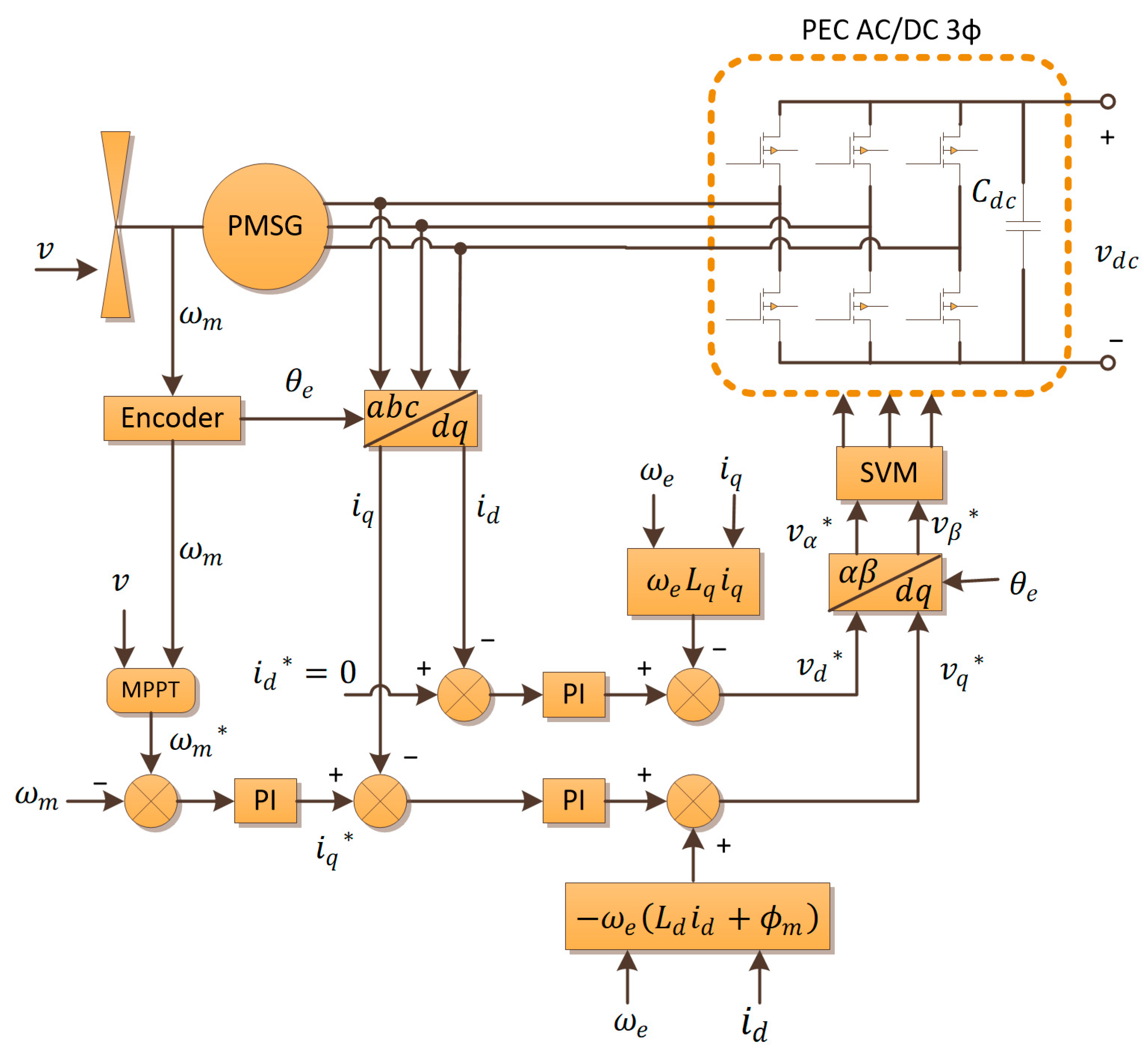
The wind system studied in this research is of the small wind type, with a maximum generation capacity of 3.5 kW. It features a turbine with a fixed blade pitch angle and does not include a speed reduction system with gears. Instead, it utilizes a PMSG, and the rotation speed of the blades is controlled by manipulating the stator current through a full three-phase H-bridge AC/DC CEP. Therefore, the CEP has two functions: transferring the generated energy and controlling the rotation speed of the blades to extract the maximum possible power. In
Figure 1, the diagram of the wind system that was studied is shown [
40]. In this Figure, variables denoted with * are set-point values.
In Equation (1) [
40], the power of the wind
is determined based on its density
, speed
, and the area described by the wind turbine when rotating
.
The mechanical power
generated from the wind power depends on the power coefficient
as shown in Equation (2) [
40].
In turn, the power coefficient depends on the speed ratio (TSR)
and the angle of attack of the blades
expressed in degrees. The TSR is defined in Equation (3), where
is the angular speed of the wind turbine, and
is its radius. This variable represents a ratio between the tangential speed at the extreme of the blades and the wind speed.
The dependency of the power factor with
and
is expressed in Equation (4). At the same time, Equation (4) depends on the ratio
, which is a
dependent function. Coefficients in Equations (4) and (5) are characteristics of the wind turbine and, for this research, are taken from [
40].
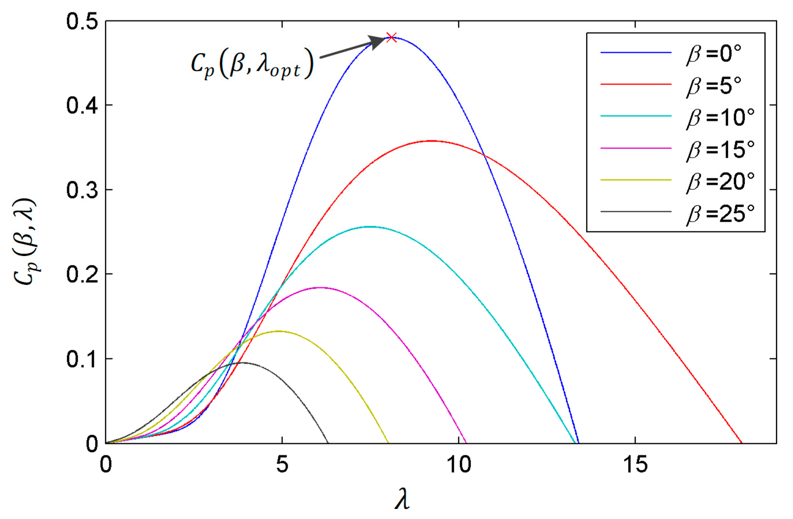
The power coefficient described in Equations (3)–(5) for different attack angles and speed ratios is shown in
Figure 2. As can be seen in this figure,
reaches a maximum value for a given
, known as the optimal
(
). For the model presented in Equations (3)–(5), the
takes a value of 8.1, and with this value, the
reaches a maximum value of 0.48 when
. Therefore,
represents the speed ratio with which the power of the wind is transformed into mechanical power to the greatest extent possible. This means that for a given wind speed, the turbine has an angular speed (
) at which the greatest possible amount of energy is extracted. This angular speed can be determined by substituting
in Equation (3), resulting in Equation (6).
Knowing the angular velocity of the blades and the transferred mechanical power, the mechanical torque
exerted by the blades on the PMSG is calculated according to Equation (7).
Solving
from Equation (3) and expressing the area of Equation (1) as
, Equation (7) is expressed as shown in Equation (8).
In the case of the wind system studied in this investigation, the term
can be expressed as a function
since the attack angle is fixed. This simplification expresses the mechanical torque as shown in Equation (9).
Opposed to the mechanical torque, there is an electromagnetic torque
that is generated due to the magnetic fields of the rotor and stator. This torque is calculated using Equation (10), where
is the number of PMSG poles,
is the constant magnetic flux of the rotor magnets, and
is the component of the stator current in the q-direction.
With both torques defined and given that the turbine under study does not have a gear transmission, Equation (11) describes the dynamics of the rotation of the blades. In this equation,
is the combined inertia of the PMSG, blades, and rotor, and
is the combined coefficient of friction.
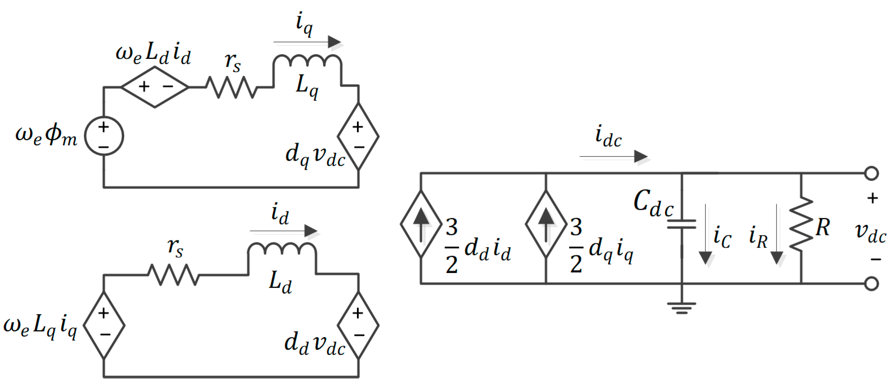
To define the component of the stator current in the q-direction, the equivalent circuit of the electrical part of the wind system is considered, including the generator and the three-phase rectifier with a resistive load
connected on the DC side, in dq coordinates as shown in
Figure 3. A more detailed proceeding to obtain this model is presented in [
41,
42].
In this circuit,
is the electrical circular frequency of the PMSG and is calculated according to Equation (12).
is the stator phase resistance,
is the DC side capacitor,
is the DC bus level,
and
are the modulation signal, and
and
are the direct and quadrature stator inductances.
Finally, applying Kirchhoff’s laws to the circuit in
Figure 3, Equations (13)–(15) are obtained, which define the electrical model of the wind system, including the PMSG and the three-phase AC/DC CEP.
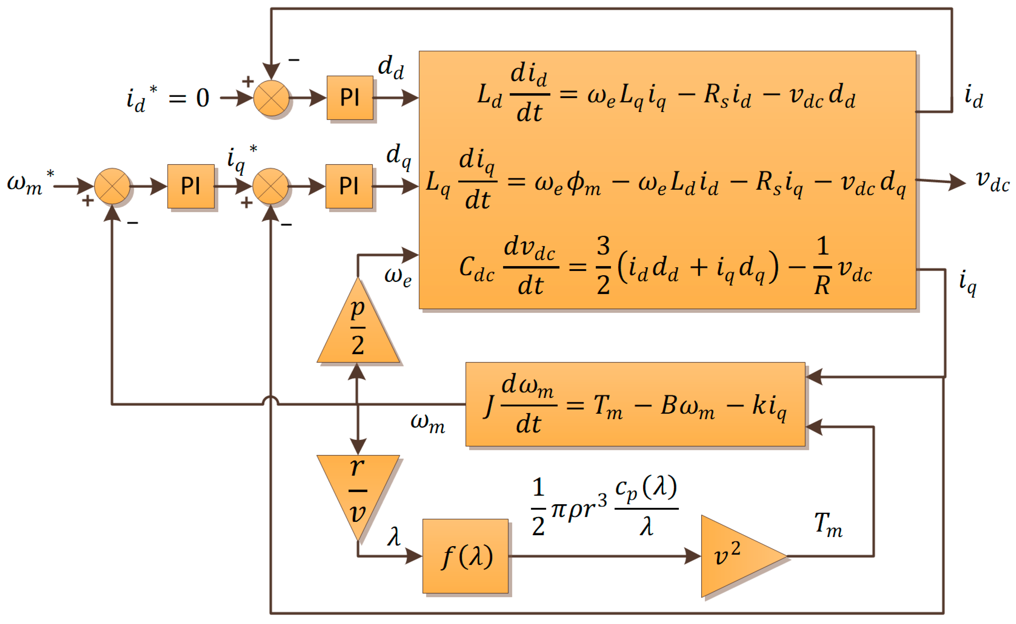
Synthesizing the modeling of the wind system described by Equations (1)–(15) and including the PI controllers for the schematic of
Figure 1, this system is represented as a block diagram in
Figure 4.
The diagram presented in
Figure 4 does not include the AC dynamics of the PMSG and the AC side of the three-phase CEP. Consequently, it does not include the abc/dq and dq/αβ transformations or the three-phase modulator shown in
Figure 1. Given that the wind system is proposed as a distributed generator for a DCµG, the model in dq coordinates provides sufficient dynamic response for its analysis in this context.
4. Hardware-in-the-Loop Implementation
The HIL platform in this research was implemented on an NI myRIO 1900 development board (myRIO), which features a System on Chip (SoC) Xilinx Zynq-7010 integrating a real-time processor and an FPGA with a 40 MHz clock. The processor and the FPGA communication are employed through the ARM Advanced Microcontroller Bus Architecture (AMBA) standard (AMBA Specification (Rev 2). ARM Limited: 1999). To embed the model of the wind system in the FPGA of the myRIO, Equations (11)–(15) were discretized using the backward Euler approximation [
34], resulting in Equations (16)–(19). Equation (20) was proposed to implement the PI controllers, where
is the proportional gain,
is the integral gain,
is the control signal, and
is the error. In these equations,
represents the integration time and takes a value of 10 µs.
In addition to these equations, the system model includes the nonlinear function and the nonlinear operations and . On the other hand, the control algorithm involves solving the nonlinear Equations (1) to (8) to determine as a function of . The function and the relation were implemented in the FPGA with one-dimension look-up tables (1D-LUTs). The nonlinear operations and are solved on a PC and sent to a real-time processor via USB and then to the FPGA via AMBA as inputs. The dynamic of the wind speed is relatively slow compared to that implemented in the FPGA, so the difference in the execution time between the PC and the FPGA does not significantly affect the dynamic response of the wind system. Thus, only linear operations are solved in the FPGA while maintaining small integration periods. This data flow from the PC to the FPGA, which could be bidirectional, adds a communication layer to the HIL platform, allowing the wind system to be integrated into a more complex energy system, such as a µG, which is the goal of this distributed generator.
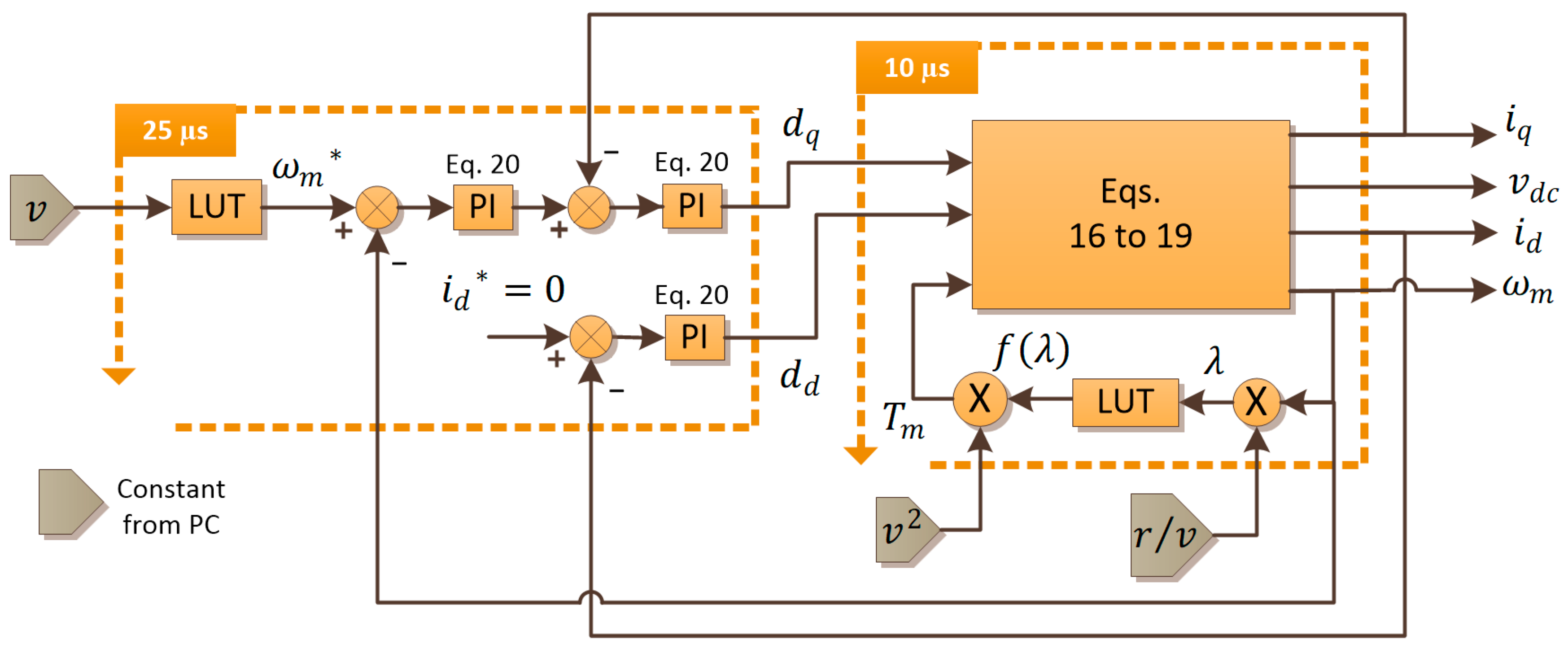
The wind system model and control system were organized on the FPGA of the myRIO in two loops. The first loop includes Equations (16)–(19) and a 1D-LUT for the function
and is executed every 10 µs. The second loop includes a 1D-LUT for the function
and three PI controllers implemented with Equation (20), running every 25 µs. In
Figure 7, the layout of the wind system and the control algorithm on the myRIO are shown. With this division, the control algorithm can be modified without altering the loop containing the wind system model. On the other hand,
Figure 8 shows the HIL platform composed of a PC to emulate the wind behavior, the NI myRIO 1900, and a four-channel oscilloscope for monitoring the variables
,
,
, and
.
The parameters used to feed the wind system model are presented in
Table 1 and correspond to the Anelion SW 3.5 GT turbine (Anelion Smart Power, Rafelbuñol, Spain), which has a generation capacity of 3.5 kW and is referenced in [
46].
Table 1 also includes the gains (P and I) of the PI controllers; the subscript q indicates that the gains belong to the PI that produces
, the subscript d is for the PI that produces
, and the subscript d is for the PI that produces
.
5. Results
To validate the operation of the wind system, the results obtained from the hardware implementation were compared with the results of a continuous model simulation in Matlab. The first experiment evaluated the system’s response to a stepped wind speed profile, starting with a value of 6 m/s, then transitioning to 17.5 m/s, and finally returning to 8 m/s. The variables compared included the angular velocity of the blades, the currents in the q and d directions, and the DC voltage. These comparisons are shown in
Figure 9, items (a) to (d), respectively. The platform’s accuracy in reproducing these variables’ behavior was measured by calculating the mean absolute error using the simulation values as a reference. The errors found for
,
,
, and
correspond to 0.7 rad/s, 1.9 A, 0.04 A, and 9.5 V.
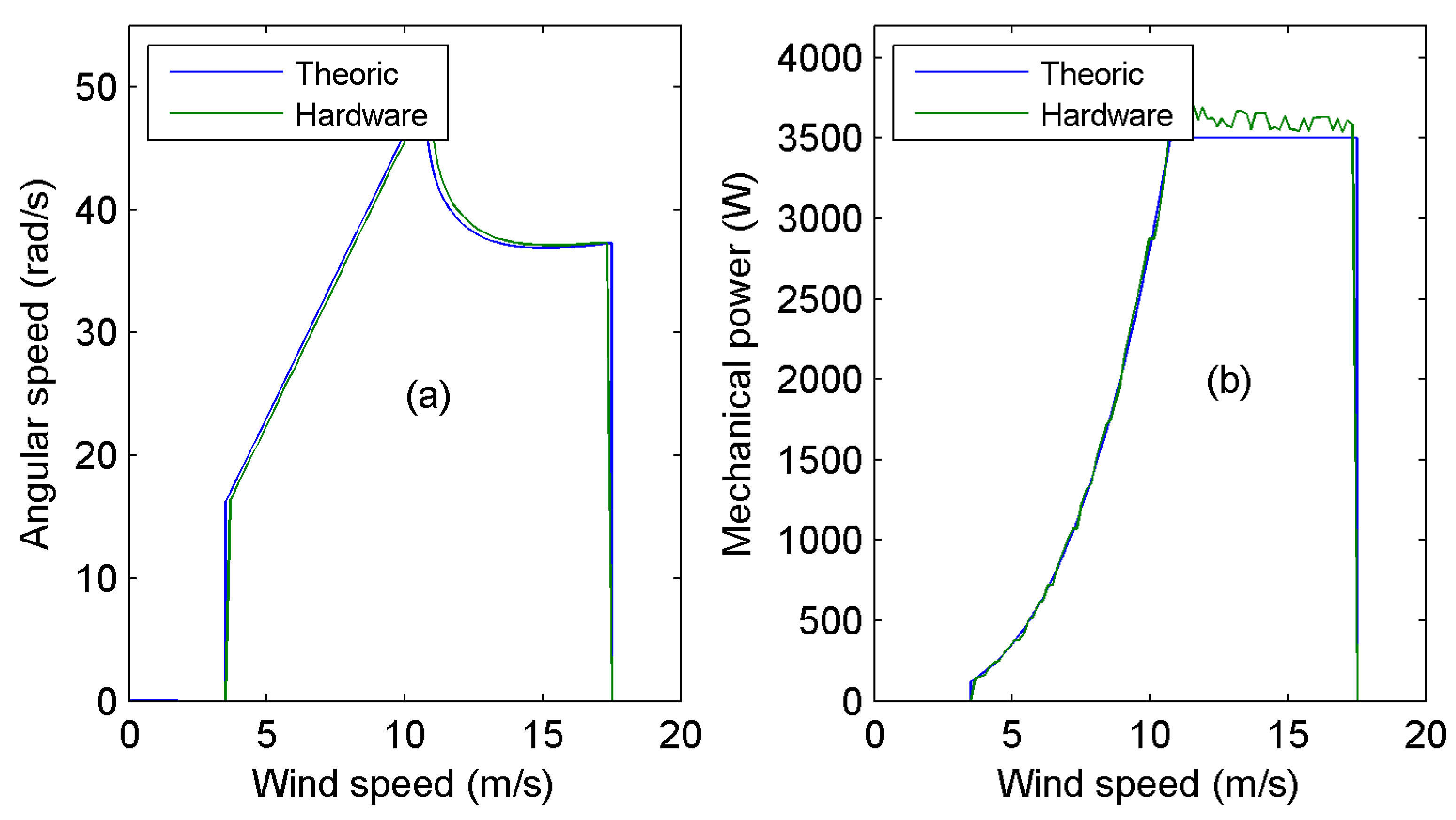
Once the correct reproduction of the wind system’s behavior in hardware was verified, it was tested throughout the generation range to validate the operation of the control algorithm. The results of this experiment are shown in
Figure 10 and
Figure 11.
Figure 10a compares the angular velocity of the proposed control algorithm and the angular velocity of the implemented system. This angular speed satisfies the constraints described in
Figure 6, extracting the maximum power when possible and keeping the system within its operation limits when the power increases.
Figure 10b illustrates the implemented system’s operating curve compared to the theoretical one. This figure shows that the controller can extract the maximum power in the whole operating range.
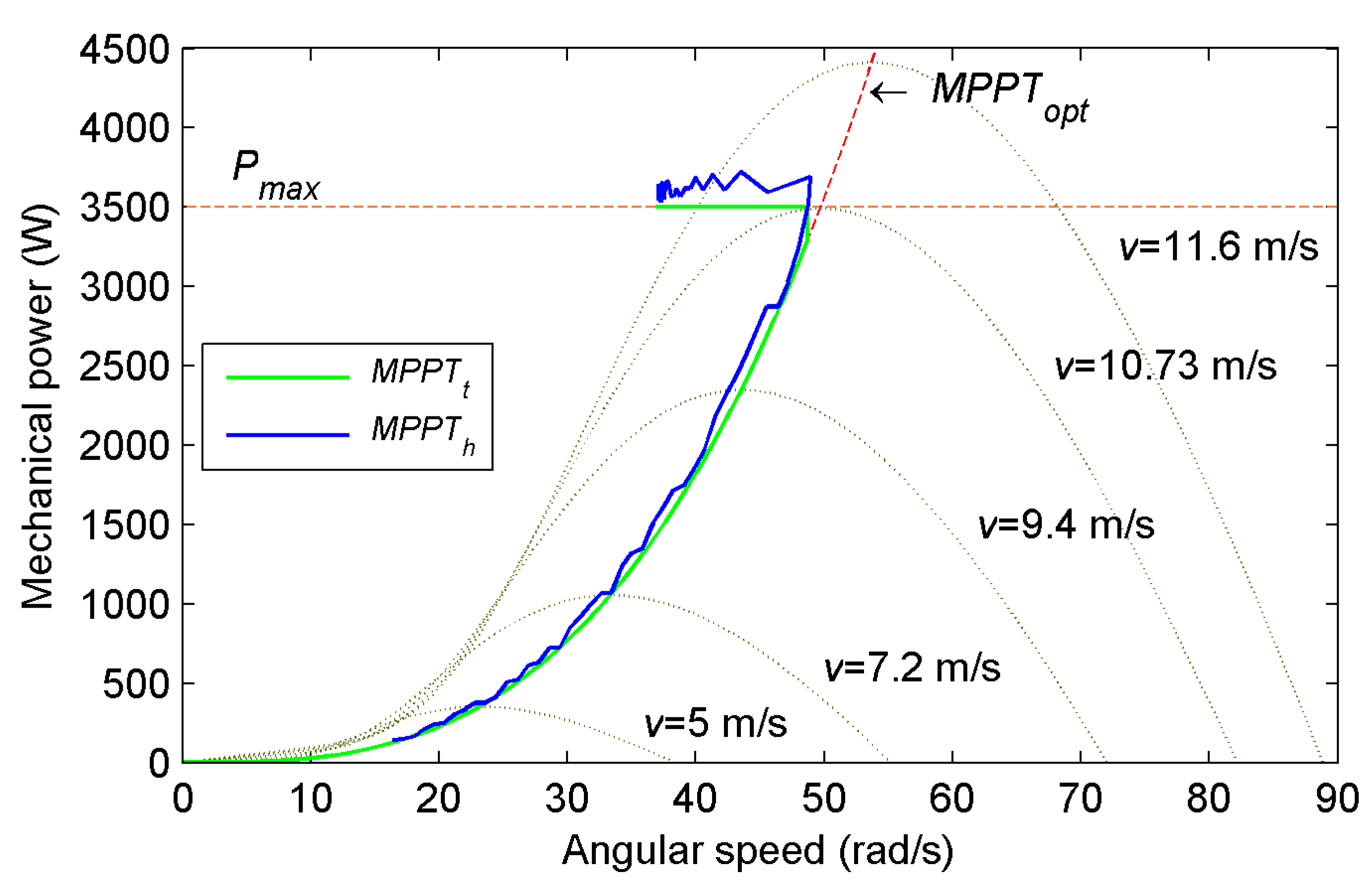
Figure 11 shows the trajectory followed by the mechanical power of the system. In this figure, the dotted red line labeled
represents the theoretical optimal trajectory that touches the maxima of the extracted mechanical power function for any wind speed. The extracted mechanical functions are presented with gray dotted lines for different speeds. These curves have similar shapes to the
function presented in
Figure 3. As can be seen in
Figure 11, for each value of wind speed, there is an angular speed that reaches the maximum value of the extracted mechanical function; this is the value that satisfies Equation (6). Ideally, a wind system should extract the maximum power for every wind speed. However, the mechanical power that the turbine can support is reached for a specific value. The dotted red line
represents the limit power the studied wind system can extract. The green line,
, represents the theoretical trajectory of the studied system. This trajectory follows the
line until the limit angular velocity is reached (segment B of
Figure 6), then it rises vertically while maintaining
constant and increasing
until the trajectory intersects the
line (segment C of
Figure 6). From this point,
begins to decrease, maintaining the trajectory on the
line (segment D of
Figure 6) until reaching the upper cut-off wind speed of the operating range. Finally, the blue line,
, represents the trajectory followed by the wind system implemented with the control algorithm. As shown in
Figure 11, the
trajectory follows the
trajectory satisfactorily; this implies that the controller behavior is as expected. Therefore, this implies that the HIL platform is useful for testing the wind system in its whole operation range. Here, it is essential to highlight that this controller is used for validating the usefulness of the platform, but not only this controller can be tested.
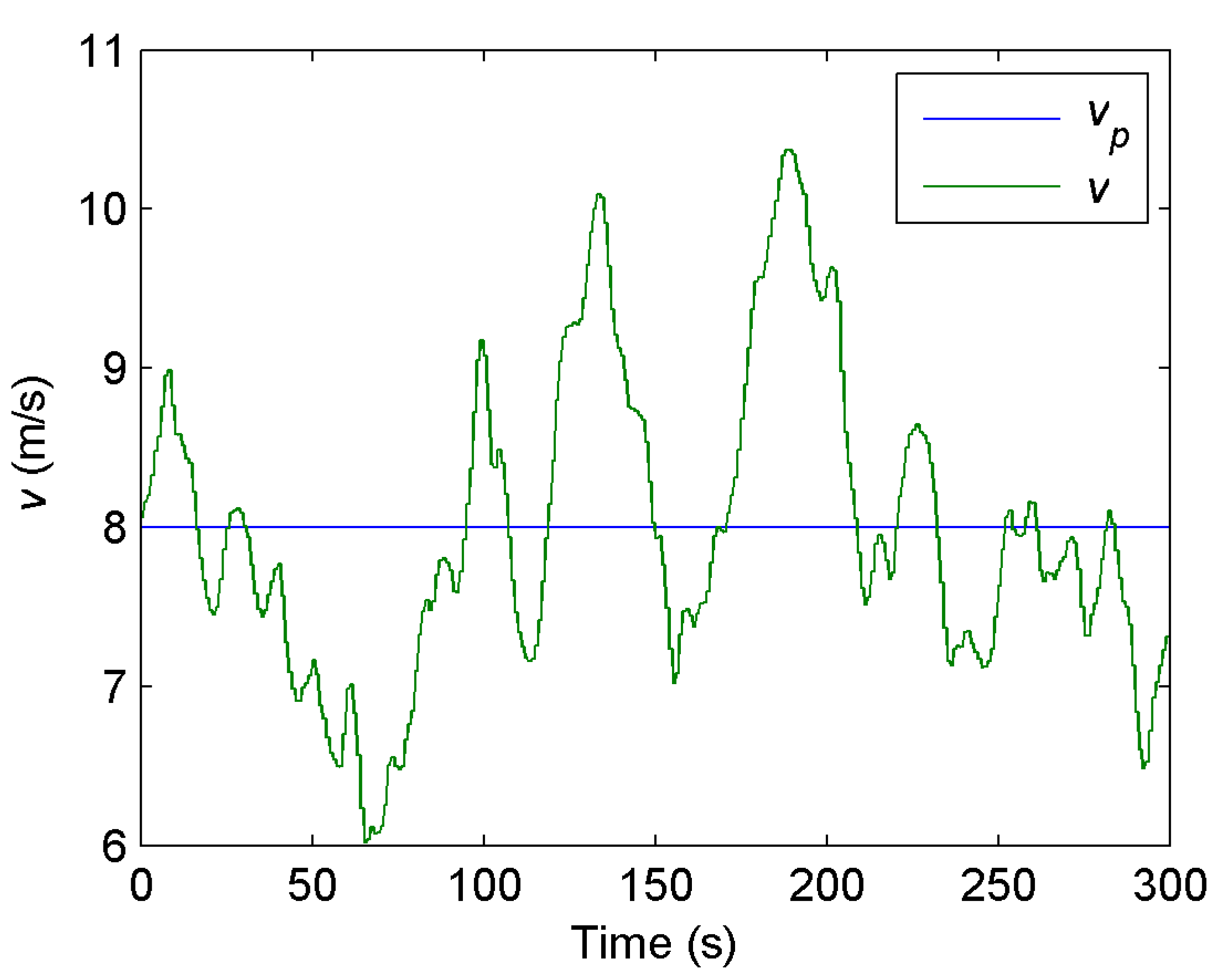
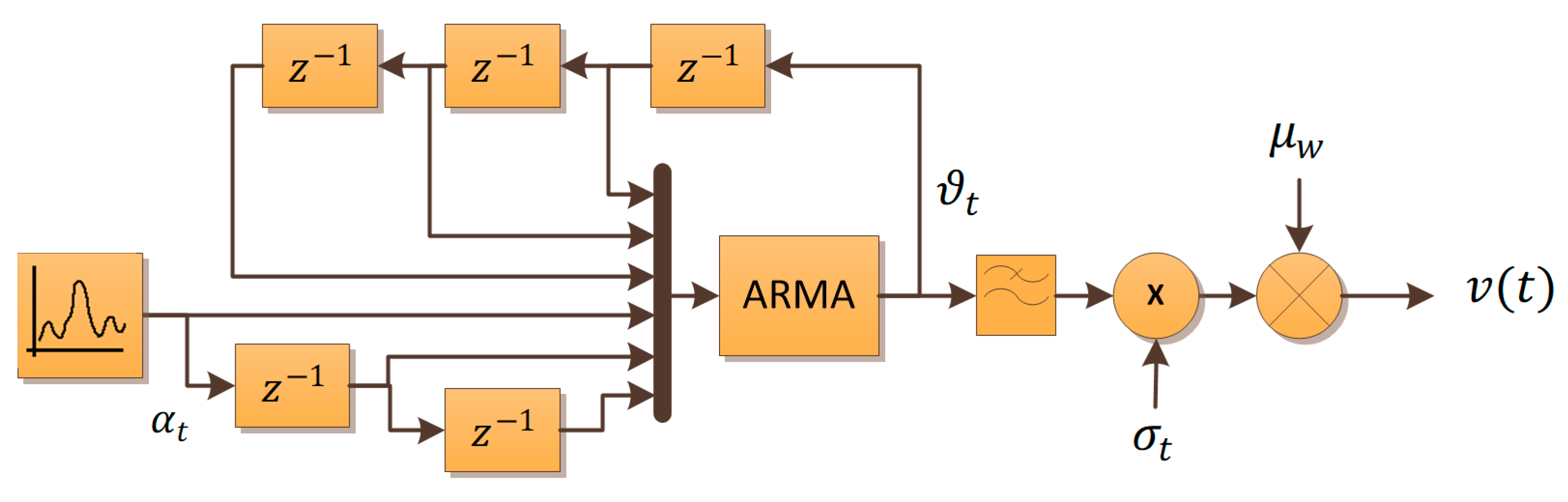
Finally, to test the system with wind behavior, including gusts, an autoregressive moving average (ARMA) model was implemented. This model generates a wind profile with a normal distribution based on a specified mean and variance [
47]. This algorithm models the wind speed
according to Equation (21) as the sum of two components: an average speed
and an instantaneous turbulence
, which is modeled as a first-order Gaussian noise-excited filter as shown in Equation (22) (where
is the time constant, and
represents Gaussian noise with a mean of 0). With the filtered noise, the instantaneous turbulence is expressed in Equation (23), where
is the standard deviation of the wind speed, and
is the ARMA time series model expressed in Equation (24). This algorithm was implemented with the block diagram shown in
Figure 12.
Using the ARMA model, the control algorithm was tested with a wind profile featuring an average speed of 8 m/s and a standard deviation of 0.5 m/s. The experiment lasted 5 min, during which 300 values for the wind speed were generated, one every second. The purpose of this experiment was to verify the operation of the controller in maintaining the turbine operating in
. The variables analyzed are the angular speed of the blades and the speed ratio.
Figure 13 shows the wind speed used in the experiment,
Figure 14a illustrates the angular velocity response, and
Figure 14b shows the speed ratio compared to the optimum.
6. Conclusions
The distribution within the FPGA allows the modification of the control algorithm without altering the wind system model, establishing a Controller Hardware in the Loop platform. This platform enables the validation of an embedded controller, represented by the 25 µs loop, before its implementation in the field. The controller’s validation does not imply the addition of new hardware, while the resources available in the FPGA are not exceeded, in addition to the fact that, since it is integrated with the myRIO, its description is performed using a high-level graphic language. Moreover, compared to platforms presented in [
12,
26,
27,
28,
29], the one developed in this work represents a more cost-effective alternative.
The comparison shown in
Figure 9 and the errors obtained in this comparison validate the HIL platform’s ability to emulate the wind system’s behavior. Therefore, the controller is validated under conditions that closely resemble reality. This holds true even when comparing the platform with software simulation rather than a real system since the used model is widely accepted in the field.
Including nonlinear functions such as 1D-LUTs and implementing linear operations in a separate instance from the FPGA allows the platform to operate with high latency, resulting in integration times of 10 µs for the wind system model. All of this is achieved using hardware with relatively limited resources.
The platform adequately analyzes the wind system as a distributed generator for a DCµG. However, if its use is considered in a context where AC dynamics must be analyzed, it must include transformations that generate AC signals.
In [
45], a control algorithm like the one used in this work to validate the HIL platform is presented. The system used in [
45] is a lab-scale prototype with a real PMSG driven by a permanent magnet synchronous motor (PMSM). At the same time, the PMSM is driven by an inverter operating in the torque control mode, with the torque established by an emulator based on the TMS320F2812 DSP. The trajectory followed by the control algorithm in our work is like the one presented in [
45]. The fact that the HIL platform reproduces the trajectory implies that it is useful for validating the control strategy. This algorithm was used only to test the platform, but others can be validated. In this context, the platform implemented in this research serves as a valuable research infrastructure for testing MPPT control algorithms. This field is of interest, as evidenced in the introduction section:
References [
5,
6] mention the importance of wind systems as distributed generators in microgrids.
References [
7,
8,
9,
10,
11] are examples of research published in high-impact journals from 2020 to 2023 that use wind systems in microgrids. These works confirm the significance and current relevance of wind systems mentioned in [
5,
6].
References [
12,
13] emphasize the importance of studying algorithms for maximum power point tracking in wind systems.
References [
14,
15,
16,
17,
18], published from 2019 to 2022, underscore the relevance and significance of studying algorithms for maximum power point tracking in wind systems.
References [
19,
20,
21,
22] highlight the utility of hardware in the loop for validating control algorithms. This utility is demonstrated in references [
12,
23,
24,
25,
26,
27,
28,
29,
30,
31,
32,
33].
Considering all aspects mentioned, the main findings and contribution of this research are summarized next:
The distribution of nonlinear behaviors and equations in different hardware instances allows the implementation of the wind system in relatively cost-effective and limited hardware.
Implementing the controller and the model in different loops provides a C-HIL scheme that allows testing different control algorithms without modifying the system model.
The results show that the hardware can accurately reproduce the system behavior.
To obtain the expected results, implementing a well-known controller proves the platform’s usefulness for validating control algorithms.
For future research, the integration of the developed platform into a DCµG with additional components, such as other generators and energy storage systems, is proposed. Managing a DCµG requires a hierarchical control structure, usually a tertiary one, which can be centralized or decentralized. This control structure sets control objectives to fulfill an energy management strategy in all cases. Since the wind system represents a clean, distributed energy resource and is highly dependent on environmental factors with significant variability, the most common energy management strategy aims to extract the maximum possible power from this system. Therefore, the MPPT is the most crucial local control for this system. At the same time, the communication layer is the crucial aspect of establishing a hierarchical control structure. The developed HIL platform includes a communication flow between an FPGA and a PC through a real-time processor. This communication will be sufficient for implementing this control architecture in the future.
Parallel with this development, other elements for composing a DCµG are being implemented using the same hardware. The elements under development include a photovoltaic system, an AC/DC PEC for the main grid interconnection, a battery bank, a supercapacitor bank, and variable DC loads. The system presented in this work is just an element of a future platform for emulating a whole DCµG. Although the digital device used in this research to emulate the wind system has relatively limited hardware resources, at the same time, it has three input–output (I/O) ports with both digital and analog I/O. Through these ports, communication can be established between multiple devices, emulating more complex systems modularly. This allows the dynamics of different subsystems to be distributed and, therefore, the computational requirement, managing to emulate complex and reconfigurable systems with relatively limited hardware. The DCμG of which the generator described in this research will be part is made up of three myRIOs. In one of them, a photovoltaic system, variable DC loads, a battery bank, and the dynamics of the DC bus are emulated. The utility network and a bidirectional AC/DC PEC are emulated in another. Finally, the third is presented in this research, where the wind system is emulated.
A characteristic that has motivated the development of HIL simulations is that the systems under test can be tested under conditions very close to reality. In this sense, future work to improve the platform presented in this research will integrate IoT for measuring wind speed in the field. Although the ARMA algorithm used in this research to emulate wind is a well-accepted approach, using real measurements will provide more information on the algorithm’s performance for the MPPT evaluated with the developed platform.


 ,
, 


