Abstract
Battery state estimation is fundamental to battery management systems (BMSs). An accurate model is needed to describe the dynamic behavior of the battery to evaluate the fundamental quantities, such as the state of charge (SOC) or the state of health (SOH). This paper presents an overview of the most commonly used battery models, the equivalent electrical circuits, and data-driven ones, discussing the importance of battery modeling and the various approaches used to model lithium batteries. In particular, it provides a detailed analysis of the electrical circuit models commonly used for lithium batteries, including equivalent circuit and thermal models. Furthermore, a comprehensive overview of data-driven approaches is presented. The advantages and limitations of each type of model are discussed. Finally, the paper concludes with a discussion of current research trends and future directions in the field of battery modeling.
1. Introduction
Lithium batteries are the most promising technology for electric vehicles (EVs) and energy storage systems (ESSs). The main goals for each battery-powered system are to extend the battery’s lifetime and improve its reliability. The battery management system (BMS) represents a pivotal component in the real-time monitoring of battery conditions. Since it is impossible to have a direct measurement, the battery information, such as the remaining charge, needs to be estimated using model-based estimation algorithms. The battery models presented in the literature mainly fall into the following two main categories: the model-based, such as electrical equivalent circuit, and the data-driven methods, such as neural network and support vector machine. The model-based methods, such as equivalent electrical circuits (ECMs), are the most widely used to study the dynamics of the battery [1,2,3,4,5,6,7]. The ECMs involve representing the complex electrochemical processes occurring within a battery as a simplified circuit with various components. Engineers and researchers can analyze and simulate the battery’s performance under different conditions [8,9,10,11]. The equivalent circuit model typically consists of idealized components such as resistors, capacitors, and voltage sources, representing the various physical phenomena occurring within the battery [12,13,14,15,16]. These components are interconnected to mimic the battery’s internal resistance, capacitance, and voltage dynamics. Using this modeling technique makes it possible to study the battery’s response to different loads, charging and discharging rates, temperature variations, and other factors [17,18]. It enables the estimation of essential battery parameters like state of charge (SoC), state of health (SoH), internal resistance, and capacity [19,20,21,22,23]. Battery modeling through equivalent electrical circuits is crucial in various applications, including electric vehicles, renewable energy systems, portable electronics, and grid energy storage [24,25,26,27,28,29]. It helps optimize battery designs, develop battery management systems, and predict battery performance over time.
However, it is essential to note that the model’s accuracy depends on the chosen circuit topology and the availability of accurate battery characterization data. Actual batteries are complex systems with non-linear behavior, and creating an accurate equivalent circuit model requires careful consideration of various factors.
For this reason, data-driven methods have become increasingly popular in battery modeling thanks to their ability to describe complex non-linear phenomena. These models use machine learning techniques to learn the relationship between input variables (such as state of charge, temperature, and current) and output variables (such as voltage and capacity) from a large dataset of battery measurements.
This overview aims to present a detailed analysis of the most used models in the literature. The paper is mainly organized as follows: Section 2 describes the most commonly used ECMs, from the simplest to the most complex. Kinetic and thermal models are presented in Section 3. Section 4 illustrates the data-driven approaches. Finally, results and conclusions are drawn.
2. Equivalent Electrical Circuit Models
To adequately simulate the battery storage of a complex system such as the one in Figure 1, ensuring a certain degree of accuracy at the minimum error and minimum computational cost, it is possible to refer to electrochemical, electrical, or “data-driven” models. The electrochemical ones require a considerable processing time to compute the information associated with chemical reactions at the microscopic level [30,31]. On the other hand, the analytical–mathematical models exploit empirical equations to exclusively and rapidly estimate characteristics of efficiency and residual charge without, however, allowing the evaluation of the internal parameters and the relationship between voltage and current at the terminals. Therefore, electrical models are the most versatile for analyzing a battery’s static and dynamic behavior, expressed through voltage or current generators, resistors, and capacitors [32]. It should be noted that a model often used in BESS to relate the battery power to the state of charge [33] is the so-called generic model, which expresses the SOC as a function of the energy stored in the battery relative to its maximum capacity. An increasing or decreasing trend occurs depending on whether the battery itself is in charge or discharge as follows:
where the power in Equation (1) indicates the charge power (>0), while in Equation (2) that of discharge (<0). () Moreover, () indicate the charging and discharging efficiencies, respectively, and depend on the particular technology [34,35] and the energy capacity of the system (). This model allows evaluating the relation without specifying in which operating context (voltage, current) this occurs. Therefore, it is clear that an assessment of the dynamic behavior of the battery as a function of the SOC is important to understand its operation better. In mathematical terms, this is equivalent to saying that the voltage at the terminals can be expressed as a function (f) of the SOC, current, and temperature Equation (3):
In which the function f regulates the dynamics of the battery, meaning the latter is at a macroscopic level (battery pack).
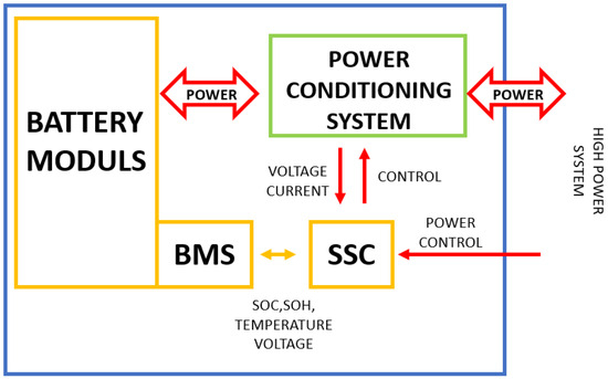
Figure 1.
BESS block scheme.
2.1. Simple Battery Model
The most straightforward version present in the literature is the simple battery model [36,37], which allows a quantitative study of battery behavior without excessively investigating the internal electrochemical processes. The following electrical circuit model (ECM) consists of an ideal voltage generator, the , and an (internal) series resistance, such as , both generally dependent quantities from the SOC and temperature.
The equation describing the circuit in Figure 2 is:
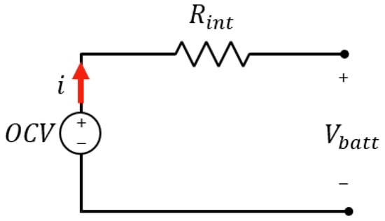
Figure 2.
Simple battery model.
The open-circuit voltage represents the voltage at the terminals under no-load (equilibrium) conditions. It has a non-linear relationship with the SOC, while contributes to evaluating the instantaneous response of the battery and limits the internal current flow. As described in [38,39], it is influenced by two main terms: the electronic resistance, depending on the resistivity of the materials, and the ionic resistance, which relates the current flow to the electrochemical internal processes (ion mobility, conductivity of the electrolyte and effective surface area of the electrodes). Also, this internal resistance allows investigating the degradation mechanism, as it tends to increase with it, being related to the SOH.
2.2. Equivalent Electrical Circuit—1RC
The circuit of Figure 3 allows the study of the dynamic and transient behavior; a parallel RC network is added to model the transient response caused by the flow of lithium ions in the electrolyte, and in the negative electrode , and respectively constitute the resistance and the polarization capacity. These terms describe how the voltage varies as a function of the current. These parameters, as well as the and , are functions of the SOC and the battery temperature [40].
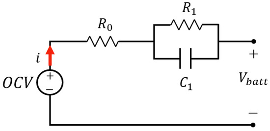
Figure 3.
Thevenin equivalent electrical circuit 1RC.
Therefore, the dynamic behavior of the voltage is obtained by applying Kirchhoff’s law (KVL) to the circuit in Figure 3, as follows Equation (5):
In which the can be obtained by applying Ohm’s first law for the resistance and the characteristic equation of the capacitor, respectively, reported below Equations (6) and (7):
In which, given the topology of the circuit, for each instant of time, the voltage is expressed as = = . While applying Kirchhoff’s law, it is possible to express the current affecting the battery as Equation (8):
which is valid for each instant of time, and it can be rewritten taking into account Equations (6) and (7) as follows:
For the considerations made, the previous one becomes:
In addition, using the previous (Equation (10)) and (Equations (6) and (7)), it is possible to express the voltage affecting the RC network as follows:
The resolution of the differential Equation (11), then inserted in Equation (5), allows for the investigation of the dynamic behavior of the battery (diffusive phenomena between the electrodes) over time, i.e., of the response to a current excitation through the time constant [41].
2.3. Equivalent Electrical Circuit—nRC
The previous model can be generalized to n-RC networks (Figure 4) to introduce more time constants and, therefore, analyze the behavior of the ESS in greater detail. However, the complexity increases the computational cost since it is necessary to extract the values of each component of the equivalent circuit to identify the experimental curves, thus reducing the possibility of use in real-time-type applications.
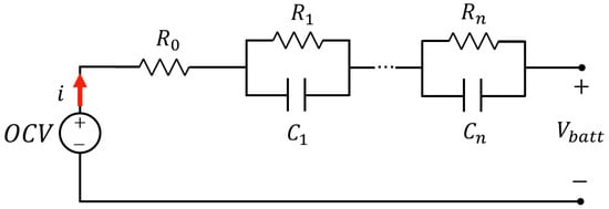
Figure 4.
n-th-order generalized circuit.
The 2RC model of Figure 4 offers an excellent compromise between precision and computational cost. It has two distinct time constants and relating to two phases of the voltage transient, one faster and a slower one (respectively). From a physical point of view, as mentioned in the previous section, RC networks are associated with ion diffusion in the electrolyte and porous active elements (electrodes), with charge transfer, and with the electric double layer effect (electric double dayer (EDL)) [42]. The latter constitutes a region (established between an electric conductor and an ionic one, in this case, the electrolyte, on account of the local inhomogeneities of the charge) in which the electrochemical phenomena occur, which mainly influences the electronic flow so that during the charging phenomena the cations present in the cathode–electrolyte interface will be removed leaving many solvents available and thus amplifying the electrolyte decomposition phenomena [40,43]. Analyzing the circuit in Figure 5, it is clear how the previous one in Equation (5) is modified by adding the term due to the second RC network, i.e.,:
Similar to what is reported in the previous section, for this circuit, it is possible to obtain the following:
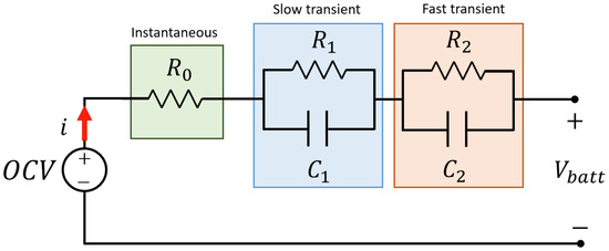
Figure 5.
Second-order electrical equivalent circuit.
Figure 6 shows in more detail the behavior of the circuit in Figure 5 in response to a generic current variation (impulsive in the specific case proposed). The resistance represents the instantaneous voltage contribution in the transition between the no-load circuit and the load connected. The resistance can be evaluated by analyzing, using Ohm’s law, the ohmic drop following the previous cyclic phase (charge or discharge). The ohmic drop is evaluated by the ratio between the difference between the end charge (or discharge) voltage and the voltage at the first instant of inversion of the relative curve (as evident in the figure by AV variation) and the current involved in the process (this must be doubled if the same current is used in the transition between phases). However, this parameter depends non-linearly on temperature and SOC.
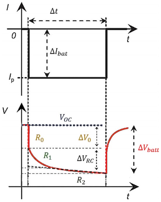
Figure 6.
Response of the 2RC-type ECM to a current pulse in the PDT test, “Pulse Discharge Test” [44].
The parallel network , is associated with the fast time constant , whose contribution describes the behavior of the battery concerning transient phenomena of short duration, being associated with the electrochemical polarization for the transfer of the charge [41,45]. In parallel, the , network is associated with transient phenomena of longer duration (with slow time constant ) linked to polarization by concentration (changes in the concentration of the electrolyte due to the electronic flow at the interface with the electrodes); therefore, it depends on the formation of a concentration gradient in correspondence with the ion diffusion or the relaxation phase [41,46,47,48]. For these reasons, this model is also defined as a double polarization model, or DP, and allows the tracking of internal electrochemical phenomena responsible for the non-linear relationship between voltage at the terminals and residual charge. In addition, the resistances and capacities of the two networks RC also depend on the state of charge and the temperature, as will be detailed below, being , necessary to characterize the dynamic response during the transfer of energy (therefore power) between the battery and the mains/load. Furthermore, the dependencies on the state of charge and the temperature are contained directly in the model.
2.4. General Non-Linear Model
The 1RC and 2RC models presented can be equipped with an additional bulk capacitor placed in series with the , respectively, giving rise to the PNGV (Partnership for a New Generation of Vehicles) and GNL (general non-linear) model in which this additional element models the variations of this voltage during load application and reflects the capacity of the storage system [43,49,50,51,52] (Figure 7). These dependencies will be integrated into the 2RC model, taking into account an accurate identification of the , exploiting special discharges at low C-rates, and a precise imposition of the capacity exhibited by the cell concerning the discharge power and the operating temperature.
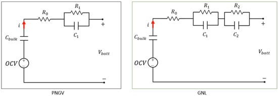
Figure 7.
PNGV and GNL equivalent electrical circuit.
2.5. RC Equivalent Model
This model exploits two capacitors and three resistors, as evident in Figure 8, noting how the ideal voltage generator associated with the open-circuit voltage is absent . In detail [41,47], the capacitor , of modest value, models the effects of the surface nature of the storage and the double layer (EDL). In contrast, represents the battery’s energy capacity (storage charge) and has a decidedly higher value than the previous one.
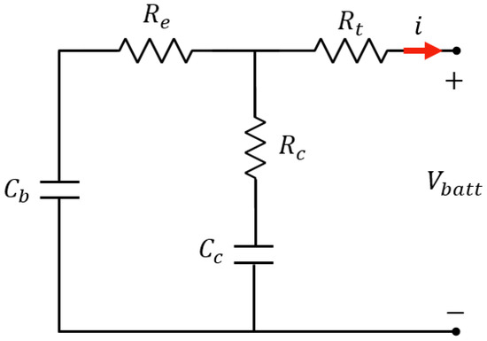
Figure 8.
RC equivalent electrical circuit.
On the other hand, the resistances , , and , respectively, constitute the losses associated with the terminal section (interfacing with the external load), those associated with the final section and the series resistance capacitor loss ratio (ESR), which describes the Joule losses. Knowing the conventions of Figure 8, the model is described by the following coupled equations [40,41,47]:
where Equation (17) represents the transfer function relating the output voltage to the current source. Although this model has the same number of passive components compared to the DP, the latter, however, remains superior. These comparative evaluations further reaffirm the validity of the choice of the 2RC or double polarization model.
Comparing the 1RC dynamic model with the 2RC dynamic model, it was found that the 2RC model provides a more accurate representation of battery behavior, particularly in terms of voltage and capacity estimation. The additional resistor-capacitor element in the 2RC model allows for better modeling of the battery’s internal resistance and polarization effects, leading to improved accuracy in predicting battery performance.
When comparing the PNGV and LNG models with the RC equivalent model, it was found that the RC equivalent model provides a more straightforward and more computationally efficient approach to battery modeling. However, the PNGV and LNG models offer more detailed representations of battery behavior, particularly regarding thermal and aging effects. As such, the choice of model depends on the specific application and level of detail required for accurate battery management.
Overall, while each model has strengths and weaknesses, using electrical circuit models for lithium batteries is crucial for effective battery management and optimization.
3. State of Charge and Temperature Evaluation
The state of charge and the operating temperature strongly influence the models presented in the previous sections. Therefore, to accurately describe the storage system, it is necessary to introduce a model estimating the SOC and a thermal model evaluating the temperature profile.
3.1. Thermal Model
The temperature directly influences the performance of the storage system. There is a relationship capable of regulating the heat exchange with the surrounding environment, also influencing the variability of the characteristic parameters of the representative model. Each identified parameter must refer to a specific temperature value or range.
To model the temperature variation and the heat exchange, the dissipated power by the Joule effect must be considered. Figure 9 shows a model in which the thermal power is evaluated according to electrical equivalent components as a current generator, the thermal resistance () characteristic of the thermal gradient present in the exchange (temperature differences between ESS and external environment), and finally the storage system as a thermal capacity (). The upper and lower potentials of the circuit refer, respectively, to the temperature detected for the storage system (measured by temperature sensors) and at the reference temperature of 0 °C, indicated as the mass reference in electrical terms. In addition, thermal resistance comes between the (thermal) potential of the ESS and the correlated one to the heat exchange with the external reference temperature (controlled) in order to guarantee a non-instantaneous response to possible sudden variations in the external temperature [47].
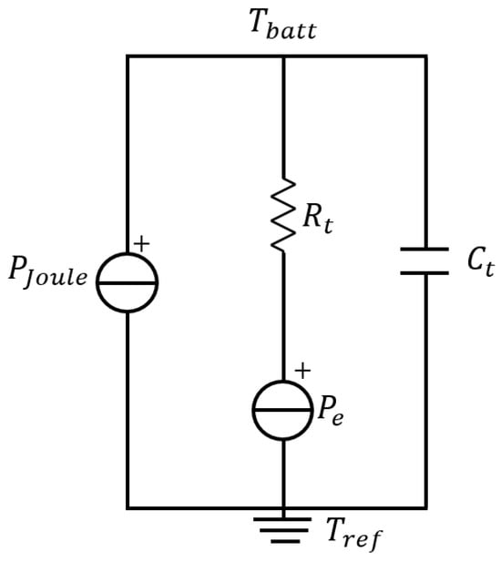
Figure 9.
Thermal model adopted to monitor the temperature variations of the BESS.
In this way, the cell temperature, indicated with That, can be expressed as follows in the energy balance [47]:
By solving in the Laplace domain (s), it is possible to obtain from the previous one the temperature profile in the compact form:
It is adaptable to the specification of the 2RC model adopted by obtaining, the relationship between and the electrical quantities of the circuit:
In detail, it should be noted that ; where is the coefficient of convective heat exchange with the surrounding environment (air), expressed in (W m−2 K−1) and is the surface area of the storage system, therefore based on the dimensional analysis it follows that this resistance is expressed in (K/W). In parallel, is a function of the specific heat of the constituent material ESS, expressed in J kg−1 K−1, and its mass (expressed in kg) and precisely its value can be estimated using a unique optimization algorithm in which the temperature profile recorded by the BMS is compared with the one simulated following the previous equations.
As demonstrated in [53,54,55], it is clear that the variation of the model parameters is significant in correspondence with decidedly accentuated variations, i.e., with gradients even higher than 10 °C; therefore, it is legitimate to state that for insignificant variations in the temperature profile the parameters can be considered unchanged, i.e., not explanatory of particular changes in their values. It should be specified that the environments in which the BESSs are placed have an actively controlled temperature in order to stabilize performance and avoid possible excessive increases (or reductions) such as to jeopardize behavior (such as thermal leaks, although in such contexts, there is also the corrective intervention of the BMS) and at the same time convective heat exchange mechanisms are implemented with the surrounding environment described by the following relationship:
Observing how refers to the temperature profile as a function of time, obtainable from (3.36) as follows:
where the non-instantaneous response to temperature change is modeled by the response constant .
3.2. Kinetic Battery Model
As for the temperature profile, it is necessary to monitor the behavior of the SOC, which is such a crucial parameter for analyzing the circuit’s behavior in response to a current excitation and contributing to the identification phase of the 2RC electrical parameters. In literature, the Kinetic Battery model is combined with the 2RC model to evaluate the state of charge. This model supposes the battery as a structure composed of two wells, Figure 10, one contains the available charge, which flows directly into the load, while the other contains the bound charge, which refills the available charge well through a valve, k. The difference between good heights regulates the exchanged charge. represents the SOC that becomes zero when the battery is fully discharged.
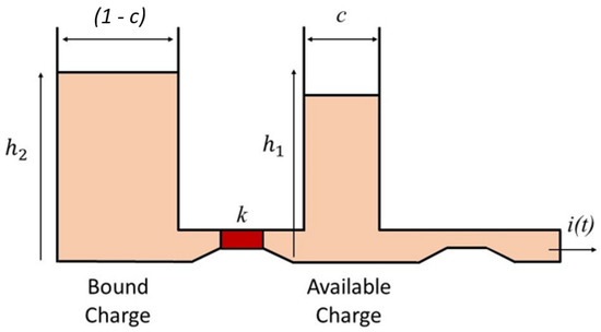
Figure 10.
Kinetic model.
The SOC can be expressed as:
where and are the available and maximum battery capabilities, respectively. is computed in detail in [56].
4. Data-Driven Models
Data-driven models have become increasingly popular in battery modeling due to their ability to accurately capture complex non-linear behaviors and their flexibility in handling various data types. These models use machine learning techniques to learn the relationship between input variables (such as state of charge, temperature, and current) and output variables (such as voltage and capacity) from a large dataset of battery measurements. One advantage of data-driven models is their ability to capture the dynamic behavior of batteries, which is crucial for accurate state estimation and prediction. Traditional physics-based models often rely on simplified assumptions and may not be able to capture the full complexity of battery behavior. On the other hand, data-driven models can learn from large datasets and adapt to changes in battery behavior over time. Another advantage of data-driven models is their ability to handle different data types, such as time-series data or images of electrode microstructures. This allows for a more holistic approach to battery modeling, where multiple data types can be integrated to provide a more comprehensive understanding of battery behavior. However, one challenge in using data-driven models for battery modeling is the need for high-quality data. This requires careful experimental design and data collection procedures. Unbalanced data would cause a model to be subjected to overfitting and underfitting in decision-making [57]. These issues are well addressed, and the researchers have developed general guidelines to address the problem [58]. Additionally, the choice of machine learning algorithms and model architecture can significantly impact the performance and interpretability of the model (Figure 11). Despite these challenges, data-driven models have shown promising results in accurately predicting battery behavior and have the potential to improve battery management systems significantly. As more data becomes available and machine learning techniques continue to advance, data-driven models are expected to play a significant role in the future of battery modeling.
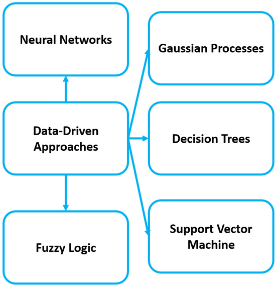
Figure 11.
Data-driven approaches.
Several machine learning techniques can be used in the data-driven approach for battery modeling. These include:
- Artificial Neural Networks (ANNs): ANNs are a type of machine learning algorithm that is inspired by the structure and function of the human brain (Figure 12). They consist of interconnected nodes or neurons that process and transmit information. ANNs are well suited for battery modeling as they can handle complex relationships between input and output variables. One specific application of ANNs in battery modeling is the state of charge (SOC) estimation. SOC is a critical parameter for battery management as it represents the amount of charge remaining in a battery and is crucial for determining its performance and lifespan. ANNs are particularly well suited for SOC estimation as they can handle complex relationships between input variables, such as voltage, current, and temperature, and the output variable of SOC. The training process involves feeding the ANN with a large dataset of input–output pairs, where the input variables represent the battery’s operating conditions and the output variable is the corresponding SOC value. The ANN then learns the relationship between the input and output variables and creates a mathematical model to predict the SOC for new input data accurately. This model can then be used in real-time to estimate the SOC of a battery based on its current operating conditions. One advantage of using ANNs for SOC estimation is their ability to handle non-linear relationships between input and output variables. This is particularly useful for batteries as their behavior can be highly non-linear and dependent on various factors such as temperature and aging. Moreover, ANNs can also be trained to account for different battery chemistries, making them versatile for use with different types of batteries. This is important as different battery chemistries have different charge–discharge characteristics, and an accurate SOC estimation model must consider this. Neural networks have recently been used in several works to evaluate the SOC parameter of batteries. Table 1 summarizes the various results.
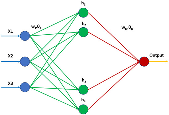 Figure 12. The general architecture of the 3-layer neural network.

Table 1.
NN used for SOC estimation.
Table 1.
NN used for SOC estimation.
| Method | Inputs | Error |
|---|---|---|
| Multi-layer BPNN [59] | - | Relative error: <4.5% |
| BPNN-BSA [60] | , , | RMSE at 25 °C: 0.81% for DST, for 0.91% for FUDS |
| Single hidden layer FNN with PCA [61] | , | MSE: 0.004% at 25 °C |
| Two hidden layer FNN [62] | , , | Max. RMSE: 1.75% |
| Two hidden layer FNN with EKF for charging SoC estimation [63] | , | 1.62% RMSE using UDDS vehicle dynamic profile |
| DFNN [64] | , , , | MAE: 1.10% at 25 °C |
| Hierarchical ensemble ELM [65] | VVTI during CC part of charging and discharging profile | RMSE: 1.26% |
| ASO-ELM for series-connected battery pack [66] | , , capacity | RMSE: 0.007 |
| LSTM-CNN [67] | , , , , | RMSE: 1.35% |
| GRU-CNN with Kalman filter [68] | , | Max RMSE: 0.385% |
- 2.
- Support Vector Machines (SVMs): SVMs are supervised learning algorithms that can be used for classification and regression tasks. They work by finding the optimal hyperplane that separates data points into different classes or predicts a continuous output variable (Figure 13). SVMs are effective for battery modeling as they can handle high-dimensional data and non-linear relationships. In battery SOC estimation, SVMs can be trained using a dataset of input variables such as voltage, current, temperature, and corresponding SOC values. The SVM then finds the hyperplane that can best separate the data points and create a model that can accurately predict the SOC for new input data. Additionally, SVMs have a robust generalization ability, meaning they can perform well on unseen data. This is important for battery SOC estimation as the model needs to accurately predict the SOC for various operating conditions, not just the ones it was trained on. Furthermore, SVMs effectively handle noisy data, which is common in battery systems due to external factors such as sensor errors or variations in battery chemistry. By accounting for noise in the training process, SVMs can create a more accurate SOC estimation model. Table 2 shows a summary of the works in which SVM was used for SoC estimation.
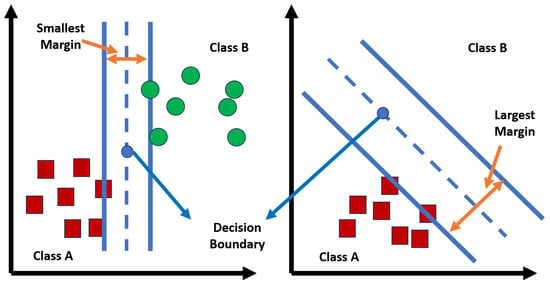 Figure 13. SVM algorithm.

Table 2.
Summary of the contributions that used SVMs for SoC estimation.
Table 2.
Summary of the contributions that used SVMs for SoC estimation.
| Method | Inputs | Error |
|---|---|---|
| LS-SVM with AUKF [69] | , | Absolute error: <3% |
| SVR with double search-optimized hyper-parameters [70] | , , Power | Max. MSE: 2.23% |
| Classification SVR with PCA [44] | - | MSE: 0.00495% |
| SVR with PSO optimized hyperparameters [71] | , , | Average estimation error: 1.5% |
| LS-SVM [72] | , , SoH | Max. Error: <2% |
| Online SVR [73] | - | RMSE: 0.0172 |
- 3.
- Decision Trees: Decision trees are supervised learning algorithms that use a tree-like structure to make predictions based on a series of if-then rules. They are handy for battery modeling as they can handle numerical and categorical data and easily handle variables’ interactions.
- 4.
- Random Forests: Random forests are an ensemble learning technique that combines multiple decision trees to make predictions. They create many decision trees and use the average prediction from all the trees to make the final prediction. Random forests are useful for battery modeling as they can handle high-dimensional data and reduce overfitting.
- 5.
- Gaussian Processes (GPs): Gaussian processes are a probabilistic machine learning technique that can be used for regression tasks [74,75]. They work by modeling the relationship between input and output variables as a Gaussian distribution, allowing for uncertainty in the predictions. Since the forecast is based on a Gaussian distribution, the forecast can be improved using adaptive fitting [76]. The typical trend of a GPR model is illustrated in Figure 14.
 Figure 14. GPR model.Gaussian processes are helpful for battery modeling as they can handle noisy and sparse data. GPs are a powerful machine learning technique that can be used for battery SOC estimation. One advantage of using GPs for SOC estimation is their ability to handle non-linear relationships between input and output variables. Batteries exhibit non-linear behavior due to aging, temperature, and discharge rate. Traditional linear models need help to capture these complexities, leading to inaccurate SOC estimations. GPs, on the other hand, can capture these non-linear relationships and provide more accurate predictions. Another significant advantage of GPs is their ability to estimate uncertainty for their predictions. This is crucial for battery management as it allows for more informed decision-making. Batteries are subject to various uncertainties, such as measurement errors and environmental factors, which can affect their performance and lead to potential failures. By considering the uncertainty in the SOC estimation, battery management systems can take appropriate actions to prevent failures and ensure optimal battery performance.
 - 6.
- Fuzzy Logic: Fuzzy logic is another popular approach for battery SOC estimation. Fuzzy logic is a mathematical framework that can handle imprecise and uncertain information, making it well suited for battery systems that exhibit non-linear and uncertain behavior. In fuzzy logic, input variables such as voltage, current, and temperature are mapped to linguistic terms such as “low”, “medium”, and “high”. These terms are then used to define fuzzy sets, which represent the different states of the battery. The rules for how these input variables affect the SOC are defined using expert knowledge and experience. The fuzzy logic system then takes in the linguistic inputs and uses these rules to calculate the SOC. One advantage of this approach is its ability to handle imprecise and uncertain inputs. Batteries often experience variations in their behavior due to aging and environmental conditions. Fuzzy logic can account for these uncertainties and provide more accurate SOC estimations. Another advantage of fuzzy logic is its interpretability. The rules used in the fuzzy logic system can be easily understood by humans, making it easier to validate and improve the model. This is particularly useful for battery management systems, where it is essential to understand clearly how the SOC estimation is calculated. However, one limitation of fuzzy logic is that it relies heavily on expert knowledge and assumptions about the data. This can be a disadvantage in cases where the data is complex and cannot be easily captured by simple rules. Additionally, fuzzy logic may need help handling large datasets, as it requires significant computational resources to process linguistic inputs and apply rules.
Overall, the choice of machine learning technique will depend on the specific goals and characteristics of the battery modeling project. It is essential to carefully consider the data and problem to determine the most suitable approach.
5. Conclusions
The electrical circuit modeling of lithium-ion batteries through electrical circuit models and data-driven approaches plays a crucial role in accurately estimating parameters and state of charge (SOC) for battery management systems (BMS) in electric vehicles and other applications. The research in this area focuses on developing accurate models that can capture the dynamic behavior of lithium-ion batteries under different operating conditions and driving styles. Furthermore, the research also delves into comparing different battery modeling methods, including electrical circuits and data-driven models, for accurate SOC estimation in BMS. The study compares the pros and cons of these modeling methods and explores future research directions in this domain.
In particular, for the electrical circuit model, the comparison between the 1RC dynamic model and the 2RC dynamic model revealed that the 2RC model provides a more accurate representation of battery behavior, particularly regarding voltage and capacity estimation. The additional resistor-capacitor element in the 2RC model allows for better modeling of the battery’s internal resistance and polarization effects, leading to improved accuracy in predicting battery performance. On the other hand, when comparing the PNGV and LNG models with the RC equivalent model, it was found that the RC equivalent model provides a more straightforward and computationally efficient approach to battery modeling. However, the PNGV and LNG models offer more detailed representations of battery behavior, particularly regarding thermal and aging effects. The choice of model depends on the specific application and the level of detail required for accurate battery management.
The data-driven approach to model lithium-ion batteries addresses the inconsistent and varied characteristics of battery cells, which pose challenges for battery pack modeling. This approach aims to reduce computational work while maintaining good model accuracy. The data-driven approach offers a promising solution to the challenges of modeling lithium-ion batteries, particularly in electric vehicle applications. By leveraging data-driven methods, researchers aim to enhance the accuracy and efficiency of battery modeling, contributing to the development of advanced battery management systems for electric vehicles and renewable energy storage applications. In conclusion, the research on electrical circuit modeling of lithium-ion batteries through electrical circuit models and data-driven approaches provides valuable insights into developing accurate and reliable models for battery management systems, ensuring the safe and efficient operation of electric vehicles and other applications.
Author Contributions
Conceptualization, V.L., M.Q., A.L. and F.R.F.; methodology, V.L., M.Q., A.L. and F.R.F.; data curation, V.L., M.Q., A.L. and F.R.F.; writing—original draft preparation, V.L., M.Q., A.L. and F.R.F.; writing—review and editing, V.L., M.Q., A.L. and F.R.F. All authors have read and agreed to the published version of the manuscript.
Funding
This research received no external funding.
Data Availability Statement
No new data available.
Conflicts of Interest
The authors declare no conflict of interest.
References
- Schmitt, J.; Horstkötter, I.; Bäker, B. Electrical lithium-ion battery models based on recurrent neural networks: A holistic approach. J. Energy Storage 2023, 58, 106461. [Google Scholar] [CrossRef]
- Krishnamoorthy, U.; Gandhi Ayyavu, P.; Panchal, H.; Shanmugam, D.; Balasubramani, S.; Al-rubaie, A.J.; Al-khaykan, A.; Oza, A.D.; Hembrom, S.; Patel, T.; et al. Efficient Battery Models for Performance Studies-Lithium Ion and Nickel Metal Hydride Battery. Batteries 2023, 9, 52. [Google Scholar] [CrossRef]
- Çorapsiz, M.R.; Kahveci, H. A study on Li-ion battery and supercapacitor design for hybrid energy storage systems. Energy Storage 2023, 5, e386. [Google Scholar] [CrossRef]
- Shin, J.; Kim, W.; Yoo, K.; Kim, H.; Han, M. Vehicular level battery modeling and its application to battery electric vehicle simulation. J. Power Sources 2023, 556, 232531. [Google Scholar] [CrossRef]
- Navas, S.J.; González, G.C.; Pino, F.; Guerra, J. Modelling Li-ion batteries using equivalent circuits for renewable energy applications. Energy Rep. 2023, 9, 4456–4465. [Google Scholar] [CrossRef]
- Quelin, A.; Damay, N. Coupling electrical parameters of a battery equivalent circuit model to electrodes dimensions. J. Power Sources 2023, 561, 232690. [Google Scholar] [CrossRef]
- Canova, A.; Campanelli, F.; Quercio, M. Flywheel Energy Storage System in Italian Regional Transport Railways: A Case Study. Energies 2022, 15, 1096. [Google Scholar] [CrossRef]
- Pillai, P.; Nguyen, J.; Balasingam, B. Performance analysis of empirical open-circuit voltage modeling in lithium ion batteries, part-1: Performance measures. arXiv 2023, arXiv:2306.16542. [Google Scholar]
- Hassini, M.; Redondo-Iglesias, E.; Venet, P. Second-Life Batteries Modeling for Performance Tracking in a Mobile Charging Station. World Electr. Veh. J. 2023, 14, 94. [Google Scholar] [CrossRef]
- Petri, E.; Reynaudo, T.; Postoyan, R.; Astolfi, D.; Nesic, D.; Rael, S. State estimation of an electrochemical lithium-ion battery model: Improved observer performance by hybrid redesign. arXiv 2023, arXiv:2304.09680. [Google Scholar]
- Wang, J.; Gao, S.; Zhu, J.; Mao, J. Thermal performance analysis and burning questions of refrigerant direct cooling for electric vehicle battery. Appl. Therm. Eng. 2023, 232, 121055. [Google Scholar] [CrossRef]
- Choi, W.; Shin, H.C.; Kim, J.M.; Choi, J.Y.; Yoon, W.S. Modeling and applications of electrochemical impedance spectroscopy (EIS) for lithium-ion batteries. J. Electrochem. Sci. Technol. 2020, 11, 1–13. [Google Scholar] [CrossRef]
- Tran, M.K.; DaCosta, A.; Mevawalla, A.; Panchal, S.; Fowler, M. Comparative study of equivalent circuit models performance in four common lithium-ion batteries: LFP, NMC, LMO, NCA. Batteries 2021, 7, 51. [Google Scholar] [CrossRef]
- Kroeze, R.C.; Krein, P.T. Electrical battery model for use in dynamic electric vehicle simulations. In Proceedings of the 2008 IEEE Power Electronics Specialists Conference, Rhodes, Greece, 15–19 June 2008; IEEE: Piscataway, NJ, USA, 2008; pp. 1336–1342. [Google Scholar]
- Chen, M.; Rincon-Mora, G.A. Accurate electrical battery model capable of predicting runtime and IV performance. IEEE Trans. Energy Convers. 2006, 21, 504–511. [Google Scholar] [CrossRef]
- Fotouhi, A.; Auger, D.J.; Propp, K.; Longo, S.; Wild, M. A review on electric vehicle battery modelling: From Lithium-ion toward Lithium–Sulphur. Renew. Sustain. Energy Rev. 2016, 56, 1008–1021. [Google Scholar] [CrossRef]
- Bibin, C.; Vijayaram, M.; Suriya, V.; Ganesh, R.S.; Soundarraj, S. A review on thermal issues in Li-ion battery and recent advancements in battery thermal management system. Mater. Today Proc. 2020, 33, 116–128. [Google Scholar] [CrossRef]
- Tran, M.K.; Mathew, M.; Janhunen, S.; Panchal, S.; Raahemifar, K.; Fraser, R.; Fowler, M. A comprehensive equivalent circuit model for lithium-ion batteries, incorporating the effects of state of health, state of charge, and temperature on model parameters. J. Energy Storage 2021, 43, 103252. [Google Scholar] [CrossRef]
- Hallmann, M.; Wenge, C.; Komarnicki, P.; Balischewski, S. Methods for lithium-based battery energy storage SOC estimation. Part I: Overview. Arch. Electr. Eng. 2022, 71, 139–157. [Google Scholar]
- Xiao, R.; Hu, Y.; Jia, X.; Chen, G. A novel estimation of state of charge for the lithium-ion battery in electric vehicle without open circuit voltage experiment. Energy 2022, 243, 123072. [Google Scholar] [CrossRef]
- Solomon, O.O.; Zheng, W.; Chen, J.; Qiao, Z. State of charge estimation of Lithium-ion battery using an improved fractional-order extended Kalman filter. J. Energy Storage 2022, 49, 104007. [Google Scholar] [CrossRef]
- Lai, X.; Wang, S.; Ma, S.; Xie, J.; Zheng, Y. Parameter sensitivity analysis and simplification of equivalent circuit model for the state of charge of lithium-ion batteries. Electrochim. Acta 2020, 330, 135239. [Google Scholar] [CrossRef]
- Adaikkappan, M.; Sathiyamoorthy, N. Modeling, state of charge estimation, and charging of lithium-ion battery in electric vehicle: A review. Int. J. Energy Res. 2022, 46, 2141–2165. [Google Scholar] [CrossRef]
- Madani, S.S.; Schaltz, E.; Knudsen Kær, S. An electrical equivalent circuit model of a lithium titanate oxide battery. Batteries 2019, 5, 31. [Google Scholar] [CrossRef]
- Soltani, M.; Beheshti, S.H. A comprehensive review of lithium ion capacitor: Development, modelling, thermal management and applications. J. Energy Storage 2021, 34, 102019. [Google Scholar] [CrossRef]
- Chen, W.; Liang, J.; Yang, Z.; Li, G. A review of lithium-ion battery for electric vehicle applications and beyond. Energy Procedia 2019, 158, 4363–4368. [Google Scholar] [CrossRef]
- Liu, X.; Li, W.; Zhou, A. PNGV equivalent circuit model and SOC estimation algorithm for lithium battery pack adopted in AGV vehicle. IEEE Access 2018, 6, 23639–23647. [Google Scholar] [CrossRef]
- Canova, A.; Giaccone, L.; Quercio, M. A proposal for performance evaluation of low frequency shielding efficiency. In Proceedings of the CIRED 2021—The 26th International Conference and Exhibition on Electricity Distribution, Online, 20–23 September 2021; Volume 2021, pp. 935–939. [Google Scholar] [CrossRef]
- Canova, A.; Quercio, M. A Shielding System Proposal for the Cabling of Electric Glass Melters. IEEE Open J. Ind. Appl. 2023, 4, 1–10. [Google Scholar] [CrossRef]
- Von Srbik, M.T. Advanced Lithium-Ion Battery Modelling for Automotive Applications. Ph.D. Thesis, Imperial College London, London, UK, 2015. [Google Scholar]
- Smith, K.A. Electrochemical Modeling, Estimation and Control of Lithium Ion Batteries. Ph.D. Thesis, Pennsylvania University, Philadelphia, PA, USA, 2007. [Google Scholar]
- Camas-Náfate, M.; Coronado-Mendoza, A.; Vega-Gómez, C.J.; Espinosa-Moreno, F. Modeling and Simulation of a Commercial Lithium-Ion Battery with Charge Cycle Predictions. Sustainability 2022, 14, 14035. [Google Scholar] [CrossRef]
- Yang, Y.; Bremner, S.; Menictas, C.; Kay, M. Modelling and optimal energy management for battery energy storage systems in renewable energy systems: A review. Renew. Sustain. Energy Rev. 2022, 167, 112671. [Google Scholar] [CrossRef]
- Divya, K.; Østergaard, J. Battery energy storage technology for power systems—An overview. Electr. Power Syst. Res. 2009, 79, 511–520. [Google Scholar] [CrossRef]
- Rodrigues, E.; Osório, G.; Godina, R.; Bizuayehu, A.; Lujano-Rojas, J.; Matias, J.; Catalão, J. Modelling and sizing of NaS (sodium sulfur) battery energy storage system for extending wind power performance in Crete Island. Energy 2015, 90, 1606–1617. [Google Scholar] [CrossRef]
- ostigov. PNGV Battery Test Manual; USDOE Assistant Secretary for Energy Efficiency and Renewable Energy: Washington, DC, USA, 1997. [CrossRef][Green Version]
- Johnson, V. Battery performance models in ADVISOR. J. Power Sources 2002, 110, 321–329. [Google Scholar] [CrossRef]
- Razi, M.F.I.M.; Daud, Z.H.C.; Asus, Z.; Mazali, I.I.; Ardani, M.I.; Hamid, M.K.A. Li-NMC Battery Internal Resistance at Wide Range of Temperature. J. Adv. Res. Fluid Mech. Therm. Sci. 2022, 99, 9–16. [Google Scholar]
- Anseán, D.; González, M.; Viera, J.C.; Garcia, V.M.; Alvarez, J.C.; Blanco, C. Electric vehicle Li-Ion battery evaluation based on internal resistance analysis. In Proceedings of the 2014 IEEE Vehicle Power and Propulsion Conference (VPPC), Coimbra, Portugal, 27–30 October 2014; IEEE: Piscataway, NJ, USA, 2014; pp. 1–6. [Google Scholar]
- Singirikonda, S.; Obulesu, Y. Battery modelling and state of charge estimation methods for Energy Management in Electric Vehicle-A review. IOP Conf. Ser. Mater. Sci. Eng. 2020, 937, 012046. [Google Scholar] [CrossRef]
- He, H.; Xiong, R.; Fan, J. Evaluation of lithium-ion battery equivalent circuit models for state of charge estimation by an experimental approach. Energies 2011, 4, 582–598. [Google Scholar] [CrossRef]
- Zhang, W.; Lu, Y.; Wan, L.; Zhou, P.; Xia, Y.; Yan, S.; Chen, X.; Zhou, H.; Dong, H.; Liu, K. Engineering a passivating electric double layer for high performance lithium metal batteries. Nat. Commun. 2022, 13, 2029. [Google Scholar] [CrossRef] [PubMed]
- Meng, J.; Luo, G.; Ricco, M.; Swierczynski, M.; Stroe, D.I.; Teodorescu, R. Overview of lithium-ion battery modeling methods for state-of-charge estimation in electrical vehicles. Appl. Sci. 2018, 8, 659. [Google Scholar] [CrossRef]
- Xuan, L.; Qian, L.; Chen, J.; Bai, X.; Wu, B. State-of-Charge Prediction of Battery Management System Based on Principal Component Analysis and Improved Support Vector Machine for Regression. IEEE Access 2020, 8, 164693–164704. [Google Scholar] [CrossRef]
- Kalogiannis, T.; Hosen, M.S.; Sokkeh, M.A.; Goutam, S.; Jaguemont, J.; Jin, L.; Qiao, G.; Berecibar, M.; Van Mierlo, J. Comparative study on parameter identification methods for dual-polarization lithium-ion equivalent circuit model. Energies 2019, 12, 4031. [Google Scholar] [CrossRef]
- Brivio, C. Battery Energy Storage Systems: Modelling, Applications and Design Criteria. Master’s Thesis, Politecnico di Milano, Milano, Italy, 2017. [Google Scholar]
- Nutricato, R. Modelli Elettrici e Stima dei Parametri di Batterie al Litio. Master’s Thesis, Università Politecnica delle Marche, Ancona, Italy, 2021. [Google Scholar]
- Stolz, L.; Winter, M.; Kasnatscheew, J. Concentration Polarization in Batteries: Theory, Experimental Verification and Practical Relevance. Electrochem. Soc. Meet. Abstr. 2022, 241, 250. [Google Scholar] [CrossRef]
- Aung, H.; Low, K.S.; Soon, J.J. State-of-charge estimation using particle swarm optimization with inverse barrier constraint in a nanosatellite. In Proceedings of the 2015 IEEE 10th Conference on Industrial Electronics and Applications (ICIEA), Auckland, New Zealand, 15–17 June 2015; IEEE: Piscataway, NJ, USA, 2015; pp. 1–6. [Google Scholar]
- Geng, Y.; Pang, H.; Liu, X. State-of-charge estimation for lithium-ion battery based on PNGV model and particle filter algorithm. J. Power Electron. 2022, 22, 1154–1164. [Google Scholar] [CrossRef]
- Gou, Y.; Han, X. Study of SOC dynamic estimation method of power lithium battery. IOP Conf. Ser. Mater. Sci. Eng. 2018, 452, 032057. [Google Scholar] [CrossRef]
- Yan, X.W.; Guo, Y.W.; Cui, Y.; Wang, Y.W.; Deng, H.R. Electric vehicle battery soc estimation based on gnl model adaptive kalman filter. J. Phys. Conf. Ser. 2018, 1087, 052027. [Google Scholar] [CrossRef]
- Xu, Y.; Hu, M.; Fu, C.; Cao, K.; Su, Z.; Yang, Z. State of charge estimation for lithium-ion batteries based on temperature-dependent second-order RC model. Electronics 2019, 8, 1012. [Google Scholar] [CrossRef]
- Nikolian, A.; Jaguemont, J.; De Hoog, J.; Goutam, S.; Omar, N.; Van Den Bossche, P.; Van Mierlo, J. Complete cell-level lithium-ion electrical ECM model for different chemistries (NMC, LFP, LTO) and temperatures (−5 °C to 45 °C)–Optimized modelling techniques. Int. J. Electr. Power Energy Syst. 2018, 98, 133–146. [Google Scholar] [CrossRef]
- Wang, Q.; Gao, T.; Li, X. SOC Estimation of Lithium-Ion Battery Based on Equivalent Circuit Model with Variable Parameters. Energies 2022, 15, 5829. [Google Scholar] [CrossRef]
- Kim, T.; Qiao, W. A hybrid battery model capable of capturing dynamic circuit characteristics and nonlinear capacity effects. IEEE Trans. Energy Convers. 2011, 26, 1172–1180. [Google Scholar] [CrossRef]
- Domingos, P. A few useful things to know about machine learning. Commun. ACM 2012, 55, 78–87. [Google Scholar] [CrossRef]
- Bishop, C.M.; Nasrabadi, N.M. Pattern Recognition and Machine Learning; Springer: Berlin/Heidelberg, Germany, 2006; Volume 4. [Google Scholar]
- Zhang, G.; Xia, B.; Wang, J. Intelligent state of charge estimation of lithium-ion batteries based on L-M optimized back-propagation neural network. J. Energy Storage 2021, 44, 103442. [Google Scholar] [CrossRef]
- Hannan, M.A.; Lipu, M.S.H.; Hussain, A.; Saad, M.H.; Ayob, A. Neural Network Approach for Estimating State of Charge of Lithium-Ion Battery Using Backtracking Search Algorithm. IEEE Access 2018, 6, 10069–10079. [Google Scholar] [CrossRef]
- Lipu, M.H.; Hannan, M.; Hussain, A. Feature selection and optimal neural network algorithm for the state of charge estimation of lithium-ion battery for electric vehicle application. Int. J. Renew. Energy Res. (IJRER) 2017, 7, 1700–1708. [Google Scholar]
- Bhattacharyya, H.S.; Choudhury, A.B.; Kumar Chanda, C. Performance Analysis of a Lithium-ion Battery Pack in EV Application Using an Auto-Upgraded Neural Network Model. In Proceedings of the 2019 8th International Conference on Power Systems (ICPS), Jaipur, India, 20–22 December 2019; pp. 1–6. [Google Scholar] [CrossRef]
- Zhou, N.; Liang, H.; Cui, J.; Chen, Z.; Fang, Z. A Fusion-Based Method of State-of-Charge Online Estimation for Lithium-Ion Batteries Under Low Capacity Conditions. Front. Energy Res. 2021, 9, 790295. [Google Scholar] [CrossRef]
- Chemali, E.; Kollmeyer, P.J.; Preindl, M.; Emadi, A. State-of-charge estimation of Li-ion batteries using deep neural networks: A machine learning approach. J. Power Sources 2018, 400, 242–255. [Google Scholar] [CrossRef]
- Liu, W.; Xu, Y.; Feng, X. A Hierarchical and Flexible Data-Driven Method for Online State-of-Health Estimation of Li-Ion Battery. IEEE Trans. Veh. Technol. 2020, 69, 14739–14748. [Google Scholar] [CrossRef]
- Chin, C.S.; Gao, Z. State-of-Charge Estimation of Battery Pack under Varying Ambient Temperature Using an Adaptive Sequential Extreme Learning Machine. Energies 2018, 11, 711. [Google Scholar] [CrossRef]
- Song, X.; Yang, F.; Wang, D.; Tsui, K.L. Combined CNN-LSTM Network for State-of-Charge Estimation of Lithium-Ion Batteries. IEEE Access 2019, 7, 88894–88902. [Google Scholar] [CrossRef]
- Tian, J.; Xiong, R.; Shen, W.; Lu, J. State-of-charge estimation of LiFePO4 batteries in electric vehicles: A deep-learning enabled approach. Appl. Energy 2021, 291, 116812. [Google Scholar] [CrossRef]
- Meng, J.; Luo, G.; Gao, F. Lithium Polymer Battery State-of-Charge Estimation Based on Adaptive Unscented Kalman Filter and Support Vector Machine. IEEE Trans. Power Electron. 2016, 31, 2226–2238. [Google Scholar] [CrossRef]
- Hu, J.; Hu, J.; Lin, H.; Li, X.; Jiang, C.; Qiu, X.; Li, W. State-of-charge estimation for battery management system using optimized support vector machine for regression. J. Power Sources 2014, 269, 682–693. [Google Scholar] [CrossRef]
- Li, R.; Xu, S.; Li, S.; Zhou, Y.; Zhou, K.; Liu, X.; Yao, J. State of Charge Prediction Algorithm of Lithium-Ion Battery Based on PSO-SVR Cross Validation. IEEE Access 2020, 8, 10234–10242. [Google Scholar] [CrossRef]
- Song, Y.; Liu, D.; Liao, H.; Peng, Y. A hybrid statistical data-driven method for on-line joint state estimation of lithium-ion batteries. Appl. Energy 2020, 261, 114408. [Google Scholar] [CrossRef]
- Zhang, W.; Wang, W. Lithium-ion battery SoC estimation based on online support vector regression. In Proceedings of the 2018 33rd Youth Academic Annual Conference of Chinese Association of Automation (YAC), Nanjing, China, 18–20 May 2018; pp. 564–568. [Google Scholar] [CrossRef]
- Meng, J.; Boukhnifer, M.; Diallo, D. Comparative study of lithium-ion battery open-circuit-voltage online estimation methods. IET Electr. Syst. Transp. 2020, 10, 162–169. [Google Scholar] [CrossRef]
- Meng, J.; Boukhnifer, M.; Delpha, C.; Diallo, D. Incipient short-circuit fault diagnosis of lithium-ion batteries. J. Energy Storage 2020, 31, 101658. [Google Scholar] [CrossRef]
- Calandra, R.; Peters, J.; Rasmussen, C.E.; Deisenroth, M.P. Manifold Gaussian Processes for regression. In Proceedings of the 2016 International Joint Conference on Neural Networks (IJCNN), Vancouver, BC, Canada, 24–29 July 2016; pp. 3338–3345. [Google Scholar] [CrossRef]
Disclaimer/Publisher’s Note: The statements, opinions and data contained in all publications are solely those of the individual author(s) and contributor(s) and not of MDPI and/or the editor(s). MDPI and/or the editor(s) disclaim responsibility for any injury to people or property resulting from any ideas, methods, instructions or products referred to in the content. |
© 2023 by the authors. Licensee MDPI, Basel, Switzerland. This article is an open access article distributed under the terms and conditions of the Creative Commons Attribution (CC BY) license (https://creativecommons.org/licenses/by/4.0/).