Article

An Analysis and Optimization of the Battery Capacity Difference Tolerance of the Modular Multi-Level Half-Bridge Energy Storage Converter

1
School of Electrical Engineering, Southeast University, Nanjing 210096, China
2
Key Laboratory of Control of Power Transmission and Conversion (SJTU), Ministry of Education, Shanghai 200240, China
3
Department of Industrial Engineering, University of Padova, 35131 Padova, Italy
*
Author to whom correspondence should be addressed.
Energies 2023, 16(23), 7789; https://doi.org/10.3390/en16237789
Submission received: 2 November 2023 / Revised: 21 November 2023 / Accepted: 25 November 2023 / Published: 27 November 2023

Abstract

:
As a power converter of battery energy storage, the multi-level converter and its battery balancing control have received much attention from scholars. This paper focuses on the modular multi-level half-bridge energy storage converter (MMH-ESC), including its topology, working principle, and pulse width modulation (PWM) methods. Under the battery balancing control strategy based on level-shifted carrier PWM (LS-PWM), formulas are derived and calculations are performed to get the charge or discharge of each submodule (SM), thereby obtaining the tolerance for capacity differences among these batteries. A range of battery capacity values that can maintain a balanced state is provided to enhance flexibility in battery configuration and utilization, avoiding the limitation of all batteries to the same capacity. Finally, a new bridge arm modulation wave allocation method is proposed. This method significantly expands the range of SM battery capacity selection and provides a high-tolerance modulation method for the converter under extreme or even fault conditions.

1. Introduction

In recent years, the development of clean energy has rapidly increased due to the demand for reducing carbon emissions. A significant amount of new energy generation has been integrated into the power grid [1]. Renewable energy sources are characterized by their intermittency, leading to the issue of curtailment when there is excess electricity production. Energy storage systems (ESS) [2,3] have the capability to store surplus renewable energy and release electrical energy to the grid when the load demand is high. The introduction of ESS enhances the flexibility and reliability of grid operation. Thus, ESS holds promising prospects for further development.
Multi-level converters have attracted attention and research from many scholars due to their characteristics of high output quality, strong fault tolerance, and excellent scalability [4]. The research content covers topologies [5], modulation strategies [6], fault diagnosis [7], fault-tolerant operation [8], loss optimization [9,10], etc. When a multi-level converter is used as a power converter in ESS [11,12], the energy storage batteries can be distributed among the sub-units of the converter. Through this subdivision, the batteries exhibit enhanced fault tolerance [13]. Additionally, it becomes possible to monitor the operational status of each battery sub-unit while controlling the output of the multi-level converter, enabling precise control over a large number of batteries. Therefore, multi-level converters are also applied to power converters in ESS [14,15].
It is difficult to achieve complete consistency across parameters such as the rated voltage and capacity among individual battery submodules (SMs). Even if the multi-level converter ensures a relatively balanced utilization of each battery SM [16,17], the state of charge (SOC) of the batteries still becomes imbalanced after prolonged operation. Therefore, it is necessary to implement battery balancing control for multi-level converters [18]. In [19], SOC balancing among battery packs is achieved through a lossless operation of the multi-level converter, distributing the dc-to-ac power flow among batteries based on their respective SOC. Investigating the unbalanced operating principle of the studied topology, reference [20] designs a control strategy to optimize component voltage stress by allocating unbalanced module power, accompanied by a novel fast-balancing charging strategy. In [21], a new three-phase battery ESS with a single branch instead of three branches is proposed, eliminating the need for SOC balancing among branches. Subsequently, a novel SOC balancing strategy is introduced for the proposed topology of the three-phase ESS.
At present, in addition to the balancing strategies for specific topologies, the methods to achieve battery balancing control are mainly based on droop control or improved pulse width modulation (PWM) methods. The battery balancing method based on droop control adds a component related to SOC deviation into the independent current control link of each SM. When the battery SOCs are unbalanced, the output current of each battery also has a corresponding difference, so that the multi-level converter gradually reaches a balanced state during operation. In [22], the utilization of SOC information as the droop variable is implemented. Each module’s SOC is integrated into its individual current closed loop through inverse droop control, facilitating dynamic adjustments to the average operating current for each SM. Reference [23] presents a gain-scheduling-based adaptive SOC balancing method for the examined topology. The proportional controllers’ gains are updated at every sampling interval, utilizing the mathematical relationship between instantaneous SOCs and voltage reference. An advanced virtual battery drooped control is constructed in [24] for ESSs in the primary layer of the system framework, enabling adaptive load sharing and SOC balancing. Battery SOC balance is a crucial aspect of the multi-level energy management discussed in this paper.
On the other hand, there are many ways to achieve equalization control through improved PWM modulation methods. Reference [25] employs a battery balancing control method based on level-shifted carrier pulse width modulation (LS-PWM), where carriers are sorted according to the corresponding battery SOC. Experimental verification confirms the effectiveness of the balancing effect. In [26], the underlying cause of SOC imbalance in LS-PWM is analyzed, highlighting the drawbacks of voltage-matching-based SOC balancing methods. An SOC balancing method is then proposed from the perspective of power-matching. Considering the properties of level-adjusted phase-shifted-carrier modulation, which incorporates a minimal circulating current to guarantee accurate balancing direction, reference [27] presents a straightforward voltage estimation approach using back-propagation without the need for extra measurements. The algorithm also results in reduced steady-state errors and fluctuations. Reference [28] introduces a power balance modulation strategy that aims to equalize the switching loss of certain cells by adjusting the triangular carriers. Furthermore, it controls the conducting angle of the other cell to achieve a balanced power distribution among cascaded cells when operating at full modulation indexes. [29] uncovers and addresses the disturbance and unbalance mechanisms affecting capacitor voltages in an MMC system using phase-shifted carrier PWM (PS-PWM). A novel method for capacitor voltage balancing is introduced, leveraging the distinctive characteristics of the extracted disturbances in the asynchronous sampling mode.
Battery SOC balancing control based on droop control requires avoiding over-modulation issues [23]. In contrast, the battery balancing method based on the LS-PWM only changes the arrangement order of carriers, which has a minor impact on the output quality of the converter [25,26]. The fundamental research of such SOC balancing methods has matured. The balanced state of the battery is achieved through active control by taking advantage of the characteristics of the LS-PWM battery charge–discharge imbalance. However, existing research focuses on the realization of the balanced state of multi-level converters. When batteries are distributed into SMs, they are often set to the same rated voltage and rated capacity. This limitation of the unified parameters of the battery pack undoubtedly weakens the significance of subdividing the battery into multi-level converter SMs. Analyzing and improving the tolerance of battery balancing strategies to battery differences can make full use of the characteristics of multi-level converters and improve the flexibility of energy storage batteries. This study is based on an existing energy storage multi-level converter topology [30] to investigate the tolerance for battery capacity differences when batteries’ rated voltages are the same. Then a balancing control scheme with higher tolerance is proposed, enabling the converter to operate under extreme conditions with large differences in battery capacities.

2. Fundamental Principles of the Studied Multi-Level Converter

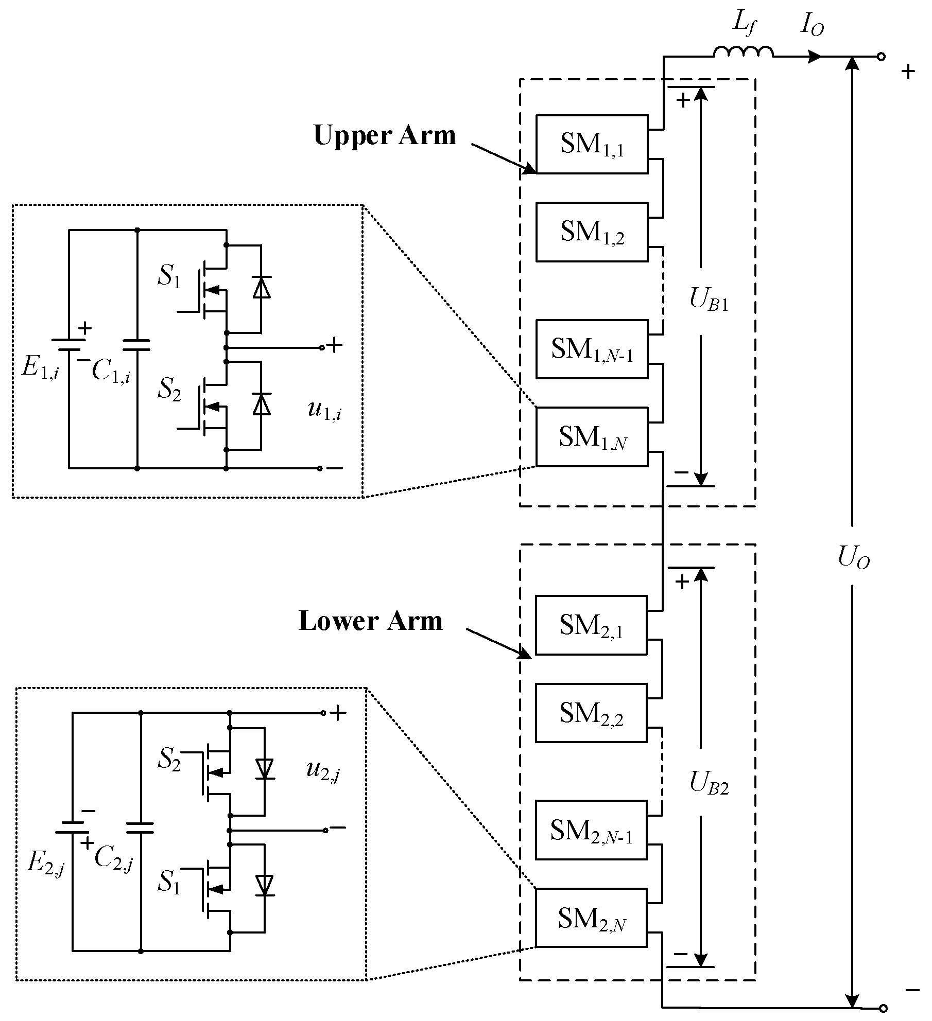
2.1. Topology of the Studied Multi-Level Converter

Figure 1 illustrates the topology of the modular multi-level half-bridge energy storage converter (MMH-ESC). The converter is composed of two sets of bridge arms connected in reverse series, with Lf being the filter inductance. Each SM contains a sub-battery pack E1/2,j, filter capacitor C1/2,j, and a half-bridge used for controlling the output. Table 1 presents the operational states of SMs. The half-bridge SM can be in either the connected state or the bypassed state with respect to the main circuit. Due to the different connection configurations, the upper arm SM (UA-SM) can provide a positive DC voltage output, while the lower arm SM (LA-SM) can provide a negative DC voltage output. By coordinating the operation of UA-SMs and LA-SMs, a stepped AC voltage can be generated. Assuming that the number of bridge arm SMs is N, each bridge arm can output up to N + 1 levels, and the maximum number of output levels of the converter is 2N + 1. When N = 4, the approximate sinusoidal voltage output is depicted in Figure 2.

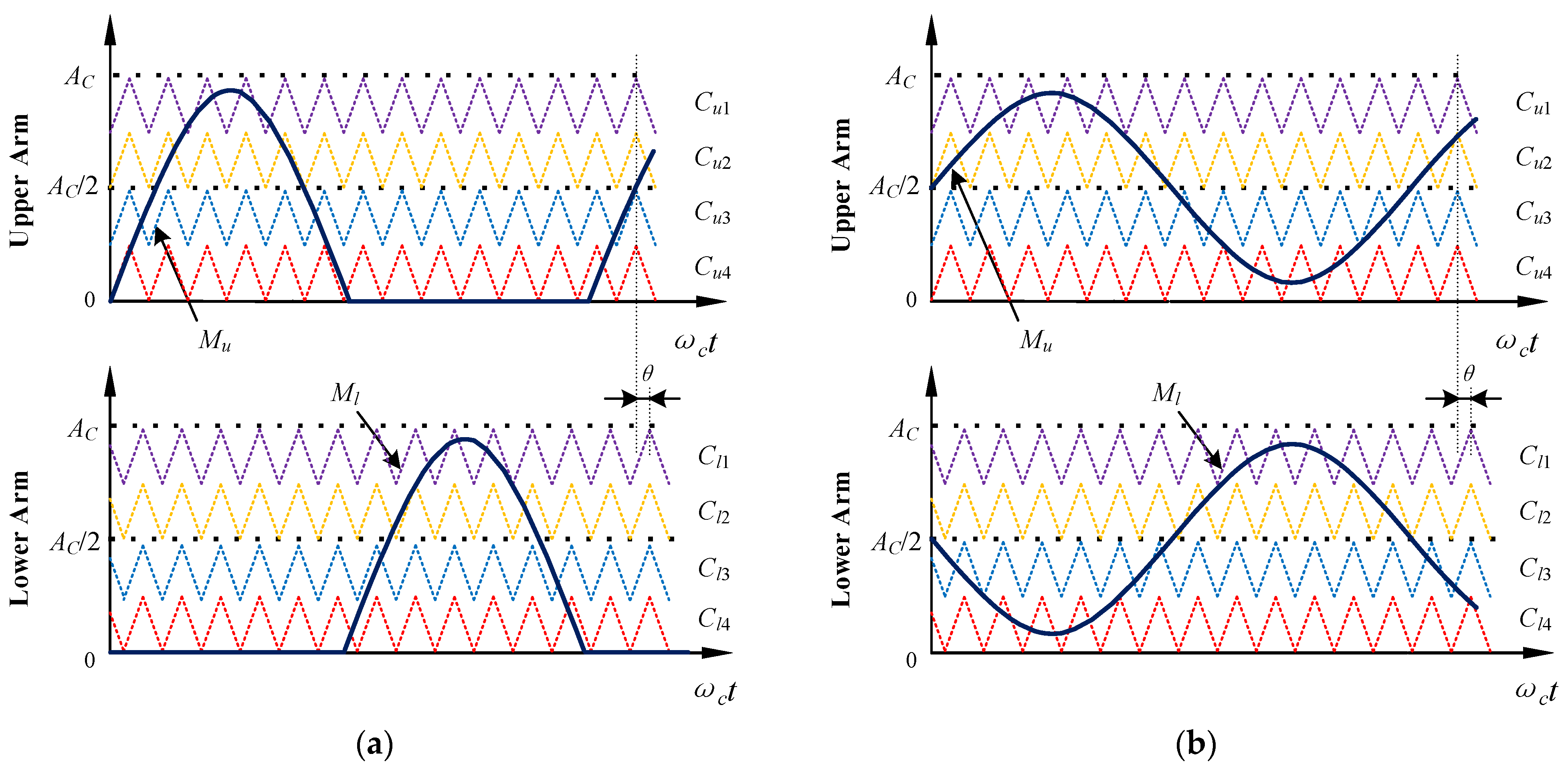
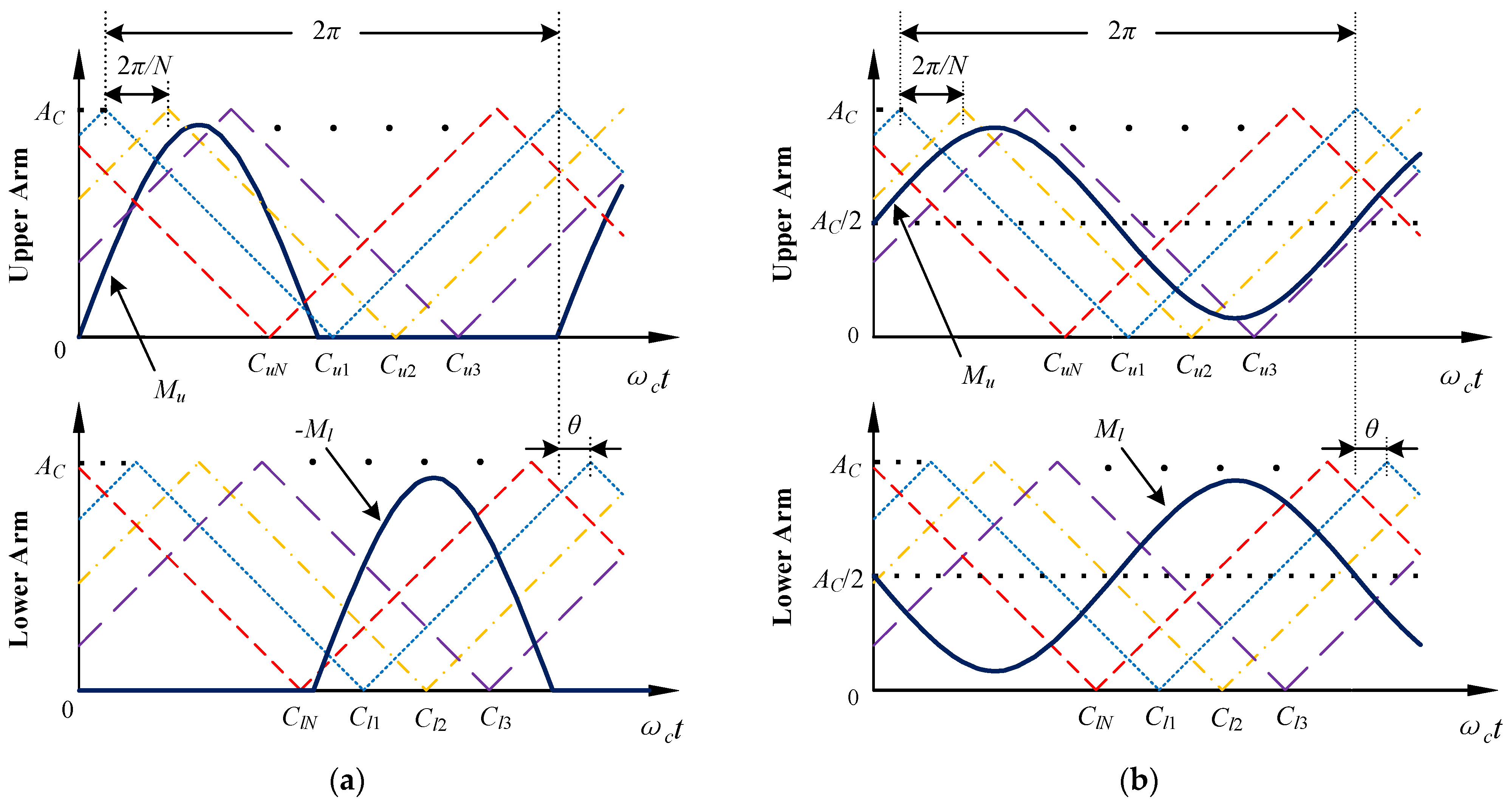
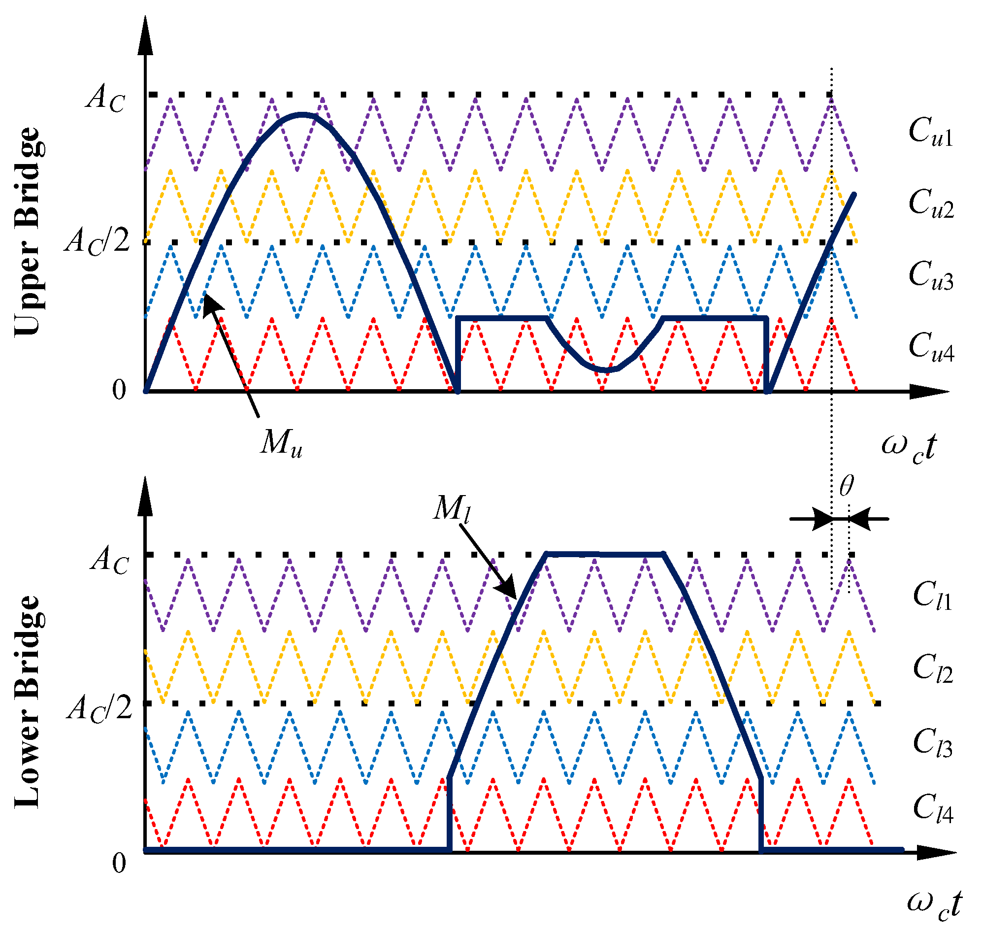
2.2. Pulse Width Modulation Mode

The main PWM methods for multi-level converters include the nearest level modulation (NLM), space vector PWM (SVPWM), LS-PWM, and PS-PWM. The NLM approximates the target output voltage using a stepped output voltage. The switching frequency and losses are low under NLM. However, it results in higher harmonic content for fewer SMs. So, this method is usually used when the number of SMs is large. SVPWM has a high voltage utilization rate but is more complex to implement. Both LS-PWM and PS-PWM have low output harmonics. The operating time of the switches under the LS-PWM is concentrated. The biggest advantage of the PS-PWM is the high equivalent switching frequency, which means that the frequency of each switch can be lower. When there are fewer SMs, LS-PWM and PS-PWM are commonly used modulation methods for multi-level converters.
Each carrier has a different level within LS-PWM. For the topology studied in this paper, the commonly used LS-PWM is illustrated in Figure 3 when N = 4. The output AC voltage is achieved by the coordination of the upper arm (UA) and lower arm (LA). The mode where the UA outputs a positive half-wave and the LA outputs a negative half-wave is called the sine half-wave cross level-shifted PWM (SHCLS-PWM), as shown in Figure 3a. The mode where each bridge arm carries half of the AC current is called dual carrier cross level-shifted PWM (DCCLS-PWM), as shown in Figure 3b. The amplitude of each carrier is 1, where Ac is numerically equal to the SM number in one bridge arm, Mu and Ml are the modulation waves for the UA and LA, respectively. Under the SHCLS-PWM, each bridge arm works separately. When a UA-SM is in the on state, no LA-SM is connected to the main circuit. So, there is no energy exchange between the two bridge arms. Under the DCCLS-PWM, SMs in both bridge arms operate throughout the entire period. So, there exists an energy exchange between the UA and LA. The energy flow changes when the direction of the converter’s output current changes.
Under the PS-PWM, each carrier has the same level but with a phase difference. For the topology studied in this paper, the commonly used PS-PWM is illustrated in Figure 4. The modulation waves for the two types of PS-PWM are the same as those shown in Figure 3, but the carriers are replaced with triangular waves with an amplitude of Ac and a phase difference of 2π/N between each carrier. The phase-shifted carriers can increase the equivalent switching frequency of the converter, and the magnitude of the equivalent switching frequency is affected by the value of the phase difference θ between carriers of the UA and LA. After amplification and translation, the carrier and modulation waves of the DCCPS-PWM can be transformed into bipolar modulation forms [21].
Under the PS-PWM, the difference between the on and bypass times of each SM is small, which results in the relatively balanced usage of batteries. However, under the LS-PWM, due to the characteristics of the modulation wave as a unary function, the bottom carrier corresponding to the SMs always has more opportunities to connect to the main circuit. While the top carrier corresponding to the SMs has fewer chances to connect to the main circuit. This means that the bottom SMs participate in more energy exchange. When the entire bridge arm is in the charging or discharging state, it is evident that the charging and discharging amounts of each SM are unbalanced. This imbalance is unfavorable for the long-term operation of the converter. However, this characteristic can also be actively utilized for battery balancing control. Therefore, LS-PWM is the main focus of this paper.

2.3. Battery Balancing Control

Due to the inevitable process and usage differences, the batteries within the SM exhibit imbalanced charge states during operation. Without balancing control, an SM’s battery may reach its charging or discharging limits over prolonged operation, necessitating its disconnection from the main circuit, thus impacting the normal operation of the converter. Therefore, implementing battery balancing control for multi-level converters is highly necessary.
Bridge arm battery balancing control based on the LS-PWM often involves sorting the batteries. Each carrier corresponds to an SM. The basis for sorting can be either the terminal voltage or SOC of the batteries. The terminal voltage is easy to measure, while the SOC provides a more accurate reflection of battery capacity utilization. In this study, the SOC is adopted as the sorting criterion. When the controlled bridge arm outputs energy, the SMs with higher SOCs are given priority. Conversely, when absorbing energy from external sources, SMs with lower SOCs are given priority, gradually achieving SOC balance among all SMs during continuous operation.
Figure 5 presents the MATLAB/Simulink simulation results for the battery SOC balancing control of the SMs within both arms using SHCLS-PWM. The simulation model includes four SMs per arm. The rated voltage of each SM battery is 12 V, with a rated capacity of 1500 mAh, and the converter outputs a sine current with an amplitude of 4 A. The initial SOC of each SM battery is set to a different value. The SM batteries within the same arm can quickly reach a SOC equilibrium state after active balancing control. Figure 6 shows the simulation results of battery SOC balancing control based on the DCCLS-PWM under the same conditions. In this case, both arms have SMs working throughout the entire time period, and the SMs with low battery SOCs have the opportunity to absorb energy from the SMs with high battery SOCs in the other arm, thereby reducing the time required to reach an equilibrium state.

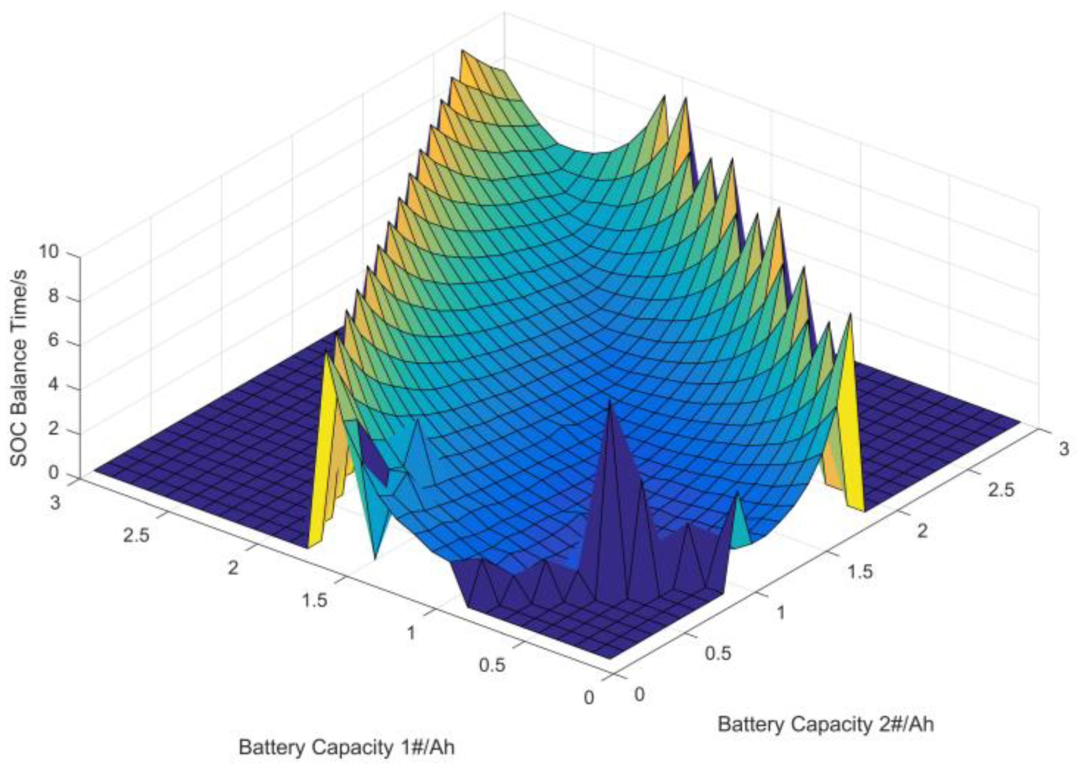
3. Analysis of Capacity Difference Tolerance

3.1. Calculation Method

Section 2.3 presents the simulation results of the equilibrium control when the SM battery parameters are identical. The rated voltage of each battery in the SM should be the same, in order to ensure the harmonic quality of the output voltage. However, the SOC equilibrium control based on the LS-PWM utilizes the characteristic that the charge and discharge of each battery are different and does not require a strict equality of the rated parameters for each group of batteries. With the rated voltage of the battery being kept the same, the SOC equilibrium strategy can allow for a certain degree of difference in battery capacity. This means that the multi-level converter studied in this paper has flexibility in the selection of energy storage batteries. This chapter will calculate and analyze the permissible degree of difference in battery capacity for the SOC equilibrium strategy involved.
When the output of the converter is sinusoidal AC, the initial modulation wave from the converter’s closed-loop control is expressed as:
M 0 t = M sin ω t
where M is the amplitude of the modulation wave, and ω is the angular frequency of the output voltage.
The MMH-ESC consists of two bridge arms connected in reverse series, and the modulation waves of the two bridge arms satisfy the following relationship:
M u t M l t = M 0 t
where Mu is the modulation wave of the UA, and Ml is the modulation wave of the LA.
The two LS-PWMs shown in Figure 3 represent two different arm modulation wave distributions. The modulation waves of the UA and LA in the SHCLS-PWM corresponding to Figure 3a are represented as follows:
M u 1 t = M sin ω t ,   2 k π / ω t 2 k + 1 π / ω 0 ,   2 k + 1 π / ω < t < 2 k + 2 π / ω
M l 1 t = 0 ,   2 k π / ω t 2 k + 1 π / ω M sin ω t ,   2 k + 1 π / ω < t < 2 k + 2 π / ω
where Mu1 is the modulation wave of the UA under the SHCLS-PWM, Ml1 is the modulation wave of the LA under the SHCLS-PWM, and k is an integer.
Similarly, the modulation waves of the UA and LA under the DCCLS-PWM corresponding to Figure 3b are represented as follows:
M u 2 t = A c 2 + M 2 sin ω t
M l 2 t = A c 2 M 2 sin ω t
where Mu2 is the modulation wave of the UA under the DCCLS-PWM, Ml2 is the modulation wave of the LA under the DCCLS-PWM, and Ac is the total amplitude of the carriers in the same arm. The carrier amplitude is set to 1 in this paper, so Ac is numerically equal to the SM number N.
The triangular carriers can be defined as:
C i t = 2 f c t + i 1   ,   k / f c t 2 k + 1 / 2 f c 2 f c t + i + 1   ,   2 k + 1 / 2 f c < t < k + 1 / f c
where Ci is the expression of the i th carrier from the bottom up, and i = 1, 2, …, N, fc is the carrier frequency.
The output current of the converter is defined as:
I d t = I sin ω t + φ
where I is the amplitude of the output current, and φ is the phase difference between the output current and the output voltage.
The SM has two states, connected and bypassed, and its output current can be expressed as:
I u i t = I d t ,   M u , 1 / 2 t C i t 0 ,   M u , 1 / 2 t < C i t
I l i t = I d t ,   M l , 1 / 2 t C i t 0 ,   M l , 1 / 2 t < C i t
where Iui is the output current of the i th UA-SM, and Ili is the output current of the i th LA-SM.
The amount of battery SOC change in one cycle can be calculated using the ampere-hour integration method:
Δ SOC u / l , i = 1 36 Q u / l , i 0 2 π / ω I u / l , i t d t
where Qu/l,i is the battery capacity of the i th SM in the UA or LA.
Figure 7 shows the output currents of UA-SMs using SHCLS-PWM for different phase differences between Id and M0. Where N = 4, I = 4 A, ω = 100π rad/s, the modulation ratio η = M/N = 1. Figure 8 shows the output current of UA-SMs using DCCLS-PWM under the same conditions as those shown in Figure 7. The currents shown in Figure 7 and Figure 8 are generated by the modulation shown in Figure 3 and used in the calculation in Equation (11). Because the load connected to a multi-level converter is often not purely resistive, there exists a phase difference between the output current and the modulation wave. Inductive load is the most common in real life, so this paper analyzes and studies them under inductive load.
The existence of phase differences causes each SM to have problems with output current commutation in one cycle, as shown in Figure 7 and Figure 8. SM 1# discharges the most power when outputting forward current. At the same time, the amount of charge is also the largest when the current is reversed. This affects the efficiency of the battery SOC balancing. Therefore, it is necessary to distinguish the direction of the output current and use different sort orders. The modified output currents are shown in Figure 9 and Figure 10. SM 1# discharges the most power while also charging the least.
The calculation of SOC change can be adjusted to:
Δ SOC u / l , i = 1 36 Q u / l , i k = 1 I u / l , i k Δ t > 0 2 π / ω / Δ t I u / l , i k Δ t Δ t + k = 1 I u / l , N i + 1 k Δ t < 0 2 π / ω / Δ t I u / l , N i + 1 k Δ t Δ t
where ∆t is the time step of the calculation process.

3.2. Calculation Results

The tolerance of battery SOC balancing control under the LS-PWM for battery capacity difference comes from the difference in current ampere-hour integration value:
S u / l , i = k = 1 I u / l , i k Δ t > 0 2 π / ω / Δ t I u / l , i k Δ t Δ t + k = 1 I u / l , N i + 1 k Δ t < 0 2 π / ω / Δ t I u / l , N i + 1 k Δ t Δ t
where Su/l,i is the current ampere-hour integration value of the i th SM in the UA or LA.
Figure 11 and Figure 12 show the normalized ampere-hour integral calculation. Where N = 10, I = 4 A, ω = 100π rad/s, fc = 10 kHz, and ∆t = 5 × 10⁻⁶ s. Figure 11 shows the calculation of the two modulation methods when the phase difference φ is fixed at 0.2 rad and the modulation ratio η changes from 0.1 to 1. SMs are sorted by charge or discharge amount. Based on the ampere-hour integral value of SM No. 1, the ampere-hour integration ratio of all remaining SMs is calculated. Similarly, Figure 12 shows the calculation of the two modulation methods when η is fixed at 1 and the phase difference φ changes from 0 rad to 0.9 rad. When the modulation ratio decreases or the phase difference increases, the imbalance in the integration value between SMs increases. The magnitude of the phase difference is determined by the load connected to the converter and generally cannot be actively adjusted. Appropriately reducing the modulation ratio can increase the imbalance of the ampere-hour integration value, which means that the tolerance of battery capacity difference is improved, which helps to achieve equalization control. However, there is a trade-off between the battery capacity difference tolerance and voltage utilization.
The amount of battery SOC change in a single cycle of each SM can be calculated when the ampere-hour integral value, the initial voltage, and the capacities of the SM are given. The SOC curve can be obtained according to the SOC balancing control strategy, and then the time taken to reach the balanced state can be recorded. At the same time, it can also determine whether the SOC curves are convergent.
Figure 13 shows examples of three sets of SOC curve calculation results under the SHCLS-PWM. The parameters are the same as those corresponding to Figure 5, expect for Q1,1, the battery capacity of SM1 in the UA. When Q1,1 = 1800 mAh, although there is a difference in battery capacity between the other three SMs, it can still reach a balanced state at about 7.9 s, as shown in Figure 13a. This scenario is verified in simulation, and the balancing time is about 7.8 s. The calculation error is 1.28%, which is within the allowable range. The running time of the calculation program is much less than that of the simulation, increasing the efficiency. When Q1,1 is 2500 mAh, the battery capacity of SM1 is too large, resulting in too little SOC change and divergence of SOC curves of the UA. Similarly, when Q1,1 is 700 mAh, the SM1′s battery capacity is too small, causing the SOC curve of the UA to diverge. Therefore, the capacity of the batteries needs to be within a reasonable range to ensure that the SOC balancing control based on the LS-PWM can be carried out.
The battery capacities of SMs in one bridge arm are changed and the time taken to reach the balance state is calculated to analyze the battery capacity difference tolerance of the LS-PWM-based battery SOC balancing strategy. The values of the calculation parameters are shown in Table 2. Where T is the upper limit of the balancing time, Q1,i is SM battery capacity, and SOCi,0 is the initial value of battery SOC.
Figure 14, Figure 15 and Figure 16 show the different calculation results under two modulation modes. In the case corresponding to Figure 14, Q1,2 and Q1,3 remain constant at 1500 mAh, while Q1,1 increases from 20 mAh to 3000 mAh. In the case corresponding to Figure 15, Q1,3 remains constant at 1500 mAh, while Q1,1 and Q1,2 increase from 20 mAh to 3000 mAh. The time taken to reach the SOC balanced state is recorded. If, at the time limit T, the sum of the absolute differences in battery SOCs still exceeds the set threshold, it is considered a failure of battery balancing, and the balancing time is recorded as 0. In the case corresponding to Figure 16, Q1,1, Q1,2, and Q1,3 increase from 20 mAh to 3000 mAh. It is challenging to display the balancing time when all three battery capacities are changing in a three-dimensional graph. Therefore, the data points that can achieve the equilibrium state within the specified time limit are plotted instead.
From Figure 14 and Figure 15, it can be observed that when the capacities of the batteries are similar, the time required to achieve equilibrium is shorter. However, when a battery has a significantly larger or smaller capacity than the other batteries, the balancing time increases, and even cases of SOC divergence may occur. Figure 11 and Figure 12 demonstrate the degrees of imbalance in the SM currents under two modulation methods. Due to the greater time that SMs are connected to the main circuit under the DCCLS-PWM than that under the SHCLS-PWM, there is more reverse current, resulting in a higher level of imbalance compared to the SHCLS-PWM. A higher degree of current imbalance indicates that this modulation method allows for greater tolerance of battery capacity differences, which can be visually observed in Figure 14, Figure 15 and Figure 16.

4. Optimization of Capacity Difference Tolerance

4.1. Modified Modulation

As analyzed in the previous section, the battery SOC balancing control using the DCCLS-PWM exhibits significantly higher tolerance for battery capacity differences compared to the SHCLS-PWM. This is because one bridge arm operates only during half of the cycle under the SHCLS-PWM, with the majority of that time having positive output currents from the SMs. Although it performs worse in terms of balancing control, the single direction of output current is more favorable for battery lifespan. At the same time, the unused half cycle in the SHCLS-PWM provides room for improvement.
Supposing there is a capacity mismatch between one SM in the UA and the other SMs in the converter, the originally zero half-wave of the modulation wave in the UA can be raised. By constructing an energy exchange between the UA and LA, the degree of imbalance in the UA’s output current can be increased, thereby enhancing the tolerance for battery capacity differences. The optimized schematic diagram of the SHCLS-PWM is shown in Figure 17. The originally zero half-wave is raised by one carrier height. To ensure that the output voltage of the converter remains unchanged, as in Equation (2), the modulation wave of the lower bridge arm also needs to be correspondingly raised.
The modulation waves of the UA and LA in the modified SHCLS-PWM c are represented as follows:
M u t = M sin ω t ,   2 k π / ω t 2 k + 1 π / ω L ,   2 k + 1 π / ω < t < 2 k + 2 π / ω
M l t = 0 ,   2 k π / ω t 2 k + 1 π / ω L M sin ω t   ,   2 k + 1 π / ω < t < 2 k + 2 π / ω
where L is the height at which the half-wave was lifted from 0.
The above equations are correct when the modulation waves do not exceed the sum of the carrier amplitudes, that is, L + M ≤ N (the carrier amplitude is set to 1 in this paper). When L + M > N, overmodulation occurs in the lower bridge arm. To ensure that the output voltage remains unchanged, it is necessary to change the UA synchronously. The modulation wave in this case can be represented as follows. Figure 17 precisely depicts the modulation waves when L = 1 and L + M > N.
M u t = M sin ω t ,   2 k π / ω t 2 k + 1 π / ω L ,   2 k + 1 π / ω < t < 2 k + 1 π + arcsin N L M / ω M sin ω t + N ,   2 k + 1 π + arcsin N L M / ω t 2 k + 2 π arcsin N L M / ω L ,   2 k + 2 π arcsin N L M / ω < t < 2 k + 2 π / ω
M l t = 0 ,   2 k π / ω t 2 k + 1 π / ω L M sin ω t   ,   2 k + 1 π / ω < t < 2 k + 1 π + arcsin N L M / ω N   ,   2 k + 1 π + arcsin N L M / ω t 2 k + 2 π arcsin N L M / ω L M sin ω t   ,   2 k + 2 π arcsin N L M / ω < t < 2 k + 2 π / ω

4.2. Optimized Results

An analysis of the tolerance for battery capacity differences in the modified SHCLS-PWM is conducted in the same environment as described in Section 3.2. The parameters used in the calculation are shown in Table 2. Figure 18, Figure 19 and Figure 20 present the results of the equilibrium control when the battery capacities change for one, two, and three SMs, respectively. Figure 18 compares the SOC balancing time between the improved SHCLS-PWM and the two original modulation methods. It can be observed that the improved modulation strategy exhibits a significantly greater capacity difference margin compared to the SHCLS-PWM and DCCLS-PWM. Particularly, even when the battery capacity of one SM is much lower than that of the other SMs, the modified modulation strategy still achieves SOC balance in the bridge arm. It is attributed to the increased imbalance in the output current of the SM due to the added half-cycle current. This implies that when a battery in one SM of the converter becomes unusable unexpectedly, it can be temporarily replaced with a small-capacity backup battery of an equivalent rated voltage, which improves the fault tolerance capability and reduces the cost of backup components.
As shown in Figure 18, the tolerance for capacity differences and the SOC balancing speed are both better when L = 2 compared to L = 1. However, L = 2 means that two SMs are connected to the main circuit during the half cycle where they should have been bypassed. This disrupts the power balance between the UA and LA and is not suitable for long-term operation in this mode. When comparing Figure 19 with Figure 15 and Figure 20 with Figure 16, it can be observed that the modified SHCLS-PWM has already shown significant improvements in terms of the tolerance for capacity differences at L = 1. Therefore, there is no need to choose a larger value for L to further sacrifice the power balance between the two bridge arms.

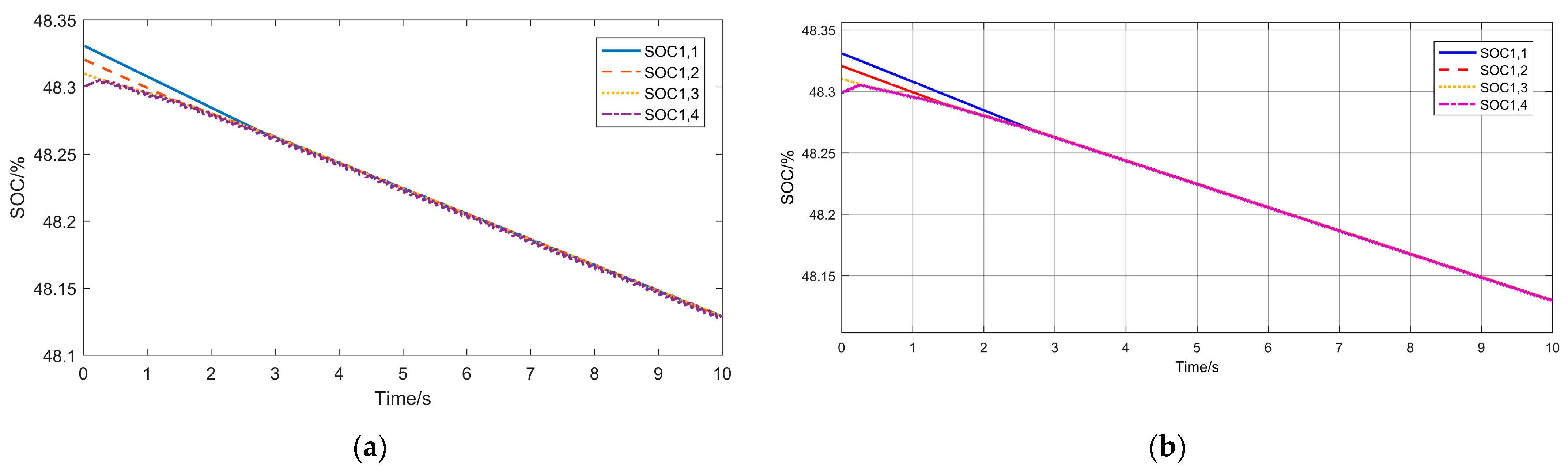
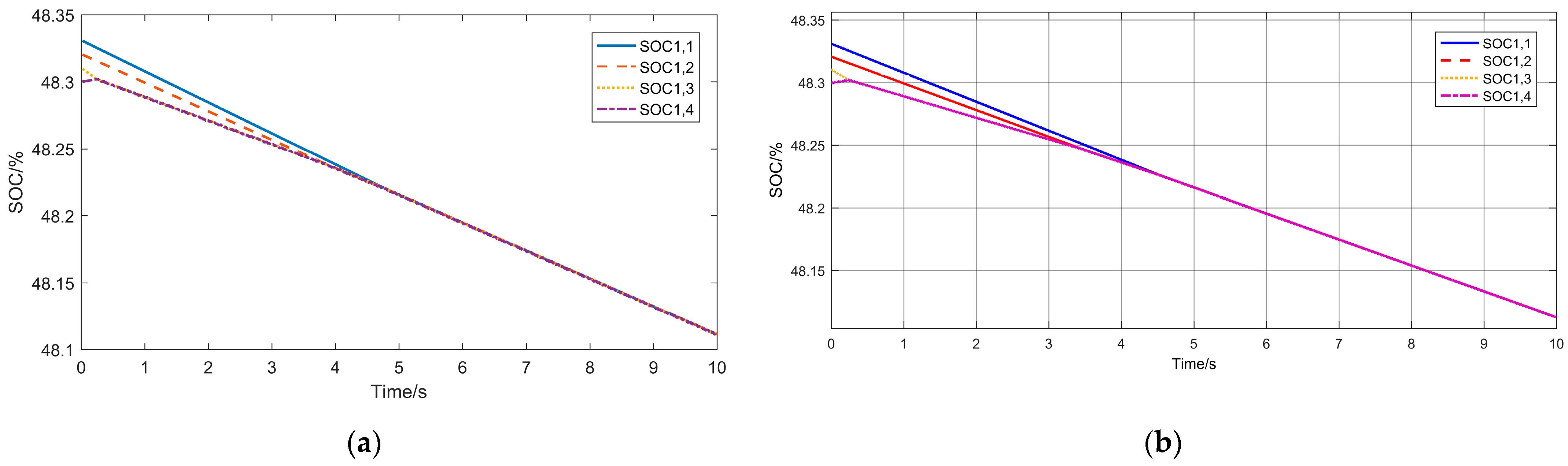
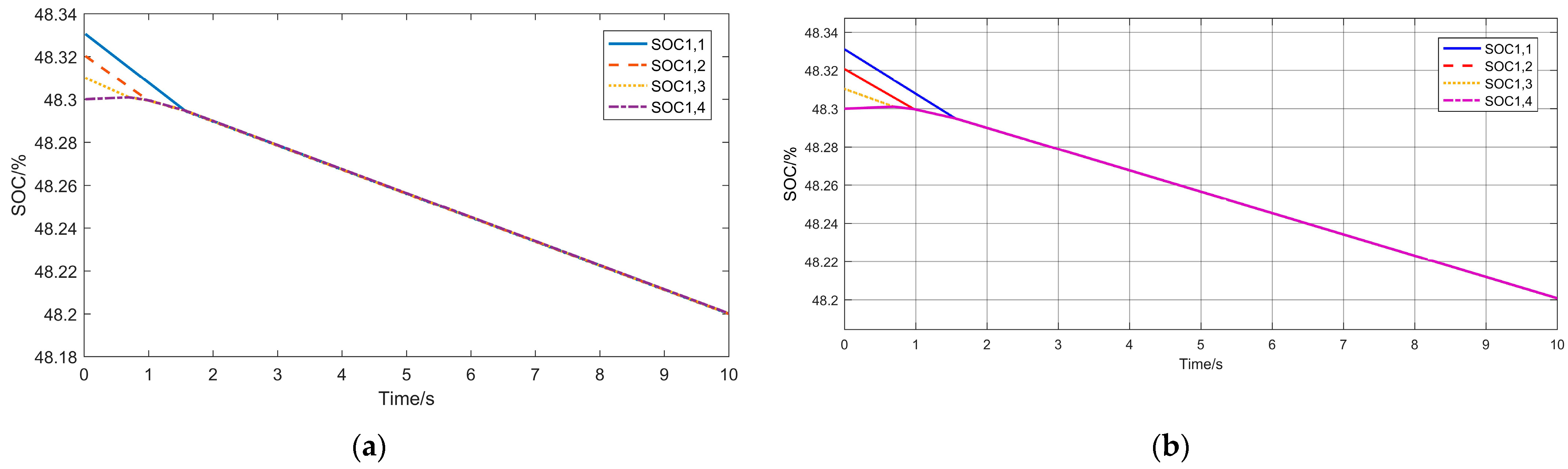
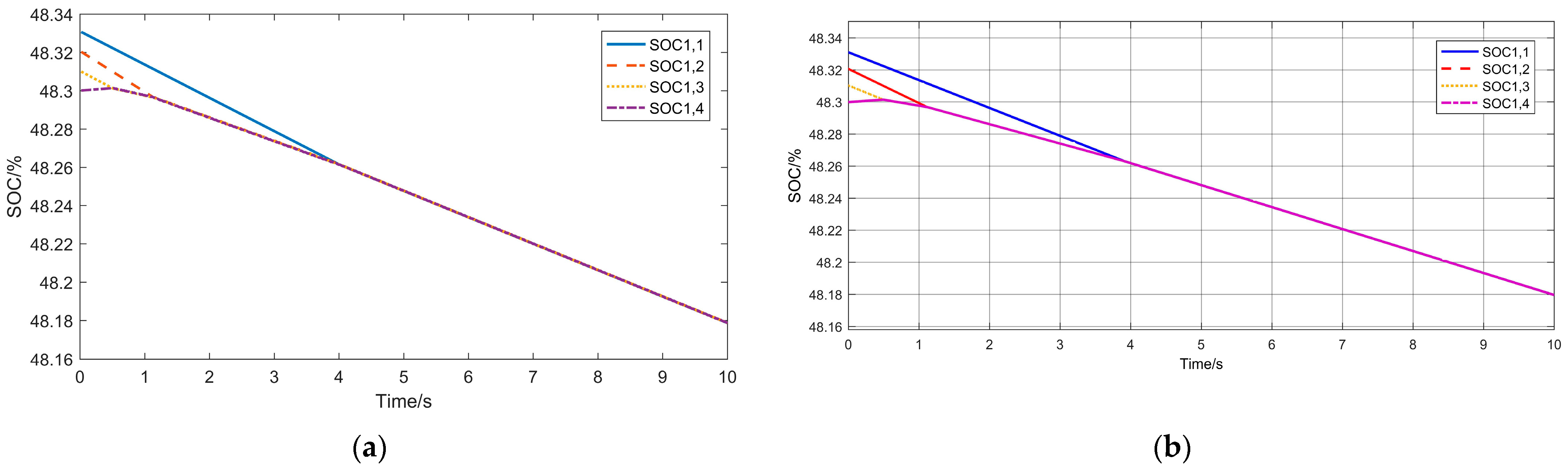
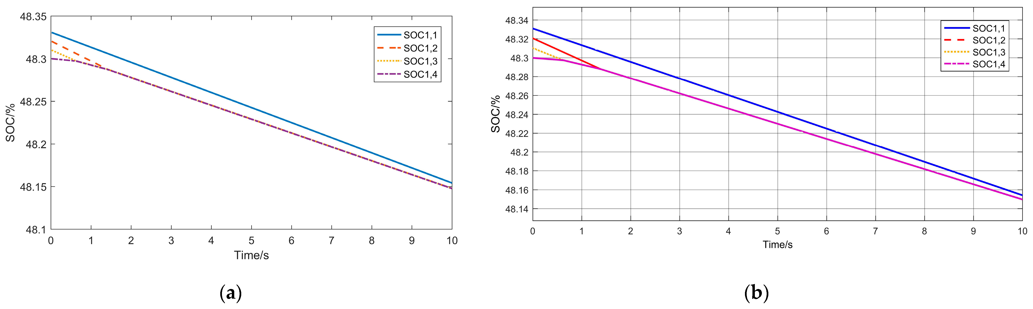
4.3. Simulation and Verification

Section 2.3 shows the MATLAB/Simulink simulation results for the battery SOC balancing control of the SMs within both arms using SHCLS-PWM and DCCLS-PWM. In addition, as mentioned in Section 3.2, the balancing time calculation error of the corresponding case in Figure 13a is 1.28%. This section will introduce the simulation verification scheme, and further verify the proposed calculation method and modified modulation method through the MATLAB/Simulink simulation. Figure 21 shows the framework of the simulation verification. The MMH-ESC is connected to a controlled current source (CCS) to control the converter output current. All parameters are set according to Table 2 for simulation verification, including current amplitude and phase, modulation wave amplitude, battery capacities, initial SOCs, etc.
Eight cases with different values of battery capacity and different modulation methods are conducted, and the SOC calculation result curves and SOC simulation result curves of the corresponding cases are given in Figure 22, Figure 23, Figure 24, Figure 25, Figure 26, Figure 27, Figure 28 and Figure 29. The time taken to reach the SOC balanced state and the calculation errors are recorded in Table 3.
  • Case 1: Q1,1 = Q1,2 = Q1,3 = Q1,4 =1500 mAh, under the modified SHCLS-PWM, L = 1;
  • Case 2: Q1,1 = Q1,2 = Q1,3 = 1500 mAh, Q1,4 = 200 mAh, under the modified SHCLS-PWM, L = 1;
  • Case 3: Q1,1 = Q1,2 = 1500 mAh, Q1,3 = 800 mAh, Q1,4 = 500 mAh, under the modified SHCLS-PWM, L = 1;
  • Case 4: Q1,1 = Q1,2 = 1500 mAh, Q1,3 = 2000 mAh, Q1,4 = 3000 mAh, under the modified SHCLS-PWM, L = 1;
  • Case 5: Q1,1 = 2000 mAh, Q1,2 = Q1,3 = Q1,4 = 1500 mAh, under the modified SHCLS-PWM, L = 1;
  • Case 6: Q1,1 = 2000 mAh, Q1,2 = Q1,3 = Q1,4 = 1500 mAh, under the modified SHCLS-PWM, L = 2;
  • Case 7: Q1,1 = 2000 mAh, Q1,2 = Q1,3 = Q1,4 = 1500 mAh, under the SHCLS-PWM;
  • Case 8: Q1,1 = 2000 mAh, Q1,2 = Q1,3 = Q1,4 = 1500 mAh, under the DCCLS-PWM.
Among the eight cases shown in Figure 22, Figure 23, Figure 24, Figure 25, Figure 26, Figure 27, Figure 28 and Figure 29, the changing trends of all SOC curve calculation results are the same as the simulation results. The calculation errors of the balancing time are all within 5%. When the capacity of all batteries is not less than 1500 mAh, the calculation results are more accurate, with an error of less than 3%. When a certain battery capacity value is small, its SOC and terminal voltage change amplitude is large, affecting the calculation accuracy. Cases 5–8 compare the balancing control effects of different modulation methods when the battery capacities are the same. The results correspond to Figure 18. At this time, neither the SHCLS-PWM nor the DCCLS-PWM can balance the SOCs within 10 s. The improved modulation method has been verified to improve the tolerance of battery capacity differences.

5. Conclusions

This paper focuses on a multi-level converter topology and analyzes and compares two pulse width modulation methods for their tolerance to capacity differences in SMs. The calculations are performed, and the modified modulation method with the higher tolerance is presented. The main results can be summarized as follows:
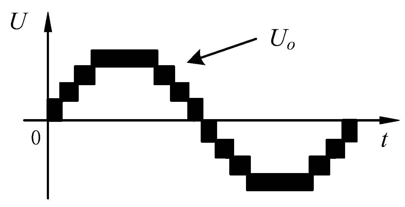
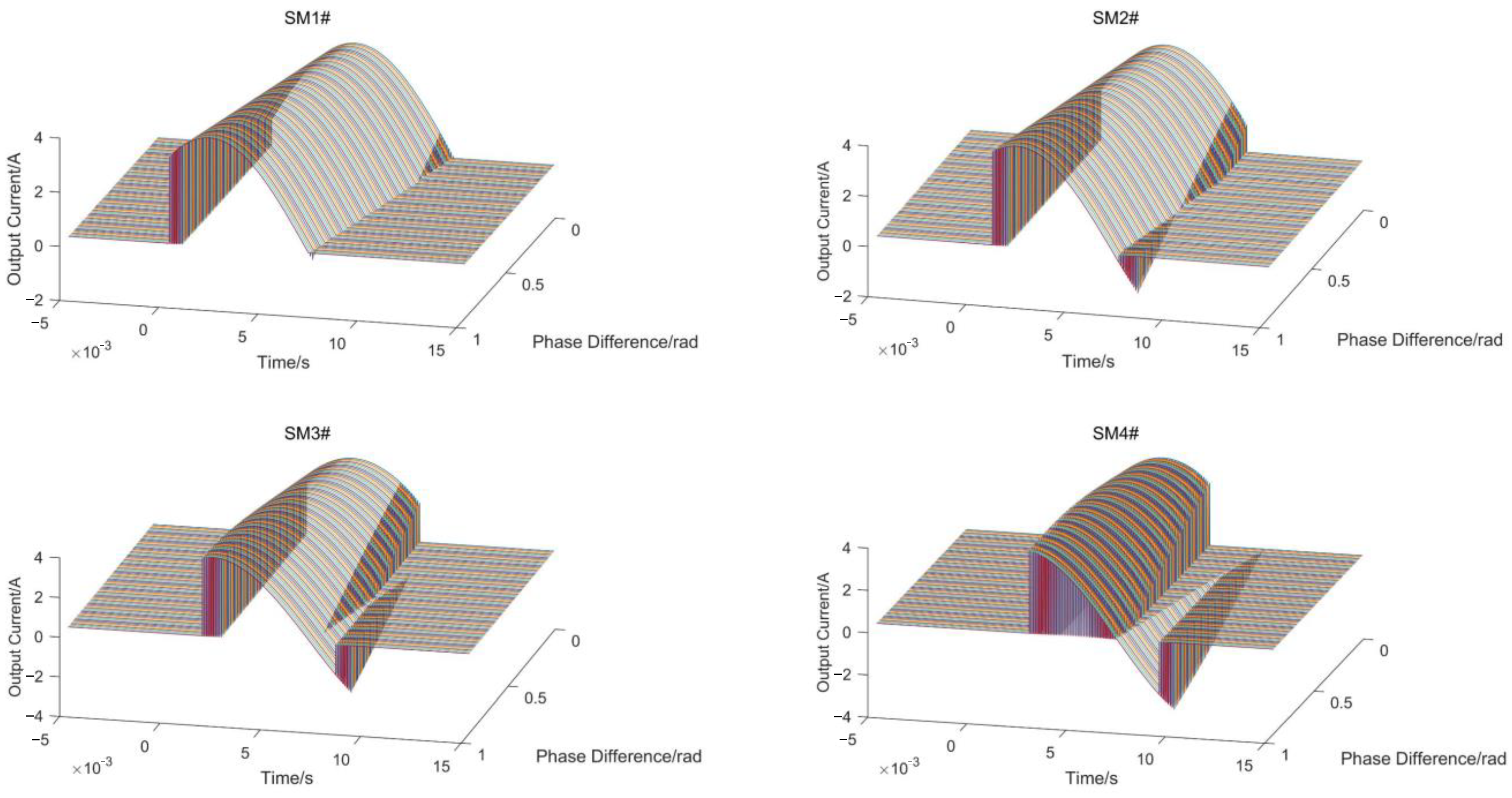
  • MMH-ESC consists of two groups of reverse-connected half-bridges. Under the SHCLS-PWM, the bridge arms generate positive and negative half-wave AC voltages, respectively. In contrast, under the DCCLS-PWM, the bridge arms share the AC voltage to be output, resulting in each SM operating throughout the entire cycle. This leads to greater variation in output currents among SMs under the DCCLS-PWM.
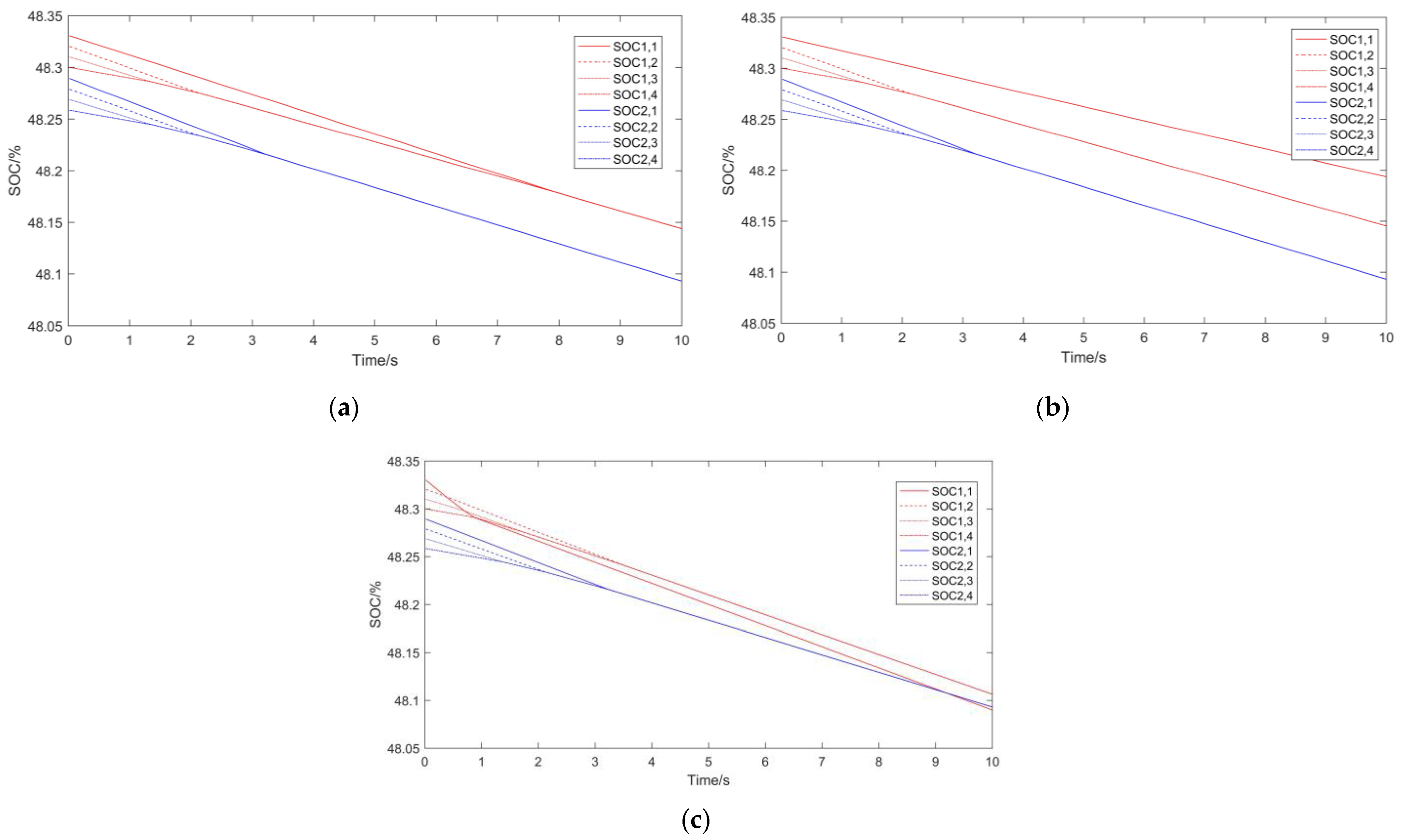
  • In the SM battery SOC balancing control strategy based on the LS-PWM, the carriers are arranged according to the battery SOCs. By utilizing the imbalance in battery charge and discharge under the LS-PWM, active SOC balancing control is performed. After obtaining the measured load current values, the SOC change rate for the given battery capacities can be calculated to determine if equilibrium can be achieved. If possible, the time required to reach the balanced state can be predicted through calculations.
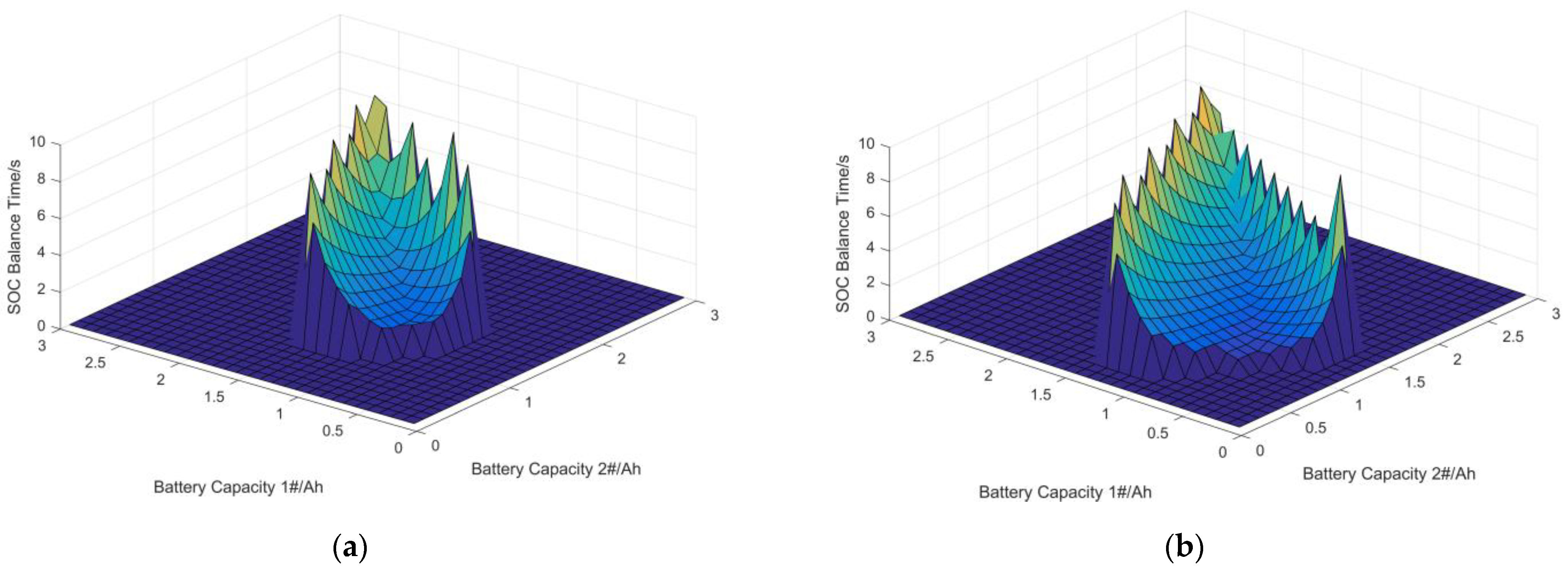
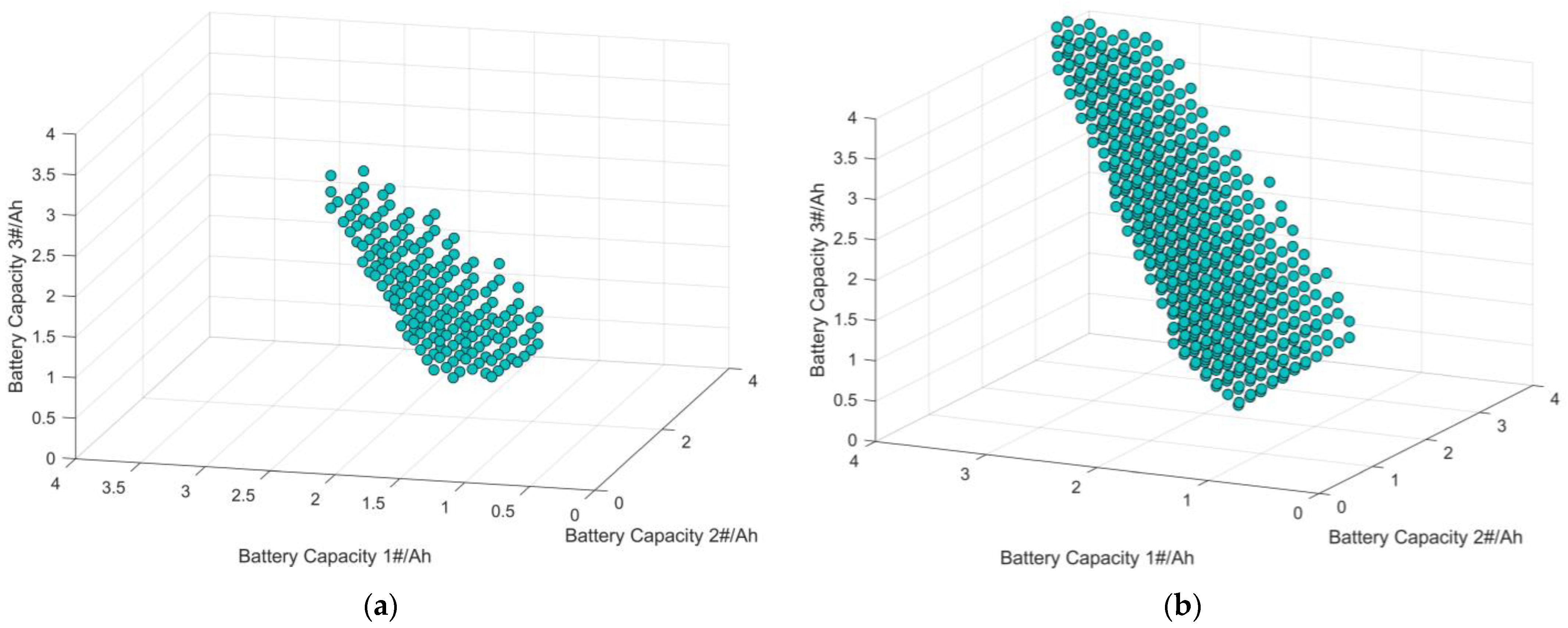
  • Studying and calculating the tolerance for capacity differences among batteries allows for determining the range of battery capacity values that can maintain a balanced state, without the need to restrict all batteries to the same capacity. This enhances flexibility in battery configuration and utilization.
  • Finally, by combining the characteristics of the two existing modulation methods and aiming to improve capacity tolerance, a new bridge arm modulation wave allocation method is proposed. This method significantly expands the range of SM battery capacity selection and provides a high-tolerance modulation method for the converter under extreme or even fault conditions.

Author Contributions

Conceptualization, Y.P. and Q.W.; methodology, Y.P.; software, Y.P.; validation, Y.P. and Q.W.; formal analysis, Q.W.; investigation, Q.W.; resources, Y.P.; data curation, Y.P.; writing—original draft preparation, Y.P.; writing—review and editing, Q.W.; visualization, Y.P.; supervision, Q.W. and G.B.; project administration, Q.W.; funding acquisition, Q.W. All authors have read and agreed to the published version of the manuscript.

Funding

This work was supported by Key Laboratory of Control of Power Transmission and Conversion (SJTU), Ministry of Education under project 2023AB01 and by the National Natural Science Foundation of China under projects 52177171.

Institutional Review Board Statement

Not applicable.

Informed Consent Statement

Not applicable.

Data Availability Statement

The authors confirm that the data supporting the findings of this study are available within the article.

Acknowledgments

The authors would like to thank the Jiangsu Provincial Key Laboratory of Smart Grid Technology and Equipment, Southeast University for their help in this research.

Conflicts of Interest

The authors declare no conflict of interest.

References

  1. Breyer, C.; Khalili, S.; Bogdanov, D.; Ram, M.; Oyewo, A.S.; Aghahosseini, A.; Sovacool, B.K. On the history and future of 100% renewable energy systems research. IEEE Access 2022, 10, 78176–78218. [Google Scholar] [CrossRef]
  2. Li, X.; Wang, S. Energy management and operational control methods for grid battery energy storage systems. CSEE J. Power Energy Syst. 2021, 7, 1026–1040. [Google Scholar]
  3. Khalid, M.R.; Khan, I.A.; Hameed, S.; Asghar, M.S.J.; Ro, J.-S. A comprehensive review on structural topologies, power levels, energy storage systems, and standards for electric vehicle charging stations and their impacts on grid. IEEE Access 2021, 9, 128069–128094. [Google Scholar] [CrossRef]
  4. Fang, J.; Blaabjerg, F.; Liu, S.; Goetz, S.M. A review of multilevel converters with parallel connectivity. IEEE Trans. Power Electron. 2021, 36, 12468–12489. [Google Scholar] [CrossRef]
  5. Yuan, X. Ultimate generalized multilevel converter topology. IEEE Trans. Power Electron. 2021, 36, 8634–8639. [Google Scholar] [CrossRef]
  6. Liu, Y.; Peng, F.Z. A modular multilevel converter with self-voltage balancing part II: Y-matrix modulation. IEEE J. Emerg. Sel. Top. Power Electron. 2020, 8, 1126–1133. [Google Scholar] [CrossRef]
  7. Zhang, G.; Yu, J. Open-circuit fault diagnosis for cascaded H-bridge multilevel inverter based on LS-PWM technique. CPSS Trans. Power Electron. Appl. 2021, 6, 201–208. [Google Scholar] [CrossRef]
  8. Jin, Y.; Xiao, Q.; Pou, J.; Jia, H.; Ji, Y.; Teodorescu, R.; Blaabjerg, F. A novel fault-tolerant operation approach for the modular multilevel converter-based STATCOM with the enhanced operation capability. IEEE J. Emerg. Sel. Top. Power Electron. 2022, 10, 5541–5552. [Google Scholar] [CrossRef]
  9. Liu, J.; Dong, D. A flying capacitor hybrid modular multilevel converter with reduced number of submodules and power losses. IEEE Trans. Ind. Electron. 2023, 70, 3293–3302. [Google Scholar] [CrossRef]
  10. Tashakor, N.; Iraji, F.; Goetz, S.M. Low-frequency scheduler for optimal conduction loss in series/parallel modular multilevel converters. IEEE Trans. Power Electron. 2022, 37, 2551–2561. [Google Scholar] [CrossRef]
  11. Ma, Z.; Gao, F.; Gu, X.; Li, N.; Wu, Q.; Wang, X.; Wang, X. Multilayer SOH equalization scheme for MMC battery energy storage system. IEEE Trans. Power Electron. 2020, 35, 13514–13527. [Google Scholar] [CrossRef]
  12. Guo, P.; Xu, Q.; Yue, Y.; Ma, F.; He, Z.; Luo, A.; Guerrero, J. Analysis and control of modular multilevel converter with split energy storage for railway traction power conditioner. IEEE Trans. Power Electron. 2020, 35, 1239–1255. [Google Scholar] [CrossRef]
  13. Deng, F.; Lü, Y.; Liu, C.; Heng, Q.; Yu, Q.; Zhao, J. Overview on submodule topologies, modeling, modulation, control schemes, fault diagnosis, and tolerant control strategies of modular multilevel converters. Chin. J. Electr. Eng. 2020, 6, 1–21. [Google Scholar] [CrossRef]
  14. Vasiladiotis, M.; Rufer, A. Analysis and control of modular multilevel converters with integrated battery energy storage. IEEE Trans. Power Electron. 2015, 30, 163–175. [Google Scholar] [CrossRef]
  15. Quraan, M.; Yeo, T.; Tricoli, P. Design and control of modular multilevel converters for battery electric vehicles. IEEE Trans. Power Electron. 2016, 1, 507–517. [Google Scholar] [CrossRef]
  16. Rahman, S.; Meraj, M.; Iqbal, A.; Reddy, B.P.; Khan, I. A combinational level-shifted and phase-shifted PWM technique for symmetrical power distribution in CHB inverters. IEEE J. Emerg. Sel. Top. Power Electron. 2021, 11, 932–941. [Google Scholar] [CrossRef]
  17. Meraj, M.; Rahman, S.; Iqbal, A.; Al Emadi, N. Novel level shifted PWM technique for unequal and equal power sharing in quasi Z-source cascaded multilevel inverter for PV systems. IEEE J. Emerg. Sel. Top. Power Electron. 2021, 9, 937–948. [Google Scholar] [CrossRef]
  18. Eroglu, F.; Kurtoglu, M.; Vural, A.M. Bidirectional DC-DC converter based multilevel battery storage systems for electric vehicle and large-scale grid applications: A critical review considering different topologies, state-of-charge balancing and future trends. IET Renew. Power Gener. 2021, 15, 915–938. [Google Scholar] [CrossRef]
  19. Busquets-Monge, S.; Filba-Martinez, A.; Alepuz, S.; Nicolas-Apruzzese, J.; Luque, A.; Conesa-Roca, A.; Bordonau, J. Multi-battery-fed neutral-point-clamped DC–AC converter with SOC balancing control to maximize capacity utilization. IEEE Trans. Ind. Electron. 2020, 67, 16–27. [Google Scholar] [CrossRef]
  20. Chen, P.; Xiao, F.; Liu, J.; Zhu, Z.; Ren, Q. Unbalanced operation principle and fast balancing charging strategy of a cascaded modular multilevel converter–bidirectional DC–DC converter in the shipboard applications. IEEE Trans. Transp. Electrif. 2020, 6, 1265–1278. [Google Scholar] [CrossRef]
  21. Ahmad, A.B.; Ooi, C.A.; Ishak, D. State-of-charge balancing control for optimal cell utilization of a grid-scale three-phase battery energy storage system using hybrid modular multilevel converter topology without redundant cells. IEEE Access 2021, 9, 53920–53935. [Google Scholar] [CrossRef]
  22. Bi, K.; Yang, W.; Xu, D.; Yan, W. Dynamic SOC balance strategy for modular energy storage system based on adaptive droop control. IEEE Access 2020, 8, 41418–41431. [Google Scholar] [CrossRef]
  23. Fatih, E.; Mehmet, K.; Ahmet, E.; Ahmet, M.V. A novel adaptive state-of-charge balancing control scheme for cascaded H-bridge multilevel converter based battery storage systems. ISA Trans. 2023, 135, 339–354. [Google Scholar]
  24. Wang, S.; Du, M.; Lu, L.; Xing, W.; Sun, K.; Ouyang, M. Multilevel energy management of a DC microgrid based on virtual-battery model considering voltage regulation and economic optimization. IEEE J. Emerg. Sel. Top. Power Electron. 2021, 9, 2881–2895. [Google Scholar] [CrossRef]
  25. Zheng, Z.; Wang, K.; Xu, L.; Li, Y. A hybrid cascaded multilevel converter for battery energy management applied in electric vehicles. IEEE Trans. Power Electron. 2014, 29, 3537–3546. [Google Scholar] [CrossRef]
  26. Yu, J.; Zhang, G.; Peng, M.; Song, D.; Liu, M. Power-matching based SOC balancing method for cascaded H-bridge multilevel inverter. CPSS Trans. Power Electron. Appl. 2020, 5, 352–363. [Google Scholar] [CrossRef]
  27. Tashakor, N.; Keshavarzi, D.; Iraji, F.; Banana, S.; Goetz, S. Voltage estimation in combination with level-adjusted phase-shifted-carrier modulation for sensorless balancing of diode-clamped modular multilevel converters. IEEE Trans. Power Electron. 2023, 38, 4267–4278. [Google Scholar] [CrossRef]
  28. Ye, M.; Peng, R.; Tong, Z.; Chen, Z.; Miao, Z. A generalized scheme with linear power balance and uniform switching loss for asymmetric cascaded H-bridge multilevel inverters. IEEE Trans. Power Electron. 2022, 37, 2719–2730. [Google Scholar] [CrossRef]
  29. Wang, W.; Ma, K.; Cai, X. Efficient capacitor voltage balancing method for modular multilevel converter under carrier-phase-shift pulse width modulation. IEEE Trans. Power Electron. 2021, 36, 1553–1562. [Google Scholar] [CrossRef]
  30. Wang, Q.; Hong, Z.; Deng, F.; Cheng, M.; Buja, G. A novel diagnosis strategy for switches with common electrical faults in modular multi-level half-bridge energy storage converter. IEEE Trans. Power Electron. 2023, 38, 5335–5346. [Google Scholar] [CrossRef]
Figure 1. Topology of MMH-ESC.
Energies 16 07789 g001
Figure 2. AC output voltage when N = 4.
Energies 16 07789 g002
Figure 3. Schematic diagram of the LS-PWM: (a) SHCLS-PWM; (b) DCCLS-PWM.
Energies 16 07789 g003
Figure 4. Schematic diagram of the PS-PWM: (a) SHCPS-PWM; (b) DCCPS-PWM.
Energies 16 07789 g004
Figure 5. Battery SOC waves under the SHCLS-PWM.
Energies 16 07789 g005
Figure 6. Battery SOC waves under the DCCLS-PWM.
Energies 16 07789 g006
Figure 7. Output current of UA-SMs under the SHCLS-PWM.
Energies 16 07789 g007
Figure 8. Output current of UA-SMs under the DCCLS-PWM.
Energies 16 07789 g008
Figure 9. Modified output current of UA-SMs under the SHCLS-PWM.
Energies 16 07789 g009
Figure 10. Modified output current of UA-SMs under the DCCLS-PWM.
Energies 16 07789 g010
Figure 11. Normalized ampere-hour integral calculation with different modulation ratios: (a) under the SHCLS-PWM; (b) under the DCCLS-PWM.
Energies 16 07789 g011
Figure 12. Normalized ampere-hour integral calculation with different phase differences: (a) under the SHCLS-PWM; (b) under the DCCLS-PWM.
Energies 16 07789 g012
Figure 13. Calculated SOC curves: (a) Q1,1 = 1800 mAh; (b) Q1,1 = 2500 mAh; (c) Q1,1 = 700 mAh.
Energies 16 07789 g013
Figure 14. SOC balancing time when one SM battery capacity changes: (a) under the SHCLS-PWM; (b) under the DCCLS-PWM.
Energies 16 07789 g014
Figure 15. SOC balancing time when two SM battery capacities change: (a) under the SHCLS-PWM; (b) under the DCCLS-PWM.
Energies 16 07789 g015
Figure 16. SOC balance condition when three SM battery capacities change: (a) under the SHCLS-PWM; (b) under the DCCLS-PWM.
Energies 16 07789 g016
Figure 17. Schematic diagram of the modified SHCLS-PWM when L = 1 and L + M > N.
Energies 16 07789 g017
Figure 18. SOC balancing time when one SM battery capacity changes under different modulations.
Energies 16 07789 g018
Figure 19. SOC balancing time when two SM battery capacities change under the modified SHCLS-PWM, L = 1.
Energies 16 07789 g019
Figure 20. SOC balance condition when three SM battery capacities change under the modified SHCLS-PWM, L = 1.
Energies 16 07789 g020
Figure 21. Framework of the simulation verification.
Energies 16 07789 g021
Figure 22. SOC curves in Case 1: (a) calculation result; (b) simulation result.
Energies 16 07789 g022
Figure 23. SOC curves in Case 2: (a) calculation result; (b) simulation result.
Energies 16 07789 g023
Figure 24. SOC curves in Case 3: (a) calculation result; (b) simulation result.
Energies 16 07789 g024
Figure 25. SOC curves in Case 4: (a) calculation result; (b) simulation result.
Energies 16 07789 g025
Figure 26. SOC curves in Case 5: (a) calculation result; (b) simulation result.
Energies 16 07789 g026
Figure 27. SOC curves in Case 6: (a) calculation result; (b) simulation result.
Energies 16 07789 g027
Figure 28. SOC curves in Case 7: (a) calculation result; (b) simulation result.
Energies 16 07789 g028
Figure 29. SOC curves in Case 8: (a) calculation result; (b) simulation result.
Energies 16 07789 g029
Table 1. Operational states of SMs in each bridge arm.
S1 StateS2 StateUA-SM Output u1,iLA-SM Output u2,iSM Working State
10E1,iE2,iConnected
0100Bypassed
Table 2. Values of the calculation parameters.
ParameterValueParameterValue
N4Q1,1 (mAh)20~3000
M4Q1,2 (mAh)20~3000
I (A)4Q1,3 (mAh)20~3000
ω (rad/s)100πQ1,4 (mAh)1500
φ (rad)−0.2SOC1,0 (%)48.3310
fc (Hz)10,000SOC2,0 (%)48.3207
t (s)0.000005SOC3,0 (%)48.3103
T (s)10SOC4,0 (%)48.3000
Table 3. Balancing time and calculation errors in eight cases.
Case NumberBalancing TimeError/%
Calculation Results/sSimulation Results/s
11.921.872.67
22.782.693.35
34.744.534.64
41.561.550.65
53.963.901.54
62.962.940.68
7///
8///
Disclaimer/Publisher’s Note: The statements, opinions and data contained in all publications are solely those of the individual author(s) and contributor(s) and not of MDPI and/or the editor(s). MDPI and/or the editor(s) disclaim responsibility for any injury to people or property resulting from any ideas, methods, instructions or products referred to in the content.

