Article

Experimental Study on the Improvement of Film Cooling Effectiveness of Various Modified Configurations Based on a Fan-Shaped Film Cooling Hole on an Endwall

1
Aerospace System Engineering, University of Science and Technology, Gajeong-Ro 217, Yuseong-Gu, Daejeon 34113, Republic of Korea
2
Aeropropulsion Research Division, Korea Aerospace Research Institute, Gwahak-Ro 169-84, Yuseong-Gu, Daejeon 34133, Republic of Korea
*
Author to whom correspondence should be addressed.
Energies 2023, 16(23), 7733; https://doi.org/10.3390/en16237733
Submission received: 23 October 2023 / Revised: 13 November 2023 / Accepted: 15 November 2023 / Published: 23 November 2023
(This article belongs to the Section J1: Heat and Mass Transfer)

Abstract

:
Several studies have previously been conducted to improve the cooling performance of film cooling. However, most of the research has conducted experiments with film cooling holes on flat plates, and thus, the results of these studies do not encompass the influence of the complex mainstream behavior within the turbine passage on film cooling. In this study, three different film cooling hole configurations were installed on the endwall of a turbine linear cascade to measure adiabatic film cooling effectiveness and evaluate cooling performance. The film cooling holes compared in the experiment for film cooling effectiveness were a 7-7-7 fan-shaped hole (Baseline), a Baseline with a double-step structure at the hole exit (Staircase), and a Baseline with an additional expanded passage at the hole leading edge (Compound Expansion). A total of nine holes were manufactured on the turbine endwall to assess film cooling performance, as various factors, such as mainstream acceleration, secondary flow within the turbine passage, and so on, can influence film cooling. Adiabatic film cooling effectiveness was measured using the pressure-sensitive paint (PSP) technique. Mass flow ratios ranging from 0.25% to 1.25% of the mass flow rate of a single turbine passage were supplied to the plenum chamber within the test rig. As a result, all experimental results confirmed the impact of secondary flow within the turbine passage on film cooling. In the case of the Staircase, it exhibits an overall cooling trend similar to the Baseline. It shows small cooling performance degradation compared with Baseline due to lift-off, and its double-step structure laterally expanding results in better cooling performance at high mass flow ratio (MFR) conditions. For the Compound Expansion, at low MFR, the momentum of the coolant is lower compared with other configurations, leading to lower cooling performance due to the influence of secondary flow. However, at high MFR, the Compound Expansion provides wider protection compared with other hole geometries and shows high cooling performance.

1. Introduction

Film cooling is a common cooling technique employed in modern gas turbines to protect engine components from high-temperature gases. Film cooling is widely used for components exposed to high temperatures, such as turbine blades, due to its simplicity and effective cooling performance [1,2]. However, in gas turbines, extracting too much compressed air from the compressor of the gas turbine for turbine cooling can adversely affect engine efficiency. Therefore, there is a need for the development of film cooling techniques that extract a minimal amount of compressed air from the compressor while maintaining high film cooling performance.
Several factors influence film cooling performance, including blowing ratio, density ratio, hole geometry, injection angle, compound angle, mainstream turbulence intensity, and so on. The blowing ratio represents the ratio of mass flux between the mainstream flow and the coolant. Typically, film cooling effectiveness increases with an increase in the blowing ratio, regardless of the hole geometry or injection angle. However, under certain conditions of high blowing ratios, a reduction in film cooling effectiveness is observed. This phenomenon occurs due to the increased momentum of the coolant with higher blowing ratios, leading to the coolant penetrating the mainstream flow and separating from the surface. The separated coolant is unable to effectively protect the surface from the mainstream flow, resulting in a decrease in cooling performance [3,4]. The density ratio refers to the density ratio between the mainstream flow and the coolant. In modern gas turbines, the density difference between the mainstream flow and the coolant is primarily caused by temperature variations. Several studies have investigated the cooling performance concerning density ratio, and improvements in cooling performance are observed under high-density ratio conditions [5,6]. Among these factors, hole configuration has a significant impact on cooling performance, and various hole shapes are under research to enhance cooling performance [7,8,9,10,11,12,13]. Typically, the most commonly used hole geometry is the cylindrical hole due to its ease of manufacturing. However, under high blowing ratio conditions, lift-off can occur, which significantly reduces their cooling performance. To address this issue, a fan-shaped film cooling hole has been developed. The fan-shaped hole, based on the cylindrical hole but with an expanded hole exit, offers better protection coverage compared with the cylindrical hole. Furthermore, the fan-shaped film cooling hole distributes the coolant more effectively through the expanded exit, reducing the lift-off phenomenon at high blowing ratios [14].
In research on film cooling, to practically implement film cooling holes in real gas turbines, it is essential to consider secondary flow phenomena, such as passage vortex, as shown in Figure 1 [15]. Several studies [15,16,17,18,19,20,21] have confirmed that complex flow within the turbine passage affects film cooling performance. For example, when applying film cooling techniques in the presence of complex secondary flow within the turbine passage, as shown in Figure 2 [16], the location of the manufactured holes on the endwall has a significant impact on film cooling performance, resulting in variations in cooling effectiveness. So, it is important to investigate the influence of secondary flows on film cooling effectiveness when changing the geometry of the film cooling hole and applying them to the turbine.
In the previous study [22], three types of film cooling holes were tested on a flat plate to measure the adiabatic film cooling effectiveness. On the flat plate, the proposed configurations, improved compared with the baseline geometry suggested in the previous study, exhibited better cooling performance, which became more pronounced with increasing blowing ratios. However, in the actual turbine internal flow where film cooling is applied, a complex mainstream flow with secondary flow is present. While comparing characteristics among film cooling holes is suitable for flat plate studies, directly applying these features to the turbine is difficult. Therefore, in this study, film cooling holes that had previously been used to measure adiabatic film cooling effectiveness on a flat plate [22] were manufactured on the turbine endwall to measure film cooling effectiveness. Experiments were conducted on three different types of film cooling holes: a 7-7-7 fan-shaped film cooling hole (Baseline), a Baseline with a double-step at the hole exit (Staircase), and a Baseline with an additional expanded flow passage at the hole leading edge (Compound Expansion) [22]. A total of nine cooling holes were manufactured on the turbine endwall. Adiabatic film cooling effectiveness was measured using the pressure-sensitive paint (PSP, ISSI, Dayton, OH, USA) technique. The density ratio between the mainstream flow and the coolant is 1.0, with nitrogen as the foreign gas. The coolant was supplied at flow rates ranging from 0.25% to 1.25% of the flow rate of a single turbine flow passage to compare cooling performance under different coolant supply conditions. Based on the measured film cooling effectiveness results, an analysis was conducted on the film cooling characteristics of each hole on the turbine endwall. Considering the results from the previous study [22], along with the results of this current study, allows for a comprehensive understanding of the characteristics of the proposed film cooling holes. This insight would be valuable in the practical application of the novel film cooling hole geometries suggested in this study during the design of actual gas turbines.

2. Experimental Setup and Method

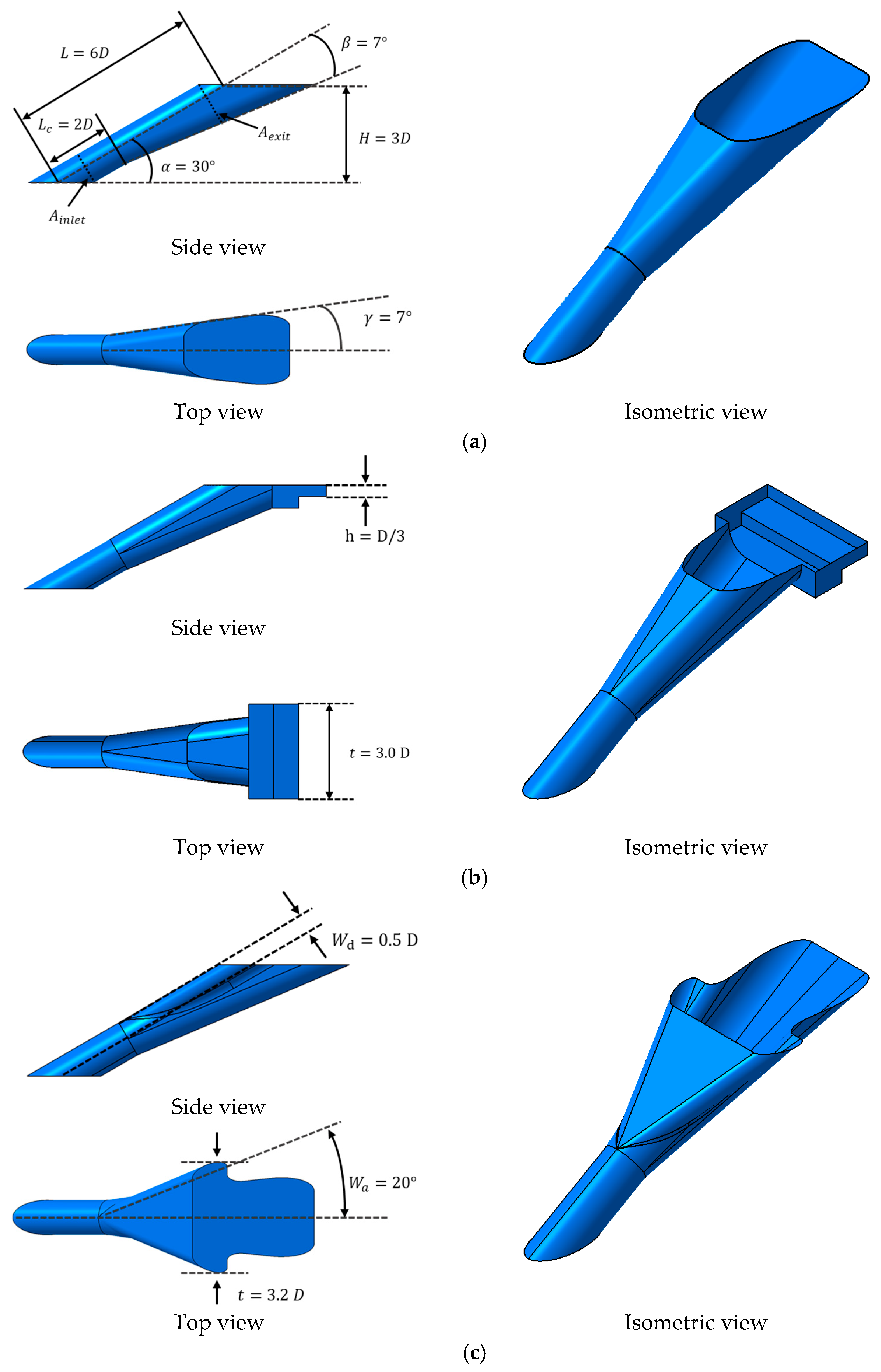
2.1. Geometry of the Film Cooling Hole
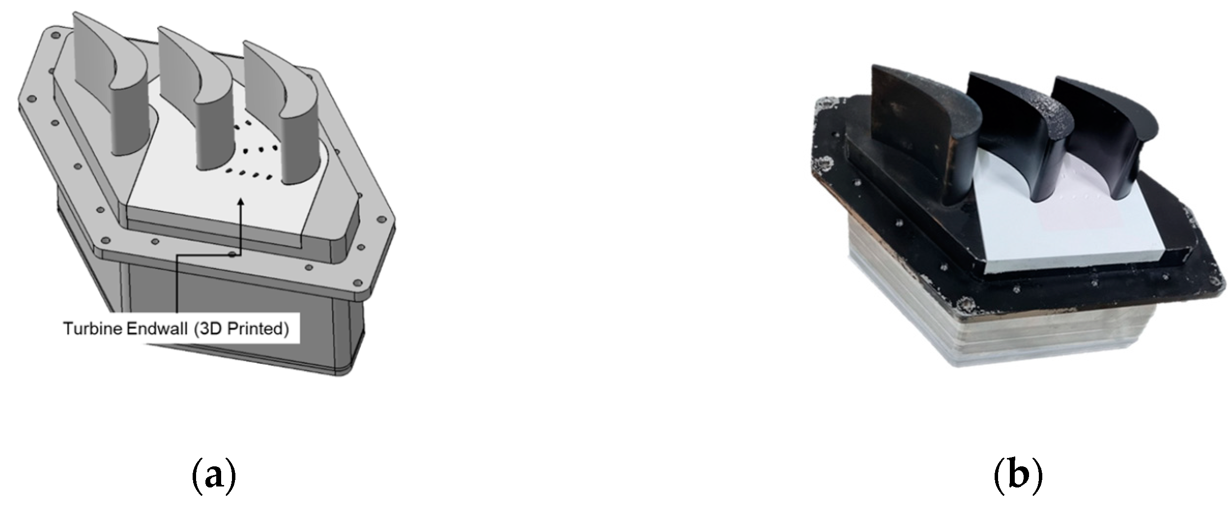
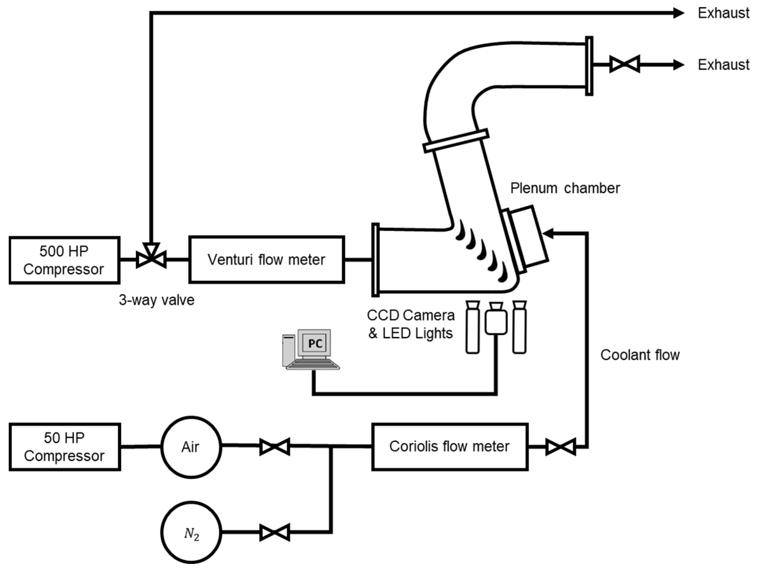
In the previous research by Kim et al. [22], experiments were conducted by installing three different film cooling hole configurations on a flat plate to measure the adiabatic film cooling effectiveness using PSP method. The 7-7-7 fan-shaped film cooling hole, commonly employed in film cooling techniques, is used as the Baseline. The notation “7-7-7” signifies that the flow direction at the exit of the hole is expanded by 7 ° in both the streamwise and lateral directions. Furthermore, two modified configurations were proposed based on the Baseline to enhance film cooling performance at a high blowing ratio. The first modified configuration, the Staircase, is characterized by a double-step structure expanded laterally by 3.0 D at the outlet of the Baseline. The height of the step within the double-step structure is one-third of the hole’s diameter. This geometry is designed to prevent the separation of the coolant from the surface while promoting a more uniform injection of the coolant under high blowing ratios. The second modified configuration, the Compound Expansion, features an additional expanded flow passage at the leading edge of the Baseline. The additional expanded flow passage is a configuration that expands laterally at 20 ° , with a size of 0.5 D. Coolant injected through the film cooling hole tends to accelerate at the hole’s upper region due to the separation bubble within the hole. This phenomenon can lead to surface detachment of the coolant and a decrease in cooling performance, especially under high blowing ratios. To address this, the Compound Expansion designed a laterally expanded additional flow passage at the leading edge of the Baseline to disperse the high momentum of the coolant, thus enhancing cooling performance. In the flat plate experiments [22], both modified configurations demonstrated better cooling performance compared with the Baseline under high blowing ratios. In this current study, these hole configurations were installed on the turbine endwall to investigate their characteristics in the complex flow environment within the turbine passage. The details of each configuration are presented in Figure 3, Table 1 and Table 2.

2.2. Test Facility

Figure 4 and Table 3 illustrate a schematic diagram of the endwall specimen used in this experiment, along with the locations of the holes. Nine holes were manufactured within the turbine endwall, each with a different injection direction depending on its location on the turbine endwall and mainstream direction. Figure 5 shows the plenum chamber and specimen used for the cascade experiments. The specimens were produced using a 3D printer with SLA (stereolithography) technology. The shape of the turbine in the cascade used in this study imitated the high-pressure turbine vanes of an aerospace turbofan engine [23]. The experiments were conducted in a linear cascade with a total of six passages. The equipment used in this experiment was identical to that used in previous research by Chung et al. [23], and an overview of the equipment is shown in Figure 6. The mainstream flow was supplied using a 500 hp compressor. The mass flow rate of the mainstream was measured using a Venturi flow meter located upstream of the experimental rig, and mass flow rate control was achieved by adjusting a 3-way valve at the compressor outlet. For the PSP technique, air and nitrogen gas were used as coolants. Air was supplied using a 50 hp compressor, while nitrogen gas was provided through four high-pressure cylinders. A Coriolis mass flow meter was installed in the coolant supply line to measure the mass flow rate of the supplied coolant, and the mass flow rate of the coolant was regulated through a valve downstream of the flow meter. To facilitate the PSP technique, two LEDs (LM2X-DM-400, ISSI) emitting light at a wavelength of approximately 400 nm and one CCD camera (PSP-CCD-M, ISSI) were installed to capture the emitted light intensity on the endwall.

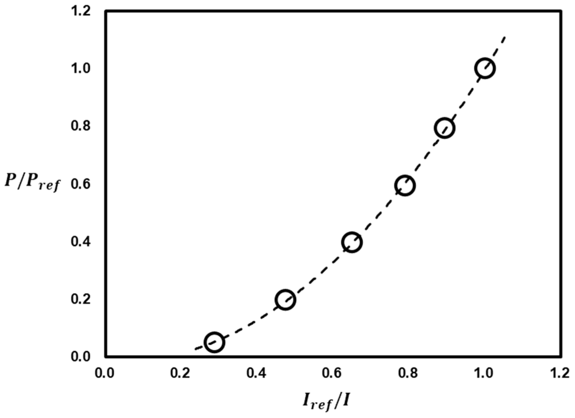
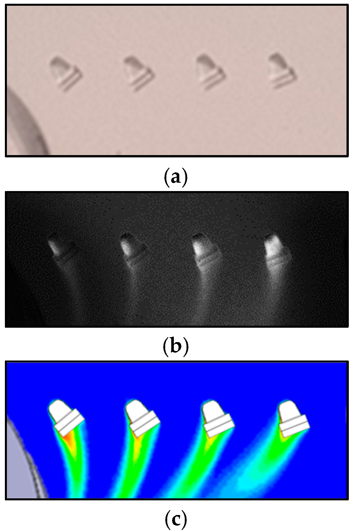
2.3. Experimental Method

The measurement of adiabatic film cooling effectiveness was conducted using Pressure Sensitive Paint (PSP), as previously employed in the study by Kim et al. [22]. Pressure-sensitive paint has been utilized in various studies for conducting film cooling measurement experiments [4,5,6,7,8,9,20,21,22,24,25,26,27]. PSP has the characteristic of changing luminescence intensity based on the surface oxygen partial pressure when exposed to specific frequencies of light. The experiment for measuring adiabatic film cooling effectiveness using PSP utilizes this property along with heat-mass transfer similarity. When using a different gas as the coolant instead of oxygen, the surface oxygen partial pressure decreases. The luminescence intensity of PSP varies according to the extent of the decrease in surface oxygen partial pressure. Areas with high intensity correspond to regions with a higher partial pressure of the foreign gas, indicating effective application of film cooling. The measurement of film cooling effectiveness using PSP is advantageous for experiments at specific density ratios, depending on the choice of the foreign gas. Additionally, it minimizes errors due to three-dimensional conduction effects, as there is almost no temperature difference between the mainstream flow and the coolant. However, the method requires the assurance of heat and mass transfer similarity, and it cannot measure heat transfer coefficients. The measurement of adiabatic film cooling effectiveness is described in the following paper [27], and the equation is as follows:
η = T a w T m a i n T c o o l a n t T m a i n = 1 1 P O 2 a i r P O 2 f g P O 2 a i r ω f g ω a i r + 1
In Equation (1), η represents the adiabatic film cooling effectiveness. P O 2 a i r and P O 2 f g are the partial pressure of oxygen when air or foreign gas is injected. ω f g is the molecular weight of the foreign gas, and ω a i r is the molecular weight of the air. The ratio of the molecular weight is ω f g ω a i r , which represents the density ratio of the coolant to mainstream.
To calculate the adiabatic film cooling effectiveness using the above equation, a correlation between the oxygen partial pressure on the PSP-coated surface and the luminescence of PSP is required. In this study, a vacuum chamber was constructed, similar to the previous research by Kim et al. [22], to measure the luminescence intensity of PSP as a function of the oxygen partial pressure on the surface, as shown in Figure 7. A 400 nm wavelength LED illumination was employed to excite the PSP, and the luminescence intensity resulting from the PSP reaction was captured using the CCD camera (PSP-CCD-M, ISSI) and a bandpass filter. Binary FIB PSP from ISSI was used in this study, and it was determined that the change in luminescence intensity due to temperature change within the temperature range (10~40 °C) was negligible. Figure 8 shows the specimen coated with PSP, images captured during the experimental process showing the luminescence of the applied PSP, and the results after data processing. When using a foreign gas as the coolant on the specimen coated with PSP, as in Figure 8b, luminescence occurs in areas with a high concentration of the foreign gas. The data obtained during the experiment, like Figure 8b, can be used with Equation 1 and the calibration curve in Figure 7 to calculate the adiabatic film cooling effectiveness, resulting in the outcomes presented in Figure 8c. Uncertainty in this study was calculated based on the research by Natsui et al. [28]. At η = 0.5, the uncertainty was approximately ±5.2%, and at η = 0.2, it was approximately ±16.1%.

2.4. Test Conditions

The test conditions for this study are presented in Table 4. The Reynolds numbers of the mainstream are approximately 4.0 × 10⁵ based on the turbine inlet velocity and 5.7 × 10⁵ based on the turbine exit velocity. Nitrogen was used as the foreign gas for the PSP technique in this experiment, resulting in a density ratio of 1.0 between the mainstream and the coolant. The MFR varied from 0.25% to 1.25% of the mass flow rate passing through the single turbine passage, with increments of 0.25%, resulting in five different conditions.
Due to the acceleration of the mainstream within the turbine passage, the surface pressures at the exits of holes manufactured on the endwall differ. So, the blowing ratio varies with the hole location on the endwall. Measuring the mass flow rate injected through each hole individually is difficult. Therefore, the average blowing ratios for each row of the holes are calculated through computational analysis and presented in Table 4. To measure the velocity profile of the mainstream, a test module was constructed as shown in Figure 9a, and the velocity profile of the mainstream measured at a distance of 0.2 C from the leading edge of the turbine vane is shown in Figure 9b. With respect to the Reynolds number based on inlet velocity, it can be assumed that fully turbulent flow is achieved, and the boundary layer thickness is approximately 0.3 times the span length of the turbine blade.

3. Results and Discussion

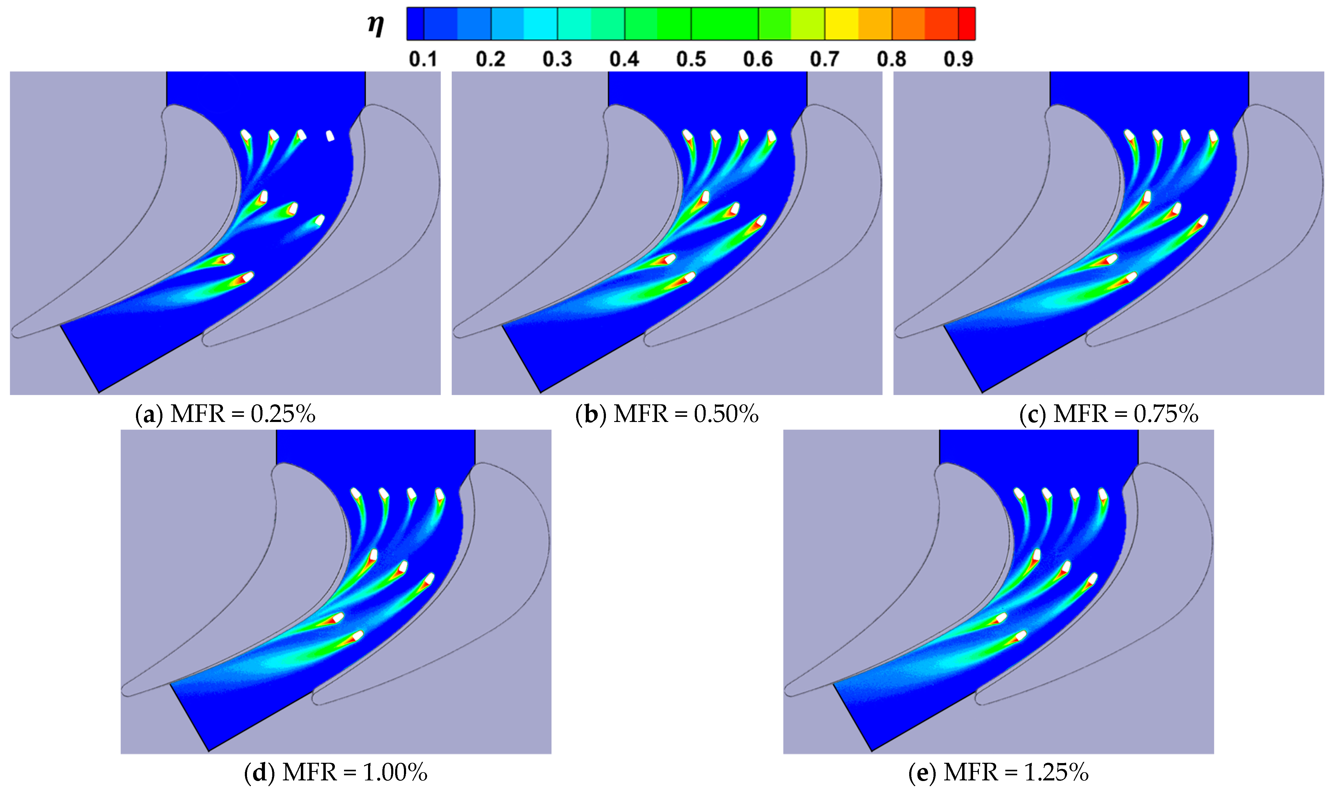
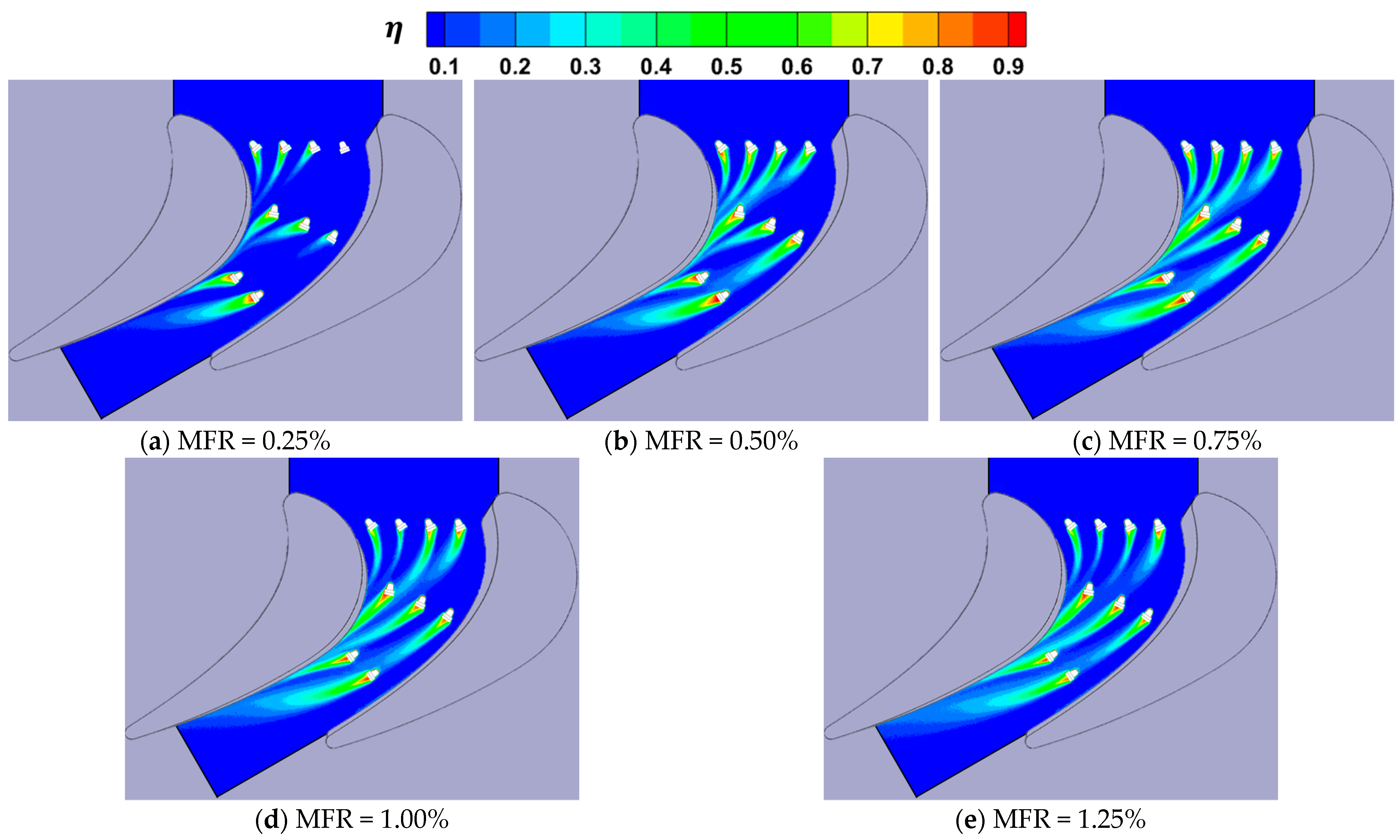
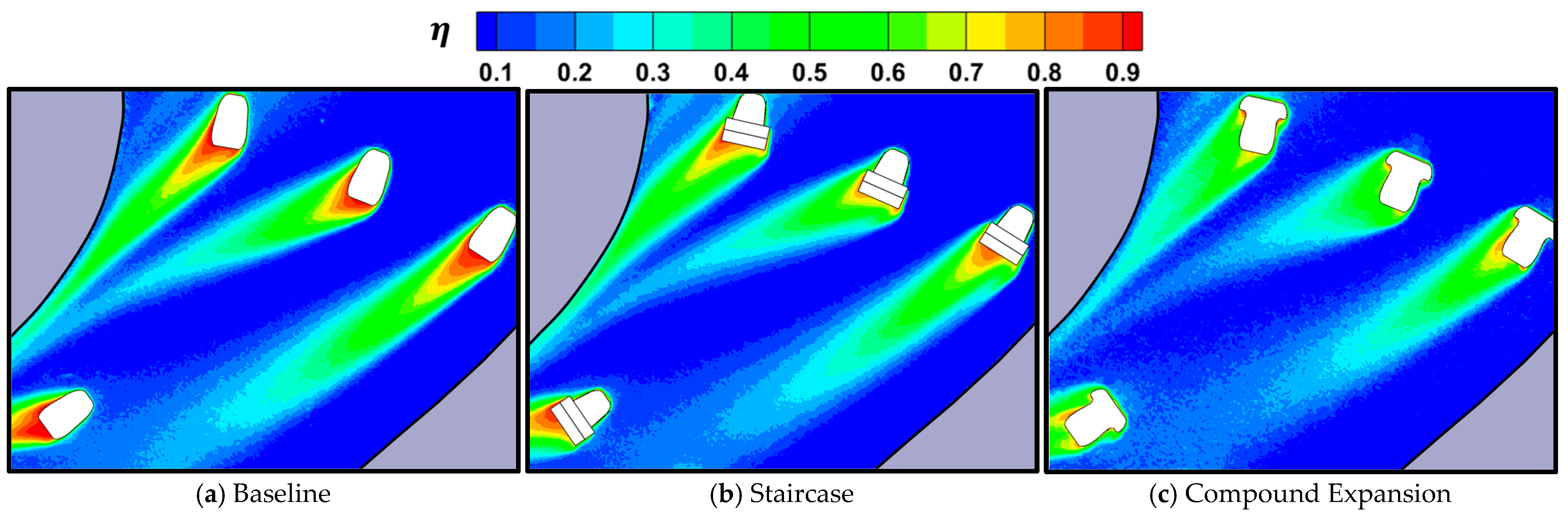
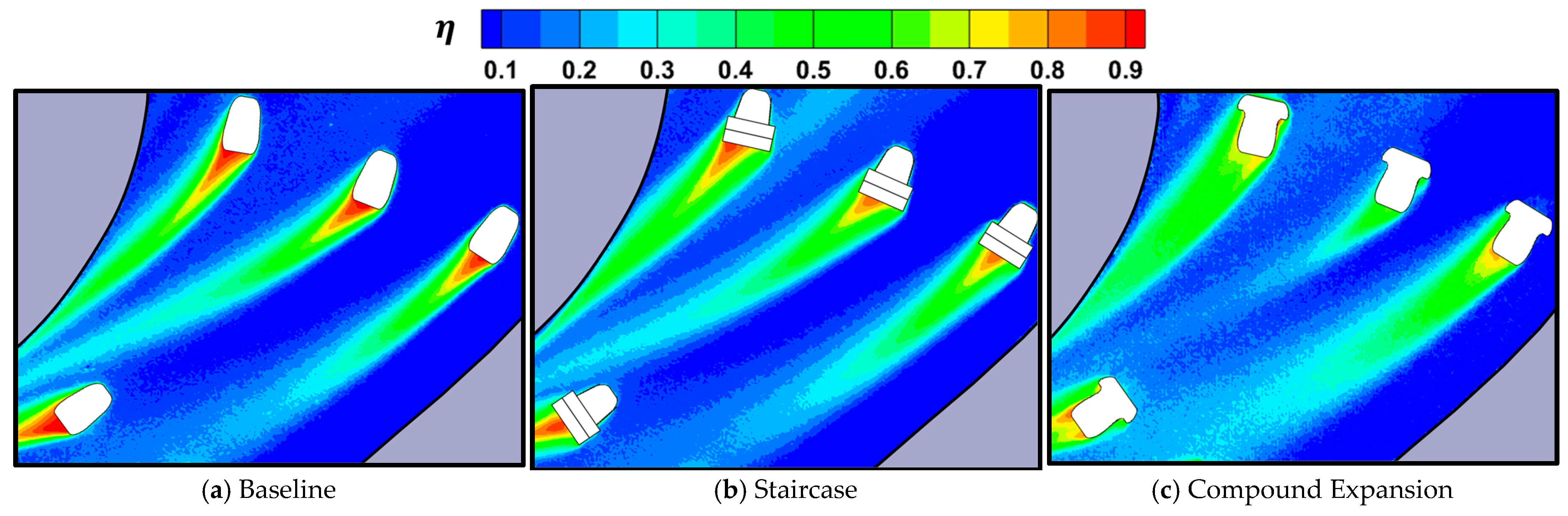
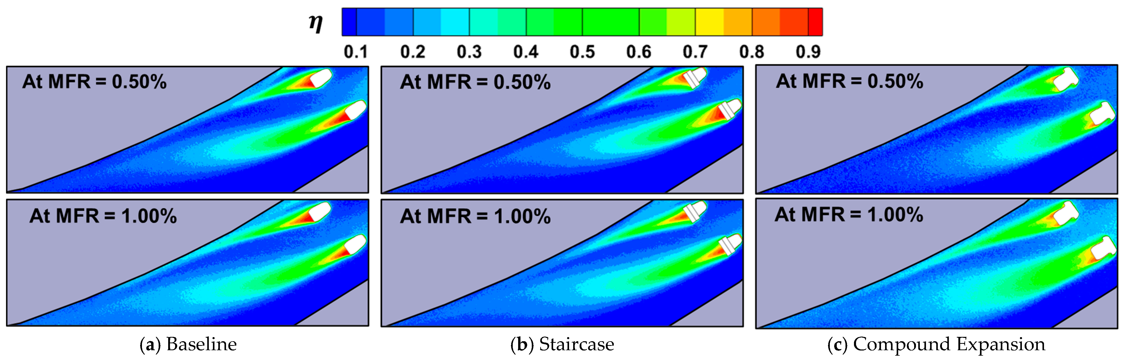
3.1. Distribution of Film Cooling Effectiveness

Figure 10, Figure 11 and Figure 12 show the distribution of adiabatic film cooling effectiveness for each hole configuration at various MFR conditions. Within the turbine passage, the acceleration of the mainstream, pressure gradients between the pressure and suction surfaces, and secondary flows occur regardless of the MFR, affecting all test conditions. In the turbine passage, the pressure is highest near the upstream region and decreases downstream as the mainstream flow accelerates. So, as previously mentioned, when supplying coolant to each hole’s location from a single chamber, the pressure at the exit of each hole varies, resulting in different film cooling mass flow rates for each hole’s location. As a result, the holes in the first row, positioned upstream, exhibit lower flow velocity and higher pressure compared with those in the other rows. Therefore, a relatively lower quantity of coolant is injected through these holes. Especially hole numbers 1-4 is hard, due to its due to its proximity to the pressure side, making it particularly difficult for coolant to be effectively injected. Conversely, downstream in the region where the mainstream is accelerated, the third row demonstrates higher film cooling effectiveness compared with the other rows.
Also, the turbine passage consists of the pressure and suction sides, leading to a pressure gradient from the pressure side to the suction side within the passage. This pressure gradient causes injected coolant to be swept from the pressure side toward the suction side, and this phenomenon is observed through the film cooling effectiveness distribution.
Furthermore, as the mainstream enters the turbine, it develops a horseshoe vortex at the leading edge of the turbine. This vortex, when introduced into the passage, evolves into a passage vortex that crosses from the pressure side to the suction side of the passage. The contour plots of film cooling effectiveness show that holes 1-4, 2-2, and 3-1 are directly influenced by the passage vortex, leading to a sharp turn toward the suction side compared with other holes in the same row. This phenomenon is particularly pronounced at low MFR, gradually diminishing as MFR increases.
For MFR = 0.25%, as previously explained, the pressure difference between the upstream and downstream regions results in low cooling effectiveness in the first row and higher cooling performance in the downstream. In particular, none of the hole configurations show significant film cooling effectiveness near holes 1-4 due to their nearness to the pressure side, making it difficult for coolant to be effectively injected. The Compound Expansion configuration, in contrast to other configurations, does not show a film cooling effectiveness trajectory at 1-3 and 2-3 holes. In previous research [22], under low blowing ratio conditions, Compound Expansion performed poorly compared with other configurations due to the reduction in coolant momentum caused by the additional expanded flow passage. This led to an increased inflow of mainstream and a decrease in cooling performance. In endwall conditions, the complex secondary flow causes low-momentum coolant to be mixed in the mainstream flow, reducing cooling performance.
For MFR = 0.50%, with an increase in coolant supply, film cooling effectiveness trajectories are observed for all hole configurations. Compared with the results of MFR = 0.25% and 0.50%, when supplying coolant to the turbine endwall through a single chamber, it is observed that under certain MFR conditions, coolant is biasedly injected through some holes. However, when a certain MFR is supplied, all film cooling holes show the injection of coolant. Additionally, an increase in MFR leads to an increase in film cooling effectiveness and a stretch of the effectiveness trajectory. The result suggests that the characteristics observed in film cooling experiments on flat plates, where an increase in blowing ratio leads to an increase in film cooling effectiveness and a stretch of the trajectory, are similar in the turbine endwall.
For MFR = 0.75%, the increased supply of coolant leads to a higher momentum of the coolant being injected, resulting in less leaning towards the suction side due to the influence of pressure gradients compared with lower MFR conditions. In the case of the Baseline, the width of cooling effectiveness trajectories in the first row is reduced. This phenomenon can be described as the lift-off, due to increasing the momentum of the coolant. On the other hand, for the improved configurations, modified configurations have been made to reduce the effects of lift-off on cooling performance. Consequently, it is observed that under MFR = 0.75% conditions, the Baseline shows an earlier degradation in cooling performance compared with other configurations.
For MFR = 1.00% and 1.25%, it is noted that cooling effectiveness trajectories from the first row become thinner for all configurations. When considering this trend, it becomes evident that the modified configurations exhibit lift-off phenomena under high MFR conditions compared with the Baseline. Specifically, the 2-2 hole in the Compound Expansion configuration shows thinner cooling effectiveness trajectories compared with other configurations. Compound Expansion utilizes an additional expanded flow passage with a wide lateral angle to reduce the high momentum of the coolant. Consequently, coolant injected in this type, particularly from the side facing the suction surface, aligns with the swirl direction of the passage Vortex, causing it to be mixed into the mainstream. This characteristic of Compound Expansion results in thinner cooling effectiveness trajectories at the 2-2 hole. Furthermore, the 2-1 hole near the suction surface exhibits better cooling performance compared with other holes within the same row, particularly under high MFR conditions. Despite the presence of a low-pressure region near the suction surface, it does not show a significant degradation in cooling performance. This phenomenon can be attributed to the accelerated mainstream flow near the suction surface, which effectively presses the injected coolant against the wall, thereby preventing lift-off.

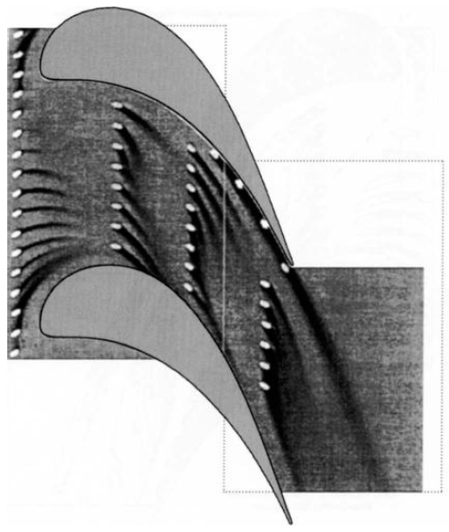
3.2. Effect of Secondary Flow within the Turbine Passage

Figure 13 shows the film cooling effectiveness trajectory at the second row of holes (MFR = 0.50%). For all hole configurations, the passage vortex directly influences the film cooling effectiveness trajectory at the 2-2 hole. Baseline, in particular, shows a higher film cooling effectiveness and longer trajectory compared with other configurations. The reason is that the Staircase and Compound Expansion were designed to reduce the negative effects of lift-off under high blowing ratio conditions. However, under low MFR conditions, they exhibit less performance compared with the Baseline. The double-step structure of the Staircase is designed to reduce the momentum of the injected coolant and achieve uniform injection. Additionally, in the previous study on the flat plate, the laterally expanded double-step configuration showed improved performance by offering protection over a wider area in the lateral direction. However, when installed on the endwall, the reduction in momentum within the double-step can lead to the inflow of mainstream into the double-step, resulting in a reduction in cooling performance. Furthermore, it is more susceptible to the influence of secondary flows like the passage vortex, which means that significant improvements compared with the Baseline are not observed, especially at low MFR conditions.
Compound Expansion exhibits shorter cooling effectiveness trajectories compared with other configurations. In previous research on the flat plate, Compound Expansion demonstrated improved performance under high blowing ratio conditions by utilizing additional expanded passage to protect a broader area in the lateral direction and reduce the momentum of the coolant. However, the reduced momentum in the coolant makes it more susceptible to the influence of secondary flows, particularly in the case of the 2-2 hole, where direct effects from the Passage Vortex are significant, resulting in shorter film cooling effectiveness trajectories and lower cooling effectiveness compared with other configurations. In Figure 14, the cooling effectiveness trajectory in the second row of holes at MFR = 1.00% is depicted. Similar to Figure 12, the trajectory sweeps from the pressure side to the suction side direction at the 2-2 hole. However, the degree of sweeping is less compared with the results at MFR = 0.50%. Observing this, it can be confirmed that with the increasing MFR, the impact of secondary flows is reduced, as previously mentioned. As a result, modified hole configurations show enhanced cooling performance, as observed in previous tests on the flat plate.

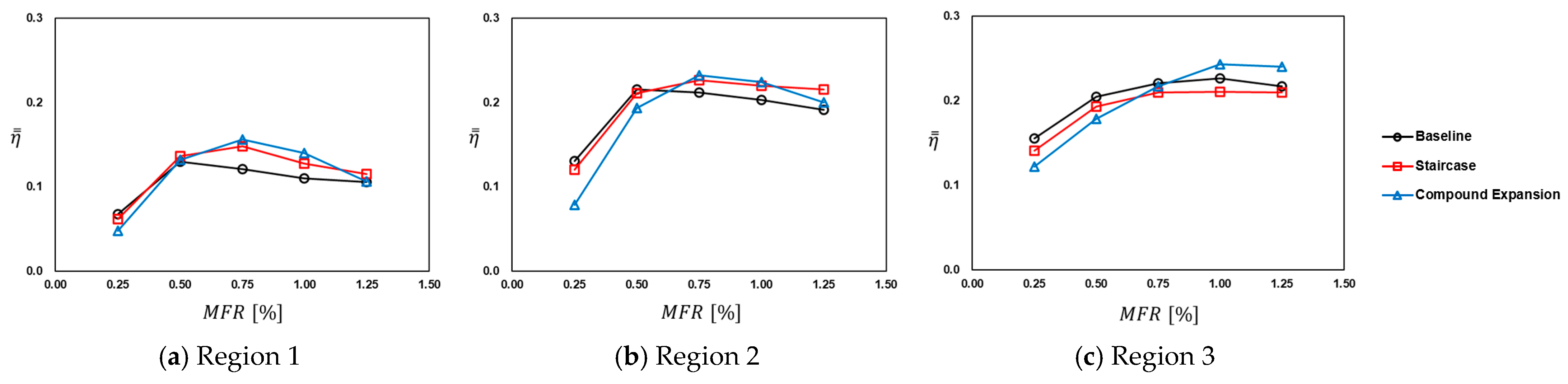
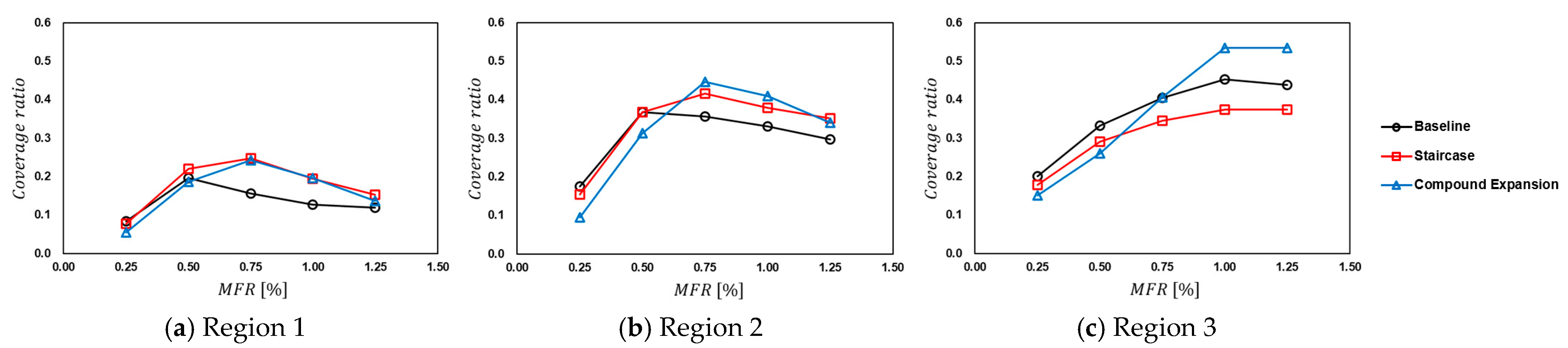
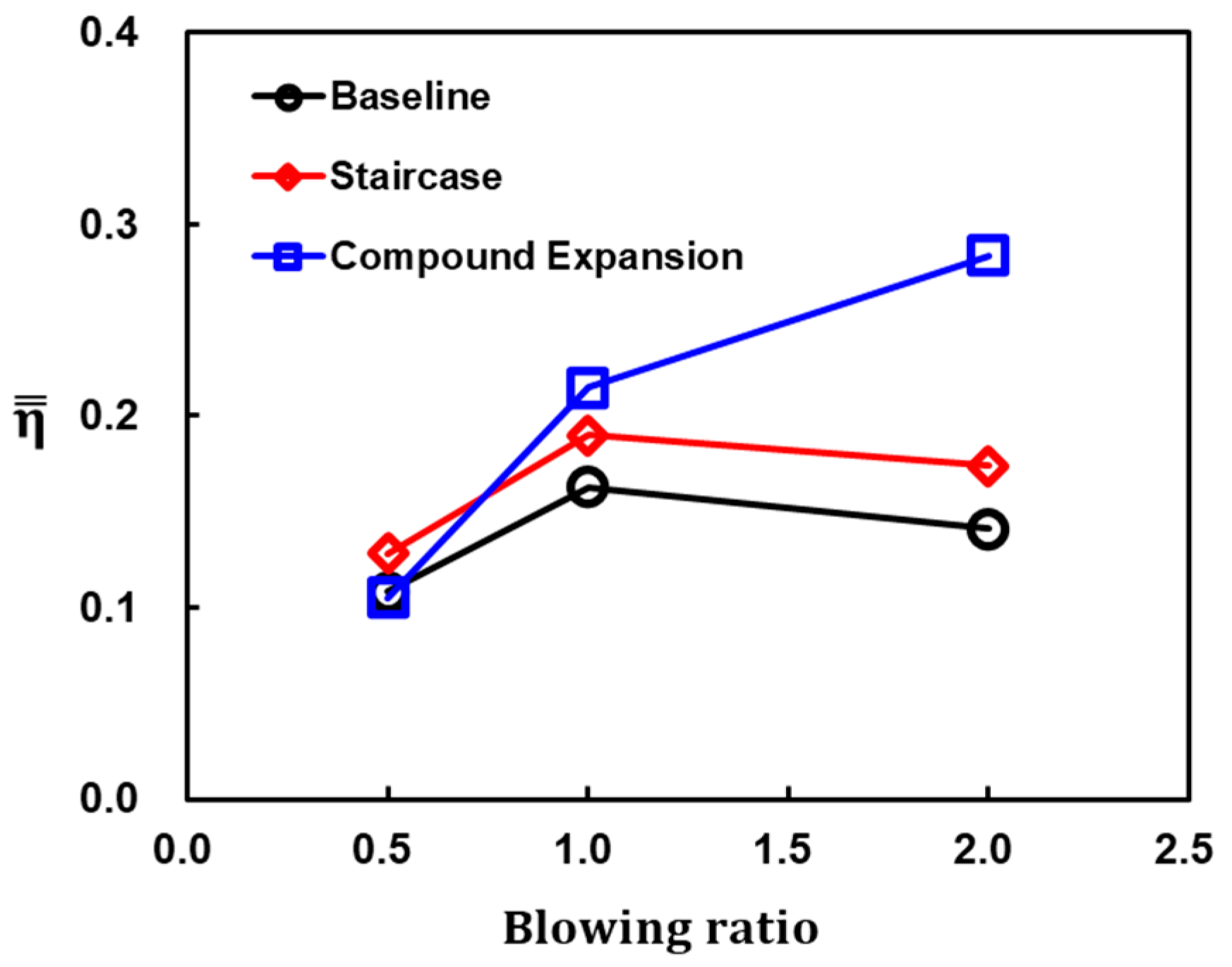
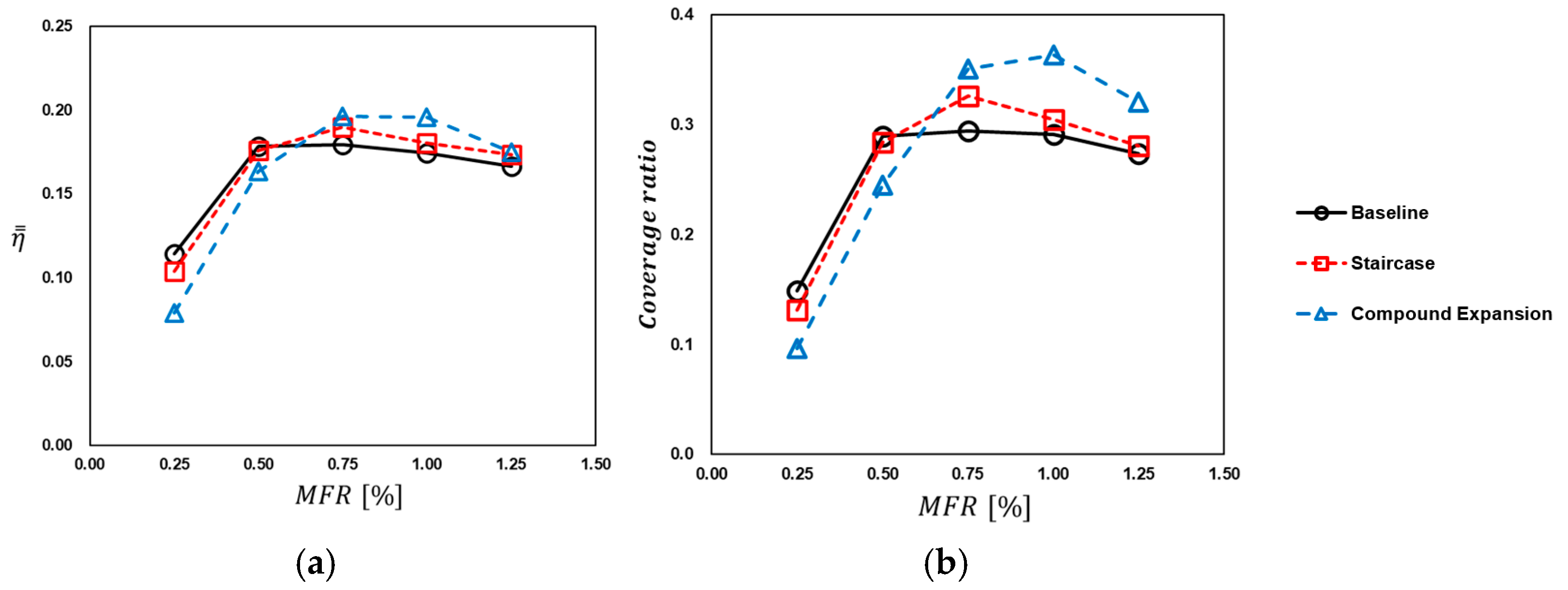
3.3. Averaged Film Cooling Effectiveness

Figure 15 shows the three regions of the endwall divided based on the rows of film cooling holes. Figure 16 shows the area-averaged film cooling effectiveness for each region and the Coverage ratio in each region depicted in Figure 17. The Coverage ratio refers to the portion of the overall area where film cooling effectiveness is above 0.2. This is because Region 1 has a relatively larger area exposed by the mainstream, while Regions 2 and 3 benefit from the acceleration of the mainstream and narrower passages, resulting in better performance. In Region 3, as the MFR increases, both effectiveness and Coverage ratio initially improve but then stabilize. Region 3 is located downstream in the turbine passage, where the mainstream accelerates. The accelerated mainstream creates a thin boundary layer, which presses the injected coolant against the wall. In the high blowing ratio condition, the film cooling effectiveness is decreased by the lift-off effect. However, the area-averaged film cooling effectiveness and Coverage ratio in Region 3 show better cooling performance than the other regions due to the acceleration of the mainstream and the thin boundary layer.
For the Baseline, a decrease in effectiveness and Coverage ratio is observed in Regions 1 and 2, starting after MFR = 0.50%. This decreasing trend, as seen earlier in the film cooling effectiveness distribution, is attributed to the lift-off phenomenon of the coolant. The modified configurations are designed to reduce the decrease in cooling performance caused by lift-off, and they demonstrate better resistance to lift-off, especially at higher MFR conditions. The Staircase configuration exhibits a similar trend to the Baseline in Regions 1 and 2, but it shows an overall improvement in cooling performance, as also observed in previous flat plate tests. However, in Region 3, a decrease in performance compared with the Baseline can be observed. Region 3 represents an area where the mainstream accelerates, leading to longer cooling trajectories compared with other regions. The Staircase design features a double-step structure, which causes the coolant to collide with the steps upon ejection. This collision reduces the momentum of the coolant, and simultaneously, the expansion of the step structure upon ejection results in the coolant spreading out more extensively in the lateral direction. As a result, in all conditions of low MFR and high MFR, the cooling trajectory of the Staircase in Region 3, as shown in Figure 18a,b, appears slightly shorter compared with the cooling trajectory of the Baseline, leading to a slight reduction in cooling performance. The Compound Expansion design reduces the momentum of the coolant due to the additional expanded flow passage. This reduced momentum causes lower cooling performance and Coverage ratios at low MFR conditions compared with other configurations. However, at high MFR conditions, it shows similar or even better performance than other configurations. Particularly in regions with minimal secondary flow influence, such as Region 3, as seen in Figure 18c, the improvement in cooling performance is more pronounced.
Figure 19 shows the results of the previous flat plate experiment [22], showing the area-averaged film cooling effectiveness for x/D = 3~30 at different blowing ratios. In Figure 20, the averaged film cooling effectiveness and Coverage ratio across the entire endwall area are presented. It can be observed that there is a slight difference between the results obtained from the flat plate and those from the turbine endwall. These results show the influence of the complex mainstream flow within the turbine passage on film cooling. These results show that when applying film cooling holes to the actual turbines, it is essential to have experimental results from both flat plate studies and experiments conducted within the turbine. The Baseline configuration initially exhibits better or similar results to other configurations at low MFR but initiates a decrease in cooling performance at MFR = 0.75% compared with the other configurations. The Staircase shows a similar trend to the Baseline but demonstrates improved cooling performance overall, even surpassing the Baseline at higher MFR conditions. This trend is similar to the observed trend in the previous experiments on the flat plate, as shown in Figure 19. Compound Expansion shows cooling performance that is approximately 31% lower than the Baseline at MFR = 0.25%. However, as MFR increases, a significant improvement in cooling performance becomes evident, with a maximum enhancement of up to 12%. At high MFR conditions, it shows an increase in area-averaged cooling effectiveness of up to 5.9%. At MFR = 1.25%, the Staircase and the Compound Expansion show nearly identical film cooling effectiveness, while their Coverage ratio values differ. This indicates that the Staircase has good cooling performance in specific regions, while Compound Expansion provides wider coverage. In these results, while the area-averaged film cooling effectiveness serves as one factor in cooling performance, there are cases where cooling effectiveness is high only in localized regions. Therefore, when applying film cooling holes to an actual turbine, it is essential to consider factors such as the Coverage Ratio, which represents the extent of the protected area, in addition to the area-averaged effectiveness.
In summary, compared with the flat plate test, the expansion at the hole exit leads to an improvement in cooling performance when a high mass flow rate of coolant is supplied in an environment without secondary flows. However, under conditions with secondary flows, the impact of secondary flows becomes more significant due to the dispersion of coolant momentum, resulting in a reduction in cooling performance. When considering the results along with those obtained from the flat plate tests, it can be concluded that the Staircase exhibits a similar trend to the Baseline but achieves better cooling performance. The Compound Expansion may underperform at low MFR but shows good cooling performance at high MFR. Moreover, Compound Expansion offers a wider protection region on the endwall compared with other configurations, despite similar cooling effectiveness.

4. Conclusions

In this study, the adiabatic film cooling effectiveness on the endwall was measured for various film cooling hole configurations, including the baseline and two modified configurations based on the results from previous flat plate tests. The measurement was conducted using pressure-sensitive paint under different coolant-to-mainstream mass flow ratio (MFR) conditions to evaluate and compare film cooling performance. The two modified hole configurations were summarized as follows: The Staircase featured a double-step structure at the exit of the Baseline to reduce the lift-off effect at high blowing ratios and ensure more uniform coolant distribution. Compound Expansion created an additional expanded flow passage at the leading edge of the baseline configuration to disperse the coolant and enhance film cooling effectiveness at high blowing ratios. Previous research showed that both configurations outperformed the baseline in terms of film cooling effectiveness. Within the turbine passage, complex mainstream flow exists. Therefore, in this study, the film cooling holes used in previous experiments were installed in the turbine endwall to investigate the film cooling characteristics within the turbine passage. The summary of the results is as follows:
  • Film cooling in all configurations is influenced by secondary flows and mainstream flow acceleration within the turbine passage.
  • When the AR is large, the film cooling is more significantly influenced by the secondary flow within the passage.
  • The Baseline shows better film cooling performance at low MFR conditions.
  • The Staircase, featuring a double-step structure, behaves similarly to the Baseline but shows reduced performance degradation due to lift-off at high blowing ratios. Moreover, the lateral expansion of the double-step structure enhances the overall protection area.
  • The Compound Expansion shows lower film cooling performance at low MFR conditions, but at high MFR, the Compound Expansion shows enhanced cooling performance due to the reduction in the momentum of the coolant by the additional expanded flow passage. In addition, the additional flow passage in the Compound Expansion provides broader surface coverage compared with other configurations, contributing to its enhanced film cooling performance.
  • The modified configurations to reduce the momentum of the coolant show less cooling performance than the Baseline at low MFR conditions. However, as MFR increases, the modified configurations align with their design intent, resulting in enhanced film cooling performance compared with the Baseline.
Consequently, the results show that the influence of secondary flows and mainstream flow acceleration on film cooling is significant in all configurations within the turbine passage. The performance of the modified configurations, the Staircase and the Compound Expansion, aligns more closely with their design intent as MFR increases, resulting in enhanced film cooling performance on the endwall compared with the Baseline. A comparison of the cooling performance over the entire surface area is similar to experiments conducted on flat surfaces. However, there are differences in the localized cooling effectiveness distribution. In these observations, testing within the turbine passage is essential to compare the cooling performance under the influence of complex flow patterns within the turbine passage after conducting tests on flat surfaces. Previous and current research has compared the film cooling performance between a flat plate and the turbine endwall. These results will be directly helpful in selecting film cooling holes for use in gas turbines.

Author Contributions

Conceptualization, S.K. and D.-H.R.; methodology, S.K., D.L. and D.-H.R.; software, S.K. and Y.S.K.; validation, S.K., D.L., Y.S.K. and D.-H.R.; formal analysis, S.K. and D.-H.R.; investigation, S.K. and D.-H.R.; resources, S.K. and D.-H.R.; data curation, S.K.; writing—original draft preparation, S.K.; writing—review and editing, Y.S.K. and D.-H.R.; visualization, S.K.; supervision, Y.S.K. and D.-H.R.; project administration, D.-H.R.; funding acquisition, D.-H.R. All authors have read and agreed to the published version of the manuscript.

Funding

This research was funded by the Defense Rapid Acquisition Technology Research Institute (Grant number: UC190008D).

Data Availability Statement

Data is contained within this article.

Conflicts of Interest

The authors declare no conflict of interest.

Nomenclature

Ahole cross-sectional area
ARarea ratio of outlet to inlet
Cchord length of turbine blade
Dhole diameter
DRdensity ratio of coolant to mainstream
FWDnormalized location in the forward direction
Hheight of turbine blade
hstep height
h′distance from the endwall in the blade span direction
Ilight intensity
Lhole length
LATnormalized location in the lateral direction
L c length of the cylindrical hole section
MFRmass flow ratio of coolant to mainstream
Ppressure
RANSReynolds-Averaged Navier-Stokes equation
Ttemperature
thole breakout width
ulocal streamwise velocity
W a lateral expansion angle of the additional flow passage
W d diameter of the additional flow passage
Greek symbol
αinjection angle
βforward expansion angle
γlateral expansion angle
ρ fluid density
ηadiabatic film cooling effectiveness
ωmolecular weight
subscripts
coolantcoolant flow
mainmainstream
awadiabatic wall
inletinlet plane of the film cooling hole
exitexit plane of the film cooling hole
refreference
superscripts
̿ area-averaged

References

  1. Bogard, D.G.; Thole, K.A. Gas Turbine Film Cooling. J. Propuls. Power 2006, 22, 249–270. [Google Scholar] [CrossRef]
  2. Goldstein, R.J. Film Cooling. In Advances in Heat Transfer; Elsevier: Amsterdam, The Netherlands, 1971; Volume 7, pp. 321–379. [Google Scholar]
  3. Goldstein, R.J.; Eckert, E.R.G.; Burggraf, F. Effects of Hole Geometry and Density on 3-Dimensional Film Cooling. Int. J. Heat Mass Transf. 1974, 17, 595–607. [Google Scholar] [CrossRef]
  4. Rallabandi, A.P.; Grizzle, J.; Han, J.-C. Effect of Upstream Step on Flat Plate Film-Cooling Effectiveness Using PSP. J. Turbomach. 2011, 133, 041024. [Google Scholar] [CrossRef]
  5. Wright, L.M.; Mcclain, S.T.; Clemenson, M.D. Effect of Density Ratio on Flat Plate Film Cooling with Shaped Holes Using PSP. J. Turbomach. 2011, 133, 041011. [Google Scholar] [CrossRef]
  6. Narzary, D.P.; Liu, K.C.; Rallabandi, A.P.; Han, J.-C. Influence of Coolant Density on Turbine Blade Film-Cooling Using Pressure Sensitive Paint Technique. J. Turbomach. 2012, 134, 031006. [Google Scholar] [CrossRef]
  7. Wang, H.; Wright, L.M. Effect of Inlet Geometry on Flat Plate, Film Cooling Effectiveness from Shaped Holes. In Proceedings of the ASME 2021, Online, 1–5 November 2021. IMECE2021-73135. [Google Scholar]
  8. Song, Y.J.; Park, S.H.; Kang, Y.J.; Kwak, J.S. Effects of trench configuration on the film cooling effectiveness of a fan-shaped hole. Int. J. Heat Mass Transf. 2021, 178, 121655. [Google Scholar] [CrossRef]
  9. Park, S.H.; Kang, Y.J.; Seo, H.J.; Kwak, J.S.; Kang, Y.S. Experimental optimization of a fan-shaped film cooling hole with 30 degrees-injection angle and 6-hole length-to-diameter ratio. Int. J. Heat Mass Transf. 2019, 144, 118652. [Google Scholar] [CrossRef]
  10. Lu, Y.; Dhungel, A.; Ekkad, S.V.; Bunker, R.S. Effect of Trench width and depth on film cooling from cylindrical holes embedded in trenches. ASME J. Turbomach. 2009, 131, 011003. [Google Scholar] [CrossRef]
  11. Abdeh, H.; Barigozzi, G.; Zamiri, A.; Chung, J.T. PSP and LES Investigation on the Impact of Trench Depth on Flat Plate Film Cooling Through Shaped Holes. In Proceedings of the ASME Turbo Expo, Boston, MA, USA, 26–30 June 2023. GT2023-102890. [Google Scholar]
  12. Kim, G.M.; Kim, Y.J.; Kwak, J.S. Improvement of Film Cooling Performance of a Slot on a Flat Plate Using Coanda Effect. KSFM J. Fluid Mach. 2017, 20, 5–10. [Google Scholar] [CrossRef]
  13. Okita, Y.; Ideta, T.; Fujimoto, S. Multi-Objective Shape Optimization of Arrowhead-shaped Film Cooling Hole on Transonic Turbine Blade. In Proceedings of the ASME Turbo Expo, Online, 23–25 September 2020. GT2020-14721. [Google Scholar]
  14. Gritsch, M.; Colban, W.; Schar, H.; Dobbeling, K. Effect of Hole Geometry on the Thermal Performance of Fan-Shaped Film Cooling Holes. J. Turbomach. 2005, 127, 718–725. [Google Scholar] [CrossRef]
  15. Langston, L.S. Secondary Flows in Axial Turbines—A Review. Ann. N. Y. Acad. Sci. 2001, 934, 11–26. [Google Scholar] [CrossRef] [PubMed]
  16. Friedrichs, S.; Hodson, H.P.; Dawes, W.N. Distribution of Film-Cooling Effectiveness on a Turbine Endwall Measured Using the Ammonia and Diazo Technique. J. Turbomach. 1996, 118, 613–621. [Google Scholar] [CrossRef]
  17. Friedrichs, S.; Hodson, H.P.; Dawes, W.N. Aerodynamic Aspects of Endwall Film-Cooling. J. Turbomach. 1997, 119, 786–793. [Google Scholar] [CrossRef]
  18. Langston, L.S.; Nice, M.L.; Hooper, R.M. Three-Dimensional Flow Within a Turbine Cascade Passage. J. Eng. Power 1977, 99, 21–28. [Google Scholar] [CrossRef]
  19. Langston, L.S. Crossflows in a Turbine Cascade Passage. J. Eng. Power. 1980, 102, 866–874. [Google Scholar] [CrossRef]
  20. Charbonnier, D.; Ott, P.; Jonsson, M.; Cottier, F.; Kobke, T. Experimental and Numerical Study of the Thermal Performance of a Film Cooled Turbine Platform. In Proceedings of the ASME Turbo Expo, Orlando, FL, USA, 8–12 June 2009. GT2009-60306. [Google Scholar]
  21. Shiau, C.-C.; Sahin, I.; Ullah, I.; Han, J.-C.; Mirzamoghadam, A.V.; Riahi, A.; Stimpson, C. Transonic Turbine Vane Endwall Film Cooling Using PSP Measurement Technique. In Proceedings of the ASME Turbo Expo, Pheonix, AZ, USA, 17–21 June 2019. GT2019-91030. [Google Scholar]
  22. Kim, S.; Lee, D.; Kang, Y.S.; Rhee, D.-H. Experimental Study on the Improvement of Film Cooling Effectiveness of Various Modified Configurations based on a Fan-Shaped Film Cooling Hole on a Flat Plate. Energies 2023, accepted. [Google Scholar]
  23. Chung, H.; Kim, S.; Rhee, D.-H.; Kang, Y.S. Measurement of Film Cooling Efficiency of Fan-shaped Holes on Endwall of Turbine Blades. KSFM J. Fluid Mach. 2021, 24, 5–15. [Google Scholar]
  24. Burdett, T.A.; Ullah, I.; Wright, L.M.; Han, J.-C.; McClintic, J.W.; Crites, D.C.; Riahi, A. Optimized Film Cooling Flow on a Contoured Endwall within a Transonic Annular Cascade. ASME J. Thermal Sci. Eng. Appl. 2023, 15, 041011. [Google Scholar] [CrossRef]
  25. Burdett, T.A.; Ullah, I.; Wright, L.M.; Han, J.-C.; McClintic, J.W.; Crites, D.C.; Riahi, A. Upstream and Passage Endwall Film Cooling of a Transonic Turbine Vane. J. Thermophys. Heat Transf. 2023, 37, 394–403. [Google Scholar] [CrossRef]
  26. Zhang, L.J.; Jaiswal, R.S. Turbine Nozzle Endwall Film Cooling Study Using Pressure-Sensitive Paint. ASME J. Turbomach. 2001, 123, 730–735. [Google Scholar] [CrossRef]
  27. Han, J.C.; Rallabandi, A.P. Turbine Blade Film Cooling using PSP Technique. Front. Heat Mass Transf. 2010, 1, 013001. [Google Scholar] [CrossRef]
  28. Natsui, G.; Little, Z.; Kapat, J.S.; Dees, J.E.; Laskowski, G. A Detailed Uncertainty Analysis of Adiabatic Film Cooling Effectiveness Measurements Using Pressure-Sensitive Paint. ASME J. Turbomach. 2016, 138, 081007. [Google Scholar] [CrossRef]
Figure 1. Flow visualization of passage vortex and induced vortices [15].
Energies 16 07733 g001
Figure 2. Visualization of coolant trajectories on the endwall [16].
Energies 16 07733 g002
Figure 3. Configurations of test film cooling hole [22]. (a) 7-7-7 Fan-shaped film cooling hole (Baseline); (b) Baseline with staircase geometry (Staircase); (c) Baseline with additional expanded flow passage (Compound Expansion).
Energies 16 07733 g003
Figure 4. Turbine blade endwall specimen with hole locations [23].
Energies 16 07733 g004
Figure 5. Test plenum and specimen for turbine cascade experiment. (a) 3D CAD model [23]; (b) Real test model.
Energies 16 07733 g005
Figure 6. A schematic diagram of the blade endwall experimental facility [23].
Energies 16 07733 g006
Figure 7. PSP calibration curve.
Energies 16 07733 g007
Figure 8. Example of the experiment using PSP. (a) The specimen coated with PSP; (b) Image during the experiment; (c) The experimental result after data processing.
Energies 16 07733 g008
Figure 9. Test blade for velocity profile measurement and velocity profile at x/C = 0.2 from turbine blade leading edge. (a) Test blade for velocity profile measurement; (b) Velocity profile at x/C = 0.2.
Energies 16 07733 g009
Figure 10. Contour plots of film cooling effectiveness for the Baseline.
Energies 16 07733 g010
Figure 11. Contour plots of film cooling effectiveness for the Staircase.
Energies 16 07733 g011
Figure 12. Contour plots of film cooling effectiveness for the Compound Expansion.
Energies 16 07733 g012
Figure 13. Contour plots of film cooling effectiveness at the second row of holes at MFR = 0.50%.
Energies 16 07733 g013
Figure 14. Contour plots of film cooling effectiveness at the second row of holes at MFR = 1.00%.
Energies 16 07733 g014
Figure 15. Regions of area-averaged film cooling effectiveness.
Energies 16 07733 g015
Figure 16. Area-averaged film cooling effectiveness in each region.
Energies 16 07733 g016
Figure 17. Coverage ratio in each region.
Energies 16 07733 g017
Figure 18. Contour plots of film cooling effectiveness at the Region 3.
Energies 16 07733 g018
Figure 19. Area-averaged film cooling effectiveness for various hole configurations [22].
Energies 16 07733 g019
Figure 20. Area-averaged film cooling effectiveness and coverage ratio in entire region. (a) Area-averaged effectiveness; (b) Coverage ratio.
Energies 16 07733 g020
Table 1. Geometric parameters for the Baseline.
ParameterValue
Diameter (D) [mm]1.2
Injection angle ( α ) [ ° ] 30
L / D 6
L c / D 2
Laidback expansion angle ( β ) [ ° ]7
Lateral expansion angle ( γ ) [ ° ]7
Table 2. Summary of hole characteristics [22].
BaselineStaircaseCompound Expansion
Coverage Ratio
(t/D)
2.293.003.19
Area Ratio
( A e x i t / A i n l e t )
2.852.853.59
Note-Double-Step Structure
@ Hole Exit
Additional Passage
@ Hole Leading Edge
Table 3. Locations of film cooling holes on turbine endwall.
Row #Hole #FWD. LocationLAT. Location
110.050.2
20.050.4
30.050.6
40.050.8
210.360.2
20.420.5
30.480.8
310.680.3
20.770.7
Table 4. Summary of test conditions.
Mainstream
Reynolds number
Inlet4.00 × 105
Outlet5.70 × 105
Density ratio
[ ρ c o o l a n t / ρ m a i n ]
1.0
Test conditionCase 1Case 2Case 3Case 4Case 5
Mass flow ratio (MFR)
[%]
0.250.500.751.001.25
Mean blowing ratio
[ ρ U c o o l a n t / ρ U m a i n ]
Row 10.921.962.903.744.63
Row 20.631.392.042.593.16
Row 30.721.071.411.732.08
Disclaimer/Publisher’s Note: The statements, opinions and data contained in all publications are solely those of the individual author(s) and contributor(s) and not of MDPI and/or the editor(s). MDPI and/or the editor(s) disclaim responsibility for any injury to people or property resulting from any ideas, methods, instructions or products referred to in the content.

