1. Introduction
Wireless Power Transfer (WPT) technology has increasingly garnered attention and research from scholars worldwide in recent years [
1,
2,
3,
4,
5]. Among various WPT technologies, Magnetic field Coupled Wireless Power Transfer (MC-WPT) is the most prevalent and has been applied in household electronic equipment [
6], medical electronic devices [
7], intelligent industrial equipment [
8], underwater detection equipment [
9], and aerospace equipment [
10]. Given the assurance of electricity safety, there is an urgent demand for these applications in efficient and stable MC-WPT systems. However, in real-world applications, the high-frequency magnetic charging area of the MC-WPT system is vulnerable to interference from metal foreign objects, leading to a sudden drop in the system’s output power. Furthermore, metal foreign objects induce eddy currents, resulting in higher energy consumption during charging and leading to a significant decrease in the charging rate [
11]. As a result, it is crucial to suppress the influence of metal foreign objects on the MC-WPT system, ultimately improving its stability.
Current research on metal foreign object interference in MC-WPT systems primarily focuses on detection techniques, namely Metal Object Detection (MOD) techniques. MOD technologies based on sensors, system parameters, and detection coils are the main methods used [
12]. However, sensor-based MOD techniques have limitations. They are susceptible to damage and sensitive to environmental factors such as temperature and humidity, which decreases detection sensitivity. Another drawback is the high installation and maintenance costs associated with the detection devices [
13]. On the other hand, system parameter-based MOD techniques are not effective in detecting changes in electrical parameters caused by small-sized metal foreign objects in high-power MC-WPT systems. These techniques are only suitable for low-power MC-WPT systems [
14].
Compared with the aforementioned methods, detection coil-based MOD technology enables the detection of metal foreign objects by monitoring changes in the electrical parameters of the detection coil. This approach ensures that the detection coil operates normally and stably under harsh environmental conditions, making it suitable for high-power MC-WPT systems. In terms of cost, although the detection device occupies some space, the installation and maintenance costs are significantly lower compared to sensor-assisted detection devices [
15]. Numerous studies have explored the application of this method [
16,
17]. For example, in Ref. [
18], the authors proposed a method that involves incomplete compensation of the detection coil, allowing for sensitive and blind detection of metal foreign objects in the charging area. However, this method has limitations, including susceptibility to system fluctuations and insufficient accuracy in detecting smaller metal foreign objects. Other researchers have proposed foreign metal detection systems that optimize the detection coil structure to improve detection sensitivity [
19,
20], but they fail to consider the influence of coil misalignment between the transmitter and receiver on foreign metal detection in real-world scenarios. On the other hand, the authors of Ref. [
21] proposed a real-time metal foreign object detection method that does not affect the power transmission capability of the WPT system, has no detection blind spots, and demonstrates high detection sensitivity. However, the complex design of the detection coil array and control circuit limits its applicability in practical situations.
Based on the aforementioned analysis, in practical applications, the misalignment between the transmitter and receiver coils can significantly impact the metal foreign object influence suppression method, potentially rendering it ineffective. Overcoming this challenge is a major research hurdle [
22]. Simultaneously, while ensuring functionality, it is crucial to simplify the detection coil’s structure as much as possible, which aids in cost reduction and promotes wider application. At present, detection coil-based MOD technology predominantly aims at optimizing and enhancing detection performance. However, it is of utmost importance and urgency to carry out research on metal foreign object influence suppression methods. The primary objective of this research is to improve the system’s stability, which is highly significant for the application of the MC-WPT system [
23].
This paper introduces an MC-WPT system metal foreign object influence suppression method based on an Improved Gray Wolf Optimizer (IGWO) to address the aforementioned issues. Unlike the active suppression method commonly used in such research [
23], this approach integrates IGWO into the MC-WPT system with detection coils. This method employs multi-turn circular coils as detection coils and combines them with MC-WPT system parameter optimization technology. When a metal foreign object alters the system parameters, IGWO rapidly optimizes these parameters to suppress the influence, thus maintaining stable system operation. Generally, this method can simplify the detection coil’s structure, effectively suppress the influence of metal foreign objects, and circumvent the influence of the transmitter and receiver coils misalignment on the influence suppression method of metal foreign object.
In the following sections, expressions for system mutual inductance and output power are derived, and mutual inductance deviation measure Δτ is defined as a quantitative index first. Subsequently, a finite element simulation model is constructed to simplify the detection coil design and analyze the changing rule of Δτ when the transceiver coil is properly aligned and misaligned. Finally, a mathematical model of the objective function is established, and the IGWO is introduced to optimize the compensation topology parameters. Subsequently, both simulation and experimental verification are conducted.
2. Theoretical Analysis of the Proposed Method
The method proposed in this paper focuses on suppressing the influence of non-ferromagnetic metal foreign objects. The core principle involves calculating the transmitter coil current by measuring the voltage of the detection coil. When a significant change in the transmitter coil current is observed, it can be inferred that metal foreign objects are interfering in the charging area.
2.1. Analysis of Normal State Circuit Model
In a normal state, where no metal foreign objects interfere in the charging area, the MC-WPT system model established in this paper employs the S-S type compensation topology. The normal state circuit model is illustrated in
Figure 1, representing the system’s operation under normal conditions.
In
Figure 1,
Ld and
Rd represent the self-inductance and internal resistance of the detection coil, respectively.
Lp,
Rp, and
Cp denote the self-inductance, internal resistance, and compensation capacitance of the transmitter coil, while
Ls,
Rs, and
Cs correspond to the self-inductance, internal resistance, and compensation capacitance of the receiver coil.
Ip,
Is, and
Id are the currents of the transmitter, receiver, and detection coils, respectively.
Up signifies the input voltage,
Udi refers to the induced voltage of the
ith detection coil,
Re represents the load,
M is the system mutual inductance, and
Mpi and
Msi are the coupling mutual inductances of the detection coil to the transmitter coil and receiver coil, respectively. By applying Kirchhoff’s voltage law to the circuit equation in
Figure 1, the expression for the induced voltage of the detection coil can be derived as:
When the number of detection coils
i = 2, the following results can be derived:
At this point, the transmitter coil current
Ip can be expressed by the detection coil voltages
Ud1 and
Ud2, respectively, as:
where
A1 and
A2 are constant coefficients. When the transmitter coil is in resonance with the receiver coil, the mutual inductance of the system is:
Considering
Ud1 and
Ud2 as variables, Equation (4) can be simplified as:
where
B1 and
B2 are constant coefficients. To further generalize, when the number of detection coils
i =
k, the mutual inductance of the system in the normal state can be expressed as follows:
2.2. Analysis of Abnormal State Circuit Model
In an abnormal state, a metal foreign object intrudes into the charging area, affecting the operation of the MC-WPT system. This intrusion results in mutual inductance between the metal foreign object and both the transmitter and receiver coils, altering their respective coil currents. An equivalent circuit model representing this phenomenon is depicted in
Figure 2.
In
Figure 2, the presence of a non-ferromagnetic metal foreign object can be represented by an equivalent loop consisting of an inductor
Lm and a resistor
Rm in series. Following the intervention of the metal foreign object, the transmitter coil current and the receiver coil current are denoted as
and
, respectively. Furthermore,
Im signifies the equivalent loop current, while
Mpm and
Msm represent the coupling mutual inductance between the metal foreign object and the transmitter coil and receiver coil, respectively. When the number of detection coils,
i = 2, the resulting relationship can be derived as follows:
Upon comparing Equations (2) and (7), it becomes evident that the intervention of metal foreign objects directly influences the detection coil voltage. In this context,
Mm1 and
Mm2 represent the coupling mutual inductance between the metal foreign body and detection coils 1 and 2, respectively. However, determining their specific values in practical scenarios proves challenging. Consequently, this paper expresses the equivalent loop current
Im as the superposition of the transmitter coil current
and the receiver coil current
[
24], allowing Equation (7) to be transformed as:
In Equation (8), Δ
MXm (
X stands for
p or
s) is the transformed equivalent mutual inductance, expressed as:
By applying Kirchhoff’s voltage law in conjunction with Equation (8), we derive an expression for the system’s mutual inductance,
M′, at this point:
In Equation (10),
Zp and
Zm represent the equivalent impedance of the transmitter coil and the equivalent impedance of the metal circuit, respectively. Furthermore, the ratio
/
can be expressed in terms of the detection coil voltages
Ud1 and
Ud2:
Considering
Ud1 and
Ud2 as variables, Equation (10) can be succinctly expressed as:
where
and
represent constant coefficients. In order to generalize the concept further, when the number of detection coils
i =
k, the mutual inductance of the system in the abnormal state can be expressed as follows:
The influence of metal foreign objects on the system is observed through a change in mutual inductance, as stated in the previously discussed theoretical analysis. The measure of this change, known as the mutual inductance deviation measure (Δ
τ), can be defined by combining Equations (6) and (13). Therefore, the expression for Δ
τ is as follows:
The output power expression of the system in the abnormal state is given by:
3. Simulation Analysis
The theoretical analysis in the preceding section established that the detection coil’s function is to measure the induced voltage in order to compute the Δτ value. The influence of a foreign metal object is quantified by monitoring the variations in the Δτ value.
Three distinct shapes and sizes of metal foreign objects are chosen for analysis and investigation in this paper. These objects serve as simulations for non-ferromagnetic metal foreign objects of small, medium, and large sizes in real-world situations.
Figure 3 illustrates the geometric model of these metal foreign objects, with the bottom radius and height of each type labeled in the diagram. The chosen objects correspond to steel core coins (Case A), copper rods (Case B), and aluminum sheets (Case C). It should be noted that the size descriptions are based on the dimensions of the magnetic coupling mechanism modeling in this paper as a reference.
Figure 4 presents a schematic diagram of magnetic coupling mechanism featuring detection coils. The transmitter and receiver coils in the figure are positively positioned, multi-turn circular coils with an inner diameter (
o) of 50 mm and an outer diameter (
r) of 150 mm. The detection coil, consisting of
i-turns, is situated in the same plane parallel to the transmitter and receiver coils, with a gap (
m) of 10 mm from the transmitter coils. The metal foreign object depicted is Case C, which has a spacing (
n) of 30 mm from the transmitter coil. Its bottom center is coaxial with the centers of the transmitter and receiver coils. The transmission distance (
h) in the figure is 100 mm.
The simulation model is constructed using COMSOL, based on the structure and parameters shown in
Figure 4.
Figure 5 illustrates the geometric model of the magnetic coupling mechanism with detection coils.
Based on
Figure 5, a finite element simulation model of the S-S compensation topology is constructed. To facilitate subsequent research, the number of turns of the detection coil must be determined. This paper designs a simulation analysis to investigate the influence of the number of turns of the detection coil count on the mutual inductance deviation measure Δ
τ, with the results displayed in
Figure 6.
From
Figure 6, it can be observed that the transmitter coil power, which is the real power measured at the transmitter coil terminals of the MC-WPT system, follows a similar trend to Δ
τ when the number of detector coil turns (
k) assumes different values in the process of increasing from 200 W to 1400 W. Furthermore, it is noted that as the value of
k increases, the value of Δ
τ experiences a smaller increase. In this paper, the detection coil design is simplified to facilitate the practical application of the proposed method. The number of turns of the detection coil is selected as
i = 2.
The coil model is established as a uniform multi-turn configuration for simulation analysis and solution, considering the magnetic flux distribution in the charging region under normal and abnormal states, respectively. This allows for the acquisition of the two-dimensional axisymmetric surface magnetic flux density distribution of the magnetic coupling mechanism with detection coils, as illustrated in
Figure 7. The
z-axis in
Figure 4 serves as the symmetry axis.
As observed in
Figure 7, when the frequency is 85 kHz, the magnetic flux density between the transceiver coils significantly decreases after Case C intervenes in the charging region. The magnetic flux density at the edge of Case C is notably higher than that in other parts of the region, while the influence of the detection coils on the magnetic flux density distribution is comparatively weak.
From Equation (14), it is evident that Δτ = 0 when there is no intervention from metal foreign objects. However, the influence on Δτ due to the presence of metal foreign objects depends on their shape and size, which can be directly observed through the variations in Δτ values influenced by different metal foreign objects.
Figure 8 illustrates the trends of Δ
τ obtained from simulation calculations after Case A, Case B, and Case C intervene in the MC-WPT system. It is evident from
Figure 8 that the Δ
τ value significantly changes after the intervention of metal foreign objects. The Δ
τ value remains nearly constant as the power of the transmitter coil increases, and varies in magnitude under the influence of different metal foreign objects. Therefore, it is verified that the defined measure of mutual inductance deviation measure Δ
τ can be used as an index to quantify the influence of metal foreign objects on the system.
4. Method of Influence Suppression
Based on the aforementioned analysis, the key aspects of the proposed method primarily encompass the design of the IGWO and the development of the system parameter optimization scheme.
4.1. Design of Improved Grey Wolf Optimizer
The Swarm Intelligence Optimization Algorithm is an intelligent algorithm that mimics the behavior of biological populations. It addresses optimization problems by simulating activities such as foraging, reproduction, and migration. This algorithm typically features distributed, parallel, self-organized, and adaptive properties, making it adept at tackling complex optimization issues. It has extensive applications in real-world engineering problems [
25,
26]. The Grey Wolf Optimization (GWO) is a subset of the Swarm Intelligence Optimization Algorithm, known for its effective application in addressing practical engineering problems [
27].
This paper introduces an improvement strategy to address the limited exploration capabilities of the GWO, which is an optimization algorithm inspired by the hunting behavior of grey wolf groups and known for its simple structure and rapid convergence speed [
28]. As a result, the proposed IGWO shows promising applications in parameter optimization for the MC-WPT system.
GWO classifies the grey wolf group into four classes—
α,
β,
δ, and
γ—in descending order. The
α wolves assumes the role of leader and embodies the optimal solution. In a wolf pack,
β and
δ wolves offer the second and third best solutions to support the α wolves, while γ wolves follow the top solution. The gray wolf pack’s hunting behavior can be captured through a mathematical model as follows [
28]:
In the given formula,
X(
t) represents the position of the prey, while
Xα(
t),
Xβ(
t), and
Xδ(
t) denote the positions of the
α wolf,
β wolf, and
δ wolf, respectively.
Dα,
Dβ, and
Dδ are the distances between the prey and the corresponding
α wolf,
β wolf, and
δ wolf.
X(
t + 1) is the updated position of the gray wolf in the next iteration, based on the current position of the prey. The assistant coefficients A and C are expressed through specific mathematical formulas as follows:
In Equation (19),
b1 and
b2 are random numbers in the range [0, 1]. The convergence factor
a is updated using the following formula:
To address the limitation of the linearly decreasing exploration capability of GWO, this paper presents the IGWO. In Equation (20), t represents the current iteration number, and T denotes the maximum iteration number.
In Equation (20),
t represents the current iteration number, and
T stands for the maximum iteration number. At this point, the parameter
a is linearly decreasing, which ensures that the GWO has a high exploration capability during the early stages of the optimization process. However, to effectively suppress the influence of metal foreign objects, it is necessary for the algorithm to maintain a high exploration ability throughout most of the optimization process. The updated formula for
a is improved in the IGWO, resulting in a slower decreasing trend. As a result, the updated formula exhibits a convex shape in its function image. The enhanced
a update function, based on this concept, is:
When
T is set to 500, the function images of the
a update formula in both Equations (20) and (21) are compared, as depicted in
Figure 9. In the IGWO, the value of
a decreases at a slower rate. This slower decrease allows the algorithm to more accurately complete parameter optimization in the specific application scenario discussed in the paper. The slower decrease in the
a value helps maintain a balance between exploration and exploitation throughout the optimization process.
4.2. Analysis of Misalignment between the Transmitter Coil and Receiver Coil
In
Figure 10, the magnetic coupling mechanism for misalignment is depicted by a schematic diagram. The diagram illustrates the scenario when the receiver coil is horizontally offset in relation to the transmitter coil. Here,
l represents the horizontal offset distance, while
dl1 and
dl2 represent the offset microelements of the transmitter and receiver coils, respectively. The two offset angles are denoted as
θ and
ψ, and the parameters depicted in
Figure 4 remain unchanged. Furthermore, in
Figure 11, the simulation model constructed using COMSOL displays the geometric model of the magnetic coupling mechanism with misaligned transmitter and receiver coils.
According to Neumann’s formula, the expression for the mutual inductance of the system when the transceiver coils are misaligned is given by:
In Equation (19),
μ0 represents the vacuum permeability, while
N1 and
N2 correspond to the number of turns for the transmitter and receiver coils, respectively.
r12 signifies the relative distance between the transmitter and receiver coils and is expressed as:
In cases of transceiver coil misalignment, this paper calculates the system mutual inductance
M in the normal state using Equation (22). Similarly, according to Equation (14), it can be inferred that Δ
τ is also 0 when the transceiver coil is misaligned, and no metal foreign object is intervening. By introducing the metal foreign object depicted in
Figure 3 into the simulation model shown in
Figure 11, and setting the horizontal offset distance l to 5 cm, the study investigates the change in Δ
τ with the misaligned transmitter and receiver coils. The results are presented in
Figure 12.
The value of Δ
τ undergoes significant changes after the introduction of metal foreign objects, as seen in
Figure 12. However, as the power of the transmitter coil increases, the value of Δ
τ remains nearly constant. This observation is consistent with the characteristics of the Δ
τ value changes discussed in
Section 3. Consequently, when the transmitter and receiver coils are misaligned, the mutual inductance deviation measure Δ
τ can still serve as an index to quantify the influence of metal foreign objects on the system.
4.3. Mathematical Model
This paper aims to minimize the influence of metal foreign objects on the system’s transmission performance by optimizing the output power, considering the misalignment between the transmitter and receiver coils. Therefore, the objective function for the parameter optimization is defined as:
In Equation (24), we use the decision variables Lp (transmitter coil self-inductance), Cp (transmitter coil compensation capacitance), Ls (receiver coil self-inductance), and Cs (receiver coil compensation capacitance). Equation (25) is the expression of the decision variables.
To simplify the practical application of this optimization method, this paper utilizes Equation (14) and employs the mutual inductance deviation measure Δ
τ as an indicator for assessing the influence of metal foreign objects on the system. Setting variable
i to 2, we obtain the following expression:
5. Results
5.1. Simulation Results
The proposed method for suppressing the influence of metal foreign objects in the MC-WPT system is validated using the COMSOL simulation model established in
Section 3 and
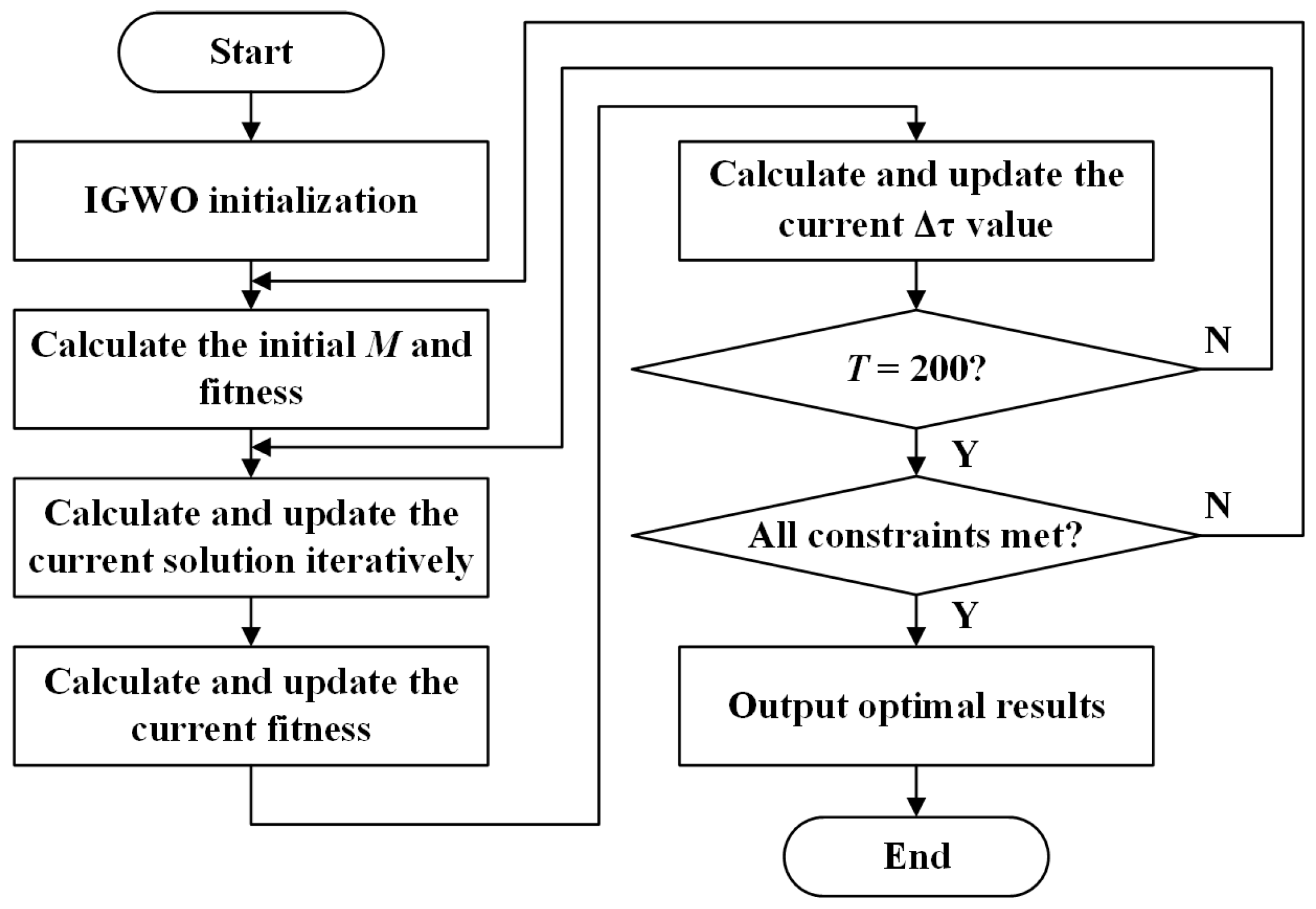
Section 4. To optimize the parameters of the MC-WPT system and complete the solution, the IGWO is introduced, and MATLAB is used. Several simulations are conducted in this study to verify two different cases: transceiver coil positive alignment and misalignment. The IGWO optimization process has a population size (
N) of 50 and a maximum number of iterations (
T) of 200.
Figure 13 depicts the flow of the optimization method for the IGWO system parameters.
The chosen metal foreign object for the simulation analysis is the smallest one, referred to as Case A among the three objects shown in
Figure 3. The purpose of this analysis is to examine the effectiveness of the proposed method in suppressing the influence of small metal foreign objects. To ensure accurate simulation results, the primary system simulation parameters are configured according to the specifications provided in
Table 1.
To ensure resonance in the system and account for the non-fixed location of the metal foreign object in the actual scene, the algorithmic constraints should be defined as follows:
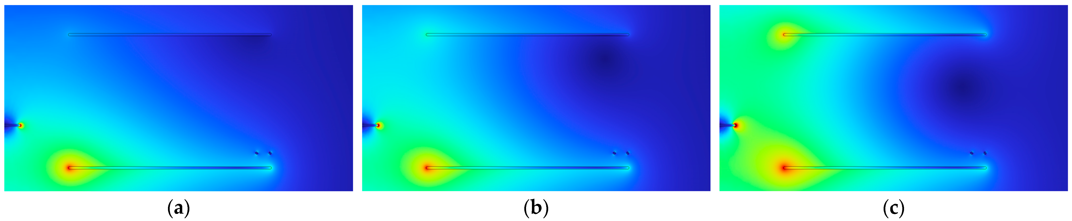
The influence of metal foreign objects on the system is modeled using the COMSOL finite element simulation when the transmitter and receiver coils are positively aligned. For the simulation, the S-S type compensation parameter, which is obtained through the optimization of both IGWO and GWO algorithms, is employed. The resulting magnetic flux density distribution in the charging region is illustrated in
Figure 14.
As depicted in
Figure 14, without algorithmic optimization, the magnetic flux density in the charging region exhibits an uneven distribution due to the influence of metal foreign objects. However, upon incorporating algorithmic optimization, the influence of metal foreign objects on the magnetic flux density distribution in the charging region is significantly mitigated. Notably, the magnetic flux density distribution in the charging region becomes more uniform after introducing the IGWO optimization compared to that of the GWO. A further comparison of the optimization effects of the two algorithms is conducted, with the results presented in
Figure 15.
The intervention of metal foreign object at 0.3 s leads to a sharp decline in output power, as illustrated in
Figure 15. With an increasing number of iterations, IGWO quickly converges toward the optimal output power. The output power optimized by IGWO is 17.3% greater than that achieved by GWO. Consequently, IGWO holds a considerable advantage over GWO when it comes to suppressing the influence of metal foreign objects.
In cases where the transmitter and receiver coils are misaligned, this paper establishes four distinct horizontal offset distances (
l = 1 cm,
l = 3 cm,
l = 5 cm, and
l = 7 cm) between them. The IGWO and GWO are implemented in MATLAB to optimize the objective function, and their results are compared to assess the effectiveness of the IGWO and GWO optimization compensation parameters in mitigating the influence of metal foreign objects, as depicted in
Figure 16.
Based on the simulation results presented in
Figure 16, when there is misalignment between transmitter and receiver coils, as depicted in
Figure 16a–d, the output power optimized by IGWO is 18.1%, 16.8%, 27.5%, and 16.5% higher than that optimized by GWO for each of the four distinct horizontal offset distances. This confirms the effectiveness of the IGWO optimization compensation parameter method in suppressing the influence of metal foreign objects. Although the increase in horizontal offset distance influences the system’s transmission performance, the IGWO proposed in this paper outperforms the GWO in rapidly optimizing the compensation parameters within a specified maximum number of iterations, achieving a higher optimal system output power while adhering to the constraints.
5.2. Experimental Results
An experimental S-S type MC-WPT system platform has been constructed to further validate the proposed method’s accuracy and reliability. This system includes an inverter circuit, a DSP controller, a compensation network, and a magnetic coupling mechanism. The DSP controller is responsible for signal acquisition and algorithm implementation. The magnetic coupling mechanism consists of transmitter and receiver coils, which are circular coils made from Leeds wire. The detection coil, positioned as depicted in
Figure 4, is a two-turn circular coil. The system’s mutual inductance is evaluated using a Chroma 11050-5M high-frequency LCR tester (Chroma ATE Inc., Taiwan, China), and the load voltage is measured with a Tektronix MSO 2024B oscilloscope (Tektronix, Beaverton, OR, USA). Load current assessment is conducted using an RP1001C current probe. The experimental S-S type MC-WPT system platform is illustrated in
Figure 17, with the parameters outlined in
Table 1.
The experiments aim to quantify the effects of metal foreign objects based on the changes in Δ
τ induced by the intervention of these foreign objects. To closely align with practical application scenarios, three metal foreign objects displayed in
Figure 18 have been chosen for the experiment. These three metal foreign objects include steel-core coins (Case A), cylindrical copper-like rods with an approximate height of 8.5 cm (Case B), and aluminum cans (Case C).
The experiment involved adjusting the transmitter and receiver coils to achieve a positive alignment. The selected steel-core coin (Case A), depicted in
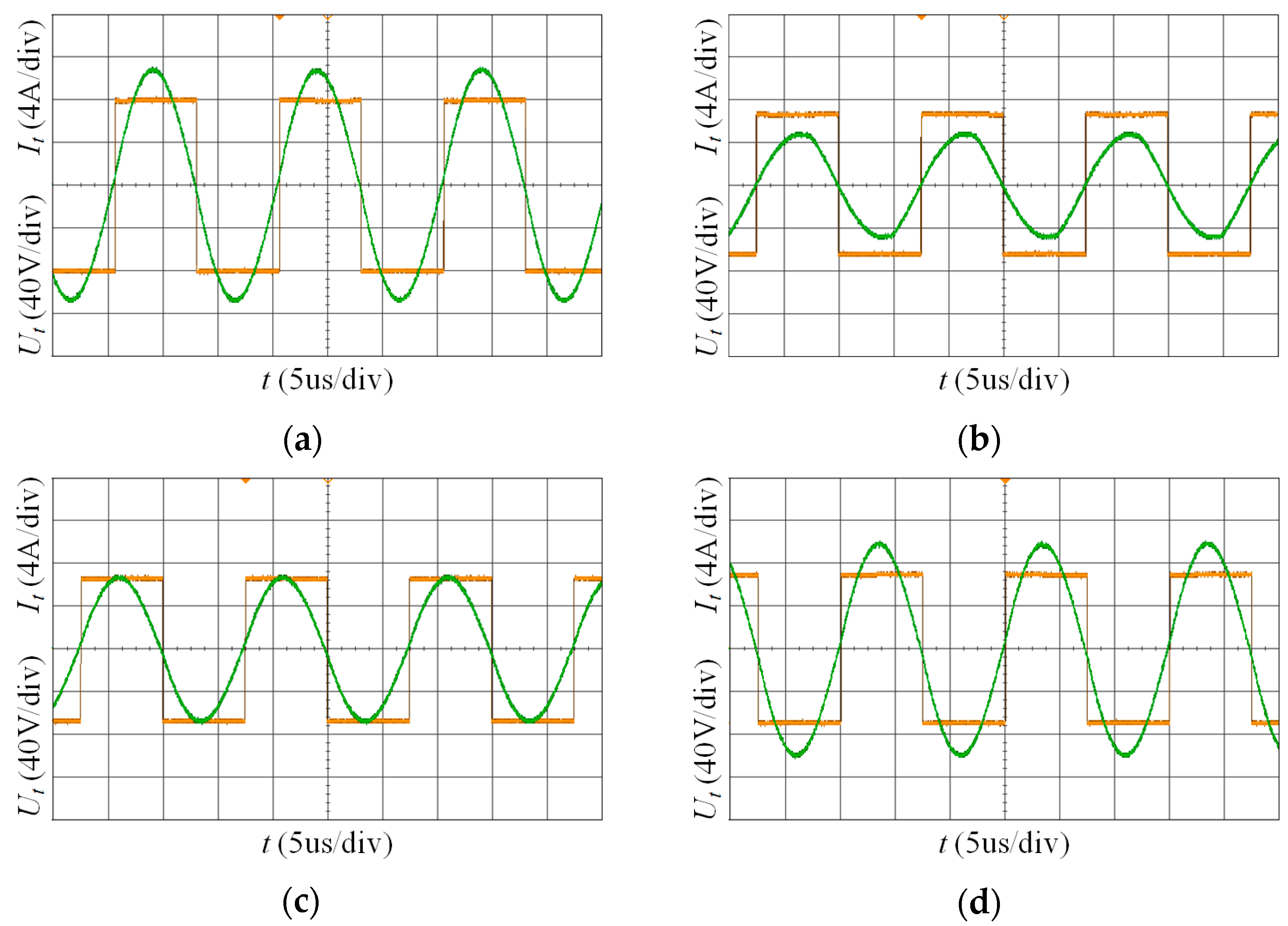
Figure 18 as the smallest among the three metal foreign objects, was used to assess the effectiveness of the proposed method in mitigating the influence of small-volume metal foreign objects. Waveforms were measured for the inverter output without the optimization algorithm, as well as for the waveforms unaffected by foreign objects and affected by Case A, as shown in
Figure 19a and
Figure 19b respectively. Compensation parameters were optimized using GWO and IGWO, resulting in optimized inverter waveforms depicted in
Figure 19c and
Figure 19d, respectively. By comparing the optimized experimental waveforms, it is evident that the IGWO significantly outperforms the GWO in suppressing the influence of metal.
The IGWO-optimized compensation parameters demonstrate a clear suppression under the influence of Case A, outperforming the GWO in terms of optimization effectiveness. The experimental process is subsequently repeated for Case B and Case C, respectively. The system output power for the three metal foreign objects is experimentally measured for no algorithm optimization, GWO optimization, and IGWO optimization, as presented in
Figure 20.
When the transmitter and receiver coils are aligned positively,
Figure 20 shows that both GWO and IGWO optimizations result in a significant improvement in the output power. A comparison of the output power without algorithmic optimization under the influence of three types of metal foreign objects reveals that the output power after IGWO optimization is higher compared to GWO, indicating that IGWO’s effect on suppressing the influence of metal foreign objects is notably superior to that of GWO.
Subsequently, to create misalignment with a horizontal offset distance of
l = 5 cm, the relative positions of the transmitter and receiver coils were adjusted, and Case A was chosen for the experiment.
Figure 21 displays the optimized inverted waveforms using GWO and IGWO to optimize the compensation parameters.
As evident from
Figure 21, a comparison of the inverted output waveforms reveals that the current amplitude decreases when the transmitter and receiver coils are misaligned. Despite this, the IGWO still significantly outperforms the GWO in terms of suppressing metal influence. Based on the optimal solution provided by the IGWO, the corresponding compensation parameters for suppressing the influences of Case A, Case B, and Case C without offset, as well as the compensation parameter for suppressing the influence of Case A with a 5 cm offset, are obtained, as showcased in
Table 2.
In the final stage of the experiment, with the transmitter and receiver coils maintained at a horizontal offset distance of
l = 5 cm, the metal foreign objects depicted in
Figure 17 were placed in the charging region to monitor the change in Δ
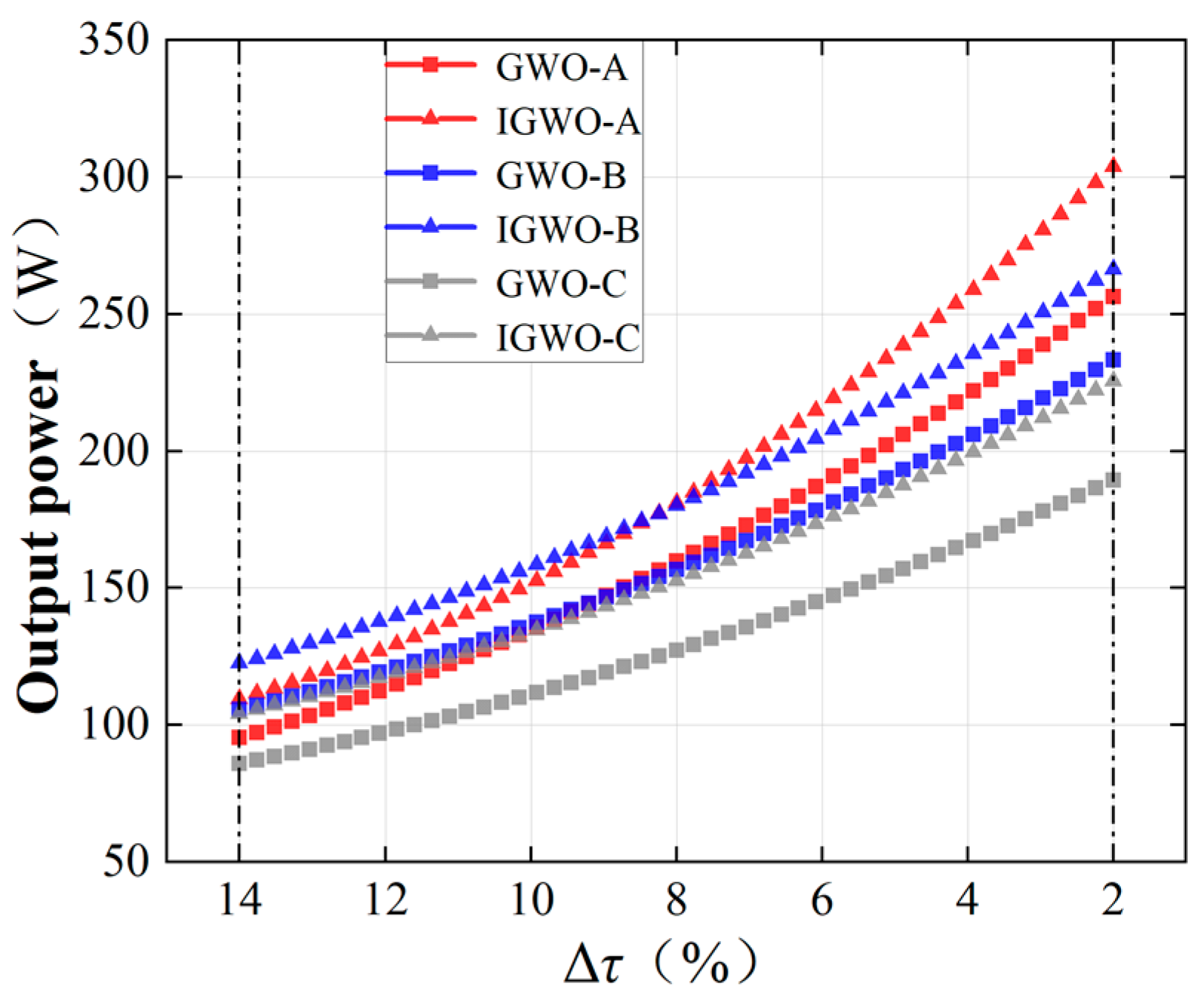
τ. Following the intervention of the metal foreign objects, the IGWO was implemented to suppress their effects, while the GWO was introduced as a control experiment. The three different metal foreign object interventions were investigated separately, and after several trials, three sets of experimental result curves were obtained: GWO-A and IGWO-A, GWO-B and IGWO-B, as well as GWO-C and IGWO-C. The comparative results of the output power within the same Δ
τ optimization interval are presented in
Figure 22.
Within the chosen Δ
τ optimization interval, both IGWO and GWO can be employed to suppress the influence of metal foreign objects while maintaining a relatively small Δ
τ, as seen in
Figure 22. A comparison of the effects reveals that the IGWO yields a higher overall output power. The optimization using IGWO further satisfies the load power demand and minimizes power loss, even though the system’s output power is inevitably partially reduced due to the influence of foreign objects and offset.
Based on the experimental results, it can be concluded that the IGWO, which introduces improved convergence factor update formulae, is more effective in suppressing the influence of metal foreign objects and reducing the system’s output power loss compared to the GWO.
6. Discussion
This paper utilizes the IGWO to optimize the compensation topology parameters of the system. Additionally, the detection coil device is employed to assist in suppressing the influence of metal foreign objects. By calibrating the mutual inductance M’ of the abnormal state system with reference to the mutual inductance M of the normal state system, the method effectively suppresses the influence of metal foreign objects. Importantly, the method remains effective in suppressing the influence of metal foreign objects even when the transmitter and receiver coils are misaligned.
The prevalent approach for suppressing the influence of metal foreign objects in MC-WPT systems involves active suppression. This entails winding detection coils in the opposite direction around the exterior of the transmitter and receiver coils and powering it on, thereby attenuating the magnetic flux passing through the metal foreign object and diminishing the coupling between the transmitter coil and the metal foreign object. To evaluate the reduction in output power drop, this study selected the experimental results of suppressing aluminum metal at the same power level from Ref. [
23] as a benchmark. When compared to the results depicted in
Figure 20, the maximum drop amplitude of 16.7% was notably lower than the 35.8% observed in the reference group, as demonstrated in
Table 3. Consequently, the methodology proposed in this paper offers significant advantages in curtailing the output power drop induced by metal foreign objects.
In comparison to the active suppression technique, the proposed method offers several distinct advantages. Firstly, when the power level changes, the active suppression method necessitates replacing detection coils of varying sizes and altering their installation positions. In contrast, the proposed method simply requires increasing or decreasing the number of turns in the detection coil, thereby enhancing its universality and reducing the design and implementation costs.
Secondly, regarding method complexity, the active suppression method demands the reassessment of the detection coil’s size and number of turns based on the requirements of different applications. Additionally, it requires determining the winding technique and installation position to mitigate the influence of equivalent internal resistance. Conversely, the proposed method only needs to adjust the detection coil’s size to align it with the transmitter and receiver coils and redefine the IGWO’s constraint conditions, effectively simplifying the design and application.
Lastly, as swarm intelligence optimization algorithms have emerged as a crucial means for rapidly and efficiently solving engineering challenges, the combination of metal foreign object influence suppression methods with system parameter optimization holds great promise for future scientific advancements and is worthy of further investigation and research.
7. Conclusions
A method for suppressing the influence of metal foreign objects in MC-WPT systems is proposed in this paper. Theoretical mathematical models for mutual inductance and output power are derived, with the mutual inductance deviation measure Δτ being defined. A circuit model incorporating detection coils is developed. To streamline the design of the detection coils and confirm the quantification of the influence of metal foreign objects on the system, a simulation model is constructed using the finite element simulation software COMSOL6.1, Version 6.1.0.357. Three distinct types of metal foreign objects are analyzed in the simulation model.
In this paper, the issue of metal foreign object influence suppression in the system can be addressed through system parameter optimization, based on theoretical and simulation analysis. Factors such as the influence of metal foreign object intervention on the mutual inductance deviation measure when the transmitter and receiver coils are misaligned are considered, and decision variables and constraints are determined. The topology compensation parameters are optimized and solved by introducing the improved convergence factor updating formula of the IGWO within a finite number of iterations to achieve the optimal output power swiftly and accurately. Simulation and experimental outcomes demonstrate that the proposed method effectively suppresses the influence of metal foreign objects, and the optimization effect of IGWO has evident advantages over GWO.
To accomplish metal foreign object influence suppression, the proposed method primarily relies on IGWO, which swiftly and precisely optimizes system parameters. However, in practical application scenarios with significant variations in power levels and external environments, accurate optimization of IGWO becomes challenging through adjustments to constraint conditions and other techniques. As a result, the effectiveness of the proposed method in suppressing metal foreign object influence is diminished. To overcome these limitations, future research will focus on enhancing IGWO’s accurate optimization by implementing strategies such as refining the detection coil structure and incorporating system control modules.
In conclusion, this paper proposes a method that effectively suppresses the influence of metal foreign objects in MC-WPT systems. This method is particularly relevant for low-power device applications, including autonomous guided transportation vehicles, underwater autonomous vehicles, and smart homes.
Author Contributions
Conceptualization, W.H. and Y.Z.; methodology, Y.Z.; software, Y.Z.; validation, Y.Z., Y.H. and J.H.; formal analysis, W.H. and Y.Z.; investigation, Y.C. and C.M.; resources, Y.C. and C.M.; writing—original draft preparation, Y.Z.; writing—review and editing, W.H. and Y.Z.; visualization, Y.Z.; supervision, Y.C. All authors have read and agreed to the published version of the manuscript.
Funding
This research was funded by Southern Power Grid Corporation Wireless Power Transmission Joint Laboratory through the Opening Foundation Projects under grant number GXKJXM20210149 and the Hubei University of Technology Doctoral Research Project under grant number BSQD2020012.
Data Availability Statement
Data are contained within the article.
Conflicts of Interest
The authors declare no conflict of interest.
Abbreviations
| WPT | Wireless Power Transfer |
| MC-WPT | Magnetic field Coupled Wireless Power Transfer |
| MOD | Metal Object Detection |
| IGWO | Improved Gray Wolf Optimizer |
| GWO | Gray Wolf Optimizer |
| Δτ | The mutual inductance deviation measure |
| Ld | The self-inductance of the detection coil |
| Rd | The internal resistance of the detection coil |
| Lp | The self-inductance of the transmitter coil |
| Rd | The internal resistance of the transmitter coil |
| Cp | The compensation capacitance of the transmitter coil |
| Ls | The self-inductance of the receiver coil |
| Rs | The internal resistance of the receiver coil |
| Cs | The compensation capacitance of the receiver coil |
| Ip | The current of the transmitter coil in normal state |
| Is | The current of the receiver coil in normal state |
| Id | The current of the detection coil |
| Up | The input voltage |
| Udi | The induced voltage of the ith detection coil |
| Re | The internal resistance of the load |
| M | The system mutual inductance |
| Mpi | The coupling mutual inductance of the detection coil to the transmitter coil |
| Msi | The coupling mutual inductance of the detection coil to the receiver coil |
| Lm | The self-inductance of the metal equivalent loop |
| Rm | The internal resistance of the metal equivalent loop |
| The current of the transmitter coil in abnormal state |
| The current of the receiver coil in abnormal state |
| Im | The current of the metal equivalent loop |
| Mpm | The coupling mutual inductance between the metal foreign object and the transmitter coil |
| Msm | The coupling mutual inductance between the metal foreign object and the receiver coil |
| X(t) | The position of the prey |
| D | The distances between the prey and the corresponding wolf |
| μ0 | The vacuum permeability |
| N1 | The number of turns for the transmitter coils |
| N2 | The number of turns for the receiver coils |
| r12 | The relative distance between the transmitter and receiver coils |
References
- Detka, K.; Górecki, K. Wireless Power Transfer—A Review. Energies 2022, 15, 7236. [Google Scholar] [CrossRef]
- Guo, H.; Zhang, X.; Yang, Q.; Sha, L.; Wang, F.; Zhu, Z. Review of Research and Application of Spatial Omnidirectional Wireless Power Transmission Technology. Proc. CSEE 2022, 42, 9006–9022. (In Chinese) [Google Scholar] [CrossRef]
- Mahesh, A.; Chokkalingam, B.; Mihet-Popa, L. Inductive Wireless Power Transfer Charging for Electric Vehicles–A Review. IEEE Access 2021, 9, 137667–137713. [Google Scholar] [CrossRef]
- Chen, Y.; Yang, B.; Peng, Y.; Lu, Y.; Zhang, Z.; Mai, R.; He, Z. Review of Anti-Misalignment Technology in Inductive Wireless Power Transfer System. Proc. CSEE 2023, 43, 5537–5557. (In Chinese) [Google Scholar] [CrossRef]
- Xu, F.F.; Wei, S.G.; Yuan, D.; Li, J.Q. Review on Key Technologies and Development of Magnetic Coupling Resonant-Dynamic Wireless Power Transfer for Unmanned Ground Vehicles. Electronics 2023, 12, 1506. [Google Scholar] [CrossRef]
- Lu, C.H.; Huang, X.T.; Tao, X.; Liu, X.; Rong, C.; Zeng, Y.; Liu, M. Design and Analysis of an Omnidirectional Dual-Band Wireless Power Transfer System. IEEE Trans. Antennas Propag. 2021, 69, 3493–3502. [Google Scholar] [CrossRef]
- Chen, W.; Song, Y.; Yan, X. Integration of Resonant Wireless Energy Supply LCL-LCL for Cardiac Pacemaker. Trans. China Electrotech. Soc. 2022, 37, 2924–2935. (In Chinese) [Google Scholar] [CrossRef]
- Jin, Y.; Xu, J.; Wu, S.X.; Xu, L.; Yang, D.; Xia, K. Bus Network Assisted Drone Scheduling for Sustainable Charging of Wireless Rechargeable Sensor Network. J. Syst. Archit. 2021, 116, 1383–7621. [Google Scholar] [CrossRef]
- Xu, F.L.; Huang, H.C. Frequency Selection for Underwater Wireless Power Transfer Based on the Analysis of Eddy Current Loss. Aeu-Int. J. Electron. Commun. 2023, 163, 154618. [Google Scholar] [CrossRef]
- Gou, X.G.; Sun, Z.J.; Huang, K.Y. UAV-Aided Dual-User Wireless Power Transfer: 3D Trajectory Design and Energy Optimization. Sensors 2023, 23, 2994. [Google Scholar] [CrossRef]
- Kodeeswaran, S.; Gayathri, M.N.; Sanjeevikumar, P.; Peña-Alzola, R. High-Power Converters and Challenges in Electric Vehicle Wireless Charging—A Review. IETE J. Res. 2023, 1–20. [Google Scholar] [CrossRef]
- Zhang, X.; Xing, Z.; Xue, M.; Yang, Q.; Sun, Y. Overview of Foreign Object Detection in Wireless Power Transfer System. Trans. China Electrotech. Soc. 2022, 37, 793–807. (In Chinese) [Google Scholar] [CrossRef]
- Su, Y.; Hou, X.; Dai, X. Review of Foreign Object Detection Technology in Magnetic Coupling Wireless Power Transfer System. Proc. CSEE. 2021, 42, 715–727. (In Chinese) [Google Scholar] [CrossRef]
- Xia, J.; Yuan, X.; Li, J.; Lu, S.; Cui, X.; Li, S.; Fernández-Ramírez, L.M. Foreign Object Detection for Electric Vehicle Wireless Charging. Electronics 2020, 9, 805. [Google Scholar] [CrossRef]
- Lu, J.; Zhu, G.; Mi, C.C. Foreign Object Detection in Wireless Power Transfer Systems. IEEE Trans. Ind. Appl. 2022, 58, 1340–1354. [Google Scholar] [CrossRef]
- Luo, X.Q.; Cai, S.K.; Liu, Z.Z.; Hou, Y.; Xie, Y.; Sun, S.; Ding, R.; Feng, G.; Wei, X. Research on Metal Foreign Object Detection Method in Wireless Charging System of Electric Vehicle Based on Array Detection Coil. Energies 2023, 16, 5437. [Google Scholar] [CrossRef]
- Niu, S.Y.; Zhang, C.; Shi, Y.J.; Niu, S.; Jian, L. Foreign Object Detection Considering Misalignment Effect for Wireless EV Charging System. ISA Trans. 2022, 130, 655–666. [Google Scholar] [CrossRef]
- Yang, Z.; Xia, C.; Zhao, S.; Li, H.; Peng, Y.; Xiang, L.; Li, W. Non-blind zone MOD method based on incomplete compensation of detection coil for EV. Proc. CSEE 2022, 42, 7363–7375. (In Chinese) [Google Scholar] [CrossRef]
- Jeong, S.Y.; Kwak, H.G.; Jang, G.C.; Choi, S.Y.; Rim, C.T. Dual-Purpose Nonoverlapping Coil Sets as Metal Object and Vehicle Position Detections for Wireless Stationary EV Chargers. IEEE Trans. Power Electron. 2018, 33, 7387–7397. [Google Scholar] [CrossRef]
- Jeong, S.Y.; Thai, V.X.; Park, J.H.; Rim, C.T. Self-Inductance-Based Metal Object Detection With Mistuned Resonant Circuits and Nullifying Induced Voltage for Wireless EV Chargers. IEEE Trans. Power Electron. 2019, 34, 748–758. [Google Scholar] [CrossRef]
- Du, K.; Zhu, G.; Lu, J.; Pang, M. Metal Object Detection Method in Wireless Electric Vehicle Charging System. J. Zhejiang Univ. (Eng. Sci.) 2022, 56, 56–62+74. (In Chinese) [Google Scholar]
- Zhong, W.X.; Xiang, F.; Hu, C.S. Metal Object Detection With Detection Coils Perpendicular to Power Coils for Wireless Power Transfer Systems. IEEE Trans. Power Electron. 2023, 38, 10530–10534. [Google Scholar] [CrossRef]
- Su, Y.; Liu, J.; Wang, Z.; Xin, D.; Jian, Y. Influence Analysis of Metal in the Same Plane with Pickup Coil on Magnetic Coupler and Suppression Method. Trans. China Electrotech. Soc. 2021, 42, 715–727. (In Chinese) [Google Scholar] [CrossRef]
- Garcia-Martin, J.; Gomez-Gil, J.; Vazquez-Sanchez, E. Non-Destructive Techniques Based on Eddy Current Testing. Sensors 2011, 11, 2525–2565. [Google Scholar] [CrossRef] [PubMed]
- Paul, K.; Sinha, P.; Bouteraa, Y.; Skruch, P.; Mobayen, S. A Novel Improved Manta Ray Foraging Optimization Approach for Mitigating Power System Congestion in Transmission Network. IEEE Access 2023, 11, 10288–10307. [Google Scholar] [CrossRef]
- Zand, S.J.; Mobayen, S.; Gul, H.Z.; Molashahi, H.; Nasiri, M.; Fekih, A. Optimized Fuzzy Controller Based on Cuckoo Optimization Algorithm for Maximum Power-Point Tracking of Photovoltaic Systems. IEEE Access 2022, 10, 71699–71716. [Google Scholar] [CrossRef]
- Cao, Y.; Li, T.; He, T.; Wei, Y.; Li, M.; Si, F. Multiobjective Load Dispatch for Coal-Fired Power Plants under Renewable-Energy Accommodation Based on a Nondominated-Sorting Grey Wolf Optimizer Algorithm. Energies 2022, 15, 2915. [Google Scholar] [CrossRef]
- Mirjalili, S.; Mirjalili, S.M.; Lewis, A. Grey Wolf Optimizer. Adv. Eng. Softw. 2014, 69, 46–61. [Google Scholar] [CrossRef]
Figure 1.
MC-WPT system normal state circuit model.
Figure 1.
MC-WPT system normal state circuit model.
Figure 2.
MC-WPT system abnormal state circuit model.
Figure 2.
MC-WPT system abnormal state circuit model.
Figure 3.
Geometric modeling of metal foreign objects.
Figure 3.
Geometric modeling of metal foreign objects.
Figure 4.
Schematic diagram of the magnetic coupling mechanism with detection coils.
Figure 4.
Schematic diagram of the magnetic coupling mechanism with detection coils.
Figure 5.
Geometric model of magnetic coupling mechanism with detection coils.
Figure 5.
Geometric model of magnetic coupling mechanism with detection coils.
Figure 6.
The variation of Δτ with different detection coil turns.
Figure 6.
The variation of Δτ with different detection coil turns.
Figure 7.
The 2D axisymmetric surface magnetic flux density distribution. (a) magnetic flux density distribution under normal state; (b) magnetic flux density distribution under abnormal state.
Figure 7.
The 2D axisymmetric surface magnetic flux density distribution. (a) magnetic flux density distribution under normal state; (b) magnetic flux density distribution under abnormal state.
Figure 8.
Δτ values under the influence of metal foreign objects.
Figure 8.
Δτ values under the influence of metal foreign objects.
Figure 9.
Comparison of the a update formula before and after improvement.
Figure 9.
Comparison of the a update formula before and after improvement.
Figure 10.
Schematic diagram of the magnetic coupling mechanism with the misalignment.
Figure 10.
Schematic diagram of the magnetic coupling mechanism with the misalignment.
Figure 11.
Geometric model of the magnetic coupling mechanism with the misalignment.
Figure 11.
Geometric model of the magnetic coupling mechanism with the misalignment.
Figure 12.
The variation of Δτ with the misalignment.
Figure 12.
The variation of Δτ with the misalignment.
Figure 13.
The improved IGWO solution process.
Figure 13.
The improved IGWO solution process.
Figure 14.
Magnetic flux density distribution between transmitter and receiver coils: (a) no algorithm optimization effect; (b) GWO optimization effect; (c) IGWO optimization effect.
Figure 14.
Magnetic flux density distribution between transmitter and receiver coils: (a) no algorithm optimization effect; (b) GWO optimization effect; (c) IGWO optimization effect.
Figure 15.
Optimization results of IGWO and GWO.
Figure 15.
Optimization results of IGWO and GWO.
Figure 16.
IGWO and GWO convergence curve comparison.
Figure 16.
IGWO and GWO convergence curve comparison.
Figure 17.
The experimental S-S MC-WPT system platform.
Figure 17.
The experimental S-S MC-WPT system platform.
Figure 18.
Different metal foreign objects.
Figure 18.
Different metal foreign objects.
Figure 19.
The waveforms of inverter output at transceiver coils in the alignment. (a) without foreign object and without algorithmic optimization, (b) without algorithmic optimization, (c) after GWO optimization, (d) after IGWO optimization.
Figure 19.
The waveforms of inverter output at transceiver coils in the alignment. (a) without foreign object and without algorithmic optimization, (b) without algorithmic optimization, (c) after GWO optimization, (d) after IGWO optimization.
Figure 20.
Output power of coils with the alignment.
Figure 20.
Output power of coils with the alignment.
Figure 21.
The waveforms of inverter output in the misalignment. (a) after GWO optimization for the influence, (b) after IGWO optimization for the influence.
Figure 21.
The waveforms of inverter output in the misalignment. (a) after GWO optimization for the influence, (b) after IGWO optimization for the influence.
Figure 22.
Comparison of inhibition effect of IGWO and GWO.
Figure 22.
Comparison of inhibition effect of IGWO and GWO.
Table 1.
Primary system simulation parameters.
Table 1.
Primary system simulation parameters.
| Name | Value |
|---|
| System frequency (f) | 85 kHz |
| Load resistor (Re) | 20 Ω |
| Range of compensation capacitance (Cp, Cs) | [30 nF, 120 nF] |
| Range of mutual inductance between transmitter coil and detection coil (Mpi) | [10 μH, 20 μH] |
Range of mutual inductance between metal foreign
objects and coils (Mpm, Msm) | [20 μH, 40 μH] |
| Metal foreign object’s Self-inductance (Lm) | 10 μH |
| Metal foreign object’s resistor (Rm) | 1 Ω |
Table 2.
The optimal solution corresponds to the compensation parameters.
Table 2.
The optimal solution corresponds to the compensation parameters.
| Parameter | l = 0 | l = 5 cm |
|---|
| Case A | Case B | Case C | Case A |
|---|
| Cp (nF) | 51.32 | 53.39 | 59.36 | 43.50 |
| Cs (nF) | 47.68 | 44.51 | 49.87 | 40.27 |
| Lp (uH) | 70.88 | 68.52 | 65.18 | 83.06 |
| Ls (uH) | 77.16 | 82.58 | 73.42 | 89.62 |
Table 3.
Comparison of the output power drop.
Table 3.
Comparison of the output power drop.
| Parameter | Experimental Group | Benchmark in [23] |
|---|
| Case A | Case B | Case C | Metal Object (Al) |
|---|
| Output power drop (%) | 4.3 | 9.8 | 16.7 | 35.8 |
| Disclaimer/Publisher’s Note: The statements, opinions and data contained in all publications are solely those of the individual author(s) and contributor(s) and not of MDPI and/or the editor(s). MDPI and/or the editor(s) disclaim responsibility for any injury to people or property resulting from any ideas, methods, instructions or products referred to in the content. |
© 2023 by the authors. Licensee MDPI, Basel, Switzerland. This article is an open access article distributed under the terms and conditions of the Creative Commons Attribution (CC BY) license (https://creativecommons.org/licenses/by/4.0/).


