1. Introduction
As a result of the PRASS III project, a system for monitoring the geometric parameters of powered roof supports has been developed. The research work undertaken in the PRASS III (Productivity and safety of shield support, grant 752504 (2017)) project was supported by the EU Research Fund for Coal and Steel (RFCS) as well as the Ministry of Science and Higher Education. The system enables the measurement of powered roof supports and their individual components, contributing to enhanced safety for both personnel and machinery during the hard coal mining process. Incorporating these data allows for anticipating roof rock collapses in the longwall face and implementing preventive measures. This paper provides details on the system’s measurement accuracy, emphasizing its significance in the absence of proper inclinometer calibration under real conditions.
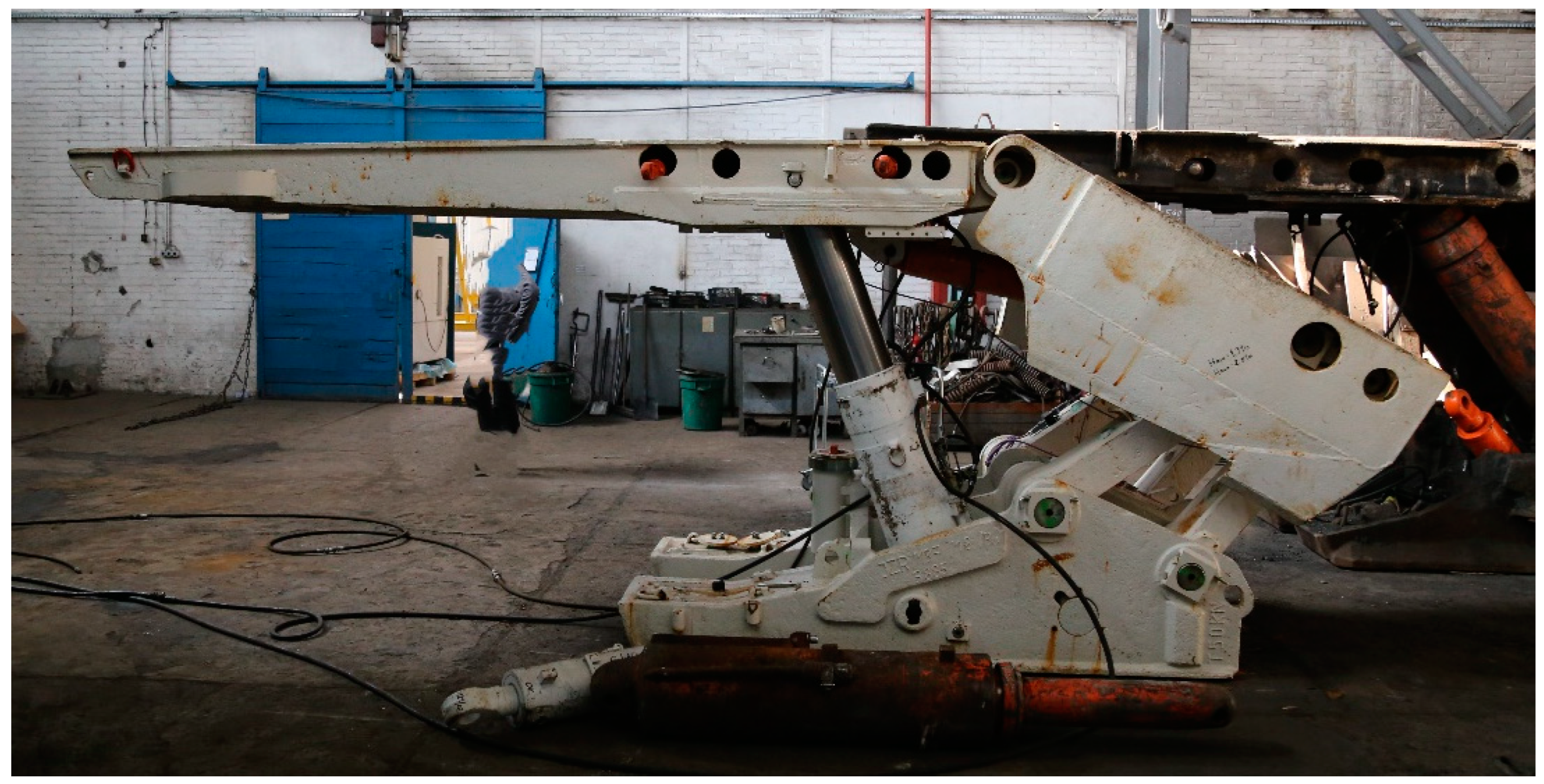
1.1. Section of Powered Roof Support
Longwall powered roof supports are part of the equipment of longwall mining complexes. In addition to the powered roof support, the complex also includes a shearer loader, a longwall conveyor and other technical equipment. An example of a powered roof support is shown in
Figure 1.
The powered roof support selected depends on the mining geological parameters of a given longwall [
1,
2,
3,
4,
5]. Prior to the commissioning of a powered roof support, it is tested in an accredited laboratory [
1,
6]. The selected repaired powered roof supports are also tested. Powered roof supports can be controlled manually or automatically. Automatic control is used in the case of automated mining complexes [
7], in which the operation of the mining machine, the powered roof support and the conveyor is synchronized.
1.2. Justification for Building a Geometry Monitoring System
The developed system for measuring the geometry of powered roof supports consists of inclinometers installed on the structural components of the roof support and a central unit collecting data from the sensors and transmitting them via a radio network to the visualization software. The inclinometers have been developed to be universal and can be used on various types of powered roof supports and other machines. Inclinometers can be installed both on new and repaired roof supports by welding the mounting brackets.
The primary objective was to equip roof supports with geometry measurement devices in addition to pressure measurements in the hydraulic legs (main hydraulic cylinders) to obtain additional diagnostic data on the impact of the rock mass pressure on the roof support. This information can be used in the process of predicting the roof fall—the uncontrolled detachment of roof rock. By measuring the roof support geometry it is possible to determine [
4] the load-bearing capacity of rock mass layers overhanging behind shields, the self-supporting capacity of the first roof layer, the distribution of support capacity along the canopy length and the transverse and longitudinal inclinations of a longwall panel.
Pressure in the hydraulic system is a parameter usually monitored during longwall powered roof support operation. There is ongoing research on using information on hydraulic legs pressure to identify the technical condition of a roof support and the interaction of the current conditions of the roof support with the rock mass. The paper [
8] presents the use of pressure monitoring in hydraulic legs to generate an early warning of severe roof weightings. The authors presented the SSRI (Status of Shield and Roof IntelliSense) software package. However, the analyses did not take into account the geometry of the powered roof supports. The paper [
9] proposed a universal composite longwall index. The index was developed based on numerical simulations of the interaction between a powered roof support and a roadway roof. The analyses took into account the pressure in the hydraulic legs but did not take into account the roof support geometry.
There is also ongoing research related to the modeling of the interaction between a powered roof support and a rock mass [
10]. This research work most often concerns simulating the stress of roof supports depending on mining and geological conditions, such as geological structure, and information about previous mining operations in the area [
11]. The publication [
12] presents a mechanical analysis of the impact of a rock mass on a powered roof support. The roof support was subjected to loads from the roof and the loading system depended on the type of roof—roof rock arrangement. The presented distribution of forces affected the kinematic chain of the roof support. The relationships presented in the publication indicate that by measuring the geometry of the powered roof support, it will be possible to analyze the action of rock mass on the roof support.
The paper [
13] presents the influence of the canopy ratio of a powered roof support on longwall working stability. Based on the results of the performed model testing as well as the analyses and in situ observation for the analyzed case in coal seam, the authors presented the following conclusions: the results of the numerical calculations confirmed that the longwall panel stability depends not just on the powered support capacity, but also on the correct geometrical parameters of the powered support. The relationship between rocks and powered supports was also presented in [
14,
15,
16].
1.3. Justification of the Research Problem—The Assembly Problem
During testing of the developed system, a number of technical problems were encountered with the installation of the inclinometers. In the case of new powered roof supports, mounting brackets have to be installed. Workshop tolerances of the welded structure are the problem—the inclinometer mounts are welded on the inclined sheets forming the roof support structure. The angles between the welded plates are not repeatable, and installing the inclinometer on different roof supports gives different readings despite having the same alignment. The roof support clearances at the pins connecting the roof support components affect the forces. When monitoring the kinematic chain of the roof support, these clearances cause distortions in the measurements. These clearances depend on the load to the roof support.
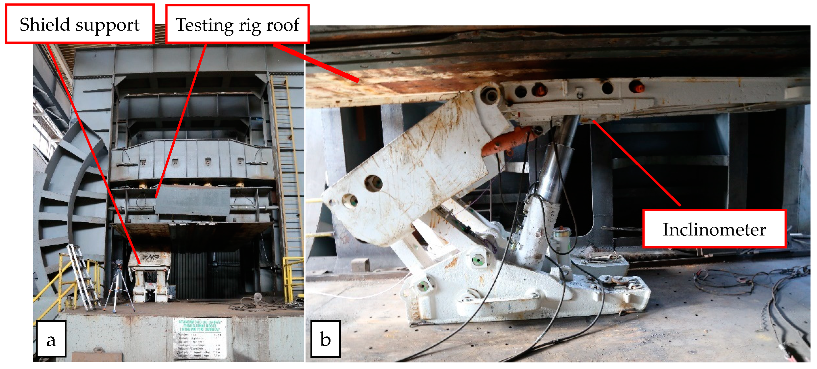
A JZR 13/28 POZ powered roof support was used to test the monitoring system on the test bench. The JZR 13/28 POZ roof support was strutted into a rigid test bench frame (
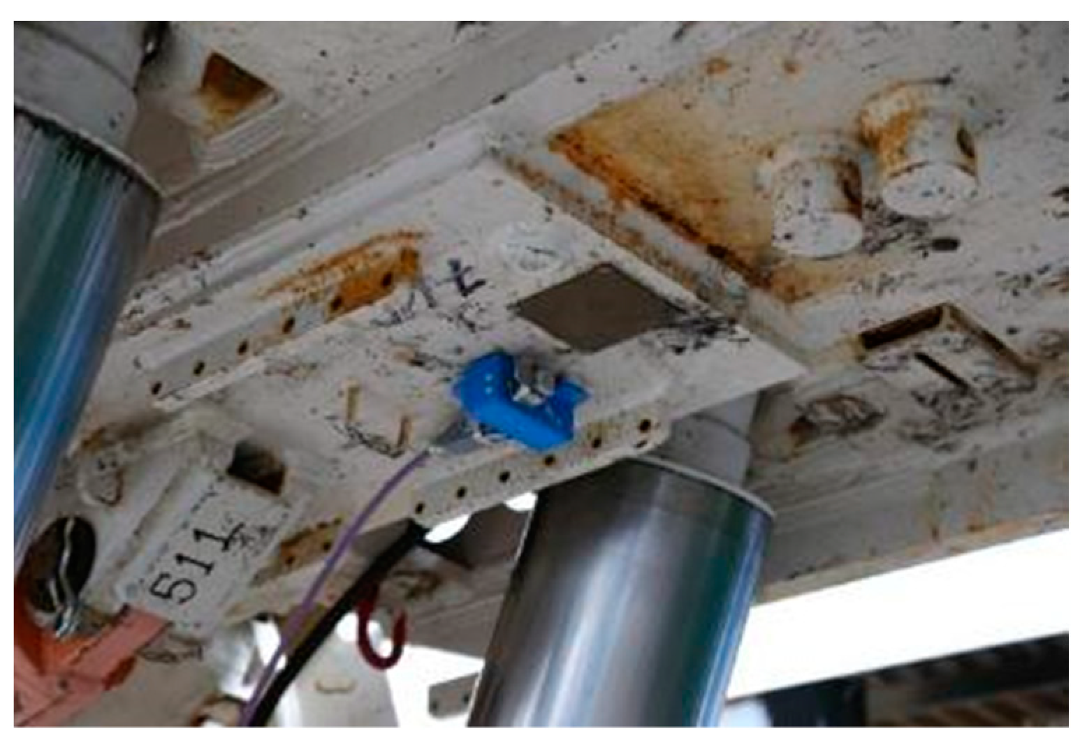
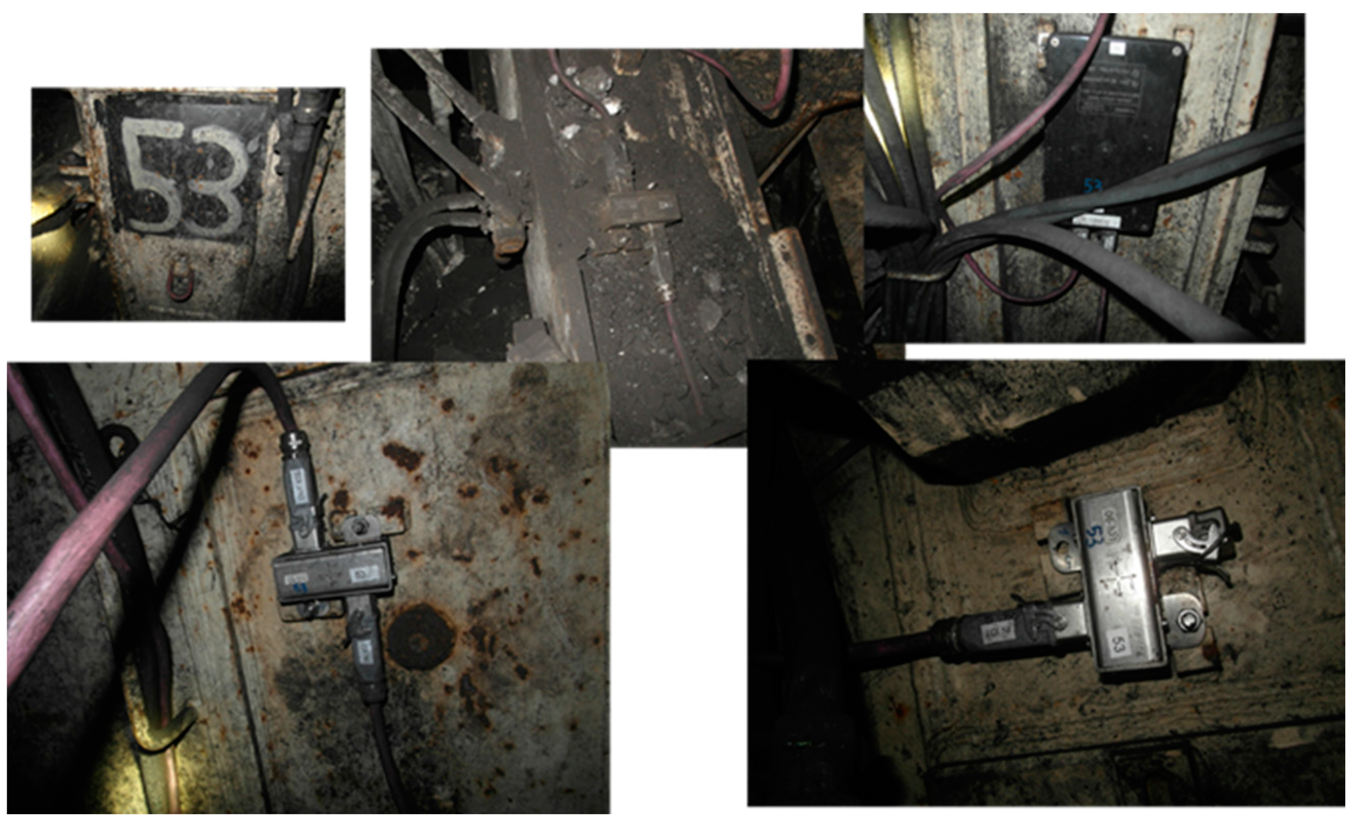
Figure 2). The place of installation of the inclinometer is shown in
Figure 3.
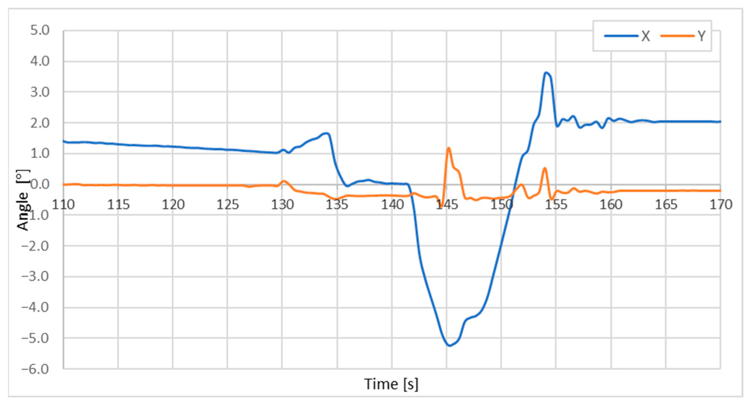
Figure 4 shows the change in the canopy angle during the laboratory test, setting the roof support to load, recorded by the developed inclinometer. Setting the roof support to load consisted of applying a nominal hydraulic pressure of 24 MPa to the roof support legs. When nominal pressure was reached in the roof support legs, clearance of the roof support was reset from 130 to 140 s of measurement. This was followed by resetting the clearance in the test stand from 140 to 160 s. After 160 s, the roof support legs were supplied with nominal pressure and all clearances were reset.
It can be seen from
Figure 4 that the arrangement of the components of the powered roof support depended on the load. The roof support, when set to nominal pressure, reset the clearances on the pins.
The inclinometer was mounted to the special brackets welded to the roof support. However, the brackets were not subjected to mechanical treatment (to a given axis) after the assembly of the roof support. As the brackets were made of standard steel, they were coated with a varnish to protect them from corrosion.
Measurements of the angles of each assembly and knowledge of the dimensions should unambiguously determine the dimensions (height) of the powered roof support. Analysis of the errors present in the real object showed the difficulty of determining the unambiguous geometry of the powered roof support.
The most significant aspects that make measurement difficult include:
Manufacturing errors in the roof support assemblies (canopy, gob shield, lemniscate link and base);
Clearances on the pins connecting the roof support assemblies;
Inaccuracies in the installation of inclinometer brackets (inaccuracies in relation to the surface of the assemblies as well as transverse perpendicularity);
Corrosion protection.
It is possible to calibrate inclinometers by assigning them to the machine at the manufacture stage. However, such a solution cannot be used in practice because roof supports are often disassembled for transport, and their assembly under target conditions does not guarantee the same configuration of components. A roof support assembled underground in a mine may consist of different components than a roof support on the manufacture line. In addition, inclinometers installed on a roof support can be destroyed during transportation. Roof supports are usually transported by truck to the mine, then transported underground by shaft hoist. Depending on the size of the roof support, they may be separated into sub-assemblies. In underground mines, roof supports are transported over several kilometers [
17]. During the transport cycle, the roof supports are repeatedly reloaded and exposed to mechanical damage. For this reason, all of the electronic and hydraulic equipment is installed at the destination site. In the case of repaired roof supports, the unevenness of the sheet metal surface resulting from corrosion and the cleaning techniques used—e.g., sandblasting—are added to all the problems described earlier. All these factors contribute to the fact that it is difficult to guarantee that the measurement taken is consistent with the actual position of the roof support components.
1.4. Research Problem—Is It Possible to Use Inclinometers without a Calibration?
The SSMS (Shield Support Monitoring System) was tested in a mine underground, on a real object, to find out whether it is possible to use geometry measurement without exact calibration. A technical and economic analysis of the inclinometer installation showed that carrying out a calibration process that included removing the impact of the manufacturing errors in the roof support assemblies, clearances on the pins connecting the roof support assemblies, inaccuracies in the installation of inclinometer brackets and corrosion protection is not justified. It was assumed that in the process of interpreting the interaction conditions of the roof support and the rock mass, absolute angle data and trends in angle changes are important. It was assumed that in the process of detecting the loading pattern associated with the roof fall behind the roof support, the trend would be more important than the absolute value of the angle. Instead, it is important to determine the measurement error of inclinometers during their operation on a roof support.
In the paper [
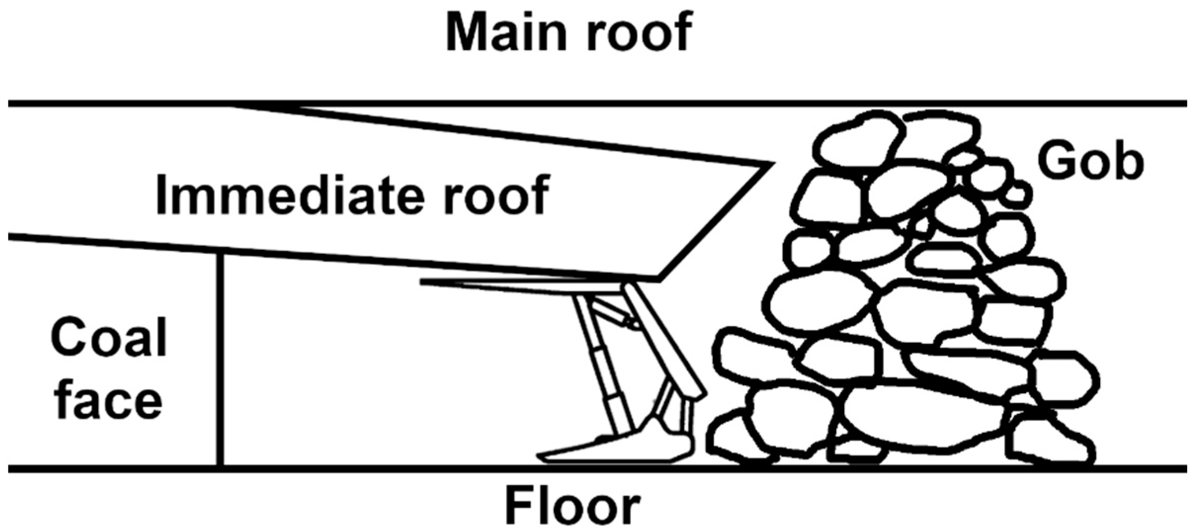
18], various roof support loading schemes are presented as experimental results. From the presented loading schemes, it can be seen that the arrangement of rocks above a roof support exerts forces that cause changes in the roof support kinematic chain. For example, the overhanging of rocks behind the roof support causes inclination of the canopy, as shown in
Figure 5. This principle is also presented in [
19].
It was assumed that the impact of the rock mass causes a change in the canopy position. The current value of the angle was taken as the starting point, accepting inaccuracies resulting from lack of calibration. This paper describes the design of the SSMS for measuring the geometry of a roof support and the tests carried out in the Budryk Mine.
2. Description of the Experiment
2.1. Building a Prototype of the SSMS
Due to the technical complications of routing cables in mines, battery-powered sensors or sensors powered from other sources, such as the rotational energy of conveyor belt pulleys, are increasingly being used [
20]. The SSMS was developed as a hybrid solution as it has a battery power supply. Within a roof support, the sensors are connected by wire to a central unit, while further communication takes place wirelessly [
21].
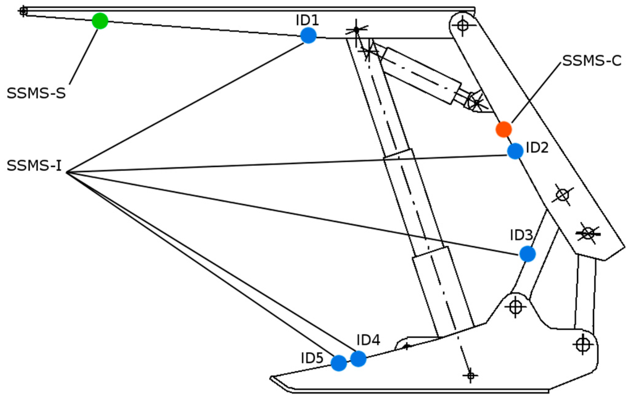
The SSMS (Shield Support Monitoring System) was designed to measure changes in the geometry of a powered roof support (
Figure 6).
The system consists of five SSMS-I inclinometers (ID1, ID2, ID3, ID4 and ID5), which were mounted on particular elements of the shield support section (
Figure 6):
- -
ID1 was mounted on the canopy and connected by cable to the tip to face the distance module SSMS-S and the Central Unit SSMS-C.
- -
ID2 was mounted on the goaf shield and connected by cable with the SSMS-C Central Unit and inclinometer ID3.
- -
ID3 was mounted on the lemniscate and connected to inclinometer ID2 and inclinometer ID4.
- -
ID4 and ID5 were mounted on a base of shield support and connected to each other and to inclinometer ID3.
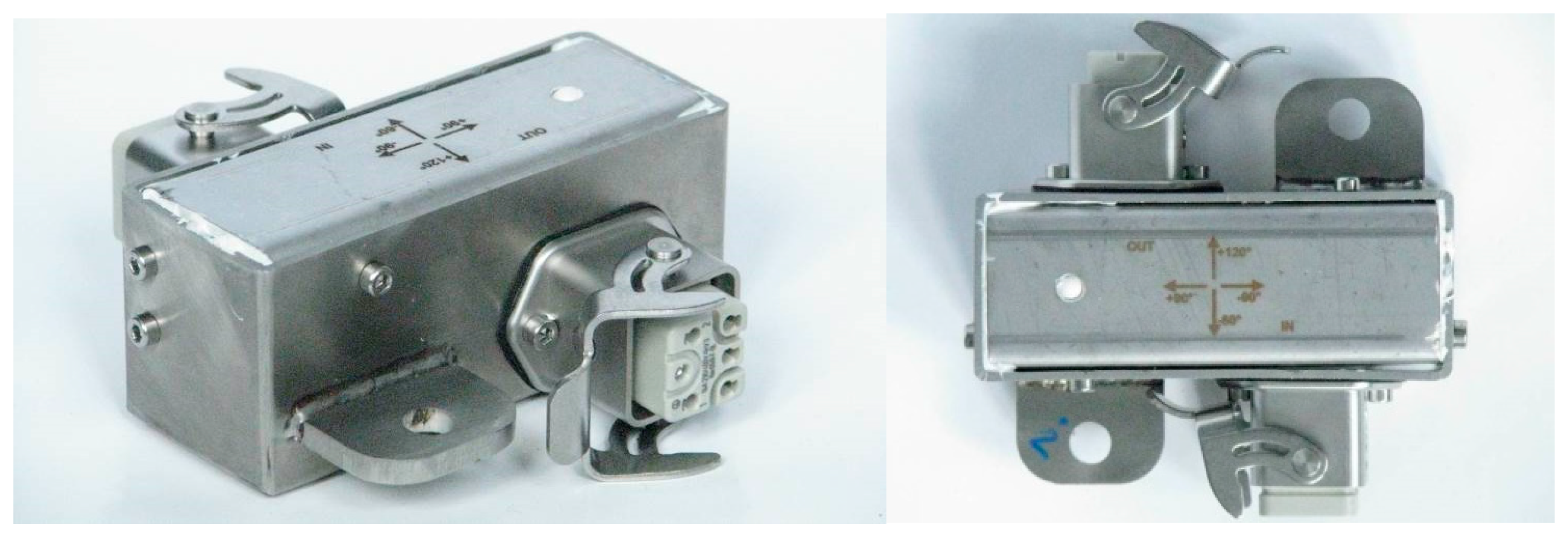
2.2. Inclinometer SSMS-I
The two-axis inclinometer SSMS-I is the basic component of the Shield Support Monitoring System (SSMS) (
Figure 7). The inclinometer complies with the 94/9/WE ATEX directive and harmonized standards [
22] and can be used in underground mining applications. The module is designed for continuous operation, regardless of the methane concentration, and is therefore designed as intrinsically safe. The inclinometer casing was made of stainless steel without lacquer coating. Each inclinometer was calibrated on a special rotary table. The use of the 180° rotary calibration method allows for the elimination of printed circuit board (PCB) assembly errors and casing manufacturing errors. After calibration, accuracies of 0.1° with a resolution of 0.01° were achieved.
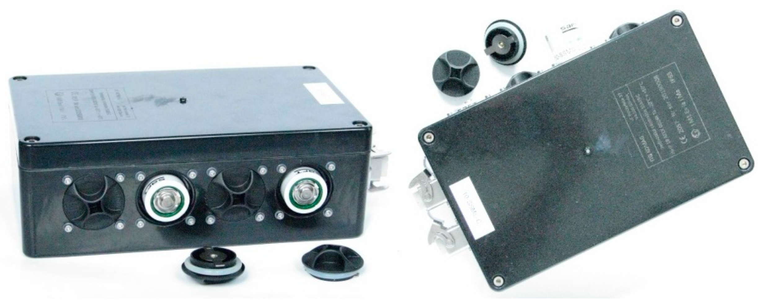
2.3. Central Unit SSMS-C
Data from each component of the system were read via a MODBUS RTU bus by the Central Unit SSMS-C (
Figure 8), which was mounted on the goaf shield. The unit is also the source of battery power for all inclinometers and is a network node of radio system topology, transmitting data from all shield supports located in the longwall panel. The module is designed for continuous operation, regardless of the methane concentration, and is therefore designed as intrinsically safe.
The main component of the SSMS-C circuit is the microcontroller unit. Its program contains the operating logic connecting all the components of the SSMS-C circuit:
A radio module for wireless communication;
A real-time clock circuit;
A communication circuit for connecting the SSMS-I sensors;
A power supply management circuit for the SSMS-I sensors.
2.4. Field Test of SSMS at JSW Budryk Mine
The full testing program was realized at Budryk Mine. The purpose of the tests was to confirm the proper operation of the SSMS through verification of the angle measurement of the shield support components by each SSMS-I inclinometer (
Figure 9).
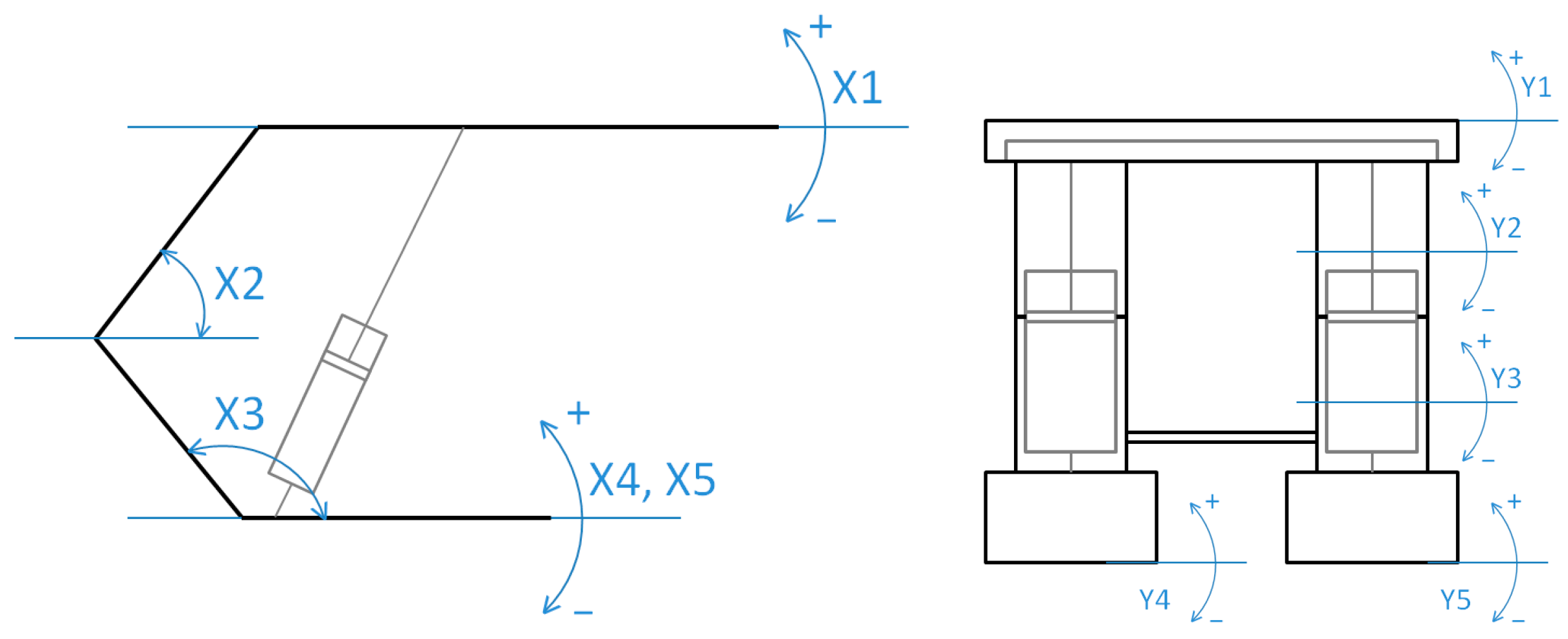
Figure 10 shows the angle symbols used during the tests, and
Figure 11 shows the taken measurements.
3. Measurement Accuracy
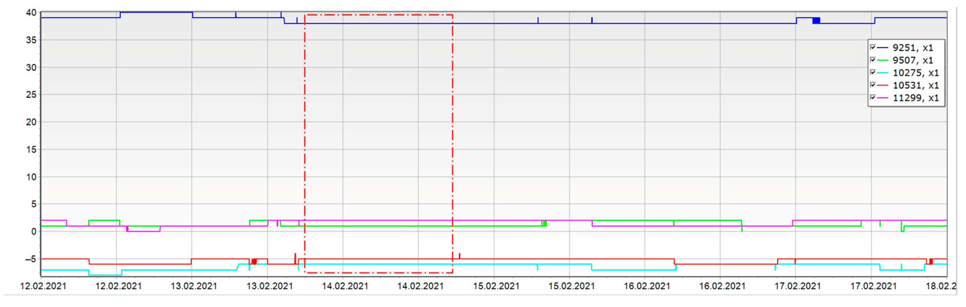
The tests yielded a substantial volume of monitoring data that demanded thorough analysis. Visualizing and analyzing the data proved time-consuming, necessitating specific data filtering and processing. To evaluate the collected measurements’ quality and assess the accuracy of the measuring equipment developed at KOMAG Institute, days without mining activity were chosen for additional statistical analyses. During these inactive periods, the hydraulic system pressure increased as a result of elevated rock mass pressure.
Analysis of the measurement results from tests of the inclinometers installed on powered roof supports from the days of longwall standstill allowed to verify their stability and behavior in static conditions. This was the basis for calibrating and verifying the measuring devices to ensure accurate and reliable results in the future.
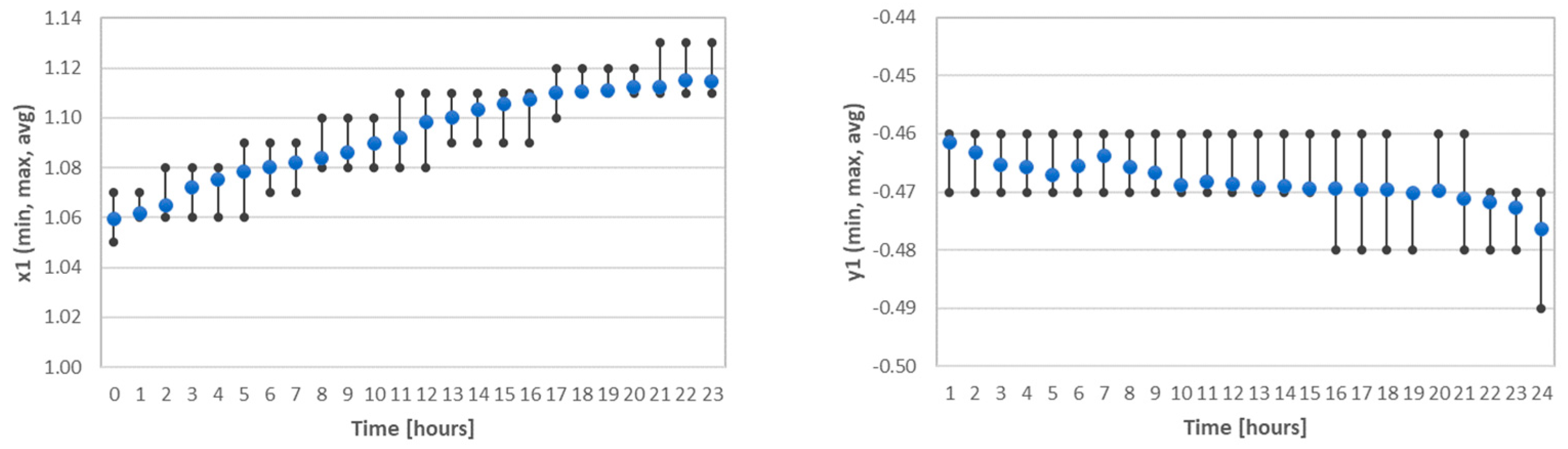
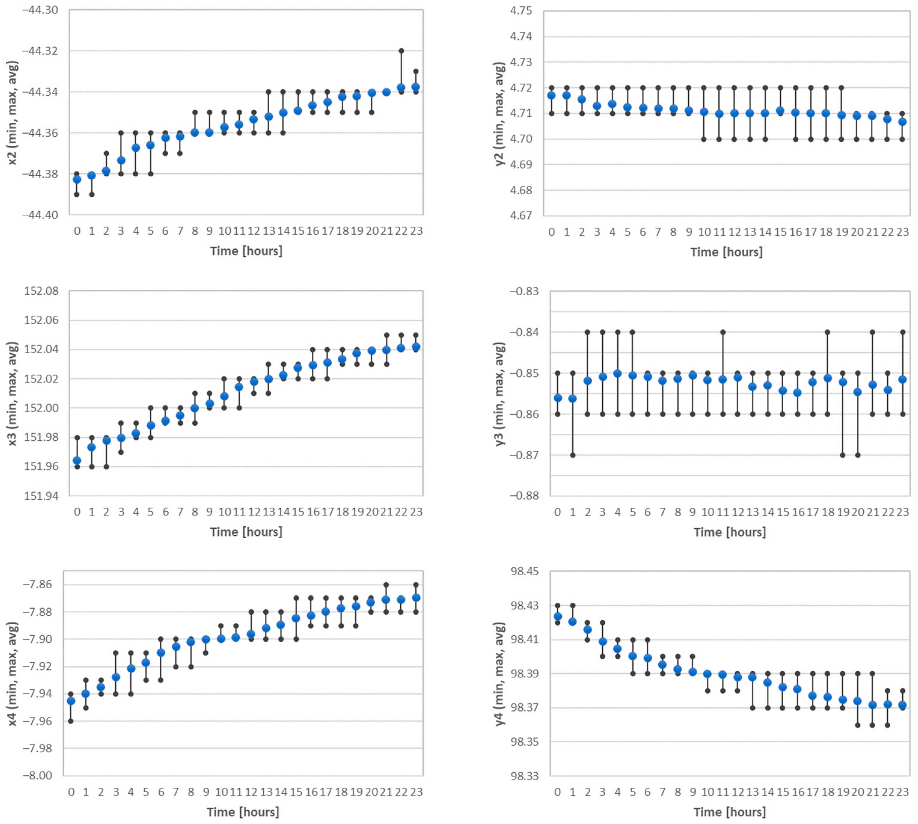
Central tendency measures, such as medians, and variability measures, including min and max values and quartiles, were calculated for each variable. The resulting values are depicted on the tables below. The tables illustrate the ranges of values for the selected variables, plotted separately for case groups categorized by shield support numbers. Median values for central tendency and scatter statistics (quartiles, min–max values) were calculated for each case group and are detailed in
Table 1,
Table 2,
Table 3,
Table 4 and
Table 5 and presented in
Figure 12.
Based on the calculations shown in
Table 1 and
Table 2, the data do not have a normal distribution. Tests for normal distribution (Kolmogorov–Smirnov test, Shapiro–Wilk test, D’Agostino–Pearson) were performed for the hypothesis that the distribution of the observations in the sample is normal (if
p < 0.05 then rejected normality). Values of excess kurtosis and skewness were other than zero.
The calculated standard deviation values were used to assess the precision of the measurements and the accuracy of the production processes of the designed devices. The in situ tests confirmed, as in the laboratory tests, that the accuracy of the inclinometers was higher than the assumed 0.5%. The results were analyzed every hour to detect unusual behavior of the inclinometers, which could result from technical problems or changes in the mine conditions, e.g., increasing pressure of the roof.
The test results therefore confirmed that the structure of the SSMS and the signal filtering algorithms used are correct and resistant to dynamic changes.
4. Conclusions
Designing electronic devices to comply with the ATEX directive is a complex and difficult process due to the strict regulations and rigorous standards for safety in explosive atmospheres such as underground coal mines.
The aim of the research presented in this paper was to verify the correctness of manufacture and measurement accuracy of designed devices complying with the above directive, which is a key process in terms of the effectiveness of these devices in potentially hazardous environments containing hazards associated with the presence of flammable gases and/or dust.
In coal mines, conditions can be constantly changing, including changes in moisture levels, pressure or temperature. The calculations performed (including standard deviation) allowed us to confirm the correct operation of the developed electronic devices under changing operating conditions. Repeatability was confirmed by the measurement results being close to each other (low standard deviation) and showing little variability (low standard deviation and skewness close to zero). Analysis of the quartiles could help identify possible deviations or anomalies in the data.
The tests aimed to evaluate both the correctness and accuracy of the measurement apparatus and the impact of operating conditions on the system’s usability, specifically focusing on existing roof supports.
Handling the extensive data gathered for analysis posed a significant challenge. The process of data visualization and analysis was time-consuming, requiring special attention to data filtering and processing. To assess the quality of the collected measurements and analyze the accuracy of the measuring equipment developed at KOMAG, a statistical analysis was conducted on data from days without mining activities and periods when the hydraulic system pressure increased solely due to rock mass pressure. The presented data affirm minimal scattering and the sensors’ high accuracy.
The accuracy of the measuring system was analyzed to determine its suitability in the process of analyzing changes in roof support geometry over longer time—e.g., more than 5 h of operation of a longwall complex. Operational experience indicates that the biggest error in the process of mapping the section geometry is due to the installation method of inclinometers. The manufacturing tolerance of the powered roof support components and the accuracy of the mounting brackets make it difficult to map the geometry accurately. It has been suggested that interaction of the roof support with the rock mass affects analysis rather than the geometry itself. Roof overhanging in a collapse zone can be an example. This will cause uplift of the front part of the canopy and can be detected by the change in angle over time rather than its actual value. In order to make accurate predictions of the phenomena in the longwall panel, it was necessary to confirm that the measuring system has a high accuracy in real conditions, as demonstrated in the test. The developed measuring system must be equipped with algorithms that monitor the interaction between the roof support and the rock mass. It is recommended that the change in angle over time be used in the data analysis process. Mapping the geometry of the roof support is possible but will be subject to the error associated with the installation of inclinometers.
Measurement data were not available at all times (due to cabling failure and radio transmission errors). It is necessary to eliminate cable connections (all system components should send measurement data wirelessly) and, consequently, to develop an algorithm to manage data transmission in a network with a mesh topology. Research in this area is already underway.
Additional inspiration for future research directions can be found in [
23,
24,
25,
26,
27,
28].
Author Contributions
Conceptualization, D.J., M.S., J.J. (Jerzy Jagoda), J.J. (Jerzy Jura), M.H. and J.R.-R.; methodology, D.J., M.S., J.J. (Jerzy Jagoda), J.J. (Jerzy Jura) and J.R.-R.; software, M.S., J.J. (Jerzy Jagoda), J.J. (Jerzy Jura) and J.R.-R.; validation, D.J., M.S., J.J. (Jerzy Jagoda), J.J. (Jerzy Jura), M.H. and J.R.-R.; formal analysis, D.J., M.S., J.J. (Jerzy Jagoda), J.J. (Jerzy Jura) and J.R.-R.; investigation, D.J., M.S., J.J. (Jerzy Jagoda), J.J. (Jerzy Jura) and J.R.-R.; resources, D.J., M.S., J.J. (Jerzy Jagoda), J.J. (Jerzy Jura) and J.R.-R.; data curation, D.J., M.S., J.J. (Jerzy Jagoda), J.J. (Jerzy Jura), M.H. and J.R.-R.; writing—original draft preparation, D.J., M.S., J.J. (Jerzy Jagoda), J.J. (Jerzy Jura) and J.R.-R.; writing—review and editing, D.J., M.S., J.J. (Jerzy Jagoda), J.J. (Jerzy Jura) and J.R.-R.; visualization, D.J., M.S., J.J. (Jerzy Jagoda), J.J. (Jerzy Jura) and J.R.-R.; supervision, D.J., M.S., J.J. (Jerzy Jagoda), J.J. (Jerzy Jura) and J.R.-R.; project administration, D.J., M.S., J.J. (Jerzy Jagoda), J.J. (Jerzy Jura) and J.R.-R. All authors have read and agreed to the published version of the manuscript.
Funding
The research work undertaken in PRASS III (Productivity and safety of shield support, grant 752504 (2017)) was supported by the EU Research Fund for Coal and Steel (RFCS) as well as the Ministry of Science and Higher Education.
Institutional Review Board Statement
Not applicable.
Informed Consent Statement
Not applicable.
Data Availability Statement
Data are contained within the article.
Conflicts of Interest
The authors declare no conflict of interest.
References
- Wojtaszczyk, M. 25 years of accreditation of the Testing Laboratory at KOMAG Institute of Mining Technology. Min. Mach. 2020, 164, 58–66. [Google Scholar] [CrossRef]
- Masny, W. Powered Support in Dynamic Load Conditions—Numerical Analysis. Arch. Min. Sci. 2020, 65, 453–468. [Google Scholar] [CrossRef]
- Lubosik, Z.; Rajwa, S.; Walentek, A.; Masny, W.; Wrana, A. The role of powered support in ensuring the proper longwall working cross-section area in rockburst-prone seams. In Proceedings of the 9th International Symposium on Occupational Health and Safety (SESAM 2019), Hunedoara, Romania, 3 October 2019. [Google Scholar] [CrossRef]
- Prusek, S.; Rajwa, S.; Wrana, A.; Krzemień, A. Assessment of roof fall risk in longwall coal mines. Int. J. Min. Reclam. Environ. 2017, 31, 558–574. [Google Scholar] [CrossRef]
- Langosch, U.; Ruppel, U.; Wyink, U. Longwall roof control by calculation of the shield support requirements. In 2003 Coal Operators’ Conference; University of Wollongong: Wollongong, NSW, Australia, 2003; pp. 162–172. [Google Scholar]
- EN 1804-1:2004; Machines for Underground Mines—Safety Requirements for Hydraulic Powered Roofsupports—Part 1: Support Units and General Requirements. European Committee for Standardization: Brussels, Belgium, 2004.
- Herezy, Ł.; Janik, D.; Skrzypkowski, K. Powered Roof Support—Rock Strata Interactions on the Example of an Automated Coal Plough System. Stud. Geotech. Mech. 2018, 40, 46–55. [Google Scholar] [CrossRef]
- Cheng, J.; Wan, Z.; Ji, Y. Shield-Roof Interaction in Longwall Panels: Insights from Field Data and Their Application to Ground Control. Adv. Civ. Eng. 2018, 2018, 3031714. [Google Scholar] [CrossRef]
- Sreenivasa, R.; Debasis, D.; Hemant, K. Numerical analysis of a longwall mining cycle and development of a composite longwall index. J. Rock Mech. Min. Sci. 2016, 89, 43–54. [Google Scholar]
- Jiang, B.; Xin, Z.; Zhang, X.; Deng, Y.; Wang, M.; Li, S.; Ren, W. Mechanical properties and influence mechanism of confined concrete arches in high-stress tunnels. Int. J. Min. Sci. Technol. 2023, 33, 829–841. [Google Scholar] [CrossRef]
- Song, G.; Chugh, Y.P.; Wang, J. A numerical modelling study of longwall face stability in mining thick coal seams in China. Int. J. Min. Miner. Eng. 2017, 8, 35. [Google Scholar] [CrossRef]
- Yang, J.X.; Liu, C.; Yu, B. The interaction between face support and surrounding rock and its rib weakening mechanism in hard coal seam. Acta Montan. Slovaca 2017, 22, 67–78. [Google Scholar]
- Rajwa, S.; Janoszek, T.; Prusek, S. Influence of canopy ratio of powered roof support on longwall working stability—A case study. Int. J. Min. Sci. Technol. 2019, 29, 591–598. [Google Scholar] [CrossRef]
- Wang, P.; Zhao, J.; Feng Wang, Z. Interaction between vertical stress distribution within the goaf and surrounding rock mass in longwall panel systems. J. South. Afr. Inst. Min. Metall. 2018, 118, 745. [Google Scholar] [CrossRef]
- Zhao, J.; Wang, P.; Su, Y. An Innovative Longwall Mining Technology in Tangshan Coal Mine, China. Minerals 2017, 7, 14. [Google Scholar] [CrossRef]
- Wang, P.; Zhao, J.; Chugh, Y.P.; Wang, Z. A Novel Longwall Mining Layout Approach for Extraction of Deep Coal Deposits. Minerals 2017, 7, 60. [Google Scholar] [CrossRef]
- Tokarczyk, J.; Dudek, M. Methods for Computer Aiding the Configuration and Assessment of Auxiliary Mine Transportation Means. Manag. Syst. Prod. Eng. 2020, 28, 268–275. [Google Scholar] [CrossRef]
- Guo, J.; Feng, G.; Wang, P.; Qi, T.; Zhang, X.; Yan, Y. Roof Strata Behavior and Support Resistance Determination for Ultra-Thick Longwall Top Coal Caving Panel: A Case Study of the Tashan Coal Mine. Energies 2018, 11, 1041. [Google Scholar] [CrossRef]
- Thomas, M. Barczak: Examination of Design and Operation Practices for Longwall Shields; Książki Google; US Department of the Interior, Bureau of Mines: Washington, DC, USA, 1992.
- Stankiewicz, K. Smart mining communication systems. J. Mach. Constr. Maint. Probl. Eksploat. Rocz. 2019, 2, 105–111. [Google Scholar] [CrossRef]
- Huang, R.; Ma, L.; Zhai, G.; He, J.; Chu, X.; Yan, H. Resilient Routing Mechanism for Wireless Sensor Networks with Deep Learning Link Reliability Prediction. IEEE Access 2020, 8, 64857–64872. [Google Scholar] [CrossRef]
- Figiel, A. Technical safety of machinery and equipment in the aspect of the activities of the KOMAG Division of Attestation Tests, Certifying Body. Min. Mach. 2020, 1, 2–8. [Google Scholar] [CrossRef]
- Zhu, C.; He, M.C.; Jiang, B.; Qin, X.Z.; Yin, Q.; Zhou, Y. Numerical investigation on the fatigue failure characteristics of water-bearing sandstone under cyclic loading. J. Mt. Sci. 2021, 18, 3348–3365. [Google Scholar] [CrossRef]
- Szurgacz, D.; Brodny, J. Tests of Geometry of the Powered Roof Support Section. Energies 2019, 12, 3945. [Google Scholar] [CrossRef]
- Rajwa, S. The Influence of the Geometrical Construction of the Powered Roof Support on the Loss of a Longwall Working Stability Based on the Practical Experience. Arch. Min. Sci. 2020, 65, 511–529. [Google Scholar]
- PRASS III Website. Available online: http://prass3.komag.eu (accessed on 20 September 2021).
- Stankiewicz, K.; Jagoda, J.; Tonkins, M. Intelligent algorithms for routing sensory networks operating in explosion hazard zones. Min. Sci. 2021, 28, 103–115. [Google Scholar] [CrossRef]
- Woszczyński, M.; Rogala-Rojek, J.; Stankiewicz, K. Advancement of the Monitoring System for Arch Support Geometry and Loads. Energies 2022, 15, 2222. [Google Scholar] [CrossRef]
| Disclaimer/Publisher’s Note: The statements, opinions and data contained in all publications are solely those of the individual author(s) and contributor(s) and not of MDPI and/or the editor(s). MDPI and/or the editor(s) disclaim responsibility for any injury to people or property resulting from any ideas, methods, instructions or products referred to in the content. |
© 2023 by the authors. Licensee MDPI, Basel, Switzerland. This article is an open access article distributed under the terms and conditions of the Creative Commons Attribution (CC BY) license (https://creativecommons.org/licenses/by/4.0/).


 ,
, 


