Article

Effects of Different Channel Geometries of Metallic Bipolar Plates on Proton Exchange Membrane Fuel Cell Performance

Eurecat, Centre Tecnològic de Catalunya, Product Innovation & Multiphysics Simulation Unit, Av. Universitat Autònoma, 23, 08290 Cerdanyola del Vallès, Spain
*
Author to whom correspondence should be addressed.
Energies 2023, 16(23), 7702; https://doi.org/10.3390/en16237702
Submission received: 26 September 2023 / Revised: 15 November 2023 / Accepted: 20 November 2023 / Published: 22 November 2023
(This article belongs to the Topic Hydrogen Energy Technologies, 2nd Edition)

Abstract

:
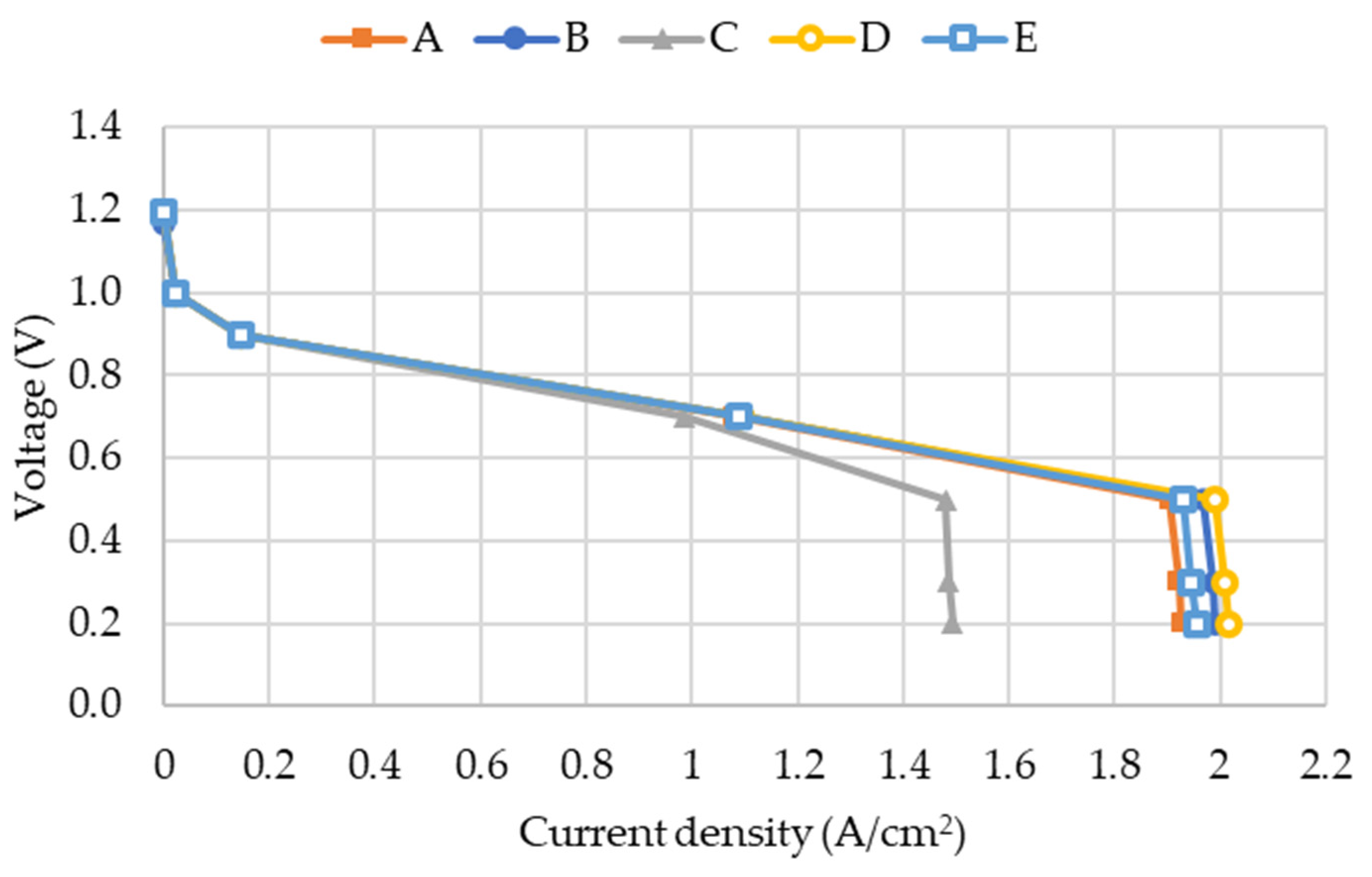
This paper investigates the effects of different channel geometries on the performance of Proton Exchange Membrane Fuel Cells (PEMFCs). The study employs computational fluid dynamics (CFD) coupled with thermal and electrochemical simulations to analyze five channel geometries (cases A to E) of bipolar plates. A thorough study on this topic is not found in the literature and aims to identify designs that optimize performance and align with cost-effective production methods. Among the various studied geometries, case D, featuring a trapezoidal cross-section, exhibited the most favorable performance compared to the others, with a current density value of 2.01 A/cm2 and a maximum temperature of 74.89 °C at 0.3 V, leading to an increase in generated power of 4.46%, compared to base case A. The trapezoidal shape enhanced the contact area with the reacting region, resulting in higher reaction rates and an improved overall performance. However, the study also highlights the relevance of velocity and turbulence, with case B demonstrating an enhanced performance due to its higher velocity, and case E benefiting from localized higher velocity regions and turbulence created by baffles. Case B can increase generated power at its peak by around 3.21%, and case E can improve it by 1.29%, with respect to case A. These findings underscore that contact area has a major impact on the PEMFC performance, but velocity and turbulence also play relevant roles. Additionally, trapezoidal channels can be easily manufactured through sheet metal-forming techniques, aligning well with new market trends of weight and cost reduction on bipolar plates. Fuel and oxygen utilization percentages, 38.14% and 62.96% at 0.3 V, respectively, further confirm the superiority of trapezoidal channels, providing insights into optimizing the PEMFC performance. This exhaustive study contributes valuable information for designing efficient metallic bipolar plates and advancing the development of practical fuel cell technologies.

1. Introduction

Proton Exchange Membrane (PEM) fuel cells have emerged as promising alternative energy sources due to their high efficiency, low emissions, and wide range of applications [1,2].
PEMFCs offer significant advantages over thermal energy storage (TES) systems in renewable and alternative energy applications. While both have the capacity of bridging the gap between energy supply and demand [3,4,5], the electrochemical operation of PEMFCs ensures efficient energy conversion, and their quick response to demand changes makes them well-suited for grid stabilization and the accommodation of intermittent renewable energy sources. Moreover, PEMFCs boast a long operational life and a smaller physical footprint, enhancing their cost-effectiveness and versatility [6].
The performance and cost-effectiveness of PEM fuel cells depend on various factors, including the choice of bipolar plate materials and the design of flow channels [7].
The importance of bipolar plates in PEM fuel cells cannot be overstated, as they play a crucial role in facilitating efficient reactant distribution, enhancing mass transfer, and reducing pressure drop. Therefore, the selection of low-cost bipolar plate materials that exhibit a high fuel cell performance is vital for the widespread adoption of PEM fuel cells in the competitive world market [8].
Research on the channel distribution of bipolar plates has been conducted to optimize fuel cell designs and reduce the pressure drop. This involves studying the arrangement and layout of channels within the bipolar plate to ensure the efficient distribution of reactants and the minimization of flow resistance.
Several studies have extensively investigated the impact of different flow field configurations on fuel cell performance, with a focus on Proton Exchange Membrane Fuel Cells (PEMFCs). Hazar et al. [9] delved into this topic by studying five alternative flow fields and comparing them to the commonly used serpentine flow field. Their study conclusion highlighted the superiority of the “Parallel M-type” flow field, which exhibited the highest power density, outperforming the serpentine flow field. This performance advantage was attributed to its lower pressure drop, higher current density, and increased reactant activity.
With the objective to reduce pressure drop, Wilberforce et al. [10] explored common fuel cell flow plate designs. The study showcased that adopting modifications inspired by a diesel injection system approach could effectively reduce pressure drop, thereby potentially enhancing cell performance. However, the researchers emphasized the need to consider other factors, as pressure drop reduction alone might not guarantee the overall improvement in fuel cell performance.
Chen et al. [11] presented a 3D multi-physics coupled model for PEMFCs with serpentine and parallel flow fields, which was validated with experimental data. The study explored the performance of PEMFCs with compensation flow fields. By comparing the performance of PEMFCs with parallel and parallel-serpentine-parallel flow channels, the results indicated that the latter configuration offers superior oxygen distribution and electrochemical performance. Therefore, compensation flow fields show promise as a viable choice for enhancing PEMFCs stack development in the near future.
In their study, Arif et al. [12] conducted the simulations of four different flow channel designs: single-channel serpentine, two-channel serpentine, three-channel serpentine, and parallel channel with headers. The findings revealed that the three-channel serpentine configuration outperformed the others due to its uniform gas distribution over the catalyst layer and lower pressure drop compared to other serpentine channels.
Carcadea et al. [13] utilized numerical analysis to investigate various flow field designs in a large active area PEMFC. Among the three types of multiple-serpentine channels evaluated, the 14-channel serpentine design demonstrated the best performance, especially at high current densities. Experimental testing further confirmed the modeling results, revealing that varying channel width and depth significantly influenced fuel cell performance. The study highlighted that the 14-channel serpentine design, along with smaller channel depths, led to an increase in the maximum current density due to improved water removal and membrane humidification.
Similarly, Limjeerajarus and Charoen-Amornkitt [14] conducted a study that focused on the impact of flow field design on a 5 cm2 PEMFC, comparing six different flow field designs, with a particular emphasis on parallel in series flow fields. The research results suggested that for small-sized PEMFCs, flow fields with fewer channels offered better uniformity and cell performance. Additionally, the influence of geometric configuration became more pronounced with an increasing number of channels.
While there has been extensive research conducted on the channel distribution of bipolar plates, insufficient attention has been given to the exploration of channel shape and cross-section itself.
Al-Okbi et al. [15] conducted a comparative study focusing on square and triangular cross-section channels. Their research revealed that triangular channels exhibited a better PEMFC performance when compared to square channels. One of the key factors contributing to this improved performance was the regular velocity distribution at the entrance and exit of the triangular flow path.
Building upon the idea of optimizing flow channels, Xu et al. [16] examined the influence of wave-shaped flow channels and grooves within the gas diffusion layer (GDL). The introduction of grooves in the GDL was found to enhance mass transfer, resulting in an increased net power density. The researchers identified the optimal flow channel design, comprising nine wavy cycles and grooves, which led to a substantial improvement in net power density.
Xu et al. [17] explored the impact of trapezoidal channels and baffles on the net power density of Proton Exchange Membrane Fuel Cells. They concluded that optimizing the design to change the effective contact surface between the flow channel and the gas diffusion layer significantly improves a fuel cell’s current density. Results demonstrated that trapezoidal cross-sectional flow channels with baffles outperformed the basic straight channels, showing higher efficiency and overall performance.
Inspired by small intestinal villi, Xuan et al. [18] introduced a novel three-dimensional (3D) bionic cathode flow field for Proton Exchange Membrane Fuel Cells (PEMFCs). Simulation results showed that the proposed 3D bionic flow field significantly improved gas supply and water removal in the cathode, enhanced gas mass transfer by increasing contact areas with the gas diffusion layer, and lead to a more uniform distribution of currents in the membrane.
Overall, these studies collectively reinforce the importance of channel shape optimization in PEM fuel cell design to contribute to the development of more efficient and high-performance fuel cell systems.
Furthermore, the formability of metallic bipolar plates through stamping processes has also been a subject of research interest. Stamping is a common manufacturing technique that can be used to shape bipolar plates that offers several advantages, including high precision, complex geometries, efficient reactant distribution, cost-effectiveness, and durability, making them a favorable choice for fuel cell applications.
In a study by Neto et al. [19], the formability of metallic bipolar plates for PEM fuel cells was numerically investigated. Their study explored the influence of channel shape on the manufacturability and performance of the bipolar plates. Wilberforce et al. [20] studied the effect of different bipolar plate materials such as Aluminum (Al), Copper (Cu), and Stainless Steel (SS) on a single stack of PEM fuel cells both numerically and experimentally. The results show that Al serpentine bipolar plate material performed better than Cu and SS materials.
Despite the advancements in fuel cell modeling [21], there is still not enough research on channel geometries that are compatible with forming manufacturing processes while enhancing fuel cell performance. This study aims to address this gap by coupling computational fluid dynamics (CFD) with thermal and electrochemical simulations. The novelty of this study lies in the absence of a comparable exhaustive analysis within the existing literature. By analyzing the effects of different flow field shapes, thicknesses, and cross-sections of the flow channels, insights were gained into how these factors influence fuel cell performance and the parameters with a higher impact. The goal is to identify optimal channel geometries that not only improve performance but also align with the requirements of sheet metal-forming processes for efficient and cost-effective production of fuel cell bipolar plates.

2. Methodology

2.1. Analyzed Cases

Reactivity of the fuel cell is based on the ability of hydrogen to diffuse towards the membrane; thus, this implies that increasing the contact area between the channel and the GDL will improve performance [15,17,18]. Another parameter that seems to have an influence on the fuel cell performance is velocity, or in other words, the generation of turbulence to improve diffusivity [6,16,17].
To evaluate the effects of these parameters and their impact on performance, five different geometries are simulated. Figure 1 shows channel cross-section for all geometries, where the channel is depicted in cyan, and the bipolar plate is shown in gray. MEA is located on the top of the drawing, and a symmetric geometry is placed next to it, being the same for anode and cathode channels (as shown in Figure 2).
Proposal A corresponds to a typical design channel with a rectangular cross-section, which acts as a reference. To include the effects of channel thickness and width, geometries B and C are generated as variations of a rectangular cross-section. Both allow the increase in velocity, as indicated by Table 1. Proposal D has the same cross-sectional area as the reference geometry but with a trapezoidal shape, thus increasing the contact area with the MEA. Finally, proposal E (longitudinal cross-section) has the same cross-sectional area as case A but introduces baffles within the channel to locally increase velocity and increase turbulence in those areas.
The analysis of these five cases will allow the determination of the effects and impact of contact area, velocity, and turbulence on the PEMFC performance.

2.2. Geometry

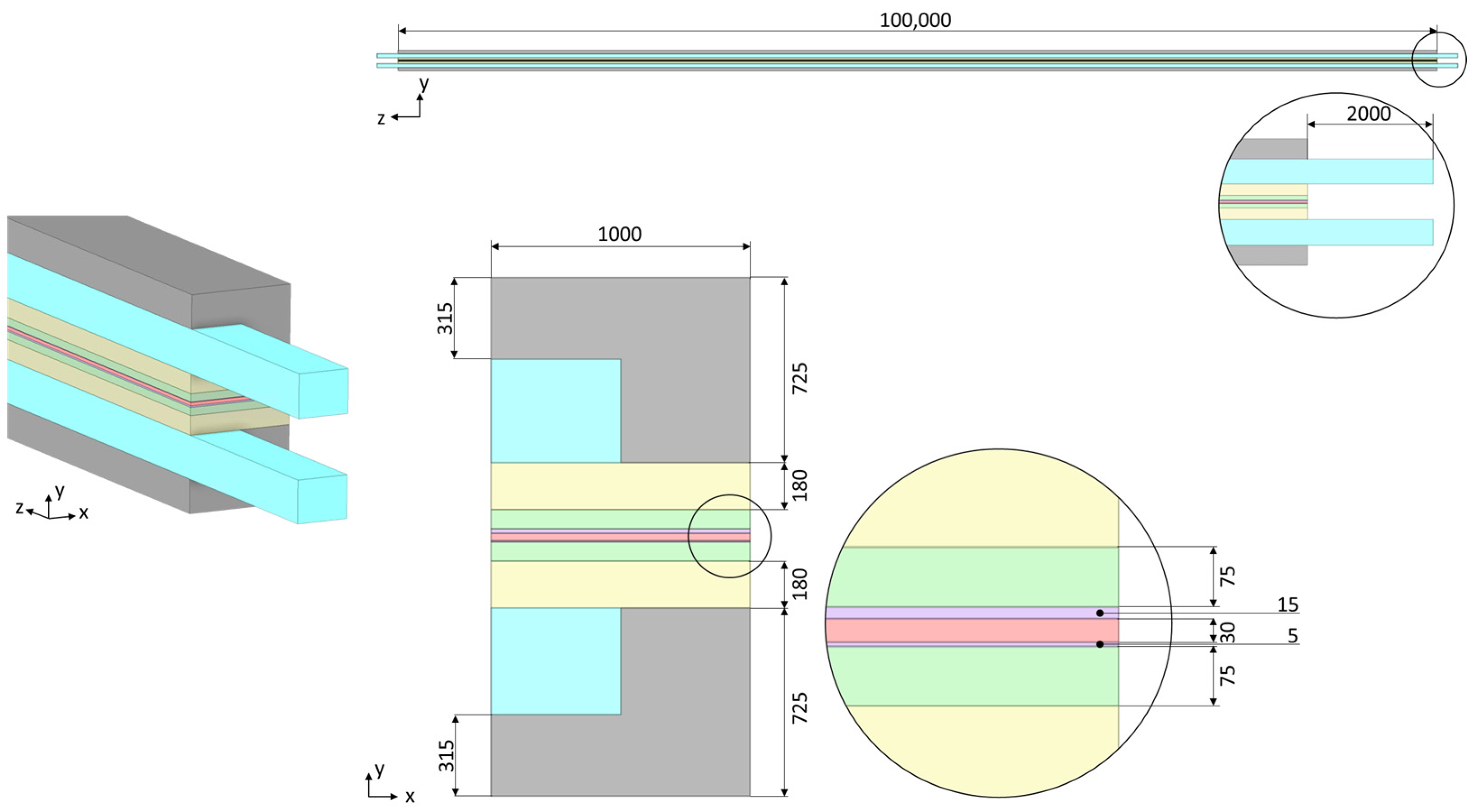
Simulated 3D base geometry is depicted in Figure 2, where all parts are drawn with Ansys SpaceClaim. General dimensions are maintained for all 5 simulated geometries and only the channel shape is modified according to Figure 1.
Using the same criteria as before, gray parts correspond to the bipolar plates, gas channels are defined in cyan, gas diffusion layers (GDL) are shown in yellow, micro-porous layers (MPL) are shown in green, catalyst layers are represented in purple, and finally, the membrane is presented in light red. With the current view, the anode side would be located on the top part and the cathode side would be at the lower part of the assembly.

2.3. Mesh

The corresponding 3D geometries are transferred to Ansys Workbench mesher to discretize the geometry into small computational elements. Due to the physical and chemical processes occurring within the MEA, the simulation of PEM fuel cells demands a fine and detailed mesh [12,22]. It is important to emphasize that the system exhibits high aspect ratios due to significant length scale disparities, ranging from 5–15 µm within the catalyst layers to 10 cm along the channel length, and thus, the implementation of a hexahedral mesh proves to be the most pragmatic choice under these circumstances [23]. Also, a gradual expansion of the mesh from the catalytic layers into the micro-porous layers (MPL) and into the gas-diffusion layers (GDL) is set, to avoid any sudden step changes that would compromise convergence [24].
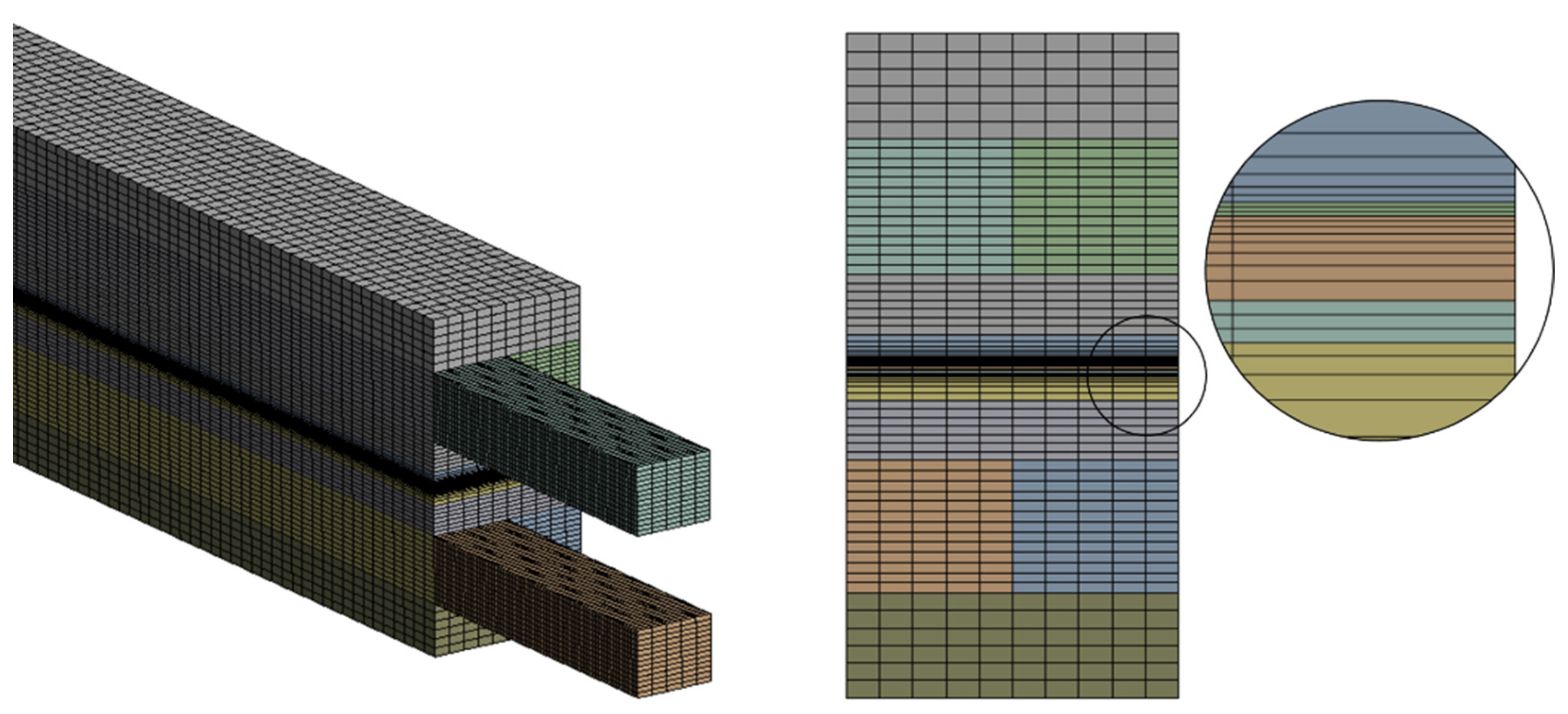
Following Ansys recommendations, 3 layers of cells are placed across the catalysts and 8 on the membrane. MPL and GDL mesh structure is adapted to progressively expand, maintaining the same element size at 100 µm. Anode and cathode channels are meshed in a similar way, having a total of 13 layers on the y-direction.
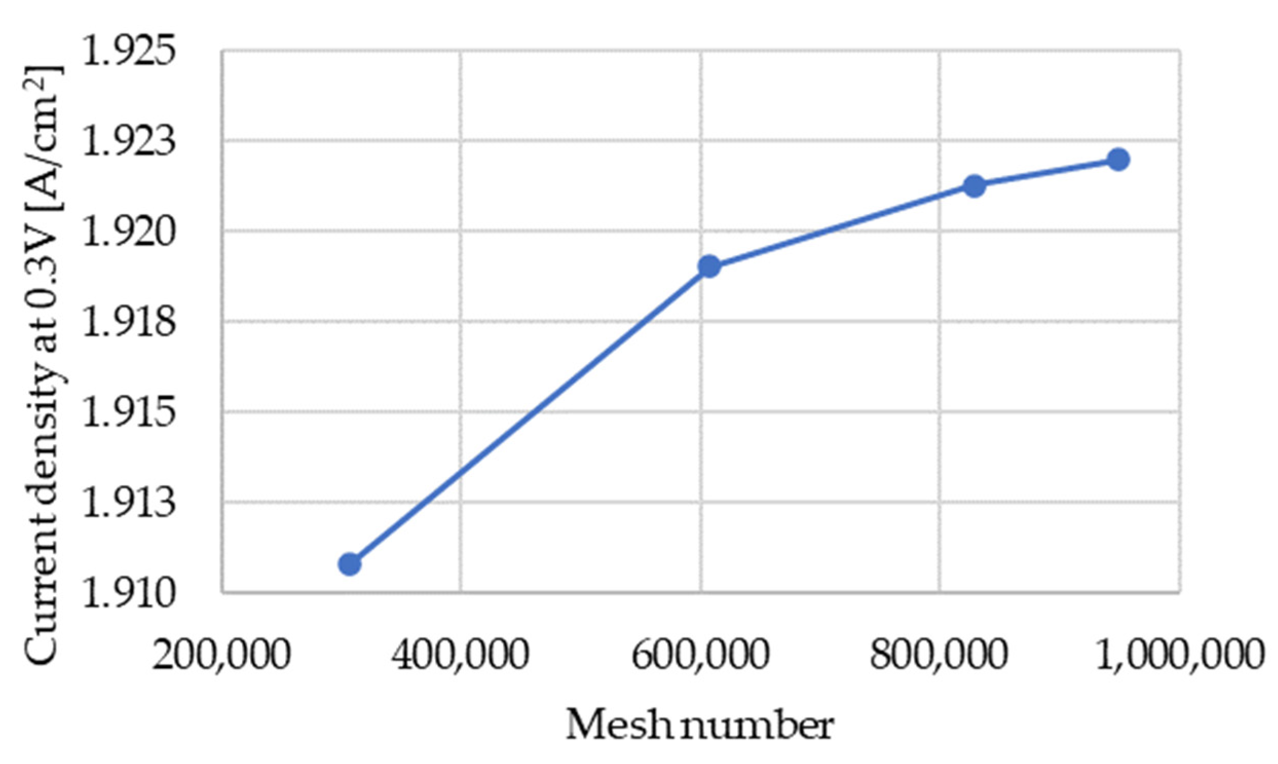
To evaluate mesh independence, four different meshes were examined, each with varying numbers of hexahedral elements: 306,456, 607,920, 828,090, and 948,090, as shown in Figure 3. The relative error in current density for grids containing 828,090 and 948,090 elements is calculated to be approximately 0.04% when operating at a voltage of 0.3 V. As a result, it is concluded that a mesh with 828,090 elements is adequately suitable for further computations [16].
Figure 4 shows the mesh details of case A. Remaining cases are meshed using the same criteria.

2.4. Model Assumptions and Governing Equations

For the generation of power via a PEMFC, hydrogen is supplied at the anode, and air is supplied at the cathode. Thus, these electrochemical reactions take place at the electrodes [1]:
H 2 2 H + + 2 e                         ( a n o d e )
1 2 O 2 + 2 e + 2 H + H 2 O                         ( c a t h o d e )
Electrons generated at the anode move through an external circuit to the cathode, while protons circulate through the membrane. Parallelly, water is generated at the cathode, both due to osmotic drag and electrochemical reactions, and when water vapor pressure exceeds saturation pressure, liquid water is formed [11,22].
To model the different multiphysical phenomena involved, ANSYS Fluent software with the PEM Fuel Cell Module addon-on, with capabilities of modeling electrochemistry, ionic and protonic charge transport, species gas transport, and generation and transport of liquid water and energy, is used to model the performance of the fuel cell with different channel geometries.
Key assumptions made for the model are as follows [11,25]:
  • Fluid flows are considered to be laminar, as Reynolds number for anode channels is below 35 and for cathode channels is below 255.
  • The operation of the PEM fuel cell is under non-isothermal and steady-state conditions.
  • Ideal gas laws are followed by all gas species.
  • MEA materials are assumed to be isotropic.
  • Transport and formation of liquid water are included.
Main governing equations for the modeling of PEMFCs is based on the conservation of mass, momentum, species transport, charge, and energy [24]. These equations are discussed briefly in this section and a more detailed description can be found on the Ansys PEM Fuel Cell Module manual [24].
Mass conservation:
· ( ρ u ) = S m
S m is a source term and varies according to Equations (4)–(6). At the anode, hydrogen is consumed to be transported to the cathode, and thus, source term (4) is applied. At the cathode, oxygen is consumed at source rate (5), and due to oxygen reduction reaction, the formation of liquid water occurs at the cathode at a rate according to (6).
S H 2 = M w , H 2 2 F R a n < 0
S O 2 = M w , O 2 4 F R c a t < 0
S H 2 O = M w , H 2 O 2 F R c a t > 0
Momentum conservation:
· ( ρ   u   u i ) = · ( μ u i ) p i + S m o m , i                                         i = x ,   y , z
where S m o m , i is a source term that has the following equation for catalyst layers and GDL regions.
S m o m , i = μ K i g u i
Charge conservation:
Electronic and protonic potentials are solved using conservation of charge equations.
· ( σ s o l ϕ s o l ) + R s o l = 0
· ( σ m e m ϕ m e m ) + R m e m = 0
where R s o l equals R a n at the anode side and + R c a t at the cathode side, and R m e m equals + R a n at the anode side and R c a t at the cathode side.
Source terms ( R ) of Equations (9) and (10) are modelled using the Butler–Volmer equations given in (11) and (12).
R a n = ( ζ a n j a n r e f ) ( [ H 2 ] [ H 2 ] r e f ) γ a n ( e α a n F η a t R T e α c a t F η a n R T )
R c a t = ( ζ c a t j c a t r e f ) ( [ O 2 ] [ O 2 ] r e f ) γ c a t ( e α a n F η c a t R T + e α c a t F η c a t R T )
Most variables such as reference exchange current density per active surface area (jref), specific active surface area (ζ), and charge transfer coefficients (α) are input parameters and are detailed in Table 2. Parallelly, [H2], [O2], [H2]ref, and [O2]ref refer to the concentration of species in anode and cathode reactions.
Energy conservation:
The variation in the temperature balances and conserves the energy within the PEMFC [26].
· ( ρ c T u T ) = · ( k T e f f T ) + S h
where S h represent the additional volumetric sources added to the thermal energy equation as not all chemical energy released in the electrochemical reactions can be converted to electrical work due to irreversibilities of the processes [24].
Sh = hreactRan,catμan,cat + I2Rohm + hL

2.5. Model Validation

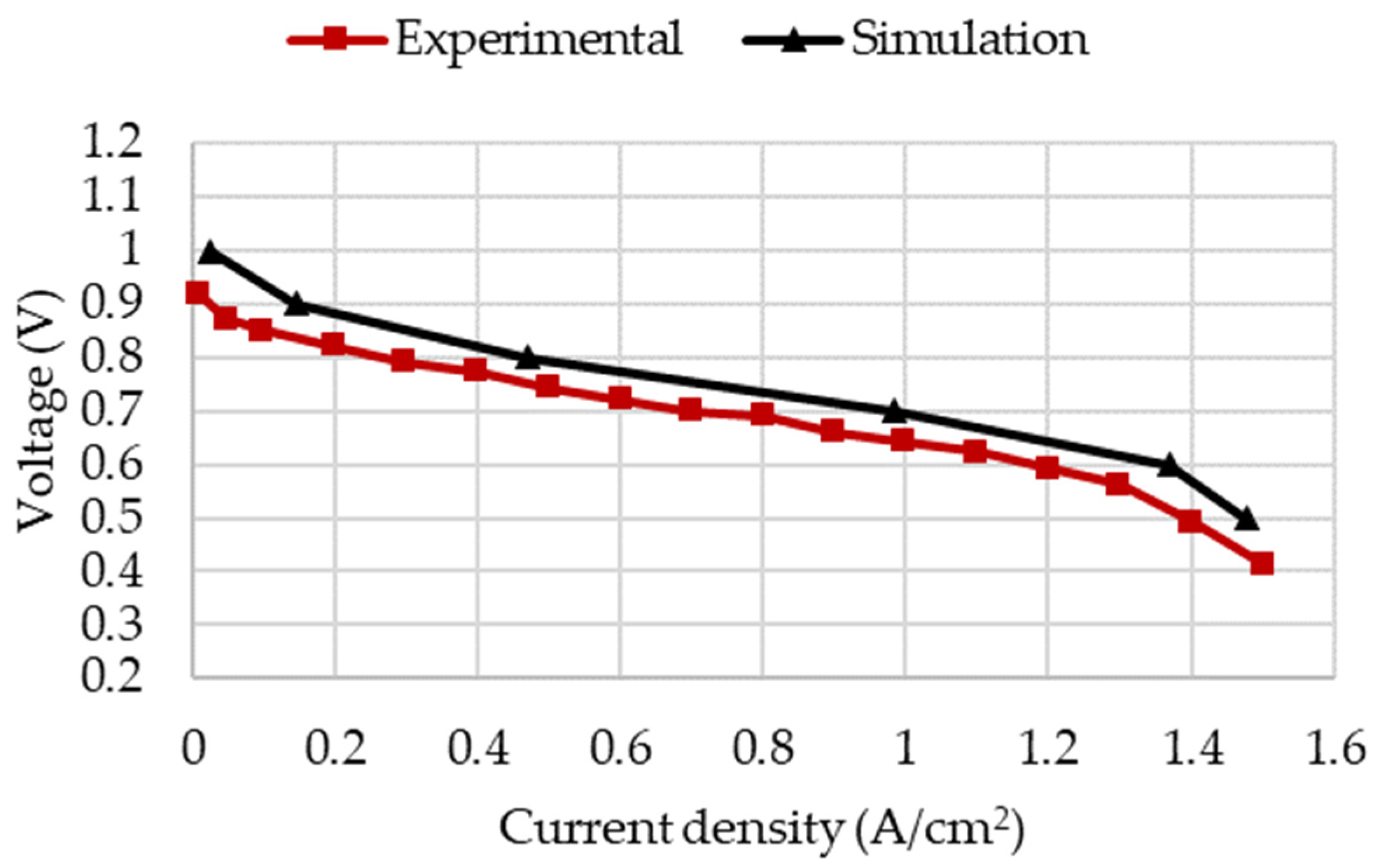
To validate the accuracy of the numerical model, this study compares the simulated fuel cell polarization curve with the experimental data from Al-Baghdadi et al. [27]. As illustrated in Figure 5, there is a close agreement between the simulation and experimental results. Consequently, this model can be used for the analysis of channel geometries.

2.6. Input Parameters, Boundary Conditions, and Material Properties

Model primary input parameters, including charge transfer coefficients and exchange current densities, are maintained at default values for the purpose of comparison, and are provided on Table 2. Table 3 provides the boundary conditions applied to the model [28], whilst Table 4 specifies operating parameters used for all studied geometries, where the anode is fed with pure hydrogen gas, while air is supplied to the cathode at a constant rate. Terminal walls are located at the external faces of the anode and cathode, and their temperature is kept constant at 70 °C. At the inlets, temperature is also 70 °C. Parallelly, a symmetry boundary condition is implemented on left faces as shown in Figure 2 and Figure 4, and remaining walls are considered adiabatic.
Material properties of the fuel cell components are listed in Table 5.

2.7. Solver Setup

A computer powered by an Intel Core i7-10850 processor (Lenovo ThinkPad, Madrid, Spain) and equipped with 32 GB of RAM is used for the simulations. Each simulation uses 2 cores and achieves a convergence for a single voltage point in approximately 1 h. The simulations are conducted using the first-order upwind spatial discretization and the SIMPLE pressure–velocity coupling scheme, as per the methodologies employed in prior studies [12,14,26].

3. Results and Discussion

Computational fluid dynamics (CFD) coupled with thermal and electrochemical simulation based on ANSYS Multiphysics software and PEM Fuel Cell addon-on is applied to analyze the impact of the channel cross-section and shape on cell performance, based on the previously identified geometry variations.
Figure 6 shows the comparison of the polarization curve, which is usually used for representing the electrical characteristics of a PEMFC [1], for the fuel cells simulated with five different channel geometries. It is observed that case D, with a trapezoidal cross-section, shows a better performance compared to the other configurations, as its current density at 0.3 V is 2.010 A/cm2. The trapezoidal cross-section enhances the contact area of the channels with the reacting region, resulting in a higher reaction rate. On the contrary, case C exhibits the worst performance due to its notably lower contact area, having a current density of 1.487 A/cm2 at 0.3 V, despite having a substantially higher velocity. This observation confirms that the contact area plays a crucial role in designing bipolar plates and can be effectively increased by introducing trapezoidal cross-section channels while maintaining the same cross-sectional area and velocity. The manufacturing of trapezoidal channels is easily achievable through sheet metal-forming techniques, aligning with the current market trends of bipolar plates to reduce their weight and cost. Regarding cases A and B, they share the same contact area, but case B has a smaller channel depth, leading to a higher velocity and an improved performance, as its current density at 0.3 V is 1.985 A/cm2 with respect to 1.921 A/cm2 at 0.3 V of case A. However, the differences between cases A and B are not as pronounced as those observed in the comparison between cases C and D, highlighting that while considering velocity aspects is important in bipolar plate design, it does not have as significant an impact as the contact area.
Lastly, case E shows a slight improvement when compared to case A, as its current density at 0.3 V is 1.947 A/cm2, which is attributed to the increase in local velocity, as shown in Figure 7, resulting from the existence of baffles, which contribute to higher mass transfer rates.
In a similar analysis, Figure 8 shows the maximum temperature values of the fuel cell over voltage for the five studied scenarios. In accordance with the polarization curve results, trapezoidal channels achieve higher overall temperature values, achieving a value of 74.89 °C at 0.3 V, due to the improved performance of the fuel cell. Parallelly, case C, with a smaller contact area, achieves lower temperatures, with a maximum of 71.96 °C at 0.3 V, as reactivity is decreased. Figure 9 shows the detailed temperature distributions for cases C and D at 0.3 V, with the same scale for an easier comparison, which emphasize higher temperature gradients, mainly at the catalytic layers, for the configuration with a higher reactivity.
To ensure that the fuel cell is supplying the required amount of power, it must not be starved of its fuel (hydrogen) or oxidant (oxygen), and thus, the species should be supplied in excess, and their consumption should be analyzed. Fuel utilization (βH2) can be calculated by considering the hydrogen mole balance [29,30], and for the steady-state scenario, the fuel utilization is defined in Equation (15).
β H 2 = Q a n i n P H 2 , a n i n R T i n Q a n o u t P H 2 , a n o u t R T o u t   Q a n i n P H 2 , a n i n R T i n
A similar expression can be composed for the depletion of oxidant (βO2) as specified in Equation (16).
β O 2 = Q c a t i n P O 2 , c a t i n R T i n Q c a t o u t P O 2 , c a t o u t R T o u t   Q c a t i n P O 2 , c a t i n R T i n
where Q refers to a volumetric flow rate (m3/s), PH2 and PO2 correspond to the hydrogen and oxygen partial pressures (Pa), T is temperature (K), and finally, R is the universal gas constant (J/(mol·K)).
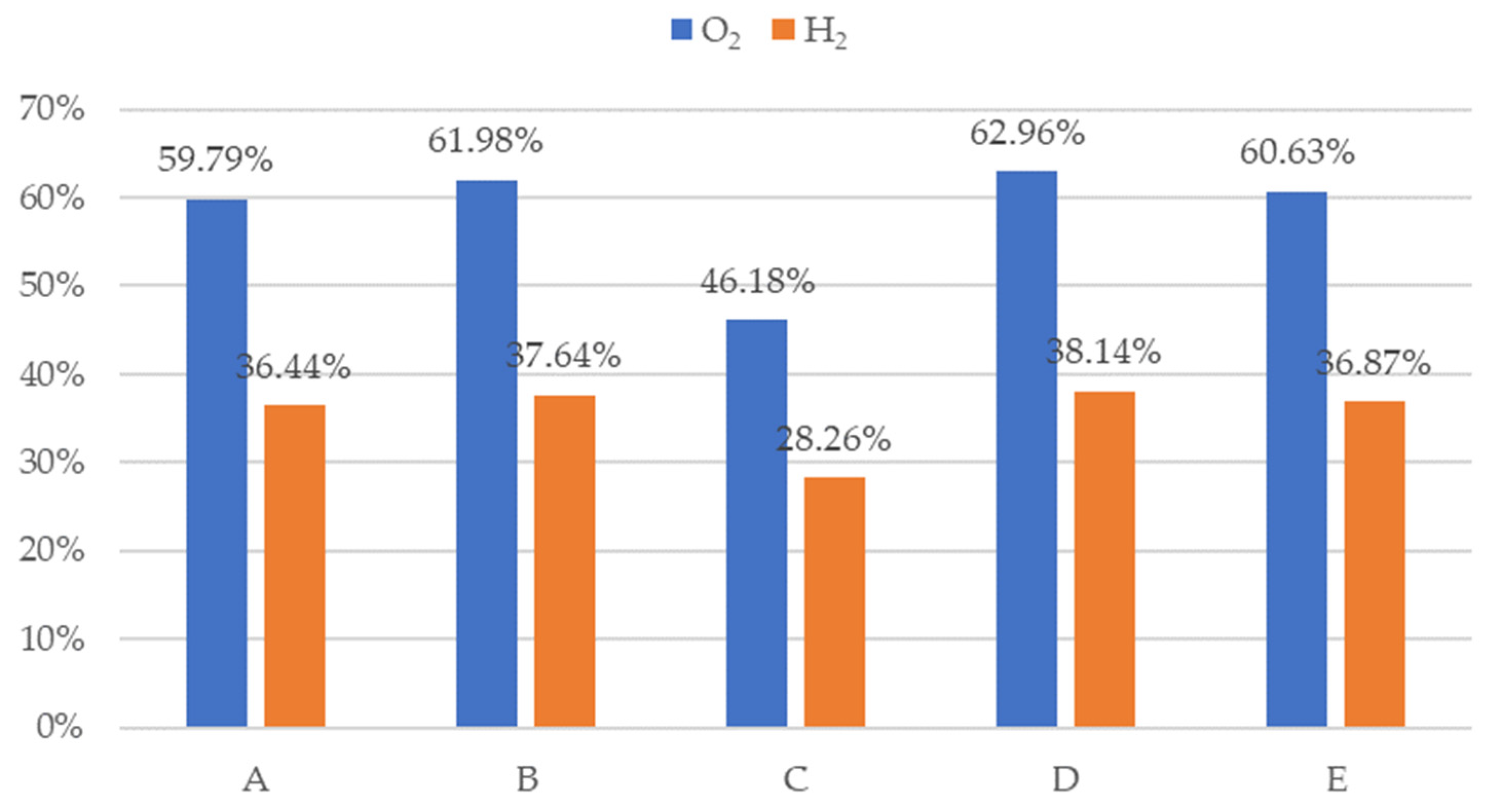
Figure 10 shows a comparison for the five simulated geometries of fuel and oxygen utilization percentages at 0.3 V. In accordance with the previously stated results, case D can use a higher quantity of fuel and oxidant. Specifically, oxygen utilization percentage is 62.96%, and hydrogen utilization percentage is 38.14%, thus achieving higher power values.
The obtained results indicate a clear superiority of the trapezoidal cross-section geometry as contact area is increased with respect to a traditional rectangular shape. Thus, the maximum power achieved in case D is 4.46% higher compared to case A, with same velocity values. Another important aspect to consider is velocity, as case B provides 3.21% more power at its peak compared to its homologous contact area in case A. Finally, the introduction of baffles generates higher local velocity areas as well as some turbulence that slightly improve the power generation by 1.29%, with respect to case A.

4. Conclusions

This research explored the effects of different channel geometries on the performance of Proton Exchange Membrane Fuel Cells, as there is a noticeable absence of in-depth analysis aimed at identifying designs that not only enhance performance but also harmonize with the cost-effective production methods mentioned in the literature. Using computational simulations, five channel geometries were analyzed, with case D featuring a trapezoidal cross-section, demonstrating the best performance due to an increased contact area with the reacting region, resulting in higher reaction rates and an improved overall performance.
On the other hand, case C had the worst performance, which was attributed to its smaller contact area despite its higher velocity. The study highlighted the importance of contact area in designing bipolar plates, suggesting that trapezoidal cross-section channels could be used to enhance performance without altering cross-sectional area and velocity. Moreover, the trapezoidal channels are easily manufacturable through sheet metal-forming techniques, since they introduce less strain during stamping than rectangular channels, fulfilling one of the objectives of the study.
Fuel and oxygen utilization percentages, with values of 38.14% and 62.96%, respectively, at 0.3 V, confirmed that case D, with its larger contact area, could utilize more fuel and oxidant, resulting in higher power values. The maximum power achieved in case D is 4.46% higher than in case A, a rectangular cross-section with the same velocity values. Current density values are also higher than other cases, with a value of 2.01 A/cm2 at 0.3 V, resulting in higher temperature, with a maximum of 74.89 °C at 0.3 V, and leading to a 4.46% power generation increase compared to base case A.
Additionally, the study also highlights the significance of velocity and turbulence, as seen in case B’s enhanced performance, with a current density value of 1.99 A/cm2 and an improvement of 3.21% in power generation compared to case A, which is attributed to its increased velocity, and case E’s advantage associated with localized high-velocity zones and turbulence generated by baffles. The introduction of baffles in case E generated higher local velocity areas and slight turbulence, leading to a 1.29% improvement in power generation compared to case A, as well as a current density value of 1.95 A/cm2 at 0.3 V. This finding indicates the potential for combining different channel geometries to further enhance the PEMFC performance.
In conclusion, the study emphasized the significance of contact area in bipolar plate design and proposed trapezoidal channels as a viable solution for improving the PEMFC performance. As a future direction, combining trapezoidal channels with small channel depths to increase velocity, along with the introduction of baffles, could offer even greater enhancements in the PEMFC performance. This study provides valuable insights for the optimization of metallic bipolar plates in PEMFCs, contributing to the development of more efficient and practical fuel cell technologies.

Author Contributions

R.B.: Conceptualization, Methodology, Software, Data curation, Writing—Original draft preparation, and Writing—Review and editing. M.B.: Data curation and Writing—Review and editing. A.B.: Conceptualization, Writing—Review and editing, and Supervision. A.L.: Writing—Review and editing. All authors have read and agreed to the published version of the manuscript.

Funding

This work was financially supported by the Catalan Government through the funding grant ACCIÓ-Eurecat (Project TRAÇA GreenH2).

Data Availability Statement

Data are contained within the article.

Conflicts of Interest

The authors declare no conflict of interest.

References

  1. Abdi, H.; Ait Messaoudene, N.; Kolsi, L.; Naceur, M.W. Modeling and Optimization of a Proton Exchange Membrane Fuel Cell Using Particle Swarm Algorithm with Constriction Coefficient. J. Therm. Anal. Calorim. 2021, 144, 1749–1759. [Google Scholar] [CrossRef]
  2. Choi, Y.; Win, M.Z.; Oo, W.; Min, J.; Ko, K.; Kim, Y.; Choi, H.; Chougule, S.S.; Khikmatulla, D.; Yi, K.B.; et al. Experimental Simulation Study on the Poisoning Effect of Hydrocarbon-Based Ionomers on Pt Catalysts for Fuel Cells. Electrochem. Commun. 2023, 157, 107602. [Google Scholar] [CrossRef]
  3. Khan, M.I.; Asfand, F.; Al-Ghamdi, S.G. Progress in Research and Technological Advancements of Thermal Energy Storage Systems for Concentrated Solar Power. J. Energy Storage 2022, 55, 105860. [Google Scholar] [CrossRef]
  4. Guédez, R.; Spelling, J.; Laumert, B.; Fransson, T. Optimization of Thermal Energy Storage Integration Strategies for Peak Power Production by Concentrating Solar Power Plants. Energy Procedia 2014, 49, 1642–1651. [Google Scholar] [CrossRef]
  5. Deepak Selvakumar, R.; Wu, J.; Ding, Y.; Alkaabi, A.K. Melting Behavior of an Organic Phase Change Material in a Square Thermal Energy Storage Capsule with an Array of Wire Electrodes. Appl. Therm. Eng. 2023, 228, 120492. [Google Scholar] [CrossRef]
  6. Hu, K.; Zhao, P.; Wang, S.; Wang, Y. Three-Dimensional Multiphase Simulation of a Partially Narrowed Flow Field Configuration for a High-Performance Polymer Electrolyte Membrane Fuel Cell. Appl. Therm. Eng. 2023, 223, 119986. [Google Scholar] [CrossRef]
  7. Zhang, J.; Wang, Z.; Ding, H.; Pan, Z.; Huang, X.; Pan, X. Heat and Mass Transfer Characteristics of a Novel Three-Dimensional Flow Field Metal Bipolar Plate for PEMFC by Laser 3D Printing. Int. J. Hydrog. Energy 2023. [Google Scholar] [CrossRef]
  8. Li, S.; Jin, R.; Li, S.; Wang, L.; Xie, Z.; Li, X.; Wang, Z. High Corrosion Resistance and Conductivity of Al2O3/CrN Coating for Metal Bipolar Plates in PEMFCs: Al2O3 Hinders CrN Columnar Crystals Growth. Int. J. Hydrog. Energy 2023, in press. [Google Scholar] [CrossRef]
  9. Hazar, H.; Yilmaz, M.; Sevinc, H. The Effects of Different Flow Field Patterns on Polymer Electrolyte Membrane Fuel Cell Performance. Energy Convers. Manag. 2021, 248, 114818. [Google Scholar] [CrossRef]
  10. Wilberforce, T.; El-Hassan, Z.; Khatib, F.N.; Al Makky, A.; Mooney, J.; Barouaji, A.; Carton, J.G.; Olabi, A.-G. Development of Bi-Polar Plate Design of PEM Fuel Cell Using CFD Techniques. Int. J. Hydrog. Energy 2017, 42, 25663–25685. [Google Scholar] [CrossRef]
  11. Hu, C.; Zhao, Y.; Zhang, Z.; Zhang, H.; Chen, D. Optimization of Flow Field Structure for Proton Exchange Membrane Fuel Cell Stack by Multi-Physics Coupling Simulation. Int. J. Electrochem. Sci. 2023, 18, 100195. [Google Scholar] [CrossRef]
  12. Arif, M.; Cheung, S.C.P.; Andrews, J. Numerical Investigation of Effects of Different Flow Channel Configurations on the 100 cm2 PEM Fuel Cell Performance under Different Operating Conditions. Catal. Today 2022, 397–399, 449–462. [Google Scholar] [CrossRef]
  13. Carcadea, E.; Ismail, M.S.; Ingham, D.B.; Patularu, L.; Schitea, D.; Marinoiu, A.; Ion-Ebrasu, D.; Mocanu, D.; Varlam, M. Effects of Geometrical Dimensions of Flow Channels of a Large-Active-Area PEM Fuel Cell: A CFD Study. Int. J. Hydrog. Energy 2021, 46, 13572–13582. [Google Scholar] [CrossRef]
  14. Limjeerajarus, N.; Charoen-amornkitt, P. Effect of Different Flow Field Designs and Number of Channels on Performance of a Small PEFC. Int. J. Hydrog. Energy 2015, 40, 7144–7158. [Google Scholar] [CrossRef]
  15. Al-Okbi, Y.; Al-murshedi, A.S.N.; Nemah, M.N.; Saad, H.A.K. Influence of Design Anode and Cathode Channel on (PEMFC) Fuel Cell Performance. Mater. Today Proc. 2021, 42, 2177–2184. [Google Scholar] [CrossRef]
  16. Xu, C.; Wang, H.; Cheng, T. Wave-Shaped Flow Channel Design and Optimization of PEMFCs with a Groove in the Gas Diffusion Layer. Int. J. Hydrog. Energy 2023, 48, 4418–4429. [Google Scholar] [CrossRef]
  17. Xu, C.; Wang, H.; Li, Z.; Cheng, T. Effects of the Design and Optimization of Trapezoidal Channels and Baffles (Number and Position) on the Net Power Density of Proton-Exchange Membrane Fuel Cells. ACS Omega 2022, 7, 4214–4223. [Google Scholar] [CrossRef]
  18. Xuan, L.; Wang, Y.; Mei, D.; Lan, J. Design and Modelling of 3D Bionic Cathode Flow Field for Proton Exchange Membrane Fuel Cell. Energies 2021, 14, 6044. [Google Scholar] [CrossRef]
  19. Neto, D.M.; Oliveira, M.C.; Alves, J.L.; Menezes, L.F. Numerical Study on the Formability of Metallic Bipolar Plates for Proton Exchange Membrane (PEM) Fuel Cells. Metals 2019, 9, 810. [Google Scholar] [CrossRef]
  20. Wilberforce, T.; Ijaodola, O.; Emmanuel, O.; Thompson, J.; Olabi, A.; Abdelkareem, M. Optimization of Fuel Cell Performance Using Computational Fluid Dynamics. Membranes 2021, 11, 146. [Google Scholar] [CrossRef] [PubMed]
  21. Zhang, Z.; Wang, Q.; Bai, F.; Chen, L.; Tao, W. Performance Simulation and Key Parameters In-Plane Distribution Analysis of a Commercial-Size PEMFC. Energy 2023, 263, 125897. [Google Scholar] [CrossRef]
  22. Tzelepis, S.; Kavadias, K.A.; Marnellos, G.E. A Three-Dimensional Simulation Model for Proton Exchange Membrane Fuel Cells with Conventional and Bimetallic Catalyst Layers. Energies 2023, 16, 4086. [Google Scholar] [CrossRef]
  23. Iranzo, A.; Gregorio, J.M.; Boillat, P.; Rosa, F. Bipolar Plate Research Using Computational Fluid Dynamics and Neutron Radiography for Proton Exchange Membrane Fuel Cells. Int. J. Hydrog. Energy 2020, 45, 12432–12442. [Google Scholar] [CrossRef]
  24. ANSYS, Inc. Chapter 21: Modeling fuel cells. In Fluent Theory Guide 2023 R2; ANSYS: Ann Arbor, MI, USA, 2023. [Google Scholar]
  25. Arif, M.; Cheung, S.C.P.; Andrews, J. Diagnostic Analysis of a Single-Cell Proton Exchange Membrane Unitised Regenerative Fuel Cell Using Numerical Simulation. Int. J. Hydrog. Energy 2021, 46, 29488–29500. [Google Scholar] [CrossRef]
  26. Arif, M.; Cheung, S.C.P.; Andrews, J. A Systematic Approach for Matching Simulated and Experimental Polarization Curves for a PEM Fuel Cell. Int. J. Hydrog. Energy 2020, 45, 2206–2223. [Google Scholar] [CrossRef]
  27. Al-Baghdadi, M.A.R.S. A CFD Model for Analysis of Performance, Water and Thermal Distribution, and Mechanical Related Failure in PEM Fuel Cells. J. Mechatron. Electr. Power Veh. Technol. 2016, 7, 7–20. [Google Scholar] [CrossRef]
  28. Hashemi, F.; Rowshanzamir, S.; Rezakazemi, M. CFD Simulation of PEM Fuel Cell Performance: Effect of Straight and Serpentine Flow Fields. Math. Comput. Model. 2012, 55, 1540–1557. [Google Scholar] [CrossRef]
  29. Woo, C.H.; Benziger, J.B. PEM Fuel Cell Current Regulation by Fuel Feed Control. Chem. Eng. Sci. 2007, 62, 957–968. [Google Scholar] [CrossRef]
  30. Baghban Yousefkhani, M.; Ghadamian, H.; Daneshvar, K.; Alizadeh, N.; Rincon Troconis, B.C. Investigation of the Fuel Utilization Factor in PEM Fuel Cell Considering the Effect of Relative Humidity at the Cathode. Energies 2020, 13, 6117. [Google Scholar] [CrossRef]
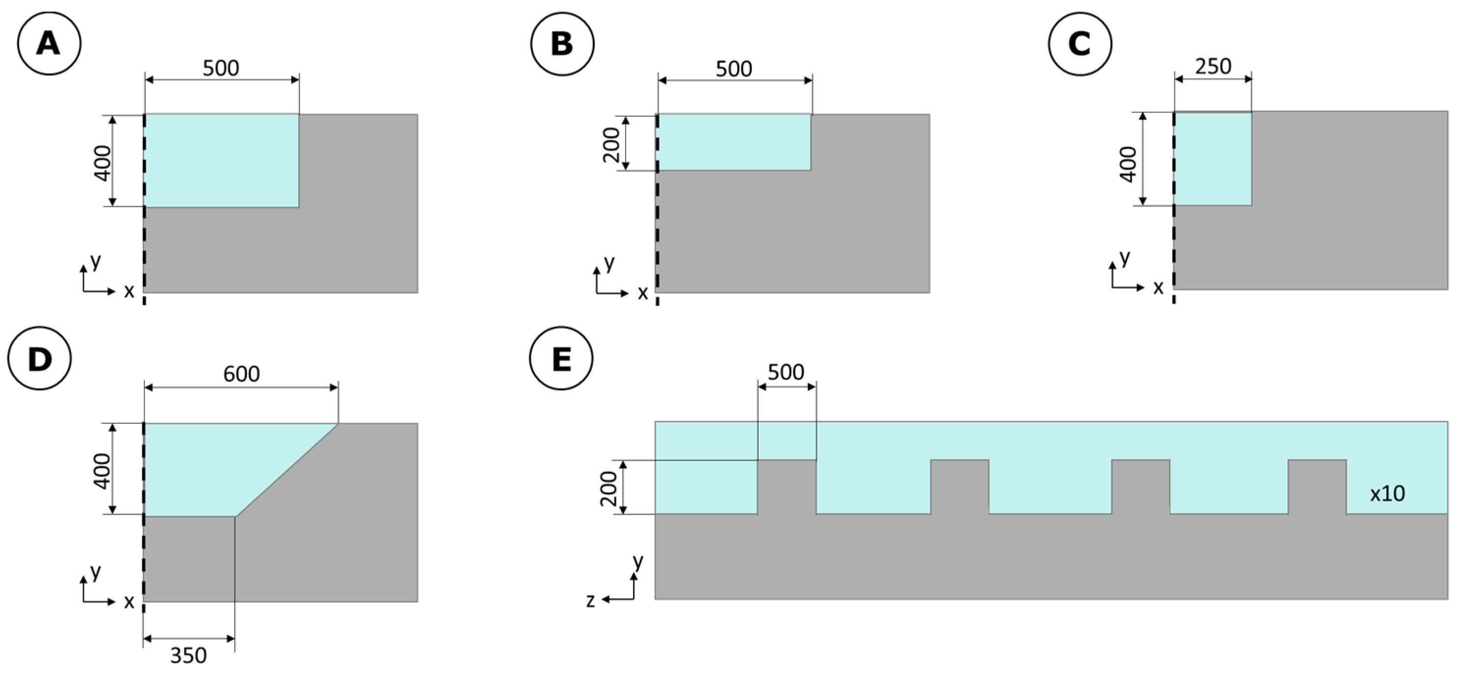
Figure 1. (AE) Cross-section of five geometries simulated in µm.
Energies 16 07702 g001
Figure 2. Simulated geometry and dimensions in µm.
Energies 16 07702 g002
Figure 3. Grid independence test.
Energies 16 07702 g003
Figure 4. Mesh details (case A).
Energies 16 07702 g004
Figure 5. Comparison of experimental and numerical results.
Energies 16 07702 g005
Figure 6. Polarization curves of the five simulated geometries.
Energies 16 07702 g006
Figure 7. Velocity streamlines details of case E.
Energies 16 07702 g007
Figure 8. Maximum temperature of the fuel cell over voltage of the five simulated geometries.
Energies 16 07702 g008
Figure 9. Temperature distribution at 0.3 V of case C (left) and case D (right).
Energies 16 07702 g009
Figure 10. Oxygen and fuel utilization percentages at 0.3 V of the five simulated geometries.
Energies 16 07702 g010
Table 1. Contact area and anode and cathode velocities for the five simulated geometries.
Contact Area (cm2)Anode Velocity (m/s)Cathode Velocity (m/s)
A0.502.223.56
B0.504.537.02
C0.254.447.08
D0.602.223.56
E0.502.22 *3.56 *
* Where cross-section is larger (equivalent to case A).
Table 2. Model input parameters.
Input ParametersValue
Anodic   exchange   current   density   ( j a n r e f )10,000 (A/m2)
Cathodic   exchange   current   density   ( j c a t r e f )10 (A/m2)
Anodic   charge   transfer   coefficient   ( α a n )1
Cathodic   charge   transfer   coefficient   ( α c a t )1
Faraday   constant   ( F )9.65 × 10⁴ (C/mol)
Universal   gas   constant   ( R )8.314 (J/(mol K))
Anode electrode specific active surface area ( ζ a n )20,000 (m−1)
Cathode electrode specific active surface area ( ζ c a t )20,000 (m−1)
Table 3. Boundary conditions.
RegionBoundary Condition
Anode channel inlet y H 2 = y H 2 , i n ;   y H 2 O = y H 2 O , i n ;   T i n , a n = T H 2 , a n ; m = m i n , a n
Cathode channel inlet y O 2 = y O 2 , i n ;   y H 2 O = y H 2 O , i n ;   T i n , c a t = T O 2 , c a t ;   m = m i n , c a t
Anode channel outlet φ z = 0
Cathode channel outlet φ z = 0
Anode terminal ϕ s o l = 0 ;   ϕ m e m y = 0 ;   T t e r , a n = T c e l l
Cathode terminal ϕ s o l = V c e l l ;   ϕ m e m y = 0 ;   T t e r , c a t = T c e l l
Exterior boundaries ϕ m e m x = 0 ;   ϕ m e m z = 0 ; ϕ s o l x = 0 ; ϕ s o l z = 0
Table 4. Operating conditions.
Operating ParametersValue
Cell temperature70 (°C)
Operating pressure2 (bar)
Anode mass flow rate1 × 10−7 (kg/s)
Anode H2 mass fraction at inlet0.60
Anode H2O mass fraction at inlet0.40
Cathode mass flow rate1.4 × 10−6 (kg/s)
Cathode O2 mass fraction at inlet0.21
Cathode H2O mass fraction at inlet0.05
Table 5. Material properties.
PropertyCatalystCurrent CollectorGDLMembraneMicro-Porous Layer
Density (kg/m3)27192719271919802719
Specific heat density (J/(kg K))8718718712000871
Thermal conductivity (W/(m K))1010010210
Electrical conductivity (S/m)5 × 1031 × 1065 × 1031 × 10−165 × 103
Porosity0.2-0.60.50.3
Permeability (m2)2 × 10⁻¹³-3 × 10−121 × 10−181 × 10−12
Disclaimer/Publisher’s Note: The statements, opinions and data contained in all publications are solely those of the individual author(s) and contributor(s) and not of MDPI and/or the editor(s). MDPI and/or the editor(s) disclaim responsibility for any injury to people or property resulting from any ideas, methods, instructions or products referred to in the content.