1. Introduction
The trend to reduce human impact on the climate and the environment, as well as the need to address the problem of the growing costs of energy carriers, caused the society members in general, and the users of hydraulic systems in particular, to express increasing expectations regarding improved performance and efficiency of hydraulic systems. This demand has resulted in intensified research efforts in the area of hydrostatic systems commonly used in the industry as power supply systems in machines. An analysis of the current development of hydrostatic systems suggests that it is performed in two parallel directions. The first and seemingly the main direction is to increase the efficiency-related parameters of hydrostatic systems, and as a result to limit their energy-consumption. In the view of the nowadays common transition from machines powered by combustion engines to machines powered by electric motors, this development direction offers savings resulting not only from lower energy costs, but also from longer operating times that the machine can reach before its batteries need to be recharged. The second research direction focuses on developing solutions in which the actuators have improved movement parameters, thus enhancing or even enabling the automation of technological processes based on the use of machines provided with hydrostatic drives.
The research works in the first direction are conducted with an aim to increase the efficiency of both the entire system and its individual components. One of the main elements in a hydrostatic system, which influences the efficiency of the entire system, is the pump with its control system. Some of the most recent publications have related methods for controlling pump parameters with the resulting system efficiency [
1,
2,
3,
4]. However, research in this area is performed mainly on the level of the entire systems, which are frequently based on novel electrohydraulic solutions and whose implementation requires the identification of their characteristics and of the influence of their control parameters on the response of the system. Electro-hydraulic Actuators (EHA), whose design results inter alia from attempts to reduce losses on hydraulic lines, are an important element in this research area. Current works focus on the identifying and describing of the dynamic phenomena which occur in this solution, as their influence has significantly increased due to shortened hydraulic lines [
5,
6]. Moreover, shortened hydraulic lines and direct connection to the cylinder (closed-loop circuit) cause the system to be increasingly affected by adverse dynamic phenomena in the pump, which have, in effect, again become the object of research interest [
7,
8]. Some research works also focus on developing such control systems for open-loop circuits that would improve their operating stability and time-related parameters [
9,
10,
11,
12,
13]. The proposed solutions include automatic control systems based on deep learning techniques in the area of position identification [
14]. Open-loop hydrostatic circuits are currently the main solution employed in the industry, and are likely to be used in the future. Their popularity results from the fact that in the classic architecture they have one central valve block which controls multiple receivers and is typically powered from one source. Research is currently performed into improving the operating characteristics by implementing a series of control solutions without manipulating the structure of the hydrostatic system [
15,
16,
17,
18,
19,
20]. Another, parallel research direction is to modify the classic structure of the system by adding a system which would allow the accumulation and reuse of the hydraulic energy, thus increasing the efficiency of the entire system [
21,
22]. However, it seems that the most interesting research direction is the one in which modifications are introduced into the classic architecture of the system. The literature mentions results of tests performed on systems with non-classic combination of three-way, three-position (3/3) valves integrated with an electric control system and used for controlling a cylinder under uncertain loads [
23]. However, the main recent development direction seems to be towards the analysis of hydraulic systems having distributed valve structure and employing two-way, two-position (2/2) valves. Such systems are integrated on the level of the electric control system [
24,
25,
26,
27,
28]. Attempts at developing electro-hydraulic systems with high dynamic parameters are also present in research on new electrically controlled valves [
29] and on systems employing multi-chamber cylinders [
30]. Some research publications also extend the analyses of hydraulic cylinder operation methods with issues related to their maintenance and reliability [
31].
This article presents the results of research and development works performed into hydrostatic systems used in heavy-duty machines, particularly in self-propelled mining utility vehicles. Hydrostatic systems used in this class of machines must satisfy a number of requirements regarding the safety, dimensions, and movement parameters of the operating elements which translate directly into the efficiency of the involved processes and into the possibility to implement advanced automation systems. The research works dedicated to this class of machines typically focus on the analysis of distributed control systems which are included in alternative architectures of hydrostatic systems. The analyses presented in this article are a part of a broader research program which is aimed at developing hydraulic systems having improved movement parameters and dedicated to work with advanced automation solutions employed in complex autonomous systems. Prior parts of this research have focused on analyzing the influence of the system architecture on the accuracy of the cylinder movement during its stopping process [
32]. This article analyzes the response time of a cylinder during the actuation of a boom system from the perspective of the phenomena related to the accumulation of hydrostatic energy in the power supply line. In the case of distributed system architecture, the performed research and development works demonstrated that the theoretical analyses of the cylinder response times during the initiation of the movement process were inconsistent with the experimental data. Further investigation into this problem allowed the formulation of a new approach in which the classic analysis of hydrostatic system response times is combined with the phenomenon which consists in the use of the pressure energy accumulated in the system. This article presents the analysis method, the test results and the summary of the proposed approach.
2. Background
The response time and accuracy of the movements performed by cylinders driving actuators of machines are two parameters which have gained importance over the past decades. This fact is the result of the development and deployment of work systems which have increased efficiencies, are frequently provided with partial or complete process automation, and which are required to maintain the accuracy and repeatability of the work movements. Therefore, the natural development direction in this area was to propose electronic control systems as a replacement to manually controlled hydrostatic drive systems in work machines. A significant progress in this approach was enabled by new designs of electro-hydraulic systems having an elastic electric control structure in which the control signals can be shaped practically without limitations. However, the application of electronic control systems and the resulting ability to modify the control signal with speeds on the order of kilohertzes has demonstrated how significant it is to allow for the dynamic and time-related parameters of the individual elements and the entire hydraulic systems, which are capable of a stable operation with control signals varying within several hertzes. As a result, the knowledge base used in the analysis of hydraulic systems should be extended to involve investigations of phenomena whose influence was negligible in the classic systems but has become significant in the current solutions. One of such problems is to measure the response time of a cylinder under an external load at the moment when its movement starts, i.e., when it is actuated. In the classic analysis of this response time, valve opening times are the basic considered parameters. In the case when the system comprises long hydraulic lines, the analysis also includes the time resulting from the propagation of the pressure wave. However, tests performed on hydrostatic systems with distributed control structure have demonstrated that the response times calculated on the basis of the above approach are not consistent with the results of experiments. The results become consistent only after allowing for the influence of the pressure energy accumulated in the power supply line, although this parameter was ignored in classic solutions and analyses. This article proposes an experimentally verified method for the analysis of the response times of the hydraulic cylinder upon its actuation.
3. Problem Description
3.1. Research Thesis and Description of the Analyzed Systems
It is commonly accepted that the response time of a cylinder which is an actuator in a hydrostatic system and which starts its movement depends mainly on the response time of the valve to the change of the control signal. This assumption, which is entirely independent and which does not take into consideration the structure of a hydraulic system, has been accepted as preliminary in preparing tests which would verify the formulated thesis that the structure of a hydrostatic system, and thus the influence of the accumulated pressure energy, has a significant influence on the response times observed when the cylinder under external load starts its movement. Based on the above, three hydrostatic systems supplying power to the cylinder were selected for tests and analyses (
Figure 1):
A classic system controlled with a four-way, three-position (4/3) directional control valve, in which the pump is connected to the tank in the central position—referred to as system 1;
A two-way, two-position (2/2) valve control system installed on the cylinder power supply line—system 2;
A two-way, two-position (2/2) valve control system installed on the cylinder return line—system 3;
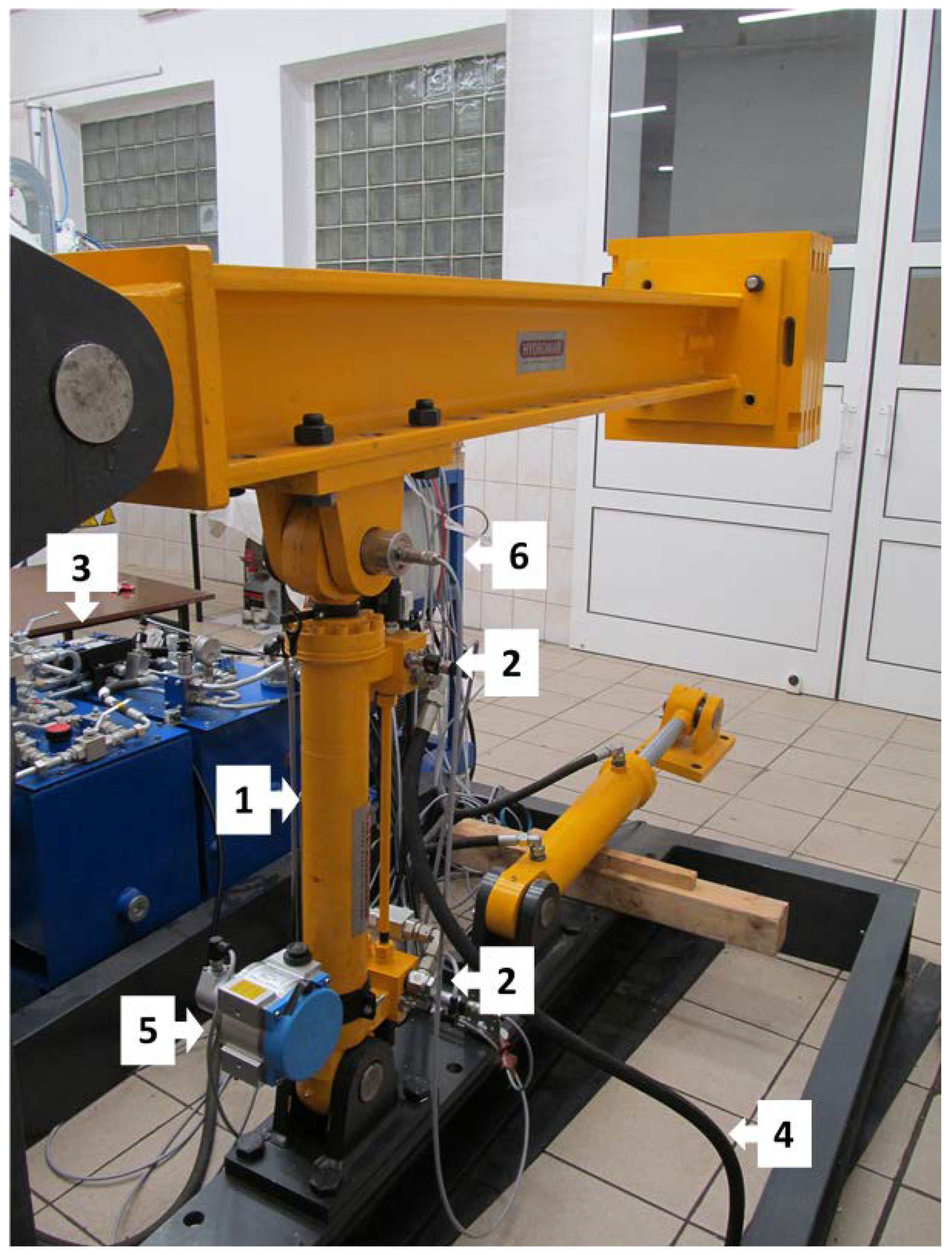
The systems shown in
Figure 1 were installed on a test stand comprising a boom system (
Figure 2). The aim of the pilot tests performed in the next step was to identify such a position for the cylinder in the system provided with a mass load of 500 kg installed at the end of the boom that would prevent the maximum pressures in the supplied chamber during startup from exceeding 85% of the pressure value set on the relief valve. As a result, it may be assumed that when the cylinder under load was actuated, the pressure relief valve did not open due to pressure rise in the power supply line. This hydraulic system was used in all tests, and only the control system was modified. Therefore all parameters of the system were identical, enabling a comparative analysis. The employed hydraulic oil was HLP type with the 68 viscosity grade. All of the tests were performed on the warm hydrostatic system—the oil temperature was 45 ÷ 55 °C.
The test stand was provided with an option to record the investigated parameters at a frequency of 500 Hz. As the parameters included the electric signal controlling the valves responsible for the cylinder extension, the time required for valve reconfiguration could be precisely measured. The actuation time of the cylinder was identified with the use of an accelerometer installed on the cylinder. The measurements also involved pressure values in the piston chamber. The power-supply part of the hydrostatic system, together with the pressure relief valve and the 4/3 directional control valve, were connected to the cylinder with a line 4930 mm long and comprising an elastic hydraulic hose 4000 mm in length.
Table 1 presents the basic parameters of the hydraulic system.
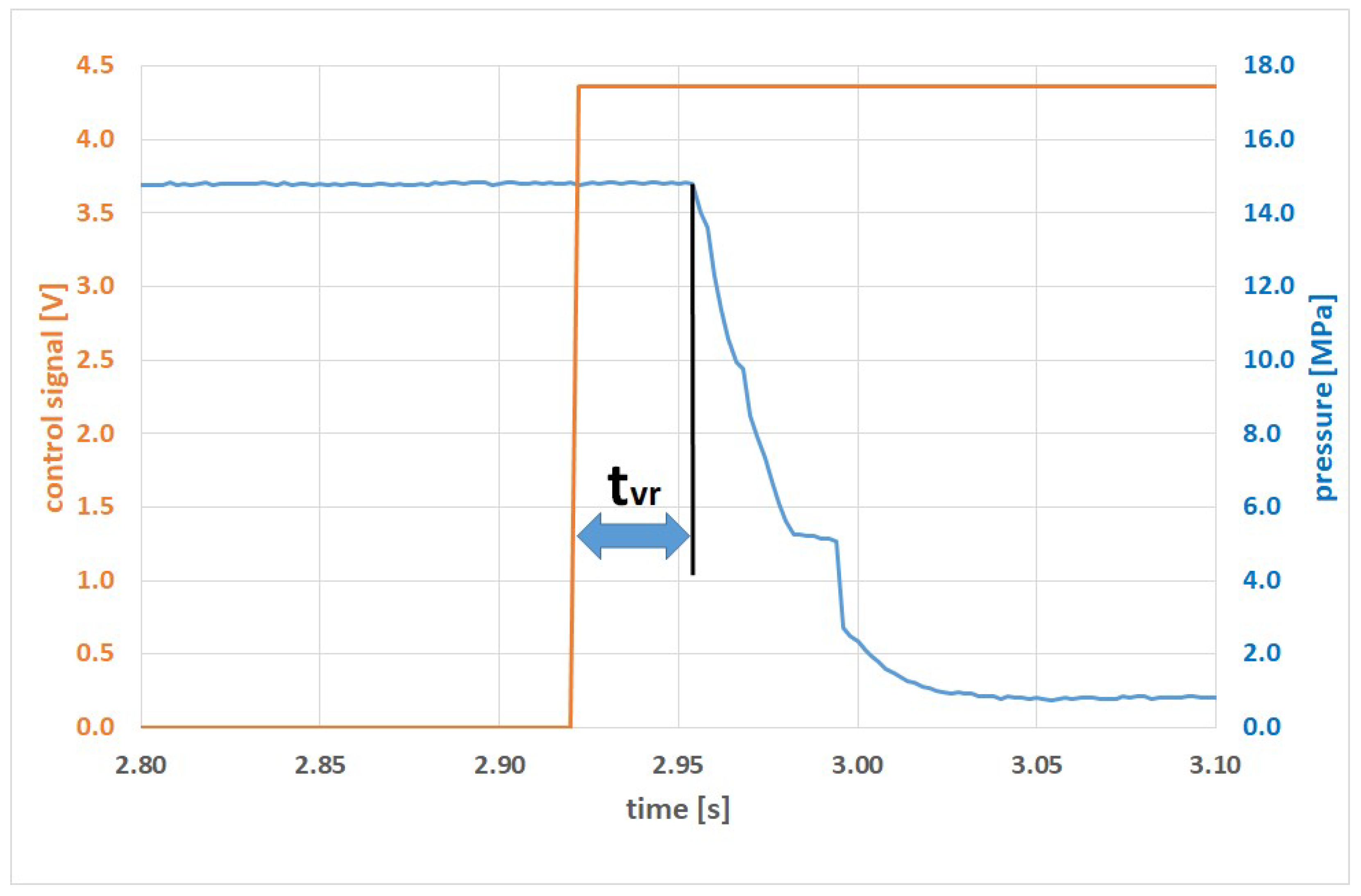
For the purpose of further analyses, the response times for individual valves were identified experimentally by measuring the duration between the modification of the control signal and the change of pressure in the independent system, which indicated that the valve was open (
Figure 3). A series of five tests was performed for each valve, and the resulting times were averaged and rounded to the nearest thousandth. The following results were obtained:
The response time for the 4/3 valve (system 1)—tvr_1 = 42 ms for pressure difference close to zero (standard deviation of population for the results was 8 × 10⁻⁴ s);
The response time for the 2/2 valve on the power supply line (system 2)—tvr_2 = 29 ms for pressure difference equal to 12 MPa (standard deviation of population for the results was 20 × 10−4 s);
The response time for the 2/2 valve on the return line (system 3)—tvr_3 = 34 ms for pressure difference equal to 18 MPa (standard deviation of population for the results was 15 × 10−4 s);
Note that in the case of the 2/2 valve installed on the return line, the tests were performed for the pressure difference equal to 18 MPa, as due to the different piston face areas, the pressure in the piston rod chamber was 18 MPa when the piston chamber was supplied with liquid at a pressure of 12 MPa.
3.2. Analysis of the Response Times without Consideration for the Energy Accumulation
Based only on the experimentally identified valve opening times, it may be concluded with some degree of approximation that as the opening time of the 4/3 valve corresponds to the theoretical response time of the system, as the beginning of the movement process depends only on the reaction of this valve. A more precise identification of the response time requires allowing for thepropagation time of the pressure wave in the power supply line. As a result, the response time of system 1 should be extended with the time (t
wp) required for the pressure wave to propagate from the 4/3 valve to the piston chamber. This time is calculated from the following relationship:
With the pressure wave propagation speed in hydraulic oil (vwp) assumed at 1400 m/s, the pressure wave propagation time (twp) in the power supply line (ls) is 3.5 ms. In comparison to the response times of the valves, this value is lower by an order of magnitude and therefore should be theoretically negligible to the response times of the system upon cylinder actuation. Therefore, in system 1 the response time of the actuated cylinder, expressed as a function of the response time of one 4/3 valve and a relatively short pressure wave propagation time, theoretically seems to be the shortest.
In the case of systems 2 and 3, two valves must be reconfigured in order to maintain liquid supply to the system, and this fact theoretically increases the response time of a cylinder actuated under mass load. The first valve is the 2/2 controlled valve, and the second is the pressure relief valve (No. 4 in
Figure 1), which is open at the moment of opening the 2/2 valve allowing the liquid to flow to the tank. Therefore, the theoretical process of starting the cylinder movement in systems 2 and 3 involves the following steps:
Transmission of the control signal and the subsequent opening of the 2/2 valve;
Propagation of the lower pressure wave from the cylinder to the pressure relief valve in the power supply system;
Closure of the pressure relief valve.
If the additional response time of the pressure relief valve is included in the calculations, system 1 should theoretically, in classical analysis, have the shortest response time when the cylinder under external load is actuated. However, such a conclusion is not confirmed by experimental tests, as discussed below.
4. Results of Experimental Tests
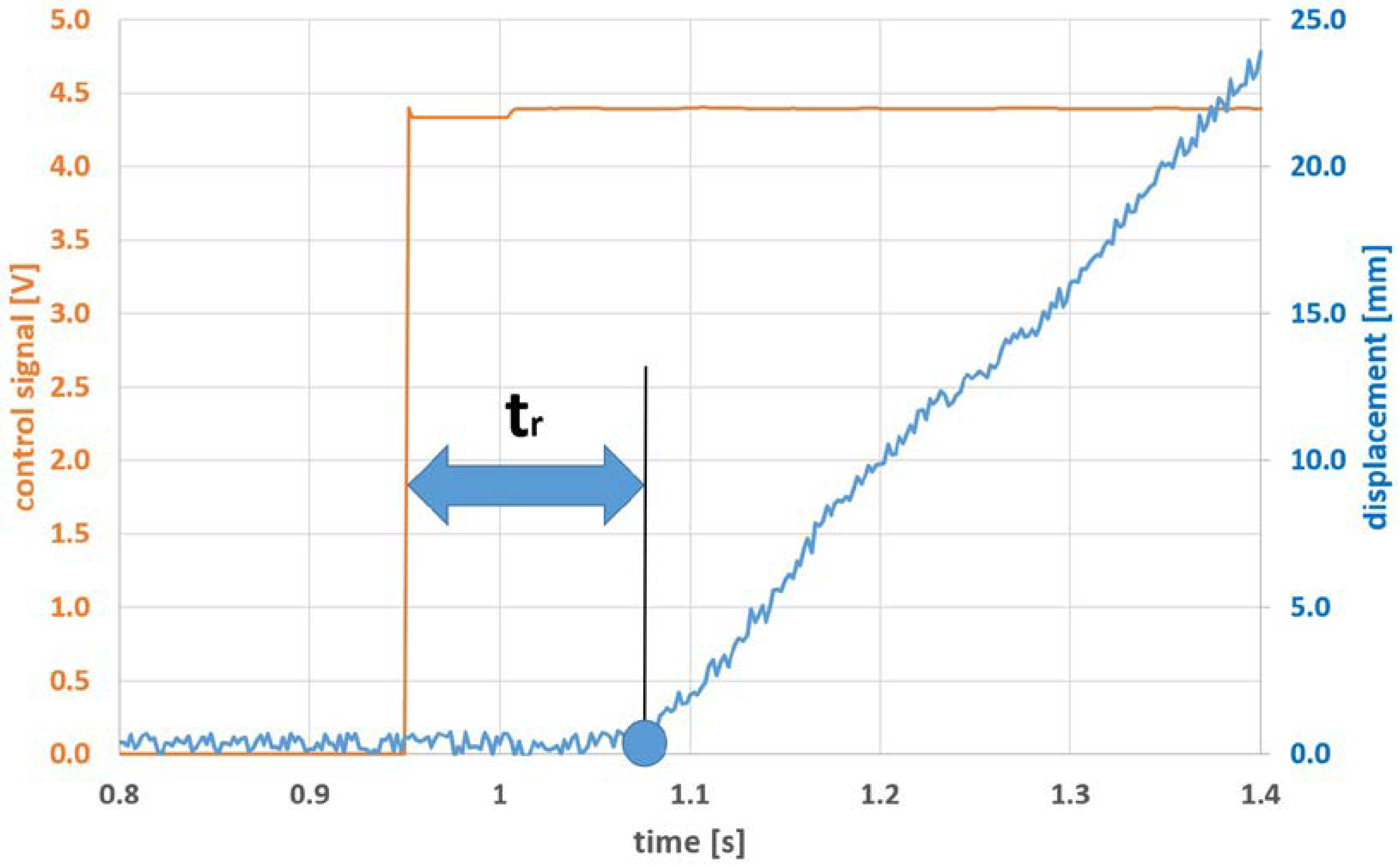
The tests were performed on the test stand described above. They were aimed at identifying the response times of the cylinder driving the boom system under external load. When the movement process started, the boom was completely retracted. The recorded values included the value of the control signal which was changed rapidly. The cylinder extension was measured with a draw wire encoder. The time difference between the signal change and the cylinder actuation could be identified by comparing the time difference between the modification of the control signal and the moment at which the cylinder movement started (
Figure 4). In addition, the pressure value in the piston chamber was measured during the tests.
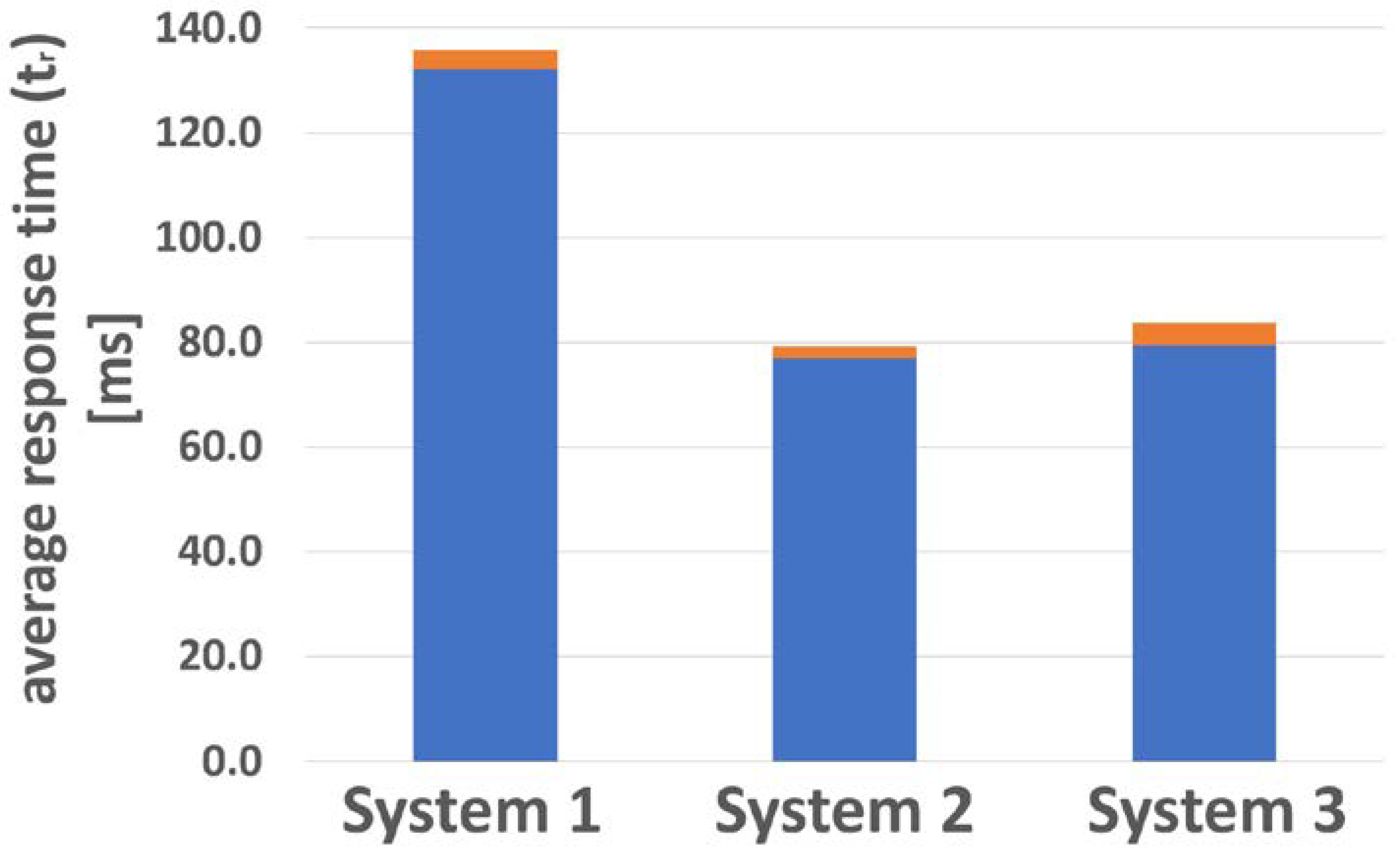
The tests of individual control systems were repeated in five series, and the results were statistically processed (
Table 2) and graphically represented in
Figure 5.
The test results indicate that the classic solution with the 4/3 valve (system 1) has the longest response times—at an average of 134 ms. The average response times for the cylinder controlled with 2/2 valves in blocks installed directly on the cylinder were 78 ms in the case of system 2 (with the valve on the power supply line to the piston chamber) and 81.6 ms in the case of system 3 (with the valve on the return line from the piston rod chamber).
In order to identify the response time of the system after the control valve is opened (t
sr), the opening times (t
vr) identified in the previous experiment for individual valves were subtracted from the obtained results in accordance with the following relationship:
Thus, the average response times of the system after opening the control valves (tsr) were as follows:
System 1—tsr_1 = 92.0 ms;
System 2—tsr_2 = 49.0 ms;
System 3—tsr_3 = 47.6 ms;
These results do not correspond with the conclusions suggested on the basis of the classic analysis in
Section 3.2. Rather, they demonstrate that the 2/2 valve control systems installed directly on the cylinder have significantly shorter response times to the control signal upon the actuation of the cylinder under external load. The response time is shorter in spite of the fact that according to the classic approach, the movement of the cylinder in systems 2 and 3 requires the additional closure of the pressure relief valve in the power supply system—and this valve remains closed when the cylinder movement starts in system 1. The above results and conclusions have become the basis for developing a broader analytical approach to the identification of hydrostatic system response times.
5. Analysis of the Hydrostatic System Response Time with Consideration for the Accumulated Pressure Energy
The observed differences of response times between the investigated systems should be related to the energy present in the system at the moment of valve reconfiguration. In the case of system 1, the hydraulic power supply line to the cylinder is under atmospheric pressure until the 4/3 valve is opened and the line is connected with the pump. On the other hand, in the case of systems 2 and 3, before the control valves are opened the power supply line is under a pressure defined by the settings of the pressure relief valve. In the analyzed case, this value was 12 MPa. It can be therefore concluded that unlike systems 2 and 3, system 1 did not have pressure energy accumulated in the power supply line. The value of the accumulated energy depends on the pressure in the power supply line and on the parameters of both the line and of the hydraulic oil. For the purpose of the analyses, an assumption was made that the deformation due to pressure difference affects only the elastic segment of the line (No. 8 in
Table 1), and the change of liquid volume due to pressure change is observed along the entire power supply line. The total change of the volume of liquid in the line (ΔV) can be therefore described as the sum of volume changes due to changes of pressure exerted on the elastic hose and on the liquid:
Allowing for the initial volume of liquid in the elastic hose (V
h_0) and in the entire power supply line (V
l_0), the elasticity moduli of the hose (E
h) and of the liquid (E
l) can be used to calculate the total change of volume as a function of pressure difference (Δp). The values of elasticity moduli used in the calculations are listed in
Table 3.
Therefore, in the case when the pressure in the power supply line to the cylinder increases by 12 MPa, the resulting volume difference is 10.86 × 10
−6 m
3. Calculations performed on the basis of the pump efficiency indicate that such volume is pumped within 0.03 s. This volume change is a value necessary in calculating the accumulated energy on the basis of elastic phenomena in the power supply line from Equation (4).
For pressure difference Δp = 12 MPa, the calculated energy is 65.15 J. In the analyzed case, the static force exerted on the cylinder before its actuation was 30 kN. Allowing for the piston face area, it can be therefore assumed that the forces acting on the piston were balanced at the pressure value of 6 MPa, and that this is the pressure value required to actuate the cylinder.
Thus, after the valve is reconfigured in system 1, liquid is first pumped to the power supply line, causing a pressure rise. In order to reach the pressure value required to start the movement of the cylinder (6 MPa), the power supply line must accommodate the volume of liquid equal to 5.43 × 10⁻⁶ m3 at the time of 15 ms. Further, this time should be added to the propagation time of the increasing pressure wave, equal to 3.5 ms. Thus the sum total of the system delay time due to the above phenomena is not less than 18 ms.
In systems 2 and 3 the opposite effect is observed. When the valves are reconfigured, the pressure value decreases as the accumulated energy is returned to the cylinder. In this case, the 6 MPa pressure difference is equivalent to the accumulation of 48.86 J of energy, which is transferred directly to the cylinder. The accumulated energy is sufficient to overcome the resistance to motion and extend the cylinder by approximately 1.6 mm. In such cases, it can be therefore assumed that the initial movement of the cylinder is performed with the use of the accumulated energy and that it is accompanied by the propagating wave of decreasing pressure, causing closure of the pressure relief valve. After the pressure relief valve is closed, the energy received by the cylinder is supplied only from the pump. The additional reduction of the response times of systems 2 and 3 with respect to system 1 results from the characteristics of pressure changes in the cylinder. In the case of system 1, the pressure increases, and therefore the cylinder is actuated with significantly lower dynamics than in the case when the pressure difference in the cylinder chambers sharply increases after the control valves are opened, as in systems 2 and 3. As a result, in the analyzed case the difference in response times for systems 1, 2 and 3 after opening the control valves (tsr) was approximately 43 ms, with as much as 25 ms being due to the pressure values in the cylinder chambers at the moment of opening the control valves, and thus due to the dynamics of the cylinder actuation process. It should be noted that the differences observed for the response times of systems 2 and 3 are practically negligible, clearly suggesting that the energy accumulation in the power supply line is a significant phenomenon, and that the impact of the pressure differences in the cylinder chambers before cylinder actuation can be ignored in the analysis of the influence of accumulated energy on the start time of the movement process.
6. Conclusions
The theoretical analysis and the results of experiments presented above confirm the research thesis that the structure of a hydrostatic system and the related favorable or unfavorable impact of the accumulated pressure energy in the hydraulic lines have a significant influence on the response times observed when the cylinder under external load is actuated. The differences between the response times of the systems after opening the control valves have been here described and explained with the use of an analysis method allowing for the phenomenon of energy accumulation in the power supply line. The differences between the actual response times of the tested hydrostatic systems were from 52 to 56 ms, i.e., approximately 40% in favor of the systems controlled with 2/2 valves installed on the cylinder. The proposed extended approach to the analysis of the influence of the accumulated pressure energy in the power supply line allows the system response times to be related not only with the valve response times but also with the structure of the hydrostatic system, if the energy accumulation in the power supply line is taken into consideration. With the here proposed analysis method, it is possible to:
Estimate the expected response times during the actuation of various hydrostatic power supply systems already in their design process;
Introduce informed modifications to the structure of the hydrostatic system in order to improve its response time during the process of initiating the movement of the actuator in the already existing designs;
The above research results contribute to works on developing new, high-efficiency electro-hydraulic drive systems for heavy-duty machines.


