Article

Decomposition of the Voltages in a Three-Phase Asymmetrical Circuit with a Non-Sinusoidal Voltage Source

Department of Energy, Faculty of Mechanical Engineering, Koszalin University of Technology, 15-17 Raclawicka St., 75-620 Koszalin, Poland
*
Author to whom correspondence should be addressed.
Energies 2023, 16(22), 7616; https://doi.org/10.3390/en16227616
Submission received: 12 September 2023 / Revised: 8 October 2023 / Accepted: 14 November 2023 / Published: 16 November 2023
(This article belongs to the Section F1: Electrical Power System)

Abstract

:
This article presents the concept of a mathematical description of a three-phase, four-wire asymmetrical electric circuit in decomposition into Voltages’ Physical Components (VPC), associated with distinctive physical phenomena in the load. This is an alternative method of mathematical description to the Currents’ Physical Components (CPC) still being developed since the end of the last century. According to previous studies, the improvement of the power factor in three-phase systems is possible by observing several components. Compensation for the scattered power is possible only by using a reactive compensator connected in series with the load. Thanks to the presented analytical method, it is possible to design compensators connected in series with the load. The VPC power theory opens the possibility of improving the power factor in three-phase networks for loads with asymmetry between phases. Due to the unfavorable impact of high currents on the compensator branches, the method proposed in the article can improve the energy quality in local low-power grids. However, the possibility of its practical use in high-power industrial networks is questionable.

1. Introduction

Actions that reduce the energy intensity of the power system are forced by the modern development of the energy economy. In addition to activities performed in the production and receiving area, the distribution area is also an important element. An important factor here is to take care of the appropriate reduction in the current value flowing in the power system [1]. The key tools for understanding the phenomena that cause increased current flow in an electrical circuit are mathematical methods of describing the flow of energy. Knowing the nature of the physical energy interactions in the load, it becomes possible to take action to improve the power factor. One of the basic activities is power compensation.
There are known methods of power compensation using parallel reactive compensators [2,3,4]. This is the basic method of compensation, which has many practical solutions [5,6,7,8], the essence of which is to select the appropriate value of reactance connected in parallel with the load. The optimal solution here is to use the theory of Shepherd and Zakikhani [9], but one should remember the inaccuracies of this method. The CPC theory [10,11,12,13,14], whose evolution has accelerated in recent years, can be used to determine the compensator parameters more precisely. Further references can be found in [15,16,17,18,19,20]. The description of single-phase circuits is discussed in [15,21] and for three-phase, four-wire circuits in [22,23,24]. Recent improvements in this power theory [3,7,25,26] enable a complete mathematical description of the electrical quantities in real three-phase circuits. In addition, thanks to the distribution of the current into individual components, it is possible to analyze the circuit in various situations that occur in real systems [27,28,29,30]. Based on the CPC theory, power compensation methods have been developed [31,32,33] and special attention should be paid to [34,35,36]. When changes in electrical parameters in the circuit are taken into account, adaptive algorithms [25,26] are very important. According to the conclusions presented in this literature, it is possible to improve the power factor to satisfactory values, but due to the presence of the scattered component, complete compensation cannot be achieved.
Other alternative methods for analyzing single-phase [37,38,39,40,41] and three-phase [42,43,44,45,46] electrical circuits have also been described in the literature, but due to the methodology used in them, they do not provide a solution to the problem posed in this article. These theories were also used to develop algorithms determining the parameters of the compensator [47,48,49,50,51]. The authors of [52] present a comparison of several compensation methods. A common feature of all compensation methods is the use of resonant circuits [53,54,55]. In the case of parallel compensation, current resonance is used. The classic way to compensate for reactive power in high-power industrial networks is to use a synchronous compensator—a synchronous electric machine of a rotating type with electromagnetic excitation, operating in motor mode at idle speed. However, this classical method does not compensate for load asymmetry across phases.
For the correct assessment of electrical parameters before and after compensation, an appropriate method of power measurement [56,57,58,59] should be adopted. When the analysis takes into account the nonlinearity of the load [29,60,61,62], additional analytical problems will appear. The appearance of many harmonics in current and voltage waveforms means that the compensator should be selected for all signal frequencies [63,64,65]. Then, additional voltage and current filtration [33,66,67,68] are required.
This article presents a mathematical analysis that enables a different method of power compensation, one that is able to reduce the impact of the scattered component on the efficiency of the power system. For this purpose, voltage resonance is used, i.e., power compensation is also possible in a series connection. Such a compensation method may have little practical use; however, it should be treated as an alternative to modern compensation methods and an attempt to answer the following question: is complete compensation possible in the power system?
In order to discuss the series reactive compensator, it is first necessary to decompose the electrical quantities into Voltages’ Physical Components.

2. Decomposition into Three-Phase Voltages’ Physical Components

The only possibility to reduce the scattered component is to change the load supply conditions by adding a reactive compensator connected in series with the load. To do this, the voltage distribution should be presented analogously to the CPC theory [5,6,11].
In the case of non-sinusoidal periodic waveforms, the three-phase current and voltage quantities can be represented as the sum of individual harmonics
u = n u n = 2 · e n U ¯ n · e j n ω 1 t , i = n i n = 2 · e n I ¯ n · e j n ω 1 t .
This means that the vectors of currents and voltages for harmonic waveforms can be defined as follows:
u n = df u R n u S n u T n ,   U ¯ n = df U ¯ R n U ¯ S n U ¯ T n ,
i n = df i R n i S n i T n ,   I ¯ n = df I ¯ R n I ¯ S n I ¯ T n .
Across the transformer (Figure 1) are transferred voltage harmonics with positive and negative sequences. Symmetrical harmonics of zero sequences are not transferred from the source to the secondary side of the transformer. Such harmonics will only appear on the secondary side of the transformer when zero sequence harmonics have been generated by the load.
The three-phase load (Figure 1) can be decomposed into individual components responsible for various physical phenomena occurring in this circuit. Analogously to the CPC theory [22], the three-phase vector (1) of voltage u will be decomposed into voltage components which, in the physical sense, will reflect the behavior of the system on the impact of individual phenomena.
Active component of three-phase vector of voltage ua in the physical sense is a part of the supply voltage which, with unchanged supply current, causes unchanged active power on a three-phase resistive load. It is the most important component that describes the influence of active power on the electrical quantities supplying the load. Analogous to the equivalent conductance Ge in the CPC theory, in the voltage distribution, the equivalent resistance Re is defined for the n-th harmonic in terms of the useful active power P at three-phase current i.
R e n = df P n i n 2 = 1 m R R n + R S n + R T n .
where m—multiple of active phases, e.g., for a single-phase load connected to the R phase of a three-phase network will be Re(n) = RR(n). If there is no resistance in a given phase, insert zero.
The equivalent resistance Re(n) is related to the voltage component, which for the n-th harmonic is:
u c n = R e n · i n = 2 e R e n · I ¯ n · e j n ω 1 t .
The total impact of all harmonics affects the uc component, the resultant value of which is:
u c = n u c n = 2 e n R e n I ¯ n e j n ω 1 t .
The resistance Re(n) may vary with the order of the harmonic, in which case a scattered component of voltage will appear. A change in the Re(n) value means a change in the real part of the equivalent impedance of the load. Such changes in the series connection of resistance and reactance cannot be observed, but when the resistance and reactance are connected in a parallel or mixed way, it is possible. The constant component, which is independent of the order of the harmonic, depends on the resultant active power and the value of the equivalent resistance Re.
R e = df P i 2 .
Let us define unit three-phase vectors of the positive, negative, and zero sequence
1 p = df 1 α * α , 1 n = df 1 α α * , 1 z = df 1 1 1 , α = 1 e j 2 π 3 , α * = 1 e j 2 π 3 .
In the four-wire system, in the absence of symmetry, the currents in the phase conductors for the n-th harmonic are described by symmetrical components, which can be determined from the relationship:
I ¯ n z I ¯ n p I ¯ n n = 1 3 1 1 1 1 α α * 1 α * α · I ¯ R n I ¯ S n I ¯ T n .
The active component of the voltage and its RMS value is:
u a = 2 e n R e I ¯ n e j n ω 1 t = 2 e n R e 1 p I ¯ n p + 1 n I ¯ n n + 1 z I ¯ n z e j n ω 1 t , u a = P i .
The remaining component in uc, which reflects changes in the equivalent resistance Re(n) with the order of the harmonic, should be defined as the scattered component of voltage, which is:
u s = u c u a = 2 e n R e n I ¯ n e j n ω 1 t 2 e n R e I ¯ n e j n ω 1 t = = 2 e n R e n R e · 1 p I ¯ n p + 1 n I ¯ n n + 1 z I ¯ n z e j n ω 1 t .
The RMS value of the scattered component is:
u s = n R e n R e 2 i n 2 .
The reactive nature of the circuit is described by reactive components. Knowing the reactance of the receiver, the equivalent reactance can be determined, which is:
X e n = df Q n i n 2 = 1 m X R n + X S n + X T n .
From dependencies (4) and (13), the formula for the equivalent impedance is:
Z ¯ e n = df R e n + j X e n = 1 m Z ¯ R n + Z ¯ S n + Z ¯ T n .
The equivalent reactance (13) is associated with a component consistent with the phase sequence of the power source, which can be called the reactive component of voltage ur:
u r n = 2 e j X e n · 1 p I ¯ n p + 1 n I ¯ n n + 1 z I ¯ n z · e j n ω 1 t .
The RMS value of the reactive component is:
u r = n X e n 2 i n 2 .
When the load is unbalanced, the n-th harmonic of the voltage additionally contains an unbalanced component, which is:
u u n = u n u c n u r n .
The unbalanced component of voltage uu (17) is asymmetric, so according to the method of symmetrical components it can be represented as a sum of vectors of symmetrical components with the following sequence: positive, negative, and zero, respectively:
u u n = u u n p + u u n n + u u n z .
From dependencies (17), (6), and (15), we obtain:
u u n = u n u c n u r n = = 2 e u n Z ¯ e n 1 p I ¯ n p + 1 n I ¯ n n + 1 z I ¯ n z · e j n ω 1 t .
The unbalanced component of voltage can be expressed by quantities describing a three-phase load. For a symmetric component with a positive sequence, it will be:
u u n p = 2 e Z ¯ R n Z ¯ e n Z ¯ S n Z ¯ e n · α * Z ¯ T n Z ¯ e n · α · I ¯ n p e j n ω 1 t
For a symmetric component with a negative sequence, it will be:
u u n n = 2 e Z ¯ R n Z ¯ e n Z ¯ S n Z ¯ e n · α Z ¯ T n Z ¯ e n · α * · I ¯ n n e j n ω 1 t
while for a symmetric component with zero sequence it will be:
u u n z = 2 e Z ¯ R n Z ¯ e n Z ¯ S n Z ¯ e n Z ¯ T n Z ¯ e n · I ¯ n z e j n ω 1 t
These vectors are mutually orthogonal, so for RMS values the following is correct:
u u n 2 = u u n p 2 + u u n n 2 + u u n z 2 .
In addition, analogously to (9), one can write:
U ¯ u n z U ¯ u n p U ¯ u n n = 1 3 1 1 1 1 α α * 1 α * α · U ¯ R u n U ¯ S u n U ¯ T u n
In a three-phase circuit, harmonics can be considered in terms of symmetrical components. This means that for harmonics in a positive sequence, one gets:
U ¯ u n z U ¯ u n p U ¯ u n n = 1 3 1 1 1 1 α α * 1 α * α · Z ¯ R n Z ¯ e n Z ¯ S n Z ¯ e n · α * Z ¯ T n Z ¯ e n · α · I ¯ n p = = 1 3 Z ¯ R n + α * Z ¯ S n + α Z ¯ T n 0 Z ¯ R n + α Z ¯ S n + α * Z ¯ T n · I ¯ n p = Z ¯ u n z 0 Z ¯ u n n · I ¯ n p ,
where Z ¯ u n —the unbalanced impedance {XE “impedancja niezrównoważenia”}.
For harmonics in negative sequence, one gets:
U ¯ u n z U ¯ u n p U ¯ u n n = 1 3 1 1 1 1 α α * 1 α * α · Z ¯ R n Z ¯ e n Z ¯ S n Z ¯ e n · α Z ¯ T n Z ¯ e n · α * · I ¯ n n = = 1 3 Z ¯ R n + α Z ¯ S n + α * Z ¯ T n Z ¯ R n + α * Z ¯ S n + α Z ¯ T n 0 · I ¯ n n = Z ¯ u n z Z ¯ u n p 0 · I ¯ n n ,
while for harmonics in zero sequence we get:
U ¯ u n z U ¯ u n p U ¯ u n n = 1 3 1 1 1 1 α α * 1 α * α · Z ¯ R n Z ¯ e n Z ¯ S n Z ¯ e n Z ¯ T n Z ¯ e n · I ¯ n z = = 1 3 0 Z ¯ R n + α Z ¯ S n + α * Z ¯ T n Z ¯ R n + α * Z ¯ S n + α Z ¯ T n · I ¯ n z = 0 Z ¯ u n p Z ¯ u n n · I ¯ n z .
From these equations, it can be seen that the unbalanced impedance Zu(n) has a different notation in each symmetrical component. In order to standardize the notation, it is convenient to define the generalized complex rotation coefficient β(n)
β n = df α * n = 1 e j 2 π · n 3 = α * , dla   n = 3 k + 1 α , dla   n = 3 k + 2 1 , dla   n = 3 k + 3
Using the coefficient (28), the unbalanced impedance distributed to symmetrical components in the universal notation will be:
Z ¯ u n z Z ¯ u n p Z ¯ u n n = 1 3 Z ¯ R n + β n Z ¯ S n + β n * Z ¯ T n Z ¯ e n 1 + β n + β n * Z ¯ R n + β n 1 Z ¯ S n + β n 1 * Z ¯ T n Z ¯ e n 1 + β n 1 + β n 1 * Z ¯ R n + β n + 1 Z ¯ S n + β n + 1 * Z ¯ T n Z ¯ e n 1 + β n + 1 + β n + 1 *
The RMS value of the unbalanced component of voltage is:
u u = n u u n 2 = n u u n p 2 + u u n n 2 + u u n z 2 .
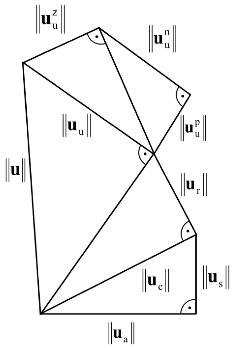
The determined components of voltage are orthogonal, so there is a relationship between the RMS values that can be presented mathematically and graphically (Figure 2):
u 2 = u a 2 + u s 2 + u r 2 + u u 2 ,
Thus, the RMS value of the unbalanced component of the voltage is:
u u = u 2 u a 2 u s 2 u r 2 .
The supply voltage has been decomposed into components describing the physical properties of the circuit analogously to the CPC theory according to the relationship:
u = u a + u s + u r + u u , where u u = u u p + u u n + u u z .
The power decomposition corresponds to the voltage decomposition (33), i.e., the apparent power S is presented as the resultant of active power P, reactive power Qi, scattered power Dsi, and unbalanced power Dui.
S 2 = P 2 + Q i 2 + D si 2 + D ui 2 .
The unbalanced power in a four-wire system is additionally interpreted as the resultant of three symmetrical powers:
D ui 2 = D ui p 2 + D ui n 2 + D ui z 2 ,
whose values are determined from:
D u i = u u · i ,   D u i p = u u p · i ,   D u i n = u u n · i ,   D u i z = u u z · i .
The reactive Qi, scattered Dsi, and unbalanced power Dui were defined for voltage decomposition into individual components. The values of these powers are different from the values determined in the CPC theory:
Q i Q , D si D s , D ui D u .
The determined voltage components can be presented graphically (Figure 3).
The physical components of the voltage are related to the characteristic physical phenomena that can be dimensioned thanks to measurements at the load terminals. It should be emphasized here that these components do not exist physically—they are only the result of mathematical decomposition. So, they are more mathematical than physical quantities.

3. Numerical Illustration

The inductive load (Figure 4) was connected to a symmetrical three-phase source with parameters u R = 2 · e 230 e j ω 1 t + 10 e j 5 ω 1 t   V , ω1 = 2π50 rad/s. The circuit topology and numerical values were adopted in accordance with the calculation example presented in [36].
This receiver can be described as follows (Table 1):
Active power is taken only in one phase and it is equal:
P = P R = n e Z ¯ R n · I R n 2 = 26454   W .
The current flows only in phase R, so the value of the three-phase current vector is:
i = n i n 2 = n I R n 2 = 162.646   A .
Thus, according to (7), the value of the equivalent resistance is:
R e = P i 2 = 1   Ω
and this is consistent with the value of the equivalent resistance determined in a single-phase circuit.
The RMS values of the individual three-phase voltage components are equal to:
  • The three-phase active voltage physical components (10).
    u a = P i = 162.646   V .
  • The scattered component us in this example is equal to zero because, according to (12), there is no dispersion of the resistance Re(n) around the equivalent resistance Re for all harmonics and all phases.
  • The three-phase reactive voltage physical components (16):
    u r = n X e n 2 i n 2 = 162.930   V .
  • The three-phase unbalanced voltage physical components (32):
    u u = u 2 u a 2 u s 2 u r 2 = 398.748 2 162.646 2 0 162.930 2 = 325.576   V .
In this case, the non-zero value of the unbalanced voltage results from the lack of load symmetry and means that u u R = 0   V ,
u u S = u S = 230 2 + 10 2 = 230.217   V , u u T = u T = 230 2 + 10 2 = 230.217   V .
This is due to Kirchhoff’s voltage law, which in this case means that the entire phase’s voltage uS and uT translates into the value of uuS and uuT. From (24), we get:
u u z = 153.478   V , u u p = u u n = 76.739   V .
The values of power are, respectively:
  • P = 26454   W ,
  • Q i = n X e n 2 i n 4 = 26450   var ,
  • D si = 0   VA ,
  • D u i p = u u p · i = 12481   VA ,
  • D u i n = u u n · i = 12481   VA ,
  • D u i z = u u z · i = 24963   VA ,
  • D u i = u u · i = 52954   VA .
According to (35), the correctness of power determination can be checked:
S = P 2 + Q i 2 + D si 2 + D ui 2 = 64854   VA = u · i
Comparing the obtained results with the values determined in [36], in which the CPC distribution was made, one can conclude the equality of active powers and the inequality of other powers, which was noted in (37).

4. The Concept of Compensation of Voltage Components

The classic method of compensation, consisting in the parallel connection of the reactive compensator with the load, makes it possible to improve the power factor λ to unity only when the scattered power Ds is zero.
Reduction in the scattered power in a three-phase system is possible only by connecting a reactive compensator in series with the load (Figure 5). Therefore, the decomposition into voltage components should be carried out and the power Dsi should be zeroed. When the load and the compensator are connected in series, the reactive power Qi is also reduced.
Adding a two-wire series to a current circuit changes the voltage supplying the receiver by the voltage drop on this compensator. Therefore, this compensation method requires control of the load supply voltage in each phase individually.
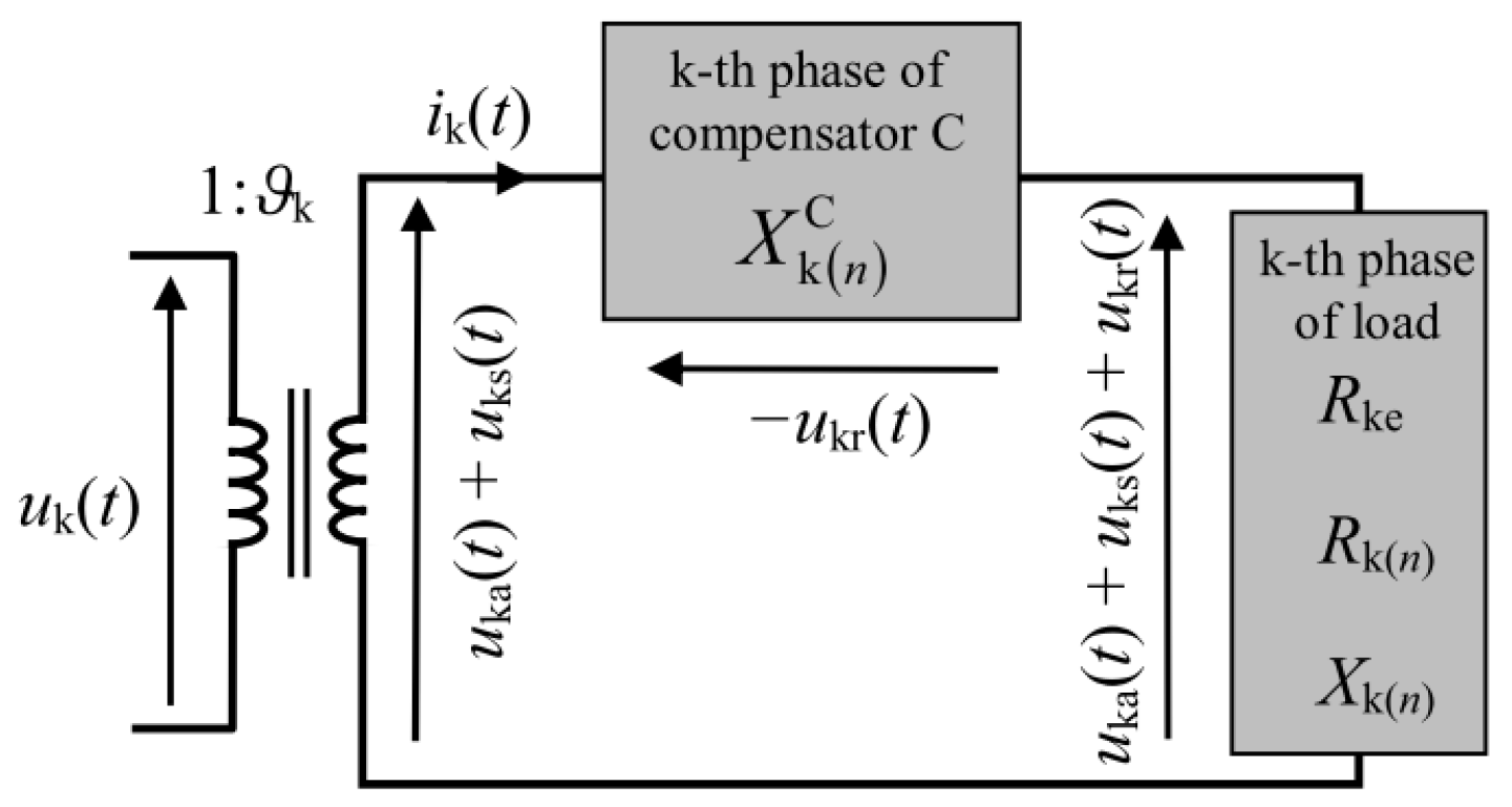
The use of an ideal compensator, i.e., one that is characterized by zero resistance and non-zero reactance X k n C , when connected in series with a load with impedance Z ¯ k n = R k n + j X k n where k = R, S, T, causes a change in the load impedance of the source (Figure 6). In general, for all phases, we can write:
Z ¯ k n = R k n + j X k n + X k n C .
After compensation, the resistance Rk(n) and the equivalent resistance Re do not change. Assuming that the supply current will not change, the active power P and the scattered power Dsi will not change. Only the reactive voltage will change to the value:
u kr = 2 e n j X k n C + X k n · I ¯ k n e j n ω 1 t
The reactive component of voltage u kr reaches zero when the series compensator in each k-th phase, for each n-th harmonic, leads to the equality:
X k n C + X k n = 0 .
This type of compensation causes the source voltages to resonate with the load. The resonance, meaning the zeroing of the reactive component of voltage ukr, causes an increase in the value of the current flowing through the load, i.e., also an increase in the active power P.
Maintaining the same energy parameters, after compensation as before, requires the use of a transformer stepping down the supply voltage, the ratio of which is:
ϑ k = u k t u k t = u ka t 2 + u ks t 2 u ka t 2 + u ks t 2 + u kr t 2
When the non-linear nature of the transformer is neglected, the scattered component will also be zero, as assumed for the load, i.e., Dsi = 0. In this case, the total power compensation of Qi means that the power factor λ becomes equal to 1.
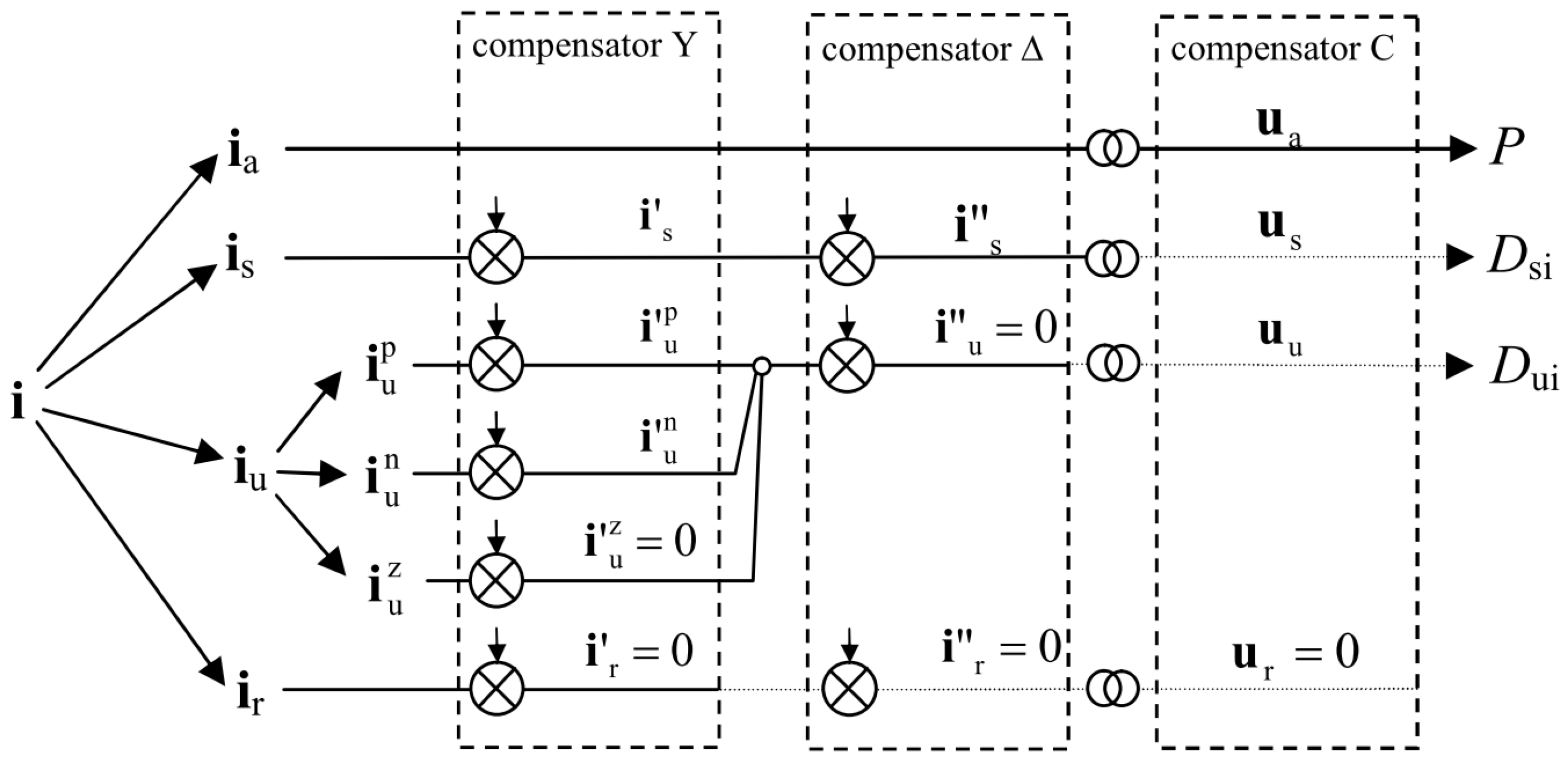
Each stage of the compensator has different functions (Figure 7). Individual stages of the compensator affect the appropriate components. To compensate for the scattered component is, the operating point of the system should be changed by adding a series impedance to each phase together with a transformer with an appropriate ratio. The remaining components are compensated with two compensators, Y and Δ [36].
The basic condition for complete compensation is the lack of voltage components in the compensator C: scattered us and unbalanced uu.

5. Evaluation of the Compensation Method Using the VPC Power Theory

First of all, it is necessary to present the limitations that the VPC method brings to the considerations.
(a)
Unidirectional energy flow in phases.
Equation (4) imposes unidirectionality for the energy flow in each phase. Changing the direction of energy flow in one of the phases relative to the others results in the inability to determine the VPC decomposition.
(b)
Modeling distributed and renewable energies.
If the load will be an electricity producer, the equations should be modified. The presented equations do not take into account voltage sources on the receiving side. To be able to use the VPC power theory in the case of distributed and renewable energy, equations must be developed that take into account voltage sources on the receiving side.
(c)
The use of VPC theory for large distribution networks.
The description of large distribution networks in accordance with the presented VPC theory is possible, but one must remember the remarks presented in items a and b. VPC decomposition for a large passive distribution network is possible; however, the idea of reactive compensation in series connection in phase lines with the flow of large currents is economically unprofitable. The presence of large banks of variable capacitances and inductances may turn out to be less advantageous in terms of economic and weight–size parameters compared to a synchronous electric machine compensator.
(d)
Analysis of the profitability of compensation in a series connection.
In the case of compensation for high currents, the profitability of using reactance in a series connection in individual phases has been discussed in the previous items. In the case of low power, the use of series compensation may be considered. A qualitative comparison of compensation methods is only possible when analyzing a specific circuit. For example, for a single-phase receiver connected to a three-phase network according to the example presented in [36]:
  • Before compensation, the power factor is λ = 0.4079.
  • The classical method of compensation consisting only of affecting the reactive component ir = 0 improves the power factor to the value λ = 0.4468.
  • As a result of the operation of the two-stage compensator presented in [36], it is possible to zero the unbalanced component iu = 0, which causes the power factor to reach the value λ = 0.9992.
  • Only zeroing the scattered component is = 0 gives the power factor λ = 1, but this is only possible as a result of the cooperation of the series compensator.
The last stage of compensation provides the least benefit and is the most expensive element to perform. In the example discussed, there is no economic indication of the profitability of using a series compensator, but thanks to theoretical considerations, it is possible to answer the following question: is total compensation possible in a three-phase, four-wire circuit?

6. Conclusions

Connecting in series the compensator with the load affects the value of the current and voltage supplying the receiver, so this method requires the use of a regulated power source. In the case of an asymmetrical system, the regulation should be carried out individually in each phase. Such a solution is rather far from the standards of modern power circuits, but such a compensation method is the only way to reduce the scattered component.
The greatest value of this study is the presentation of the concept of decomposition into Voltages’ Physical Components (VPC) as an alternative to the commonly known method of decomposition into Currents’ Physical Components (CPC). Moreover, using the VPC method, it is possible to theorize about full compensation in three-phase circuits, i.e., one in which the power factor λ is equal to one. The authors are aware that the use of the VPC theory for power compensation in power systems has little practical application; however, it enables theoretical analyses and gives alternative solutions in electrical circuits.

Author Contributions

Conceptualization, K.Z.; methodology, K.Z.; validation, S.D.; formal analysis, K.Z.; investigation, K.Z.; resources, K.Z. and S.D.; data curation, K.Z.; writing—original draft preparation, K.Z.; writing—review and editing, K.Z.; visualization, K.Z.; supervision, K.Z.; project administration, K.Z. All authors have read and agreed to the published version of the manuscript.

Funding

This research received no external funding.

Data Availability Statement

Data are contained within the article.

Conflicts of Interest

The authors declare no conflict of interest.

Nomenclature

Symbols
β(n)generalized complex rotation coefficient
Duiunbalanced power, VA
Dsiscattered power, VA
ivector of instantaneous currents in a three-phase system, A
Ivector of complex currents in a three-phase system, A
iR, iS, iTinstantaneous values of line currents, A
λpower factor
mnumber of active phases
Pactive power, W
Qireactive power, var
Reequivalent resistance, Ω
Sapparent power, VA
ttime, s
uvector of instantaneous voltages in a three-phase system, V
Uvector of complex voltages in a three-phase system, V
uR, uS, uTinstantaneous voltage values relative to the virtual star point, V
uaactive component of voltage—three-phase vector, V
usscattered component of voltage—three-phase vector, V
urreactive component of voltage—three-phase vector, V
uuunbalanced component of voltage—three-phase vector, V
ω1basic pulsation, rad/s
Xreceiver reactance, Ω
Xeequivalent reactance, Ω
Zimpedance of the receiver, Ω
Zeequivalent impedance, Ω
Zuunbalanced impedance, Ω
ϑtransformer ratio
Subscripts, superscripts
R,S,T,Nphase and neutral wires
nharmonic number
kphase number
p, n, zpositive, negative, zero sequence
Ccompensator parameters
Acronyms
CPCCurrents’ Physical Components
VPCVoltages’ Physical Components

References

  1. Zajkowski, K. Settlement of reactive power compensation in the light of white certificates. In E3S Web Conferences; EDP Sciences: Les Ulis, France, 2017; Volume 19. [Google Scholar] [CrossRef]
  2. Zajkowski, K.; Rusica, I. Comparison of electric powers measured with digital devices relative to powers associated with distinctive physical phenomena. IOP Conf. Ser. Mater. Sci. Eng. 2019, 564, 012133. [Google Scholar] [CrossRef]
  3. Zajkowski, K.; Duer, S.; Paś, J.; Pokorádi, L. Cooperation of a Non-Linear Receiver with a Three-Phase Power Grid. Energies 2023, 16, 1418. [Google Scholar] [CrossRef]
  4. Ginn, H.; Chen, G. Switching compensator control strategy based on CPC power theory. In Proceedings of the International School on Nonsinusoidal Currents and Compensation, Łagów, Poland, 10–13 June 2008. [Google Scholar]
  5. Czarnecki, L.S. Reactive and unbalanced currents compensation in three-phase circuits under nonsinusoidal conditions. IEEE Trans. Instrum. Meas. 1989, 38, 754–759. [Google Scholar] [CrossRef]
  6. Czarnecki, L.S.; Haley, P.M. Unbalanced Power in Four-Wire Systems and Its Reactive Compensation. IEEE Trans. Power Deliv. 2015, 30, 53–63. [Google Scholar] [CrossRef]
  7. Czarnecki, L.S.; Almousa, M. Adaptive balancing by reactive compensators of three-phase linear loads supplied by nonsinusoidal voltage from four-wire lines. Am. J. Electr. Power Energy Syst. 2021, 10, 32–42. [Google Scholar] [CrossRef]
  8. Czarnecki, L.S.; Hsu, S.M. Thyristor controlled susceptances for balancing compensators operated under nonsinusoidal conditions. IEE Proc.-Electr. Power Appl. 1994, 141, 177–185. [Google Scholar] [CrossRef]
  9. Shepherd, W.; Zakikhani, P. Suggested definition of reactive power for nonsinusoidal systems. In Proceedings of the Institution of Electrical Engineers; IET Digital Library: Stevenage, UK, 1972; Volume 119, pp. 1361–1362. [Google Scholar]
  10. Jeltsema, D.; Woude, J. Currents’ Physical Components (CPC) in the time-domain: Single-phase systems. In Proceedings of the 2014 European Control Conference (ECC), Strasbourg, France, 24–27 June 2014. [Google Scholar]
  11. Czarnecki, L.S. Currents’ Physical Components (CPC) in systems with semi-periodic voltages and currents. In Proceedings of the International School on Nonsinusoidal Currents and Compensation (ISNCC), Łagów, Poland, 15–18 June 2015. [Google Scholar]
  12. Czarnecki, L.S.; Toups, T.N. Working and Reflected Active Powers of Three-Phase Loads. In Proceedings of the 12th International School on Nonsinusoidal Currents and Compensation (ISNCC), Łagów, Poland, 15–18 June 2015. [Google Scholar]
  13. Bhattarai, P.D.; Czarnecki, L.S. Currents’ Physical Components (CPC) of the Supply Current of Unbalanced LTI Loads at Asymmetrical and Nonsinusoidal Voltage. Przegląd Elektrotechniczny 2017, 93, 30–35. [Google Scholar] [CrossRef]
  14. Grasso, F.; Luchetta, A.; Manetti, S.; Piccirilli, M.C.; Reatti, A.; Somma, M.; Cenghialta, F.; D’Antuono, E. Improvement of Power Flow Analysis based on Currents’ Physical Component (CPC) Theory, Circuits and Systems (ISCAS). In Proceedings of the IEEE International Symposium on Circuits and Systems (ISCAS), Florence, Italy, 27–30 May 2018; pp. 1–5. [Google Scholar]
  15. Izaguirre, A.R.; Macias, M.E.; Martell, F. Accurate CPC Power Analysis under Extreme EAF’s Distortion Conditions. In Proceedings of the 12th International School on Nonsinusoidal Currents and Compensation (ISNCC), Łagów, Poland, 15–18 June 2015. [Google Scholar]
  16. Martell, F.; Izaguirre, A.; Macías, M. CPC power theory for analysis of Arc Furnaces. In Proceedings of the International School on Nonsinusoidal Currents and Compensation (ISNCC), Łagów, Poland, 15–18 June 2015. [Google Scholar]
  17. Busarello, T.D.C.; Péres, A.; Mortezaei, A.; Simões, M.G. Application of the current decomposition of the Conservative Power Theory in Distributed Energy Resources. In Proceedings of the 12th IEEE International Conference on Industry Applications (INDUSCON), Curitiba, Brazil, 20–23 November 2016. [Google Scholar]
  18. Czarnecki, L.S. Degradation of the Energy Transfer Effectiveness Described in Terms of Currents’ Physical Components (CPC)-based Power Theory. In Proceedings of the 2017 International Symposium on Computer Science and Intelligent Controls (ISCSIC), Budapest, Hungary, 20–22 October 2017. [Google Scholar]
  19. Busarello, T.D.C.; Mortezaei, A.; Péres, A.; Simões, M.G. Application of the Conservative Power Theory Current Decomposition in a Load Power-Sharing Strategy Among Distributed Energy Resources. IEEE Trans. Ind. Appl. 2018, 54, 3771–3781. [Google Scholar] [CrossRef]
  20. Popescu, M.; Bitoleanu, A.; Suru, V. Currents’ physical components theory implementation in shunt active power filtering for unbalanced loads. In Proceedings of the International School on Nonsinusoidal Currents and Compensation (ISNCC), Zielona Góra, Poland, 20–21 June 2013. [Google Scholar]
  21. Borges, A.M.; Alves, S. Currents’ physical components (CPC): Case studies in single phase systems. In Proceedings of the 2018 Simposio Brasileiro de Sistemas Eletricos (SBSE), Niteroi, Brazil, 12–16 May 2018. [Google Scholar]
  22. Czarnecki, L.S.; Haley, P.M. Power Properties of Four-Wire Systems at Nonsinusoidal Supply Voltage. IEEE Trans. Power Deliv. 2016, 31, 513–521. [Google Scholar] [CrossRef]
  23. Mikulovic, J.; Sekara, T.; Skrbic, B. Currents’ physical component (CPC) power theory for three-phase four-wire systems. In Proceedings of the Mediterranean Conference on Power Generation, Transmission, Distribution and Energy Conversion, Belgrade, Serbia, 6–9 November 2016. [Google Scholar]
  24. Li, W.; Rahmani, B.; Liu, G. Expansion of Current Physical Components (CPC) to Three-Phase Four-Wire Systems under Non-Ideal Waveforms by the AUPQS. In Proceedings of the 2016 Sixth International Conference on Instrumentation & Measurement, Computer, Communication and Control, Los Alamitos, CA, USA, 21–23 July 2016. [Google Scholar]
  25. Czarnecki, L.S.; Almousa, M. Conversion of fixed-parameters compensator in four-wire system with nonsinusoidal voltage into adaptive compensator. Przegląd Elektrotechniczny 2021, 97, 1–6. [Google Scholar] [CrossRef]
  26. Czarnecki, L.S.; Almousa, M. Adaptive Compensation of Reactive, Unbalanced and DC Currents of AC Arc Furnaces. Przegląd Elektrotechniczny 2023, 99. [Google Scholar] [CrossRef]
  27. Smyczek, J.; Zajkowski, K. Simulation of overvoltages for switching off lagging load from mains. In Proceedings of the 2nd International Industrial Simulation Conference, Malaga, Spain, 7–9 June 2004; pp. 278–281. [Google Scholar]
  28. Siergiejczyk, M.; Pas, J.; Rosinski, A. Modeling of Process of Maintenance of Transport Systems Telematics with Regard to Electromagnetic Interferences. Tools Transp. Telemat. 2015, 531, 99–107. [Google Scholar]
  29. Zajkowski, K. An innovative hybrid insulation switch to enable/disable electrical loads without overvoltages. E3S Web Conf. 2017, 19, 01033. [Google Scholar] [CrossRef]
  30. Paś, J.; Rosiński, A.; Wisnios, M.; Stawowy, M. Assessing the Operation System of Fire Alarm Systems for Detection Line and Circuit Devices with Various Damage Intensities. Energies 2022, 15, 3066. [Google Scholar] [CrossRef]
  31. Czarnecki, L.S.; Bahattarai, P.D. A Method of Calculating LC Parameters of Balancing Compensators for AC Arc Furnaces. IEEE Trans. Power Deliv. 2017, 32, 688–695. [Google Scholar] [CrossRef]
  32. Savant, V.; Kadrolkar, A.; Gupte, S. Bidirectional tie-line inverter based on instantaneous reactive power theory for microgrid applications. In Proceedings of the 2017 Second International Conference on Electrical, Computer and Communication Technologies (ICECCT), Coimbatore, India, 22–24 February 2017. [Google Scholar]
  33. Salim, C. Five-level series active power filter performances based on modified instantaneous reactive power theory for harmonic voltage disturbances compensation. In Proceedings of the 2017 5th International Conference on Electrical Engineering-Boumerdes (ICEE-B), Boumerdes, Algeria, 29–31 October 2017. [Google Scholar]
  34. Zajkowski, K. Reactive power compensation in a three-phase power supply system in an electric vehicle charging station. J. Mech. Energy Eng. 2018, 2, 75–84. [Google Scholar] [CrossRef]
  35. Zajkowski, K.; Rusica, I. The method of calculating LC parameters of balancing compensators in a three-phase four-wire circuit for an unbalanced linear receiver. IOP Conf. Ser. Mater. Sci. Eng. 2019, 564, 012134. [Google Scholar] [CrossRef]
  36. Zajkowski, K. Two-stage reactive compensation in a three-phase four-wire systems at nonsinusoidal periodic waveforms. Electr. Power Syst. Res. 2020, 184, 106296. [Google Scholar] [CrossRef]
  37. Haugan, T.S.; Tedeschi, E. Active power filtering under non-ideal voltage conditions using the conservative power theory. In Proceedings of the IEEE 13th Brazilian Power Electronics Conference and 1st Southern Power Electronics Conference (COBEP/SPEC), Fortaleza, Brazil, 29 November–2 December 2015. [Google Scholar]
  38. Janabi, A.; Wang, B. Hybrid matrix converter based on instantaneous reactive power theory. In Proceedings of the IECON 2015-41st Annual Conference of the IEEE Industrial Electronics Society, Yokohama, Japan, 9–12 November 2015. [Google Scholar]
  39. Rosa, R.B.; Vahedi, H.; Godoy, R.B.; Pinto, J.O.P.; Al-Haddad, K. Conservative Power Theory Used in NPC-Based Shunt Active Power Filter to Eliminate Electric Metro System Harmonics. In Proceedings of the 2015 IEEE Vehicle Power and Propulsion Conference (VPPC), Montreal, QC, Canada, 19–22 October 2015. [Google Scholar]
  40. Taher, S.A.; Alaee, M.H.; Dehghani, A.Z. Model predictive control of PV-based shunt active power filter in single phase low voltage grid using conservative power theory. In Proceedings of the 2017 8th Power Electronics, Drive Systems & Technologies Conference (PEDSTC), Mashhad, Iran, 14–16 February 2017. [Google Scholar]
  41. Alaee, M.H.; Taher, S.A.; Dehghani, A.Z. Improved performance of single-phase shunt active power filter by using conservative power theory and model predictive control. In Proceedings of the 2018 9th Annual Power Electronics, Drives Systems and Technologies Conference (PEDSTC), Tehran, Iran, 13–15 February 2018. [Google Scholar]
  42. Javadi, A.; Hamadi, A.; Al-Haddad, K. Three-phase power quality device tor weak Systems based on SRF and p-q theory controller. In Proceedings of the IECON 2015-41st Annual Conference of the IEEE Industrial Electronics Society, Yokohama, Japan, 9–12 November 2015. [Google Scholar]
  43. Kong, X.; Yuan, Y.; Huang, H.; Wang, Y. Overview of the instantaneous reactive power theory in three-phase systems. In Proceedings of the 5th International Conference on Electric Utility Deregulation and Restructuring and Power Technologies (DRPT), Changsha, China, 26–29 November 2015; pp. 2331–2336. [Google Scholar]
  44. Abdullah, A.; Biswal, G.R.; Roy, A.K. Modeling and control of hybrid power filter using p-q theory. In Proceedings of the 2016 IEEE 1st International Conference on Power Electronics, Intelligent Control and Energy Systems (ICPEICES), Delhi, India, 4–6 July 2016. [Google Scholar]
  45. Abbasi, M.; Tousi, B. Novel controllers based on instantaneous p-q power theory for transformerless SSSC and STATCOM. In Proceedings of the 2017 IEEE International Conference on Environment and Electrical Engineering and 2017 IEEE Industrial and Commercial Power Systems Europe (EEEIC/I&CPS Europe), Milan, Italy, 6–9 June 2017. [Google Scholar]
  46. Souza, W.A.; Liberado, E.V.; da Silva, L.C.P.; Paredes, H.K.M.; Marafão, F.P. Load analyser using conservative power theory. In Proceedings of the International School on Nonsinusoidal Currents and Compensation (ISNCC), Zielona Góra, Poland, 20–21 June 2013. [Google Scholar]
  47. Busarello, T.D.C.; Simões, M.G. Power quality enhancement by means of shunt compensators based on the conservative power theory. In Proceedings of the Clemson University Power Systems Conference (PSC), Clemson, SC, USA, 10–13 March 2015. [Google Scholar]
  48. Haugan, T.S.; Tedeschi, E. Reactive and harmonic compensation using the conservative power theory. In Proceedings of the Tenth International Conference on Ecological Vehicles and Renewable Energies (EVER), Monte Carlo, Monaco, 31 March–2 April 2015. [Google Scholar]
  49. Busarello, T.D.C.; Pomilio, J.A.; Simões, M.G. Passive Filter Aided by Shunt Compensators Based on the Conservative Power Theory. IEEE Trans. Ind. Appl. 2016, 52, 3340–3347. [Google Scholar] [CrossRef]
  50. Mortezaei, A.; Simões, M.; Savaghebi, M.; Guerrero, J.; Durra, A.A. Cooperative control of multi-master-slave islanded microgrid with power quality enhancement based on conservative power theory. In Proceedings of the 2017 IEEE Power & Energy Society General Meeting, Chicago, IL, USA, 16–20 July 2017. [Google Scholar]
  51. Oruganti, V.S.R.V.; Bubshait, A.S.; Dhanikonda, V.S.S.S.; Simões, M.G. Real-time control of hybrid active power filter using conservative power theory in industrial power system. IET Power Electron. 2017, 10, 196–207. [Google Scholar] [CrossRef]
  52. Monteiro, L.F.C.; Afonso, J.L.; Pinto, J.G.; Watanabe, E.H.; Aredes, M.; Akagi, H. Compensation algorithms based on the p-q and CPC theories for switching compensators in micro-grids. In Proceedings of the Brazilian Power Electronics Conference, Bonito-Mato Grosso do Sul, Brazil, 27 September–1 October 2009. [Google Scholar]
  53. Harirchi, F.; Simoes, M.G. Enhanced Instantaneous Power Theory Decomposition for Power Quality Smart Converter Applications. IEEE Trans. Power Electron. 2018, 33, 9344–9359. [Google Scholar] [CrossRef]
  54. Kumar, H.; Patra, J.; Yadav, A.; Pal, N. Power quality assessment and improvement of 3-phase 3-wire non-linear system using instantaneous power theory based DSTATCOM. In Proceedings of the 4th International Conference on Recent Advances in Information Technology (RAIT), Dhanbad, India, 15–17 March 2018. [Google Scholar]
  55. Busarello, T.D.C.; Pomilio, J.A. Synergistic operation of distributed compensators based on the conservative power theory. In Proceedings of the IEEE 13th Brazilian Power Electronics Conference and 1st Southern Power Electronics Conference, (COBEP/SPEC), Fortaleza, Brazil, 29 November–2 December 2015. [Google Scholar]
  56. Duer, S.; Zajkowski, K.; Harnicarova, M.; Charun, H.; Bernatowicz, D. Examination of multivalent diagnoses developed by a diagnostic program with an artificial neural network for devices in the electric hybrid power supply system “House on Water”. Energies 2021, 14, 2153. [Google Scholar] [CrossRef]
  57. Suproniuk, M.; Pas, J. Analysis of electrical energy consumption in a public utility buildings. Przegląd Elektrotechniczny 2019, 95, 97–100. [Google Scholar] [CrossRef]
  58. Wisnios, M.; Pas, J. The assessment of exploitation process of power for access control system. E3S Web Conf. 2017, 19, 01034. [Google Scholar] [CrossRef]
  59. Marcu, M.; Popescu, F.G.; Niculescu, T.; Pana, L.; Handra, A.D. Simulation of power active filter using instantaneous reactive power theory. In Proceedings of the 2014 16th International Conference on Harmonics and Quality of Power (ICHQP), Bucharest, Romania, 25–28 May 2014; pp. 581–585. [Google Scholar]
  60. Zajkowski, K.; Rusica, I.; Palkova, Z. The use of CPC theory for energy description of two nonlinear receivers. MATEC Web Conf. 2018, 178, 09008. [Google Scholar] [CrossRef]
  61. Moghaddam, F.K.; Farhangi, S. Improvement of the stand-alone DFIG performance feeding nonlinear and unbalanced loads using active and reactive power theory. In Proceedings of the 2015 IEEE Conference on Energy Conversion (CENCON), Johor Bahru, Malaysia, 19–20 October 2015; pp. 128–133. [Google Scholar]
  62. Hanzelka, Z. Blueprint for the combinatorial strategy in transactive energy-based control mechanism by using energy flexibility platform and interface. CIRED-Open Access Proc. J. 2017, 2017, 1597–1600. [Google Scholar]
  63. Lada, M.Y.; Mohamad, S.S.; Gani, J.A.M.; Nawawi, M.R.M.; Kim, G.C. Reduction of harmonic using single phase shunt active power filter based on instantaneous power theory for cascaded multilevel inverter. In Proceedings of the 2016 IEEE International Conference on Power and Energy (PECon), Melaka, Malaysia, 28–30 November 2016. [Google Scholar]
  64. Tobola, A.; Mikołajuk, K. Multiobjective Optimization Approach to the Active Power Filter Control. In Proceedings of the 17th International Conference Computational Problems of Electrical Engineering (CPEE), Sandomierz, Poland, 14–17 September 2016. [Google Scholar]
  65. Tobała, A.; Mikołajuk, K. Reference Signal Detection for Voltage Harmonic Damping in Three-Phase Systems. In Proceedings of the 18th International Conference on Computational Problems of Electrical Engineering (CPEE), Kutna Hora, Czech Republic, 11–13 September 2017. [Google Scholar]
  66. Zhu, L.; Chang, L.; Yan, J.; Li, F.; Yang, Y.; Su, X.; Wu, Z.; Cui, D. Research on shunt active power filter based on the improved instantaneous reactive power theory. In Proceedings of the 2015 Sixth International Conference on Intelligent Control and Information Processing (ICICIP), Wuhan, China, 26–28 November 2015; pp. 459–464. [Google Scholar]
  67. Hanzelka, Z.; Mondzik, A. Different LC power filter topologies-effectiveness of reducing voltage distortion. Renew. Energy Power Qual. J. 2016, 14, 322–327. [Google Scholar]
  68. Mboving, C.S.A.; Hanzelka, Z. Hybrid Power Active Filter-Effectiveness of Passive Filter on the Reduction of Voltage and Current Distortion. In Proceedings of the Electric Power Quality and Supply Reliability (PQ), Tallinn, Estonia, 29–31 August 2016. [Google Scholar]
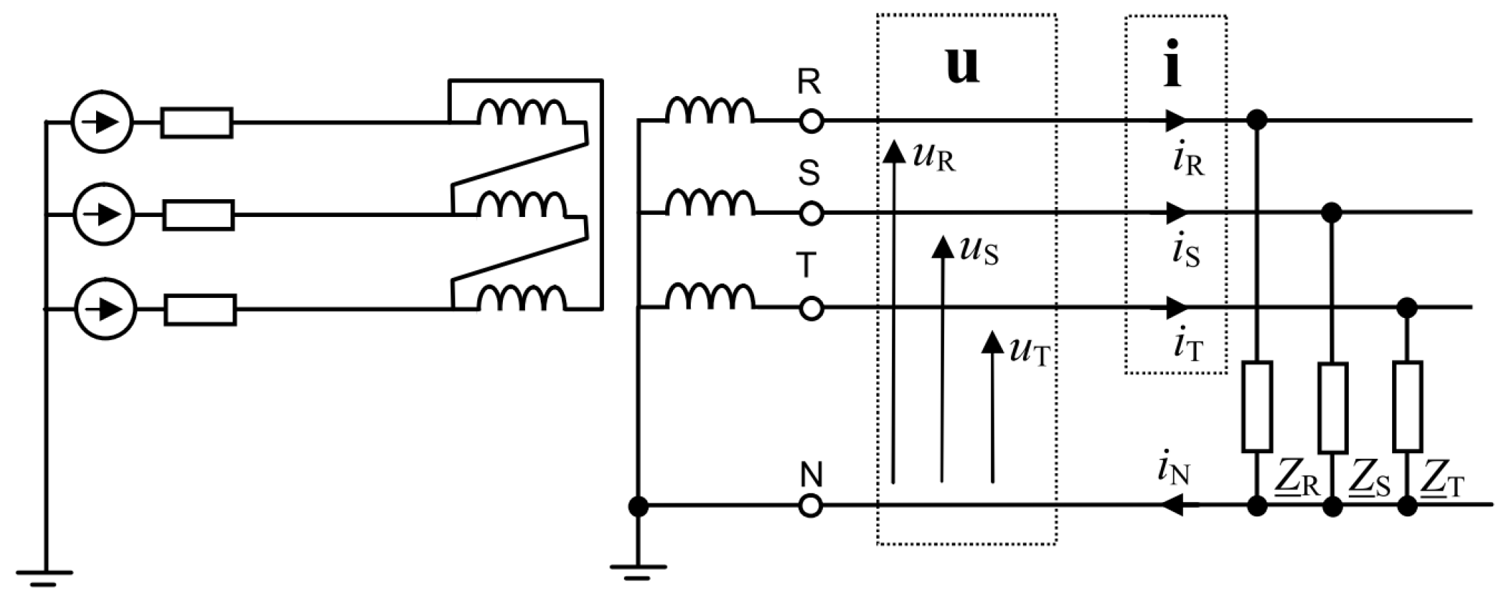
Figure 1. Three-phase load cooperating with a three-wire network.
Energies 16 07616 g001
Figure 2. Graphical interpretation of multidimensional three-phase vectors for the distribution of RMS voltage components with harmonic waveforms.
Energies 16 07616 g002
Figure 3. Graphical interpretation of voltage decomposition.
Energies 16 07616 g003
Figure 4. Circuit diagram for a calculation example.
Energies 16 07616 g004
Figure 5. Cooperation of a series compensator with a three-phase load.
Energies 16 07616 g005
Figure 6. System interpretation for one phase.
Energies 16 07616 g006
Figure 7. Compensation of individual components in a four-wire system.
Energies 16 07616 g007
Table 1. Impedances and current.
nZR(n) [Ω]Ze(n) [Ω]I(n) [A]
11 + j11 + j1115 − j115
51 + j51 + j5 5 / 13 j 25 / 13
Disclaimer/Publisher’s Note: The statements, opinions and data contained in all publications are solely those of the individual author(s) and contributor(s) and not of MDPI and/or the editor(s). MDPI and/or the editor(s) disclaim responsibility for any injury to people or property resulting from any ideas, methods, instructions or products referred to in the content.