Article

Large Eddy Simulation of Flow Characteristics around Cylinders with Crosswise and Streamwise Arrangements in Ocean Energy

1
Reactor Thermal-Hydraulic Laboratory, Reactor Engineering Technology Research Institute, China Institute of Atomic Energy, Beijing 102413, China
2
State Key Laboratory of Hydroscience and Engineering, Department of Energy and Power Engineering, Tsinghua University, Beijing 100084, China
3
State Grid Sichuan Electric Power Company, Chengdu 610041, China
*
Author to whom correspondence should be addressed.
Energies 2023, 16(22), 7605; https://doi.org/10.3390/en16227605
Submission received: 7 October 2023 / Revised: 7 November 2023 / Accepted: 10 November 2023 / Published: 16 November 2023
(This article belongs to the Section A3: Wind, Wave and Tidal Energy)

Abstract

:
The flow around cylinders is one of the most fundamental phenomena in extracting wave energy from ocean waves. Compared with flows around a single cylinder, the investigation of flows around multiple cylinders is still limited and requires further studies to reveal flow characteristics. To this end, large eddy simulations are conducted to investigate the flow around double cylinders with crosswise and streamwise arrangements. Systematic studies on the influence of the number of mesh cells, the first near-wall mesh size, and the transient time step are carried out to achieve accurate and efficient simulations. The drag coefficient, flow separation, and flow pattern for different arrangements under various cylinder spacings are analyzed according to simulation results. For the crosswise arrangement, the flow pattern switches from the single-body regime to the synchronized vortex-shedding regime as the spacing increases. For the streamwise arrangement, the flow pattern develops from the reattachment regime to the vortex-shedding regime as the spacing increases.

1. Introduction

The exploitation of ocean energy has raised a great deal of concern in recent years due to the burdens of fossil energy exhaustion and environmental pollution [1,2]. The extraction of ocean wave energy is widely recognized as a promising technology because it is adaptive to short-term energy storage. For wave energy conversion technologies, the periodic waves can result in the resonant motions of the body, especially with the existence of vortex-induced vibrations [3,4]. Then, the hydrokinetic energy of ocean waves can be converted into electricity through the vibrating bodies [5]. From this point of view, it is of great significance to investigate the vortex and vibration of flows around blunt bodies [6,7,8]. Among these studies, flow around cylinders [9,10] is one of the most common phenomena because of the extensive underlying mechanisms. It has attracted much attention [11], which provides effective guidance for the shape design to enhance lift and reduce drag [12].
The investigation starts from the flow around a single cylinder respective of different Reynolds numbers. In recent decades, owing to the rapid development of computation power, the technology of computational fluid dynamics (CFDs) has increasingly become a reliable tool for simulating flows around cylinders. Increasing computational power has also made it possible to conduct large eddy simulations (LESs) for turbulent flows [13,14]. Even for such simple geometries as a square cylinder or circular cylinder, complex flow phenomena will appear [15]. In order to improve the simulation accuracy of flows around cylinders, the influence of discretization scheme has been investigated by Breuer [16], and the central difference scheme shows better agreement with experimental results. The sub-grid scale (SGS) stress model is a significant aspect when conducting LESs. Studies by Lysenko et al. [17] indicate that the influence of the SGS model is almost negligible when near-wall regions are refined properly. Breuer [16], Kravchenko and Moin [18], and Ma et al. [19] investigated the influence of spanwise length on simulation results and found that they are almost independent of spanwise length when it is larger than π times the cylinder diameter. The existing studies have already established a framework to accurately simulate flows around a single cylinder by means of LESs [20,21,22].
Based on various studies on the flow around a single cylinder, researchers also have begun to pay attention to flows around multiple cylinders [23,24,25,26], which is closer to realistic conditions. When multiple cylinders are applied, the flow characteristics are influenced by different spacing and different arrangements, i.e., crosswise arrangement, streamwise arrangement, and staggered arrangement. Many experimental and numerical studies were conducted with various spacing [27,28,29]. Results show that there exists a critical value of non-dimensional spacing where the vortex-shedding regime will switch. For the crosswise arrangement, the vortex-shedding regime can be classified into three typical regimes: the single-body regime, biased-flow regime, and synchronized vortex-shedding regime [30,31,32]. The appearance of different regimes mainly depends on cylinder spacing. It is found that the vortex streets may influence each other to form a gap flow deflection under intermediate cylinder spacing, while becoming two symmetrical wake streets as cylinder spacing continues to increase [33]. Also, the interaction can become more significant when crosswise cylinders with different diameters are installed [34]. By comparison, the vortex-shedding regime for the streamwise arrangement is influenced by not only the cylinder spacing but also the Reynolds number. It can be classified into four regimes: the no-vortex-shedding regime, single-body regime, reattachment regime, and vortex-shedding regime [29]. Numerical simulations of flows around streamwise cylinders under moderate [35] and high [36] Reynolds numbers have been performed by means of LES. The drag and lift performance of the upstream and downstream cylinders are quite different under different Reynolds numbers [37].
Above all, it has been shown in the existing studies that the flow phenomena are even more complex in flows around multiple cylinders compared with a single cylinder. The flow characteristics of multiple cylinders are quite sensitive to both cylinder arrangements as well as the Reynolds number. However, according to the best of the authors’ knowledge, the numerical simulations on crosswise and streamwise arranged cylinders is relatively rare compared with such studies on a single cylinder. To this end, it is of great importance to investigate in detail the flow phenomena, i.e., drag performance, velocity profiles, and vorticity structures, in flows around multiple cylinders.
Therefore, large eddy simulations are conducted for flows around multiple cylinders with crosswise and streamwise arrangements in the present study. The influence of arrangement settings and cylinder spacing on flow characteristics is analyzed. The structure of the present paper is organized as follows. In Section 1, previous studies on flows around cylinders are reviewed. In Section 2, the present physical model and numerical methods are described, with detailed validation of the numerical settings. Then, the validated numerical methods are applied to double cylinders with crosswise and streamwise arrangements, and the simulation results are analyzed and discussed in Section 3. Finally, in Section 4, the main conclusion of the present study is summarized.

2. Numerical Methods

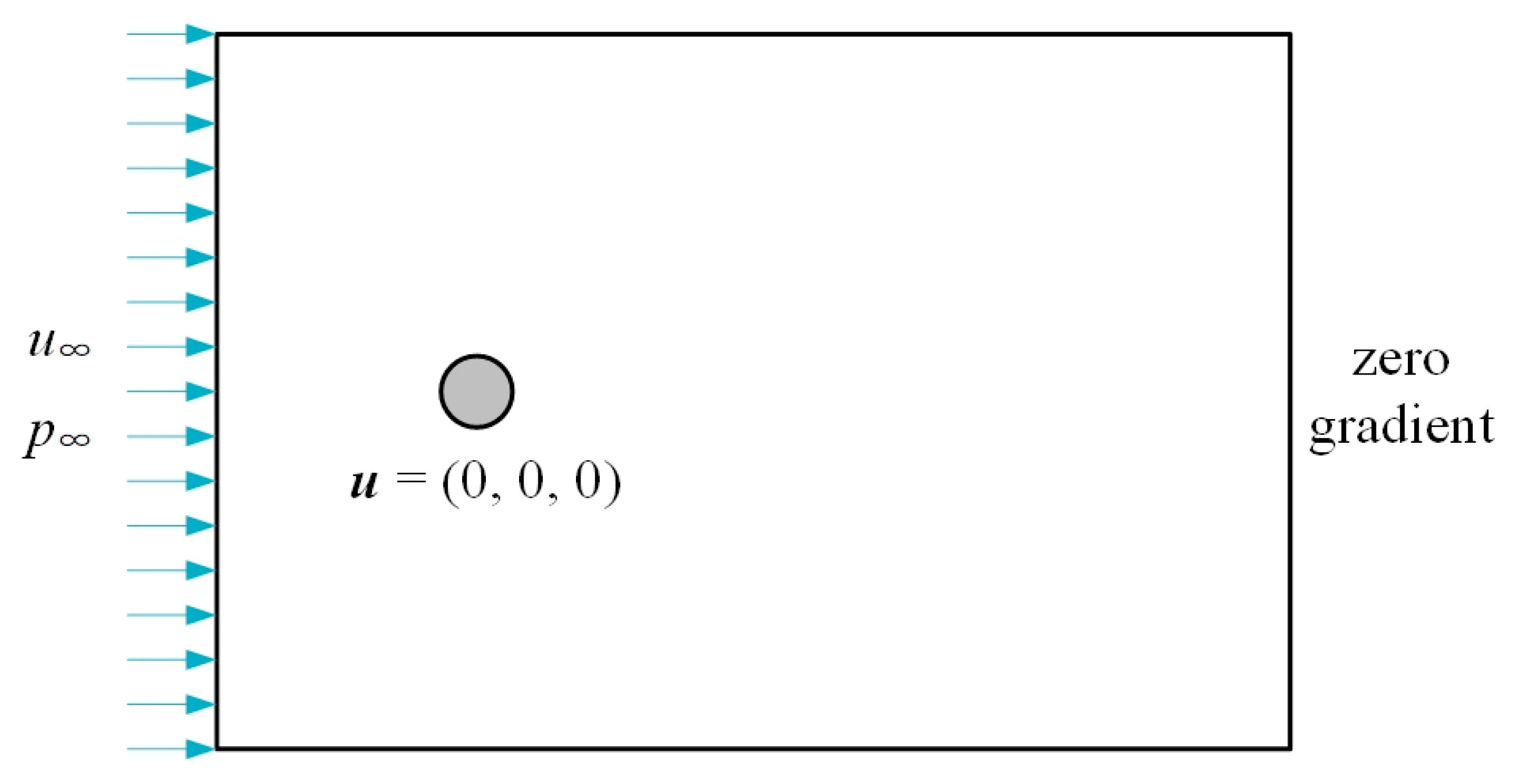
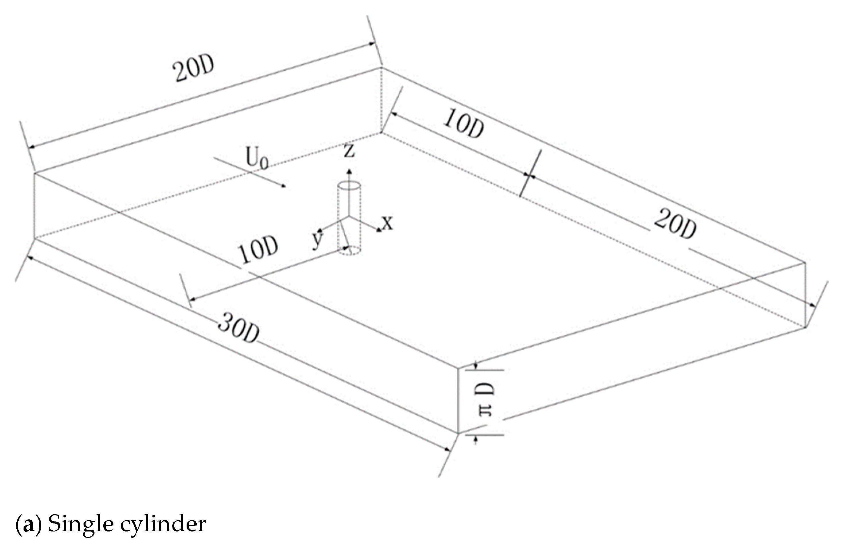
2.1. Physical Model and Computational Domain

As shown in Figure 1, the turbulent flow around the cylinder with a fixed inlet and zero gradient outlet is considered in the present study. Here, the fluid is regarded as incompressible with constant properties, i.e., density and viscosity.
As shown in Figure 2, flows around (a) a single circular cylinder, (b) crosswise cylinders, and (c) streamwise cylinders are investigated in the present study. The definition of the coordinate system is illustrated in Figure 2a, which also applies to the crosswise and streamwise cylinders. The inlet is set 10D upstream of the cylinder, and the outlet is set 20D downstream of the cylinder, where D denotes the diameter of the cylinder. The upper and lower boundaries are set 10D away from the cylinder, and the spanwise length is set as πD to eliminate its effect, according to previous studies [16]. The Reynolds number, Re = U0D/ν, is defined by the inflow velocity U0 and the cylinder diameter D, and kinematic viscosity ν is equal to 3900 in the present simulations [38]. For the crosswise arrangement, the distance between the cylinder centers perpendicular to the inflow direction T is regarded as the cylinder spacing, and it is normalized according to the cylinder diameter as T/D. For the streamwise arrangement, the distance between cylinder centers along the inflow direction L is regarded as the cylinder spacing, and it is also normalized according to the cylinder diameter as L/D.

2.2. Numerical Methods

Large eddy simulations of flows around cylinders are conducted by means of commercial CFD software ANSYS Fluent [39,40], and the Smagorinsky–Lilly SGS model is applied. The governing equations for large eddy simulations with the Smagorinsky–Lilly SGS model are listed as follows:
u ¯ j x j = 0 ,
u ¯ i t + u ¯ i u ¯ j x j = 1 ρ p ¯ x i + x j ν u ¯ j x j 1 ρ τ i j x j ,
where ui denotes velocity and the over-bar denotes filtered quantity; ρ, p, and ν stand for density, pressure, and kinetic viscosity, respectively; and τij is SGS turbulent stresses, which is calculated by:
τ i j = 2 μ t S ¯ i j + 1 3 δ i j τ k k ,
S ¯ i j = 1 2 u ¯ i x j + u ¯ j x i ,
μ t = ρ L s 2 2 S ¯ i j S ¯ i j ,
L s = m i n κ d , C s ,
where κ is the von Karman constant, d is the distance to the closest wall, Cs is the Smagorinsky constant, and Δ is the local grid size. The details for the numerical methods can be found in Ref. [41].
The pressure implicit with splitting of operators (PISOs) algorithm is used to couple velocity and pressure. Both skewness correction and neighbor correction are set as 1 in the present simulations. The bounded second order implicit time integration scheme is employed for temporal discretization. The fixed value of inflow velocity without turbulent fluctuations is given at the inlet, and the outflow boundary condition with zero gradient is set at the outlet. The no-slip boundary condition is set on the cylinder surface as well as the side boundaries in the y-direction. The periodic boundary conditions are employed for side boundaries in the z-direction. In the present simulations, turbulent perturbation is not introduced to the inflow velocity. The entrance length is set as 10 times the cylinder diameter, and it takes about 10 typical vortex-shedding cycles to become fully developed. The structured mesh is generated using commercial software ANSYS ICEM, and the mesh distributions around the single and double cylinders are displayed in Figure 3. The maximum value of y+ is kept as 1.5 for the grids so that wall function is not used in the present simulations.

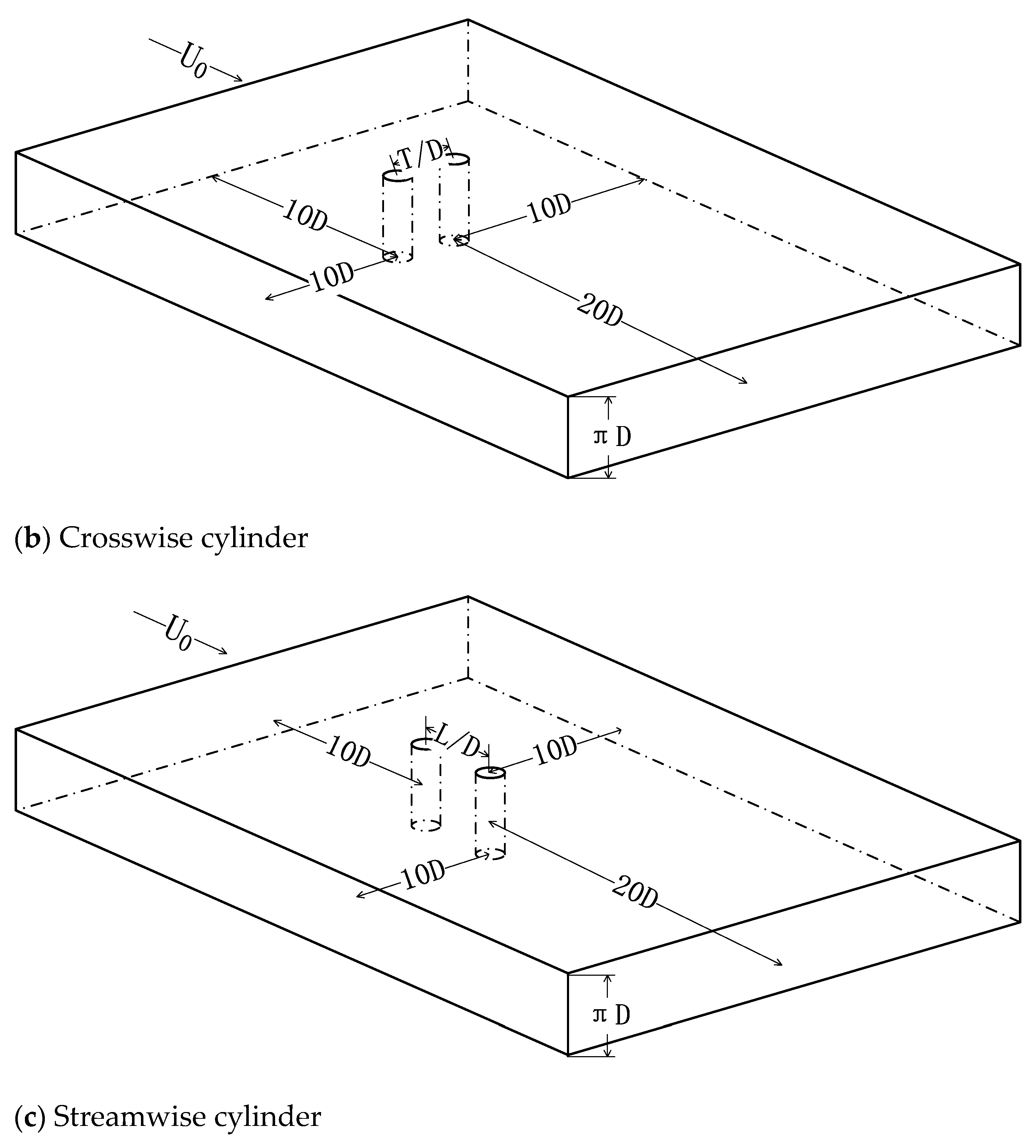
2.3. Grid Independence Tests

As indicated by previous numerical studies, the number of mesh cells, the cell size of the first near-wall layer, and the transient time steps will affect numerical results. Therefore, the influence of these factors is investigated in this section. For flows around a single cylinder, the drag coefficient and lift coefficient are defined to estimate its hydraulic performance as follows:
c D = F d 0.5 ρ U 2 A ,
c L = F l 0.5 ρ U 2 A ,
where Fd and Fl are the total drag and lift on the cylinder, respectively; ρ and U are the freestream density and velocity, respectively; and A is the projection area. Here, the experimental results of the time-averaged drag coefficient cD and Strouhal number St = fD/U by Ong and Wallace [11] are employed in the present study to validate the accuracy of the simulation results, where cD = 0.99 ± 0.05 and St = 0.215 ± 0.005 under Re = 3900. The Strouhal number is a dimensionless number that is widely used to describe oscillating flow mechanisms. In the present study, the vortex shedding frequency f is determined according to the fast Fourier transformation of the time evolution of the instantaneous lift coefficient within 40 typical vortex-shedding cycles. Figure 4 shows typical time evolution of drag coefficient and lift coefficient.
In the present study, a total of three sets of mesh are employed to validate the independence of the number of mesh cells. Here, the number of nodes on the radial direction (r), circumferential direction (θ), and spanwise direction (z) is gradually increased, and hence the corresponding total number of mesh cells rises from 0.78 million to 2.80 million. Table 1 lists mesh parameters and corresponding simulation results. It can be found that the simulation results hardly change when the number of mesh cells exceeds 1.82 million. Therefore, Mesh 2, with the medium number of mesh cells, is employed in the following simulations.
Then, keeping the total number of mesh cells constant, the cell size of the first near-wall layer is gradually reduced from 0.01 to 0.0001, and the corresponding value of y+ decreases from 8 to 0.5. The influence of the cell size of the first near-wall layer is summarized in Table 2. The simulation results of time-averaged drag coefficient are almost independent of its value, and hence Mesh 2-3, with y+ = 1.5, is employed in the following simulations. Here, the results are averaged with the time interval equal to the transient step within 40 typical vortex-shedding cycles.
Then, the value of the transient time step Δt is also a significant parameter for unsteady simulations. A total of three values of transient time step Δt are considered in the present simulations, and the simulation results are listed in Table 3. Both the time-averaged drag coefficient and Strouhal number are nearly unchanged as the transient time step reduces. Therefore, the value of Δt = 1 × 10⁻⁴ s is selected in the following studies to seek a balance between simulation accuracy and computation consumption.
So far, the mesh parameters and transient numerical settings for accurate and efficient simulations have been determined. According to the present numerical settings, the relative errors of time-averaged drag coefficient and Strouhal number compared with the existing experimental data are 1.88% and 0.14%, respectively, which validates the accuracy of the present numerical method. In the following analysis, these numerical settings will be applied to crosswise and streamwise cylinders.

3. Results and Discussion

3.1. Single Cylinder

Before the discussion of double cylinders, the simulation results of the single-cylinder case are analyzed. In this section, the Reynolds number is systematically increased from 1000 to 10,000 by increasing the inflow velocities, while the other numerical settings are kept the same. Table 4 summarizes the drag coefficient and Strouhal number at different Reynolds numbers. It can be found that, with the increase in the Reynolds number, the drag coefficient gradually reduces, while the Strouhal number increases and then decreases. Such variation trend shows good agreement with results reported in the existing literature [11].
The circumferential distribution of the mean pressure coefficient under different values of the Reynolds number are displayed in Figure 5 together with the schematic to illustrate the definition of the circumferential angle θ. The circumferential locations of the flow separation points are also listed in Table 5. As shown in Figure 5, the pressure coefficients at the windward side are almost the same under different Reynolds numbers. However, as the Reynold number increases, the flow separation point moves upstream, with a higher value of both the minimum pressure coefficient and the pressure recovery level at the leeward side. As a result, the drag coefficient also reduces with the increase in the Reynolds number.
Figure 6 displays the distribution of streamwise velocity along the y-direction at different downstream locations. Within the near wake regions (x/D = 1.06, 1.54, and 2.02), the distribution of streamwise velocity develops from a U-shape toward a V-shape. The minimum velocity at the centerline gradually reduces as the flow develops downstream. By comparison, in the downstream region further away from the cylinder (x/D = 6, 7, and 10), the streamwise velocity maintains a V-shaped distribution. However, the minimum velocity at the centerline gradually increases instead as the flow develops downstream. Comparing the velocity distribution at different Reynolds numbers, it can be found that the minimum velocity at the centerline increases and then decreases with the increase in the Reynolds number.

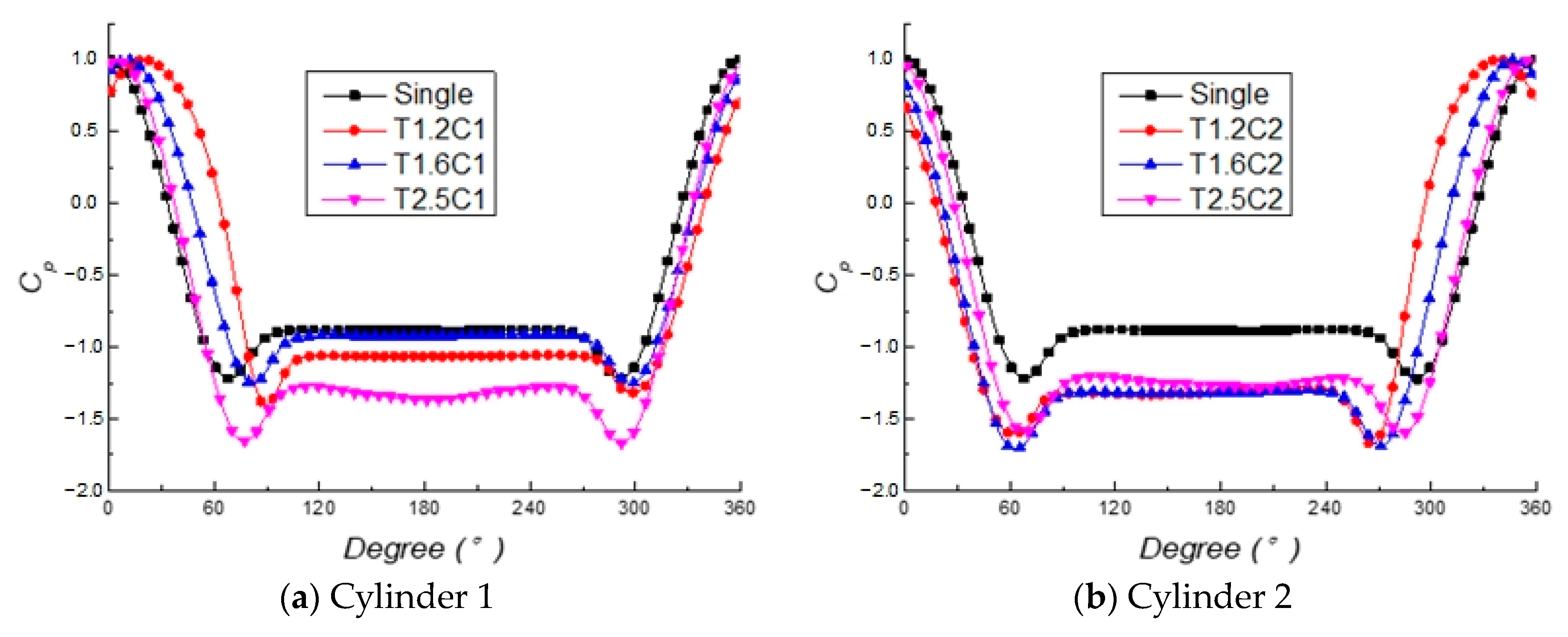
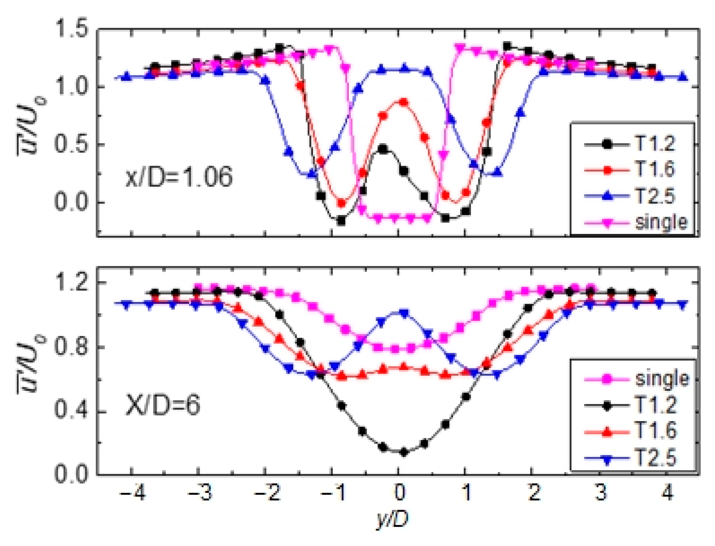
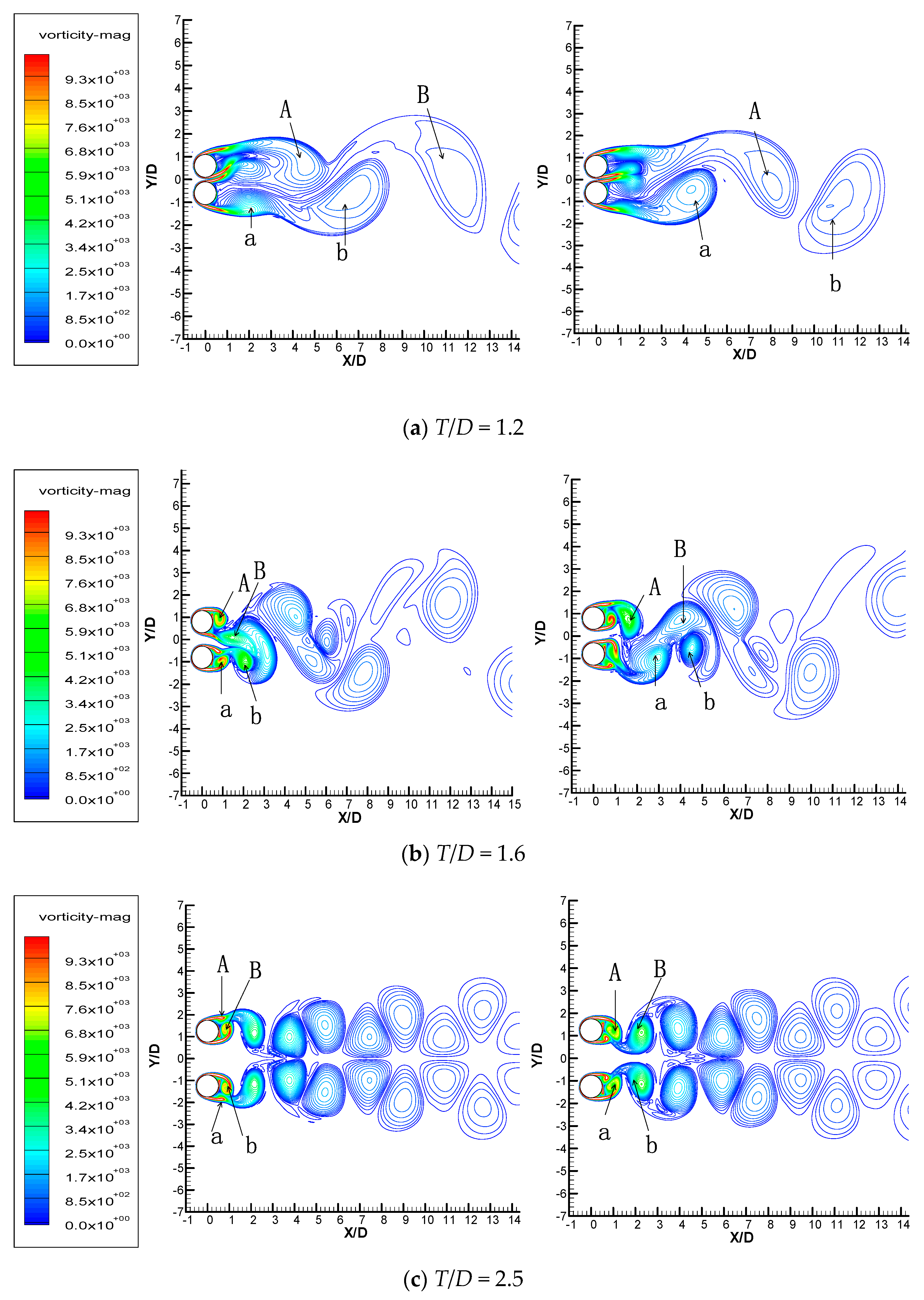
3.2. Crosswise Cylinders

For two cylinders with a crosswise arrangement, the following equivalent drag coefficient is defined as follows:
c D , s c D , 0 = c D , s 1 + c D , s 2 2 c D , 0 ,
where cD,s, cD,0, cD,s1, and cD,s2 denote the drag coefficient for the crosswise two cylinders, the single cylinder, the first cylinder in the crosswise arrangement, and the second cylinder in the crosswise arrangement, respectively. The equivalent drag coefficient for two cylinders is defined so that the drag performance of a two-cylinder system can be compared with the single cylinder directly. A total of three cases with different cylinder spacing are considered in the present study, i.e., T/D = 1.2, 1.6, and 2.5. Table 6 lists the hydrodynamic performances of the crosswise cylinders with different cylinder spacing. As shown in Table 6, the drag coefficient of crosswise cylinders is always higher than that of the single cylinder. Among the crosswise cylinders with different cylinder spacings, as the cylinder spacing increases, the drag coefficient decreases and then increases, while the Strouhal number gradually increases.
Figure 7 displays the circumferential distribution of pressure coefficient cp = (pp)/(0.5ρU2) in each cylinder for the crosswise arrangement. For the single-cylinder case, due to the absence of the influence of other cylinders, the near-wall shear wall in both sides can develop fully and freely and finally separates on the leeward side. As a result, an almost symmetrical distribution appears along the streamwise direction. By comparison, an asymmetrical distribution of pressure coefficients can be observed in each cylinder in the crosswise arrangement due to the wake interactions with each other. The location with maximum pressure coefficient, which corresponds to the stagnation point, is located on the cylinder directly in front of the incoming flow for the single-cylinder case. However, the stagnation point is then biased toward the side with the spacing for both cylinders in the crosswise arrangement.
In order to quantitatively compare the flow separation of different cases, the stagnation point θsta, the separation point on the spacing side θses, and the separation point on the other side θseo on each cylinder are calculated and summarized in Table 7. As the cylinder spacing increases, the deviation of the stagnation point gradually decreases, which indicates less interaction between the cylinders. As for the flow separation point, with the increase in cylinder spacing, for cylinder 1, the one at the spacing side moves downstream while the one at the outer side moves upstream. By comparison, for the other cylinder, the flow separation point at the spacing side moves upstream while the one at the outer side moves downstream. The difference between flow separation points on the spacing and outer sides |θsesθseo| represents the wake width. It can be seen that the wake width of cylinder 1 is always higher than that of cylinder 2. This phenomenon indicates that in the crosswise arrangement of two cylinders, one plays a more significant role than the other.
Figure 8 illustrates the distribution of the mean streamwise velocity at two downstream locations (x/D = 1.06, 6.00) for the single cylinder and crosswise cylinders. At the downstream location very close to the wake region, the velocity downstream of the crosswise cylinders shows a W-shaped distribution, while the single cylinder has a V-shaped distribution. When it comes to the wake region slightly away from the cylinder, the velocity for crosswise cylinders with small spacing (T/D = 1.2) tends to show a V-shaped distribution, which is similar to that for the single cylinder. However, the W-shaped distribution of velocity still appears in the larger spacing (T/D = 1.6 and 2.5). It is indicated that the flow patterns for the crosswise cylinders with small spacing of T/D = 1.2 belong to the single-body regime [30].
Figure 9 shows the contour distribution of vorticity around crosswise cylinders at different cylinder spacings at (left) t = t0 and (right) t = t0 + 5/6T, where T stands for the vortex shedding period. The vortex induced from the upper cylinder is denoted with capital letters (A and B), while the vortex induced from the lower cylinder is denoted with lowercase letters (a and b). At the smallest cylinder spacing of T/D = 1.2, because of the interaction of shear layers in the quite small spacing, the vortex at the spacing side induced from each cylinder is influenced by the other and quickly suppressed. Therefore, only the vortex at the outer side of each cylinder can shed from the cylinder and then form the so-called “single-body regime”, which is quite similar to the pattern of flow around a single cylinder. At the moderate cylinder spacing of T/D = 1.6, because of the weaker interaction of the shear layers, the vortex induced at the spacing side can also shed from the cylinder. Therefore, in the middle of the vortex band formed by the shedding of the outer sides of the two cylinders, a new vortex band is created, where the shedding vortex is generated alternately by the spacing side of the two cylinders. As the cylinder spacing further increases to T/D = 2.5, at this point the interaction of shear layers in the spacing is already very weak, so that the vortex shedding structures of the two cylinders are almost completely independent of each other. According to the above discussion, it can be concluded that the interaction of two crosswise cylinders will suppress vortex formation at the spacing side when the cylinder spacing is small.

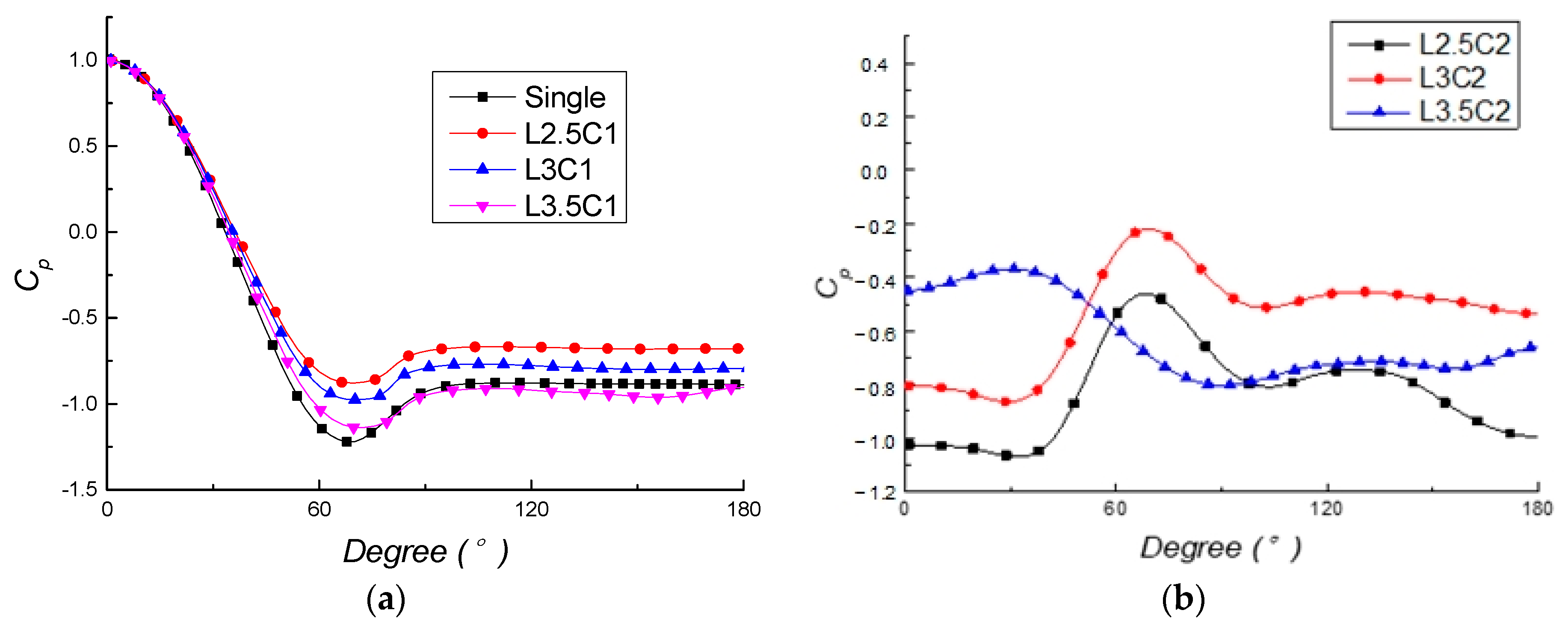
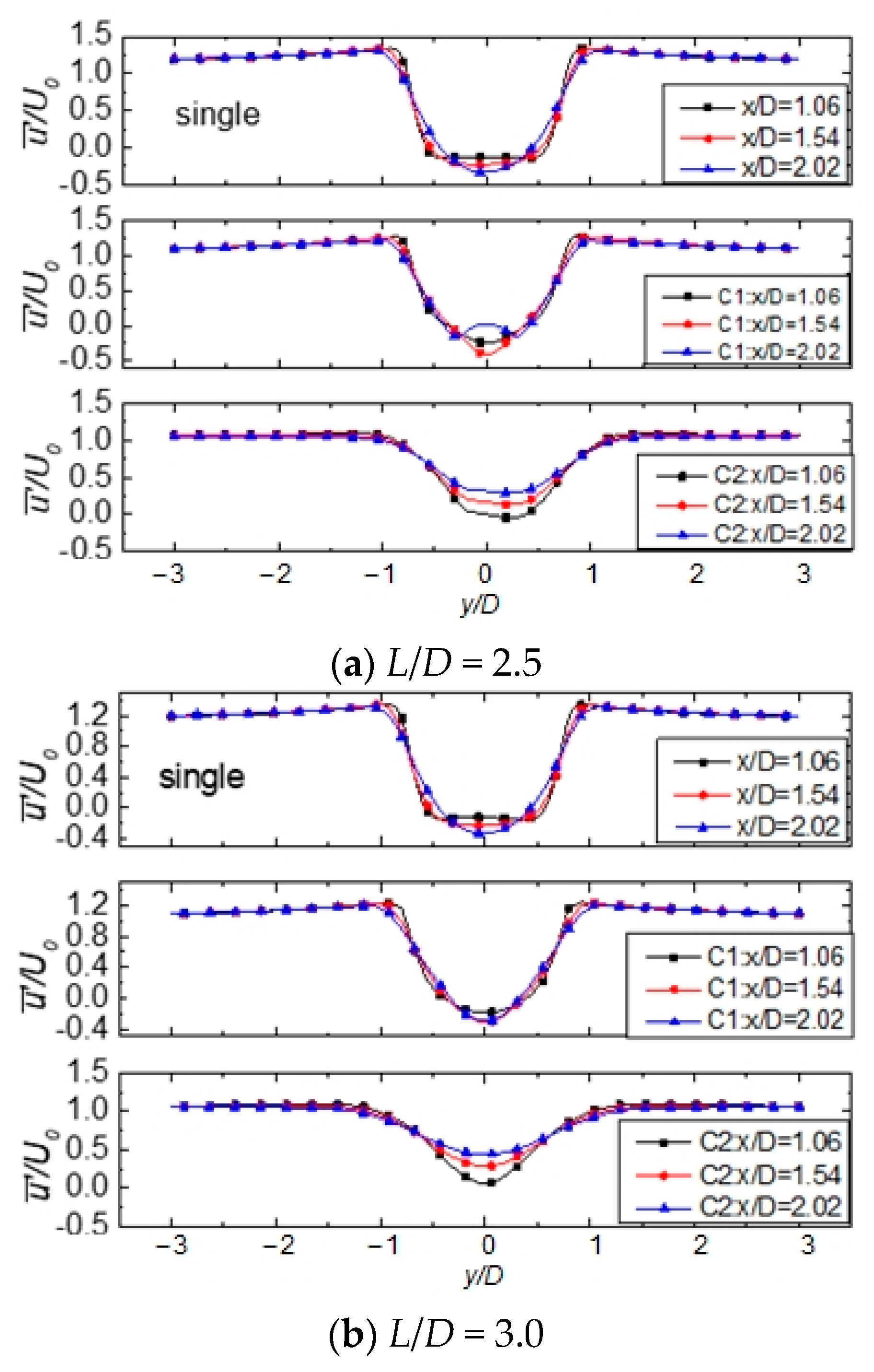
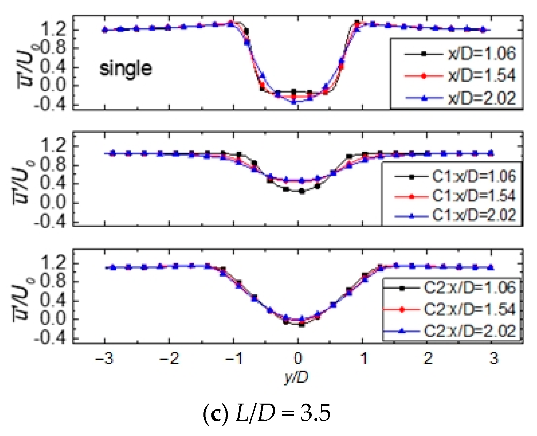
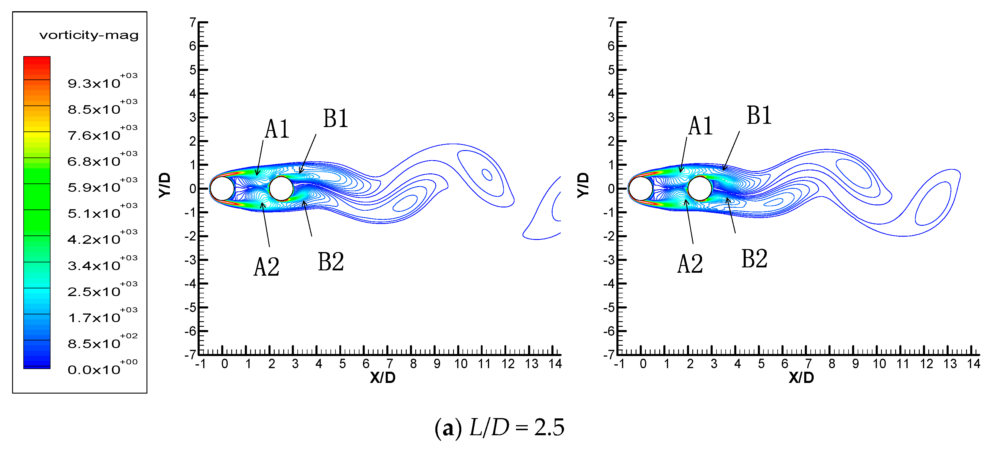
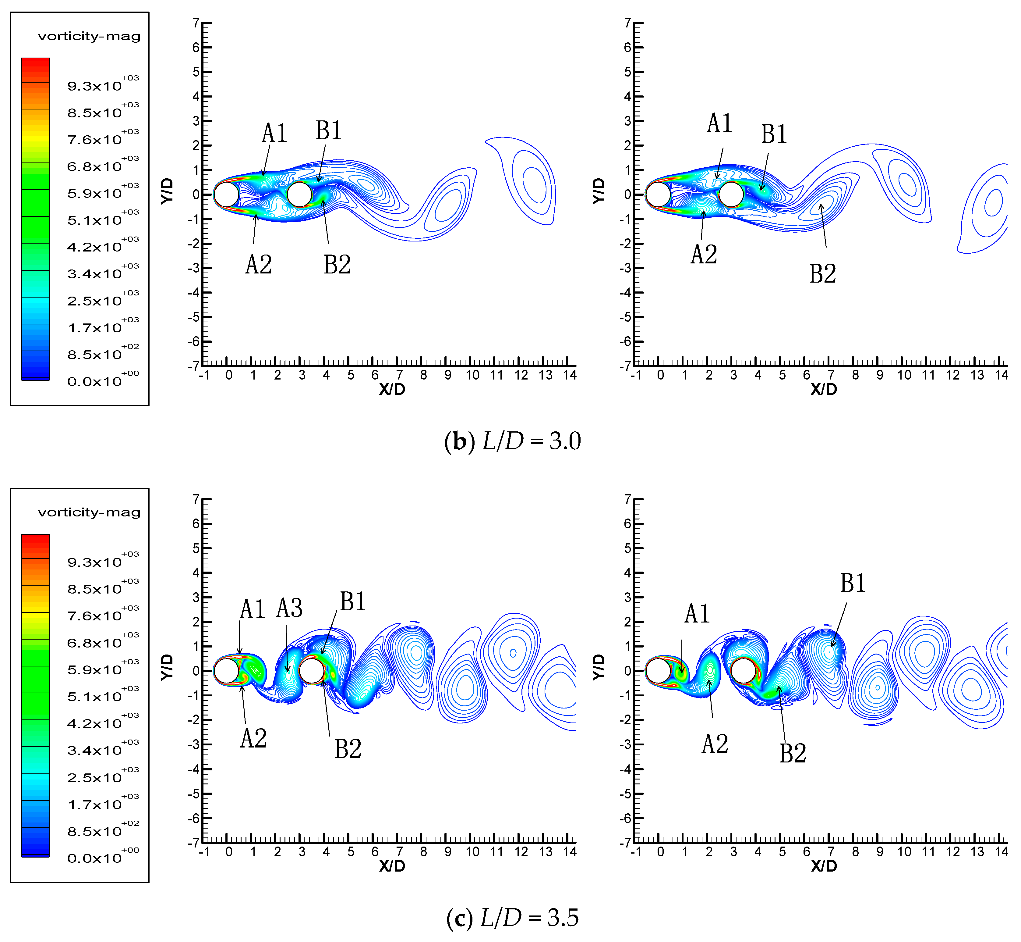
3.3. Streamwise Cylinders

As for the two cylinders with the streamwise arrangement, also three cases of cylinder spacing are considered in the present study, and the simulated hydrodynamic performances are summarized in Table 8. The subscripts C1 and C2 in Table 8 denote the upstream cylinder and the downstream cylinder, respectively. As shown in Table 8, for the streamwise arrangement, the drag coefficient of the upstream cylinder almost keeps constant at the level lower than that of a single cylinder when the cylinder spacing is relatively small (L/D < 3.0). However, when the cylinder spacing further increases, the drag coefficient of the upstream cylinder will rise to a value higher than that of a single cylinder. By comparison, with the increase in the cylinder spacing, the drag coefficient of the downstream cylinder gradually increases, while the value is always significantly lower than that of the upstream cylinder. As for the Strouhal number, it decreases and then increases with the increase in cylinder spacing.
The circumferential distribution of the pressure coefficient on upstream cylinder 1 and downstream cylinder 2 are plotted in Figure 10. Because of the symmetric characteristics along the streamwise direction, only the circumferential distributions from 0° to 180° are displayed here. For upstream cylinder 1, the distribution of pressure coefficient of the streamwise cylinders is quite similar to that of a single cylinder. At the windward side, the pressure coefficients of the streamwise cylinders are almost the same as that of a single cylinder. However, the difference in pressure coefficients between a single cylinder and streamwise cylinders starts to appear when it comes to the leeward side, which indicates that the downstream cylinder mainly influences the leeward side of the upstream cylinder. Also, such difference gradually reduces with the increase in the cylinder spacing. As for downstream cylinder 2, the circumferential distribution of pressure coefficient shows a quite different characteristic. For small spacing of L/D = 2.5 or 3.0, the pressure coefficient at the windward side is even lower than at the leeward side. As cylinder spacing further increases to L/D = 3.5, the pressure coefficient at the windward side becomes higher than that at the leeward side again, which is closer to the distribution of a single cylinder.
The flow separation points are also calculated for the upstream and downstream cylinders, and the results are listed in Table 9. It can be found that the flow separation point moves upstream in the upstream cylinder, while it moves downstream in the downstream cylinder. Also, the flow separation for both upstream and downstream cylinders is always later than that of a single cylinder.
Figure 11 depicts the distribution of streamwise velocity along the y-direction at different downstream locations for a single cylinder and streamwise cylinders. From top to bottom they are the single cylinder, the upstream cylinder, and the downstream cylinder, respectively. The development of velocity distribution from U-shaped to V-shaped in the single-cylinder case does not exist in the streamwise cylinders. The velocity distribution downstream of the upstream cylinder is more complex than that of the downstream cylinder, especially in the case of small cylinder spacing, which mainly results from the blockage effect of the downstream cylinder.
Figure 12 illustrates the contour distribution of vorticity around streamwise cylinders at different cylinder spacings at (left) t = t0 and (right) t = t0 + 5/6T, where the symbols A and B denote the flow patterns induced by the upstream and downstream cylinders, respectively. At the small cylinder spacing of L/D = 2.5 and 3.0, before the shear layer has time to develop into a vortex, it is already blocked by the downstream cylinder and attaches again to the surface of the downstream cylinder. The shear layer from the upstream cylinder attached to the downstream cylinder merges with the downstream cylinder’s own shear layer, and then sheds with the vortex of the downstream cylinder. Such reattachment contributes to the increase in the pressure coefficient in the downstream cylinder, as shown in Figure 10b. By comparison, when it comes to the large cylinder spacing of L/D = 3.5, the cylinder spacing is sufficiently large for the full development of shear layers. Therefore, the double-cylinder flow pattern is switched from the reattachment regime to the vortex-shedding regime. As shown in Figure 12c, the vortex structure A3 sheds from the upstream cylinder and then merges with the attached shear layer on the downstream cylinder. This development promotes the vortex shedding from the downstream cylinder. Therefore, the Strouhal number at the large cylinder spacing is higher than that at small cylinder spacings because the vortex-shedding process is accelerated by the merging of the shedding vortex from the upstream cylinder and the shear layer on the downstream cylinder. According to the above discussion, it can be summarized that the interaction of two streamwise cylinders will suppress the vortex formation of the upstream cylinder when cylinder spacing is small.
Moreover, as indicated in Du X, et al. [42]’s and de Moraes and Pereira [43]’s studies, the surface roughness of the cylinder can also significantly influence the flow characteristics. When rough cylinder surfaces are applied, both drag and Strouhal numbers reduce compared with a smooth cylinder surface, as do instabilities. Also, it is pointed out that the surface roughness of the downstream cylinder has a larger influence in the streamwise arrangement.

4. Conclusions

Large eddy simulations are carried out in the present study to investigate the flow characteristics around double cylinders with crosswise and streamwise arrangements. According to the numerical results, the following conclusions can be drawn.
The influences of the number of mesh cells, the first near-wall mesh size, and the transient time step on the simulation results are studied systematically to determine the proper parameters for accurate and efficient simulations. After determining all these numerical settings, the relative errors of time-averaged drag coefficient and Strouhal number compared with the existing experimental data are 1.88% and 0.14%, respectively, which validates the accuracy of the present numerical method.
For crosswise arrangements, the drag coefficient is always higher than that of the single cylinder. The stagnation points for both cylinders deviate toward the spacing side due to their interactions with each other. With an increase in the cylinder spacing, the flow pattern switches from a single-body regime to a synchronized vortex-shedding regime because of weaker interaction.
For streamwise arrangements, as cylinder spacing increases, the drag coefficient of the upstream cylinder gradually increases from a lower value to a higher one compared with the single cylinder, while the drag coefficient of the downstream cylinder is always smaller. Also, the flow separation point moves upstream in the upstream cylinder, while it moves downstream in the downstream cylinder. The flow pattern develops from the reattachment regime to the vortex-shedding regime.
As this study is aimed at ocean wave energy utilization, it is straightforward to perform further simulations of fluid–solid interaction that consider the vibration of multiple cylinders. By means of such analysis, the vortex-induced vibrations of multiple cylinders can be investigated in detail. This remains to be future researched.

Author Contributions

Methodology, W.Z., M.L., C.H. and D.C.; formal analysis, W.Z., M.L., C.H. and D.C.; writing—original draft preparation, W.Z. and M.L.; writing—review and editing, L.T.; visualization, C.H. and D.C.; supervision, L.T.; project administration, L.T.; funding acquisition, L.T. All authors have read and agreed to the published version of the manuscript.

Funding

This work was funded by the State Key Laboratory of Hydroscience and Engineering [sklhse-2023-E-01] and the State Key Laboratory of Hydroscience and Engineering [sklhse-2022-E-02].

Data Availability Statement

The data that support the findings of this study are available from the corresponding author upon reasonable request.

Conflicts of Interest

The authors declare no conflict of interest. Changjiu Huang is employed by State Grid Sichuan Electric Power Company. The remaining authors declare that the research was conducted in the absence of any commercial or financial relationships that could be construed as a potential conflict of interest.

References

  1. Lin, Y.; Bao, J.; Liu, H.; Li, W.; Tu, L.; Zhang, D. Review of hydraulic transmission technologies for wave power generation. Renew. Sustain. Energy Rev. 2015, 50, 194–203. [Google Scholar] [CrossRef]
  2. Rehman, S.; Alhems, L.M.; Alam, M.; Wang, L.; Toor, Z. A review of energy extraction from wind and ocean: Technologies, merits, efficiencies, and cost. Ocean Eng. 2022, 267, 113192. [Google Scholar] [CrossRef]
  3. Heikkinen, H.; Lampinen, M.; Boling, J. Analytical study of the interaction between waves and cylindrical wave energy con-verters oscillating in two modes. Renew. Energy 2013, 50, 150–160. [Google Scholar] [CrossRef]
  4. Liu, H.X.; Zhang, W.C.; Zheng, X.B.; Zhang, L.; Zhang, X.W.; Cui, L. Wave energy conversion by cylinder array with a floating platform considering linear/nonlinear PTO damping. J. Mar. Sci. Technol. 2017, 22, 747–757. [Google Scholar] [CrossRef]
  5. Sung, H.G.; Baek, H.; Hong, S.; Choi, J.-S. Numerical study of vortex-induced vibration of pivoted cylinders. Ocean Eng. 2015, 93, 98–106. [Google Scholar] [CrossRef]
  6. Simpson, R.L. Junction flows. Annu. Rev. Fluids Mech. 2001, 33, 415–443. [Google Scholar] [CrossRef]
  7. Grandemange, M.; Gohlke, M.; Cadot, O. Turbulent wake past a three-dimensional blunt body. Part 1. Global modes and bi-stability. J. Fluid Mech. 2013, 722, 51–84. [Google Scholar] [CrossRef]
  8. Hourigan, K.; Thompson, M.; Tan, B. Self-sustained oscillations in flows around long blunt plates. J. Fluids Struct. 2001, 15, 387–398. [Google Scholar] [CrossRef]
  9. Gonçalves, R.; Franzini, G.; Rosetti, G.; Meneghini, J.; Fujarra, A. Flow around circular cylinders with very low aspect ratio. J. Fluids Struct. 2015, 54, 122–141. [Google Scholar] [CrossRef]
  10. Pinar, E.; Ozkan, G.M.; Durhasan, T.; Aksoy, M.M.; Akilli, H.; Sahin, B. Flow structure around perforated cylinders in shallow water. J. Fluids Struct. 2015, 55, 52–63. [Google Scholar] [CrossRef]
  11. Ong, L.; Wallace, J. The velocity field of the turbulent very near wake of a circular cylinder. Exp. Fluids 1996, 20, 441–453. [Google Scholar] [CrossRef]
  12. Wang, H.; Tan, L.; Liu, M.; Liu, X.; Zhu, B. Numerical Investigation on the Transition Flow around NLF Airfoil. Energies 2023, 16, 1826. [Google Scholar] [CrossRef]
  13. Liu, M.; Tan, L.; Liu, Y.; Xu, Y.; Cao, S. Large eddy simulation of cavitation vortex interaction and pressure fluctuation around hydrofoil ALE 15. Ocean Eng. 2018, 163, 264–274. [Google Scholar] [CrossRef]
  14. Liu, M.; Tan, L.; Cao, S. Cavitation–Vortex–Turbulence Interaction and One-Dimensional Model Prediction of Pressure for Hydrofoil ALE15 by Large Eddy Simulation. J. Fluids Eng. 2019, 141, 021103. [Google Scholar] [CrossRef]
  15. Lo, S.-C.; Hoffmann, K.A.; Dietiker, J.-F. Numerical Investigation of High Reynolds Number Flows over Square and Circular Cylinders. J. Thermophys. Heat Transf. 2005, 19, 72–80. [Google Scholar] [CrossRef]
  16. Breuer, M. Numerical and modeling influences on large eddy simulations for the flow past a circular cylinder. Int. J. Heat Fluid Flow 1998, 19, 512–521. [Google Scholar] [CrossRef]
  17. Lysenko, D.A.; Ertesv Aa GI, S.; Rian, K.E. Large-eddy simulation of the flow over a circular cylinder at Reynolds number 3900 using the OpenFOAM toolbox. Flow Turbul. Combust. 2012, 89, 491–518. [Google Scholar] [CrossRef]
  18. Kravchenko, A.G.; Moin, P. Numerical studies of flow over a circular cylinder at ReD=3900. Phys. Fluids 2000, 12, 403–417. [Google Scholar] [CrossRef]
  19. Ma, X.; Karamanos, G.-S.; Karniadakis, G.E. Dynamics and low-dimensionality of a turbulent near wake. J. Fluid Mech. 2000, 410, 29–65. [Google Scholar] [CrossRef]
  20. Rodi, W. Large-Eddy Simulations of the Flow past Bluff Bodies: State-of-the Art. JSME Int. J. Ser. B 1998, 41, 361–374. [Google Scholar] [CrossRef]
  21. Shao, J.; Zhang, C. Large eddy simulations of the flow past two side-by-side circular cylinders. Int. J. Comput. Fluid Dyn. 2008, 22, 393–404. [Google Scholar] [CrossRef]
  22. Huang, H.; Zhang, J.; Meng, J. Large eddy simulation of flows past an array of square cylinders. J. Hydraul. Res. 2023, 61, 288–297. [Google Scholar] [CrossRef]
  23. Wang, X.; Gong, K.; Liu, H.; Zhang, J.-X.; Tan, S. Flow around four cylinders arranged in a square configuration. J. Fluids Struct. 2013, 43, 179–199. [Google Scholar] [CrossRef]
  24. Sewatkar, C.M.; Patel, R.; Sharma, A.; Agrawal, A. Flow around six in-line square cylinders. J. Fluid Mech. 2012, 710, 195–233. [Google Scholar] [CrossRef]
  25. Dubois, R.; Andrianne, T. Flow around tandem rough cylinders: Effects of spacing and flow regimes. J. Fluids Struct. 2021, 109, 103465. [Google Scholar] [CrossRef]
  26. Lam, K.; Gong, W.; So, R. Numerical simulation of cross-flow around four cylinders in an in-line square configuration. J. Fluids Struct. 2008, 24, 34–57. [Google Scholar] [CrossRef]
  27. Meneghini, J.; Saltara, F.; Siqueira, C.; Ferrari, J. Numerical simulation of flow interference between two circular cylinders in tandem and side-by-side arrangements. J. Fluids Struct. 2001, 15, 327–350. [Google Scholar] [CrossRef]
  28. Sharman, B.; Lien, F.S.; Davidson, L.; Norberg, C. Numerical predictions of low Reynolds number flows over two tandem circular cylinders. Int. J. Numer. Methods Fluids 2005, 47, 423–447. [Google Scholar] [CrossRef]
  29. Zhou, Y.; Yiu, M.W. Flow structure, momentum and heat transport in a two-tandem-cylinder wake. J. Fluid Mech. 2006, 548, 17–48. [Google Scholar] [CrossRef]
  30. Xu, S.J.; Zhou, Y.; So, R.M.C. Reynolds number effects on the flow structure behind two side-by-side cylinders. Phys. Fluids 2003, 15, 1214–1219. [Google Scholar] [CrossRef]
  31. Alam, M.; Moriya, M.; Sakamoto, H. Aerodynamic characteristics of two side-by-side circular cylinders and application of wavelet analysis on the switching phenomenon. J. Fluids Struct. 2003, 18, 325–346. [Google Scholar] [CrossRef]
  32. Sumner, D.; Wong, S.; Price, S.; Païdoussis, M. Fluid behaviour of side-by-side circular cylinders in steady cross-flow. J. Fluids Struct. 1999, 13, 309–338. [Google Scholar] [CrossRef]
  33. Chen, L.; Tu, J.; Yeoh, G. Numerical simulation of turbulent wake flows behind two side-by-side cylinders. J. Fluids Struct. 2003, 18, 387–403. [Google Scholar] [CrossRef]
  34. Qiu, X.; Bi, Z.-X.; Luo, J.-P.; Liu, Y.-L. Vortex shedding in the flow around two side-by-side circular cylinders of different diameters. J. Hydrodyn. 2017, 29, 470–478. [Google Scholar] [CrossRef]
  35. Palau-Salvador, G.; Stoesser, T.; Rodi, W. LES of the flow around two cylinders in tandem. J. Fluids Struct. 2008, 24, 1304–1312. [Google Scholar] [CrossRef]
  36. Prsic, M.A.; Ong, M.C.; Pettersen, B.; Myrhaug, D. Large Eddy simulations of flow around tandem circular cylinders in the vicinity of a plane wall. J. Mar. Sci. Technol. 2019, 24, 338–358. [Google Scholar] [CrossRef]
  37. Hu, X.; Zhang, X.; You, Y. On the flow around two circular cylinders in tandem arrangement at high Reynolds numbers. Ocean Eng. 2019, 189, 106301. [Google Scholar] [CrossRef]
  38. Franke, J.; Frank, W. Large eddy simulation of the flow past a circular cylinder at ReD=3900. J. Wind. Eng. Ind. Aerodyn. 2002, 90, 1191–1206. [Google Scholar] [CrossRef]
  39. Lesieur, M.; Metais, O. New trends in large-eddy simulations of turbulence. Annu. Rev. Fluid Mech. 1996, 28, 45–82. [Google Scholar] [CrossRef]
  40. Bose, S.T.; Park, G.I.; Davis, S.H.; Moin, P. Wall-Modeled Large-Eddy Simulation for Complex Turbulent Flows. Annu. Rev. Fluid Mech. 2018, 50, 535–561. [Google Scholar] [CrossRef]
  41. ANSYS Help, 17.0; ANSYS Inc.: Canonsburg, PA, USA, 2017.
  42. Du, X.; Lin, W.; Wu, G.; Daichin; Jiang, B. Effects of surface roughness on the wake-induced instabilities of two circular cylinders. J. Fluids Struct. 2019, 91, 102738. [Google Scholar] [CrossRef]
  43. de Moraes, P.G.; Pereira, L.A.A. Surface Roughness Effects on Flows Past Two Circular Cylinders in Tandem Arrangement at Co-Shedding Regime. Energies 2021, 14, 8237. [Google Scholar] [CrossRef]
Figure 1. Schematic of flows around cylinder.
Energies 16 07605 g001
Figure 2. Schematic of the computational domain for (a) Single cylinder, (b) Crosswise cylinder, and (c) Streamwise cylinder.
Energies 16 07605 g002aEnergies 16 07605 g002b
Figure 3. Computational mesh for (a) Single cylinder and (b) Double cylinders.
Energies 16 07605 g003
Figure 4. Time evolution of drag coefficient (red color) and lift coefficient (blue color).
Energies 16 07605 g004
Figure 5. (a) Mean pressure coefficient around single cylinder and (b) definition of circumferential angle θ.
Energies 16 07605 g005
Figure 6. Mean streamwise velocity at downstream locations for a single cylinder for (a) Re = 1000, (b) Re = 2000, (c) Re = 3000, (d) Re = 3900, (e) Re = 5000, (f) Re = 6000, (g) Re = 7000, (h) Re = 8000, and (i) Re = 10,000.
Energies 16 07605 g006aEnergies 16 07605 g006b
Figure 7. Mean pressure coefficient around cylinders with crosswise arrangement for (a) Cylinder 1 and (b) Cylinder 2.
Energies 16 07605 g007
Figure 8. Mean streamwise velocity at downstream locations for crosswise cylinders.
Energies 16 07605 g008
Figure 9. Vorticity distribution around crosswise cylinders at (left) t = t0 and (right) t = t0 + 5/6T for (a) T/D = 1.2, (b) T/D = 1.6, and (c) T/D = 2.5.
Energies 16 07605 g009
Figure 10. Mean pressure coefficients around cylinders with streamwise arrangement for (a) Cylinder 1 and (b) Cylinder 2.
Energies 16 07605 g010
Figure 11. Mean streamwise velocity at downstream locations for streamwise cylinders for (a) L/D = 2.5, (b) L/D = 3.0, and (c) L/D = 3.5.
Energies 16 07605 g011aEnergies 16 07605 g011b
Figure 12. Vorticity distribution around streamwise cylinders at (left) t = t0 and (right) t = t0 + 5/6T for (a) L/D = 2.5, (b) L/D = 3.0, and (c) L/D = 3.5.
Energies 16 07605 g012aEnergies 16 07605 g012b
Table 1. Independence test of number of mesh cells.
MeshMesh
Distribution
(r × θ × z)
Number of Mesh CellscDRelative
Error of cD
StRelative
Error of St
Mesh 150 × 120 × 350.78 × 1060.9771.31%0.18912.06%
Mesh 270 × 120 × 481.82 × 1060.9810.81%0.2016.77%
Mesh 390 × 200 × 582.80 × 1060.9781.17%0.2092.99%
Table 2. Independence test of cell size of the first near-wall layer.
MeshNumber of Mesh CellsCell Size of the First Layery+cDRelative
Error of cD
StRelative
Error of St
Mesh 2-11.82 × 1060.0180.9820.81%0.2006.77%
Mesh 2-21.82 × 1060.0055.60.9652.56%0.2045.26%
Mesh 2-31.82 × 1060.0011.50.9711.88%0.2150.14%
Mesh 2-41.82 × 1060.00050.80.9850.47%0.2254.68%
Mesh 2-51.82 × 1060.00010.51.0172.73%0.2317.44%
Table 3. Independence test of transient time step.
Δt (s)cDRelative Error of cDStRelative Error of St
1 × 10−40.9711.88%0.21530.14%
5 × 10−51.0172.72%0.22896.47%
1 × 10−50.9137.78%0.22092.76%
Table 4. Hydrodynamic parameters of flow around a single cylinder.
CaseRecDSt
110001.2100.210
220000.976 0.211
330000.983 0.214
439000.971 0.215
550000.974 0.196
660000.943 0.186
770000.916 0.175
880000.892 0.165
910,0000.855 0.153
Table 5. Flow separation parameter of a single cylinder.
CaseReθsep
1100092.25
2200088.18
3300086.40
4390085.66
5500084.74
6600083.50
7700082.46
8800081.65
910,00080.64
Table 6. Hydrodynamic performance of crosswise cylinders.
CaseT/DcD,sSt
Case Single0, single cylinder1.000.215
Case T1.21.21.410.098
Case T1.61.61.100.215
Case T2.52.51.370.264
Table 7. Flow separation parameter of side-by-side cylinders.
CaseT/DCylinder 1Cylinder 2
θstaθsesθseo|θsesθseo|θstaθsesθseo|θsesθseo|
Single0027288
T1.21.219.31284.98100.84184.14338.2174.89250.47175.58
T1.61.69.81278.398.02180.28347.2481.56255.27173.71
T2.52.54.64273.7995.77178.02355.1486.46264.11177.65
Table 8. Flow separation parameter of streamwise cylinders.
CaseL/DcD,C1cD,C2St
Case Single0, single cylinder1.2100.215
Case L2.52.50.917−0.0800.136
Case L3.03.00.9150.1680.126
Case L3.53.51.3700.3070.2
Table 9. Flow separation parameter of streamwise cylinders.
CaseL/DUpstream Cylinder 1Downstream Cylinder 2
θsepθsep
Single088
L2.52.593.04119.74
L3.03.092.57120.78
L3.53.590.18125.48
Disclaimer/Publisher’s Note: The statements, opinions and data contained in all publications are solely those of the individual author(s) and contributor(s) and not of MDPI and/or the editor(s). MDPI and/or the editor(s) disclaim responsibility for any injury to people or property resulting from any ideas, methods, instructions or products referred to in the content.

