Review

Methodology for the Optimization of a Novel Hydro Turbine with a Case Study

School of Engineering, Lancaster University, Lancaster LA1 4YW, UK
*
Author to whom correspondence should be addressed.
Energies 2023, 16(22), 7591; https://doi.org/10.3390/en16227591
Submission received: 22 September 2023 / Revised: 30 October 2023 / Accepted: 13 November 2023 / Published: 15 November 2023
(This article belongs to the Section A: Sustainable Energy)

Abstract

:
As the world strives towards its goal of net zero carbon emissions, it is vital that renewable energy sources be optimized to their full potential. A key source of renewable energy is hydropower, more specifically, the Pelton turbine—a highly efficient, widely used, and well-researched piece of turbomachinery. This review proposes a methodology that will aid future research on Pelton turbines and compares relevant literature to assess effective ways to improve upon the Pelton design. The methodology evaluates how both experimental and computational analysis can be utilized in parallel to accelerate the progress of research, giving an example of the adopted workflow presented in a case study. The literature study in this paper focuses on how a variety of bucket parameters can be optimized to improve the efficiency of a Pelton turbine and analyses the accuracy of CFD compared to experimental data from previous research involving Pelton and Turgo turbines. The findings revealed that a water exit angle of 169°–170° proved to be optimal, while modifications to the depth and internal geometry of the bucket seemed to have the greatest impact on the efficiency of Pelton turbines. A short discussion on the potential for utilizing the strengths of both Pelton and Turgo turbines is included to highlight the need for further research in this field. A combination of both simulation and experimental results running in parallel with each other during optimization is found to be beneficial due to advancements in rapid prototyping. By comparing experimental data with simulated data throughout the optimization process, mistakes can be realized early on in the process, reducing time in later stages. Having experimental data throughout the turbine’s development aids the computational process by highlighting issues that may have been missed when only using CFD.

1. Introduction

Renewable energy is of particular interest for its reduced environmental impact [1]. However, the source of energy, be it wind, solar, or tidal, cannot be relied upon for consistent production. Hydropower can provide a more consistent, predictable, and, crucially, controllable supply than other renewable energy technologies and thus represents a critical component for transitioning to a fully renewable energy supply. The Pelton turbine is a high-efficiency, high-head hydro turbine capable of reaching 95% efficiency [2] and is widely used in pumped energy storage schemes [3,4]. Pumped energy storage is an excellent way to store large volumes of water for conversion to electricity at times of high demand. This is of particular interest in the modern world moving towards a potentially renewable-based grid, as it provides another defense against the variability of both energy supply and demand.
However, Pelton turbines are subject to performance losses with erosion from the fluid along its central splitter. This is a concern largely for two reasons. One is simply that it reduces the capacity to extract the energy from the fluid; the second is that pumped hydro storage operates at a net loss of energy due to other unavoidable inefficiencies in the system; this would be exacerbated if the Pelton turbine were to have any erosion. This is particularly key as energy demands are projected to increase, making efficiency of generation a key feature in production.
Alternative turbines, such as the Turgo and Francis turbines [5,6,7,8,9], do not typically achieve efficiencies as high as those achieved by Pelton turbines and have added complexity to their control. Much of the performance degradation of a Pelton turbine comes from the splitter, a geometry designed to split the water jet evenly for fluid to flow into both of the buckets [10]. A novel approach would be to try and combine elements of different turbine designs to maximize the performance and durability of the turbine.
The design of the Pelton turbine is very specific, and its mode of operation is well described in Figure 1.
It also highlights the importance of the splitter remaining sharp to be effective in maximizing efficiency. It would, therefore, be potentially beneficial to combine aspects of turbines that do not require sharp elements within the Pelton turbine to eliminate the effect of corrosion.
The high performance is partly down to the splitter on the front of the buckets that make up the turbine; although this is a feature that brings high performance, it is also subject to erosion, which reduces the performance of the turbine. The erosion of the splitter reduces the performance efficiency and makes it necessary to have regular maintenance to sharpen the splitter. During this downtime, there can be no production, and therefore, overall performance is lost in energy generation [11,12,13]. It is stated that, as a general rule of thumb, when the thickness of the splitter is increased to 1% of the bucket width due to erosion, the efficiency of the turbine is reduced by 1% [13]; thus, it is important to retain that extremely thin edge on the bucket splitter.
Other turbines, such as Turgo turbines (the design of which is explored in Section 2.1.2), eliminate the need for the splitter by having an angled water jet that hits the turbine at around 20 degrees from the perpendicular offset. Although this reduces the pressure on the splitter to provide performance, there are still efficiency losses as the water jet does not contact the turbine at the perpendicular. Furthermore, the Turgo turbine essentially has only one “bucket”, although this is angled and does not interact with the water jet in the same way. Without a splitter losing its sharpness, Turgo turbines can spend longer in use before requiring downtime for service, which would be advantageous in a number of fields. The lack of a splitter that is so inherently linked to performance is particularly appealing and could represent a solution where maintenance is more challenging, such as in remote environments.
The concept of the Turgo turbine is particularly appealing with durability, whilst the Pelton turbine represents the highest overall efficiency available. A novel design merging the best features of both styles would be an effective way to try and maximize the combination of durability and performance. Eliminating the requirement for a splitter would be advantageous as this is a key area where performance is lost; while removing the inlet angle of the water jet would also represent an improvement in the available energy for the turbine to convert. This would lead to a novel design where the water jet is intended to line up with a singular bucket, but significantly, without the inlet angle seen in the Turgo turbine.
Having the water jet interact with one bucket would remove the requirement for a splitter to aid in the water flow. This was the motivation to study further the impact that these design changes would have on the performance of the turbine. When combining these two styles of turbine, it would be interesting to analyze the effect that the novel design would have, both in durability and efficiency.

2. Previous Attempts to Optimize Design Parameters

2.1. Description of the Pelton and Turgo turbines

2.1.1. Pelton Turbine

The operation of a Pelton turbine utilizes high-speed jets of water, which are directed from the nozzles that surround the turbine. A Pelton turbine consists of buckets that “catch” the water jet and redirect the flow backward [14]; each bucket consists of two halves separated by the splitter. The water jet from the nozzle hits the bucket at the splitter, where the water jet is divided into two equal streams. These two separate streams then travel along the inner arc of the bucket and leave in the opposing direction from which it entered. The following change in the momentum of water creates an impulse on the blades of the turbine, generating torque and rotation in the turbine [15]. Pelton turbines are used on medium to high-head hydropower sites with heads from 20 m to hundreds of meters [2].
The shape of the Pelton bucket is designed so that the jet of water is directed away at almost a 180-degree angle in order to transfer the kinetic energy with the least amount of splashing and leave enough energy for the water jet to exit the rotor fully. This ensures that almost none of the water hits the next bucket and, therefore, eliminates any potential drag. The surface of the Pelton buckets is well polished to reduce drag, and the rotor itself is finely balanced to remove rotational instability. The cut-out at the tip of the bucket means that the next bucket does not enter the jet of water, impacting the previous bucket prematurely as the rotor rotates [2]. A diagram of the jet flow through the Pelton bucket is shown in Figure 1.
Figure 1. Diagram of the Pelton turbine from an aerial and forward view where d0 = jet diameter (m), C1 = jet velocity (m/s), U1 = circumferential velocity of buckets (m/s), and W1 = work done on the buckets (J).
Energies 16 07591 g001
In 1880, Lester Pelton developed the Pelton turbine. He made this discovery when analyzing the flow in cups when the jet accidentally became misaligned towards the edge of the cup compared to the center. As the water hit the edge, its velocity increased, therefore, to take advantage of this increase, he incorporated a divider in the center of the cup. This divider splits the water jet into two separate jets, redirecting them back through nearly 180°. Three years later, Lester Pelton won an award for the most efficient water wheel creating a Pelton turbine with 90.2% efficiency [16,17]. Through to the present day, the Pelton turbine remains the most efficient impulse hydro turbine. Through the use of new tooling and simulation software, along with commercial competition, the Pelton turbine continues to improve in efficiency, with current designs reaching 95% [18]. For smaller-scale systems, 90% efficiency is achievable. On multiple spear-jet Pelton’s, operation at very high efficiencies is possible over a range of flow rates [2]. There are four main sections of interest for efficiency analysis when looking at the Pelton turbine. These include the distributor, nozzle, bucket, and casing. The distributor and nozzle can be categorized together as they primarily focus on the jet efficiency, focusing on the longevity of the system. In contrast, the optimization of the casing and the buckets looks at increasing the overall efficiency of the buckets, assuming no losses in the nozzle and distributor [18].

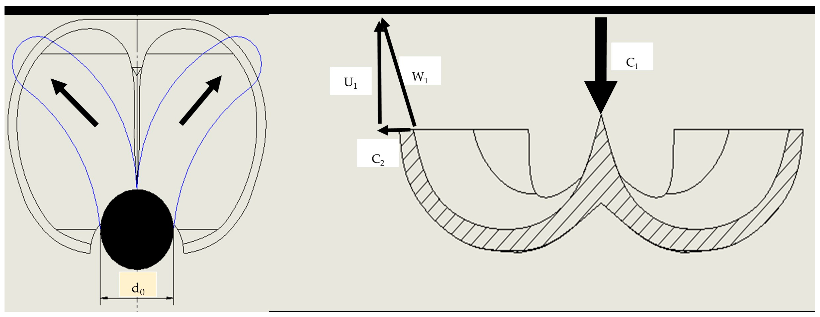
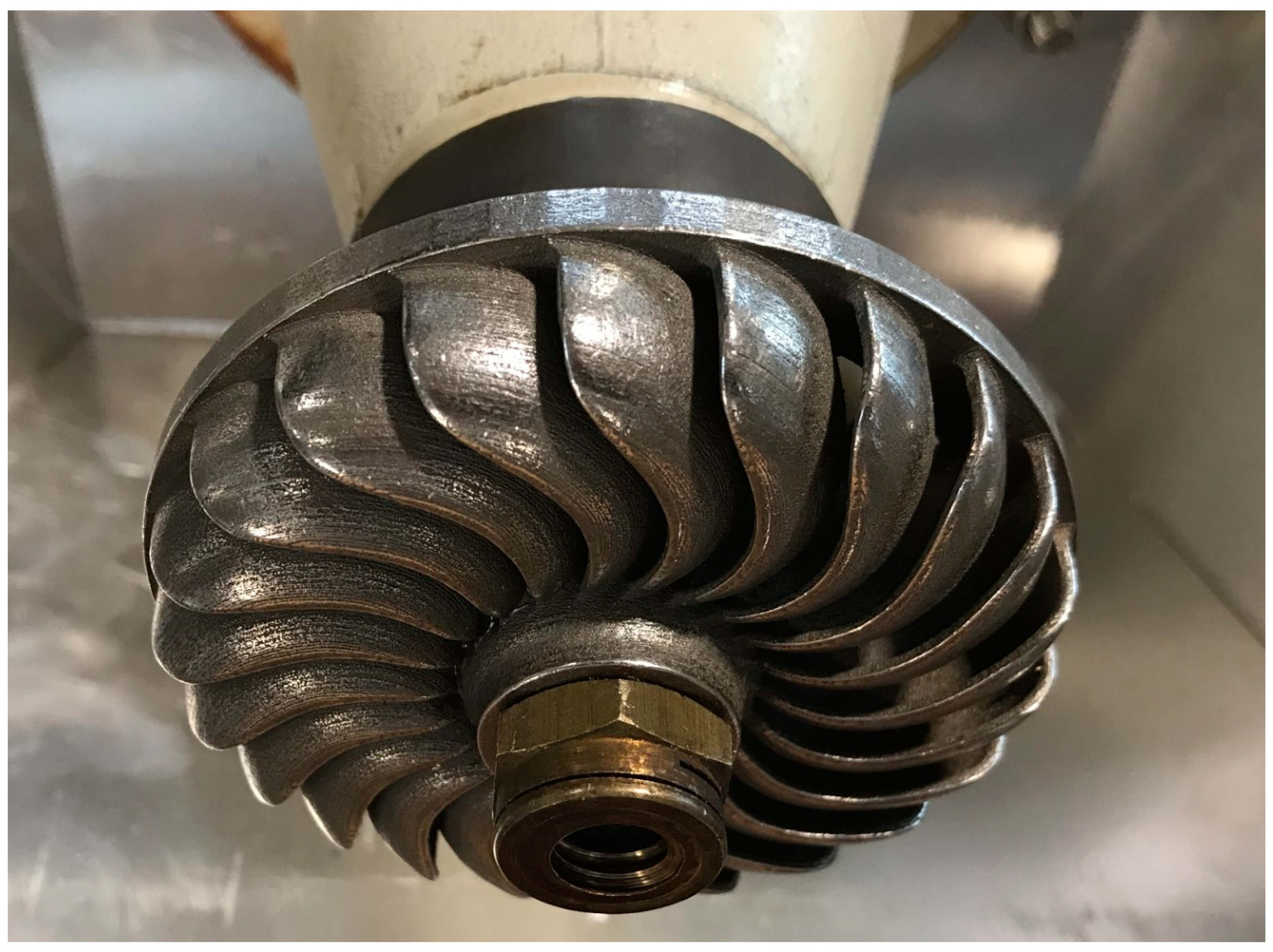
2.1.2. Turgo Turbine

The Turgo turbine functions in a very similar manner to that of the Pelton turbine. High-velocity jets of water exit from the nozzles that are positioned around the turbine—these nozzles are placed so the water jet will hit the buckets on one side at an angle of around 20° [19]. Figure 2 and Figure 3 show examples of Pelton and Turbo turbine designs, respectively.
The shallow angle of the buckets allows the water flow to exit on the opposite side instead of being diverted backwards. Unlike Pelton turbines, the incoming and outgoing jets do not interfere, meaning that the Turgo is able to allow higher flow rates [19].
Despite the ability to deal with high flow rates, Turgo turbines are, to some degree, less efficient than their Pelton counterparts [19]. The primary explanation for this lower efficiency is the less sturdy runner vanes/buckets. However, while the efficiency of the Turgo turbine is typically less than that of the Pelton turbine, it does provide a more cost-effective way to generate electricity from medium/small heads of 15 m to 300 m. Turgo turbines are therefore commonly installed in the head range where Pelton and Francis turbines overlap [20]. The turbine extracts energy using the variation in kinetic energy of the water entering and leaving the turbine at atmospheric pressure—thus making it an impulse turbine [19,21]. One of the most notable distinctions between the shape of a Turgo turbine and a Pelton turbine is that Turgo turbines use a single bucket instead of the double buckets that are seen on the Pelton wheel. The single buckets on the Turgo usually have less depth than their Pelton counterparts [22].
In the present day, the efficiency of the newest Turgo turbines can be up to 90% with a laboratory setup. In hydropower plants, these efficiencies achieve about 87% [20]. While these efficiencies are still high, there is a clear reduction in efficiency when compared with a Pelton turbine.

2.2. Research to Date

The development of the Pelton design has been, and remains, an ongoing challenge to this day. The advancement in computational fluid dynamics (CFD) over the last couple of decades has made the possibility of improving the Pelton design more accessible and attainable.
Computational fluid dynamics (CFD) is the computational study of how fluids and solids interact with each other. Typically, CFD can be further separated into three distinct categories, finite difference method (FDM), finite element method (FEM), and finite volume method (FVM). Finite volume methods are the most recently developed methods combing elements of both the FEM and FDM models [23]. The Euler equations govern the motion of inviscid fluids alongside the Navier–Stokes equations that describe the motion of viscous fluids [24,25,26].
The aforementioned methods solve the three partial differential equations (PDEs) related to the fundamental principles of fluid flow. The three equations are listed below, showing the conservation of mass, energy, and momentum. These three equations can be written as [27]:
ρ t + . ρ V = 0 ( Conservation   of   Mass )
ρ dV dt = . τ i j p + ρ F ( Conservation   of   Momentum )
ρ de dt + p . V = Q t . q + Φ ( Conservation   of   Energy )
FDMs (Figure 4b) can be seen in use as far back as the 1920s, when physicists and mathematicians [28] applied Taylor series expansions to analyze the differences between two nodes on a meshed body. Later on, approximation errors were introduced, increasing the accuracy of the scheme [29]. FDMs can be used when looking to develop first- and second-order terms for structured grids on simple 3-D geometries; however, they will not be capable of solving complex geometries.
FEMs are an integral scheme, whereas FDMs are a differential scheme; this allows FEM to dissect an object into a small number of pieces known as elements, then applying the previously mentioned PDEs to each individual element to get a more detailed solution [30]. This method is typically the most frequently used industrial method as it provides a more detailed analysis of complex geometries; however, at a much larger computational cost [28,31].
FVM splits the geometry into grid cells where the total integral is then approximated along the entire cell (Figure 4a). Once the total integral has been computed, it is divided across the total cell volume, where an average is then derived [32]. Industrial work packages such as Ansys Fluent and Ansys CFX use this method; however, with slight variations from each other. Fluent uses cell-centered FVM, whereas CFX uses cell vertex FVM methods, although both are deemed to give reliable results [33].
In order to obtain a more advanced understanding of how optimization strategies and parameters (for Pelton turbines) using CFD have been utilized in the past, a variety of studies were investigated—focusing primarily on optimizing bucket geometry parameters.
In a project report paper conducted at Lancaster University by Pickston et al. [1] in 2023, the experimental and computational development of a novel high-head impulse turbine was investigated. The study looked at optimizing the design of the original Jubilee Pelton turbine (made from aluminum bronze [34,35]) to produce one of higher efficiency. Part of the research involved modifying the Pelton bucket design parameters and simulating the new designs using ANSYS CFX.
The investigation resulted in an increase in efficiency of 6.73%, from an initial 76.22% to 82.95%. The water exit angle of the optimal bucket was between 79 and 80° (169–170° taken from the vertical). It was found that there were significant improvements in the performance of the bucket when the size of the top rim of the bucket was reduced. Increasing the width of the bucket provided little improvement in the overall performance while increasing the depth provided a considerable increase in efficiency. Reducing the length of the bucket improved efficiency, and the inverse was true when the bucket was elongated. Another notable enhancement in the efficiency of the design was with a revised internal geometry. The new internal surface was significantly steeper on the sides than with the original, with a smoother transition of depth through the bucket, particularly in the main surface—designed to reduce kinetic losses in the flow of the fluid. The internal shape also contained a flatter section through the central profile, more akin to a Turgo turbine.
Erazo et al.’s study in 2022 [36] looked at the development of an analytical and iterative methodology that allowed for the determining of the appropriate dimensions of the Pelton buckets to achieve maximum turbine efficiency. A parametric model was proposed, which considered the dimensions and main angles of the bucket.
The results of the model were validated by means of CFD and contrasted with experimental data obtained from the “Illuchi N2” Hydroelectric Power Plant in Ecuador. From the report, it was found that the water exit angle (β) parameter had the largest influence on the efficiency of the Pelton turbine. It was noted that if this value were properly defined, the efficiency of the turbine could reach up to 95% when operated at full load. The width of the bucket (B) was found to maintain an inversely proportional relationship with the overall efficiency of the turbine. The length of the bucket (L) was deemed to have a reduced effect on the overall efficiency of the turbine when compared to the previously mentioned parameters. However, bucket length still behaved in the same way as the width parameter, as a reduction in this value led to an increase in efficiency [36]. For the case study stated within the report, it was concluded that the appropriate dimensions for the bucket design were β = 169°, B/do = 2.8, and L/do = 2.28, where do is the jet diameter [36].
Unsteady CFD simulation for bucket design optimization of the Pelton turbine runner was investigated by Kumashiro et al. in 2016 [37]. A numerical study on two different design buckets was introduced using ANSYS CFX 16.1. The model specification of “Bucket A” had parameter values of width = 3.6 do and length 3.2 do, and the model specification of “Bucket B” had parameter values of width = 3.3 do and length 2.8 do. From this, Bucket B had 0.89% the width of Bucket A and 0.85% the length of Bucket A.
The difference between the two models resulted in a 2–3% higher efficiency for Bucket B. This was explained in the report by the water being easily spread wide inside Bucket A (due to the larger inner surface area) and the low-pressure region being diverged widely. While the study did not provide optimal values for width and length, it did highlight a relationship between the two bucket geometry parameters and the efficiency of the Pelton turbine.
In 2015, a paper published by Židonis et al. focused on developing a generic optimization method for Pelton turbine runners using computational fluid dynamics (CFD). This study comprised two different bucket designs optimized with the aim of collecting generic data. For the optimization of design B mentioned in “case 2”, the Ansys CFX work package was used [38].
In Case 2 (DOE) Study 1, it was found that the bucket length-to-width ratio could alter the efficiency by up to 1%, while less than a 1% impact was discovered by changing the bucket depth-to-width ratio. When analyzing the impact of the splitter inlet angle, a 20° change in angle caused an efficiency change of 0.4%. In both bucket designs, the splitter inlet angle was identical; this suggested that the splitter inlet angle is independent of the overall design, further suggesting that there is an optimal angle at which the jet must be divided. The exit angle, however, is identified in the report to be of much greater importance when optimizing the flow inside the buckets and the direction in which the water exits. It was noted that one should reduce the exit angle to the lowest possible value. However, it is important to note that if the flow exiting the bucket impinges on the following bucket, the angle should be decreased [38]. By combining these factors, increasing the bucket length and depth along with optimizing the exit angle, an efficiency increase of 0.9% was possible.
As previously mentioned, the splitter inlet angle was independent of the design and had little impact on the overall efficiency of this study. Furthermore, after increasing the length and depth of the bucket in DOE study 1, it would make logical sense to alter the spacing between the buckets.
A summary of the review findings has been included in Table 1. Each individual study, while not identical, does investigate similar parameters throughout each paper. This allows one to compare the effect on turbine efficiency of modifying selected bucket parameters. In addition to optimizing bucket parameters, other optimizations, such as the induced Coanda effect [39,40,41,42] and the number of buckets [43,44], have also both been proven to have a notable impact on turbine efficiency. Table 1, therefore, also outlines optimizations that are not centered around bucket parametrization.

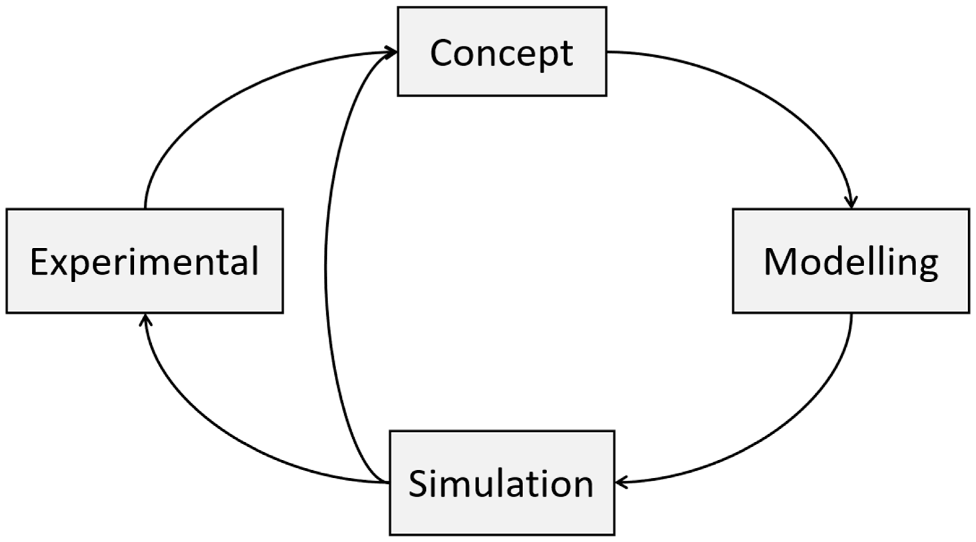
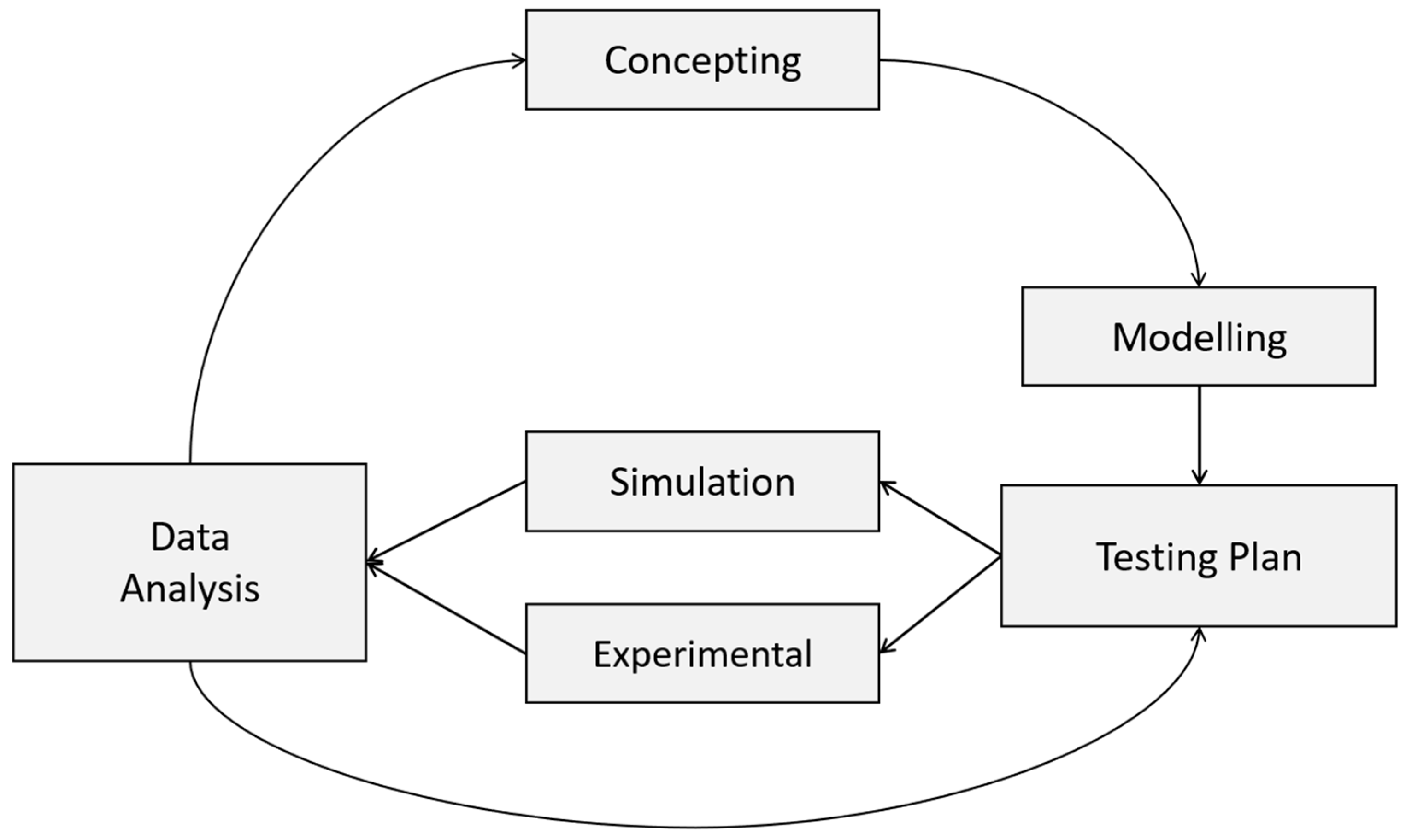
3. Overview of Workflow

The combination of experimental and simulated data is, of course, no new development. However, the specific method in which these separate methodologies and datasets were combined throughout the project is of note and significantly sped up the progression of the research conducted by Pickston et al. [1]. The primary methods for evaluating the performance of a new hydrodynamic machine such as a turbine are typically through computational fluid dynamics (CFD), a simulation method, and experimental testing. These two methods have inherent strengths and weaknesses, and much of the investment into these methods works to counteract these specific weaknesses. For example, CFD methods typically have very high accuracy but have significant computational overheads for each simulation. This effect is compounded for common CFD methods, as the test conditions are fixed for each simulation, meaning that many individual simulations must be conducted to build a holistic picture of the performance of the machine. In order to compare design iterations, this process must be repeated yet again. The most direct and simplest form of investment into CFD capability for research is investing in more powerful computers, reducing the simulation time of each data point.
In the case of experimental testing, its inherent strength is typically in far greater testing volume than would be possible with CFD. However, without significant investment, experimental testing can be prone to error and loss, which can make it difficult to isolate the performance of the machine itself from the performance of the machine in the context of the testing rig. It can often be difficult to isolate issues associated with experimental methods, such as inefficiencies within a testing rig, which further merits a combined approach to investigation.
The deficiencies of each method are particularly important when conducting novel research, such as the development of the novel impulse turbine. With little to no established research to use to compare with any obtained results, any errors or missing data can be significantly more difficult to separate from legitimate or reliable data. For the initial development of the novel turbine, the methods were combined in such a way that allowed the strength of each method to help address the weaknesses of the other method. A flowchart for this method is shown in Figure 5. This allowed for reliable data to be generated despite the issues with each method.
The initial workflow for developing a technology such as the novel impulse turbine is iterative, beginning with the concept phase. Concepting encompasses the theorizing of a new design, based on data obtained from the previous design in simulated and experimental testing, as well as potentially relevant pieces of literature or theory. Once a potential improvement is identified, a suitable model is generated with this improvement, forming the new design geometry. This is a particularly crucial step in the process due to the manufacturing processes employed. The importance of a robust model for CFD simulation is obvious, but this same model can be used to manufacture first-stage prototypes from SLS, or more robust second-stage prototypes via CNC machining. While some minor editing is required in order to prepare the raw simulated model for manufacture, using the same model as the basis of each mode of testing serves to minimize geometry differences as a cause of error between testing modes.
Once the model is completed, it is tested in a pre-established CFD simulation. The simulation parameters are chosen to match conditions that can be achieved in the experimental testing rig. Once the simulation is completed, the data is exported and processed to extract efficiency values from the raw simulated data (more detail covered in the project report paper by Pickston et al. [1]). This data informs the next conception phase, and if more data is required (typically if the design achieves higher efficiency in the range of test conditions), experimental testing is conducted. Before the new design bucket is manufactured, finite element analysis (FEA) is conducted on the bucket geometry to determine its durability [49,50,51,52,53,54,55,56,57,58,59,60].
Experimental testing is typically divided into multiple prototyping phases of increasing accuracy and investment. For the novel impulse turbine, a two-stage prototyping system was used. Initial testing was conducted using additive manufacturing, with components made from Nylon-12 [61,62,63] through selective laser sintering (SLS). These prototypes are relatively cheap and can be produced quickly. While Nylon-12 safely endured the testing regime for short lifespans (e.g., <5 tests), Nylon-12 can suffer fatigue failure over longer time periods, and, as such, was only used for short periods of testing. Its performance, while lower than the performance of the same design in a more rigid material like aluminum, was consistent both across designs and across retests of the same design, so within a band of limited testing, they provided solid early data.
If after extracting experimental performance data from the prototypes more data is desired, a larger investment of CNC-machined aluminum prototypes can be ordered. Due to material cost and difficulty in machining the complex geometry of the buckets, there is significant lead time and cost associated with the production of these second-stage prototypes. However, they exhibited consistently better performance than the same design in a first-stage prototype (SLS). Discussion of this paradigm is covered in the project report paper by Pickston et al. [1], but one reason is likely due to the relative stiffness of aluminum compared to Nylon-12. Experimental data from these prototypes is combined with the simulated data to inform the next conception stage.
The workflow shown in Figure 5 is a fairly generic representation of the development cycle of such a technology. The process has merit when developing with an extended schedule or significant resources. Experimental testing being employed secondarily to simulation is common and logical, as simulation provides high accuracy and does not entail the same investment as manufacturing prototypes. However, it is not the most effective when working with limited computational resources. Early into the development of the novel impulse turbine, a slightly different methodology was employed to great effect.
The primary distinction in the adopted workflow, illustrated in Figure 6 is in testing modes running parallel rather than in a linear dependency as in the generic workflow. In practice, simulation will still likely be the first data generated due to the lead time in manufacturing, even first-stage prototypes. However, both testing modes are employed as needed in order to provide insight into the full performance of the design. This is primarily motivated by the fact that with the resources available to this project, generating either a highly accurate performance landscape from experimental testing or a fully featured performance landscape from simulated testing, is highly impractical. Instead, they are employed in different scenarios. Experimental testing can quickly provide a broad understanding of the performance landscape of the prototype able to generate hundreds of data points per hour. However, due to the limitations of the testing equipment, it is unlikely ever to generate the level of precision that CFD simulation can. This simulated data is highly accurate and controllable but takes hours of simulation to generate a single data point. In this workflow, simulation is employed to collect data at specific points of interest, such as the best efficiency point (BEP). This highly accurate data can be combined with the experimental data in order to create an estimate of the true performance landscape despite the deficiencies with both testing methods.
However, there are some potential drawbacks or risks associated with such an approach. Primarily, it operates on the assumption that the efficiency difference between simulation and experiment is largely constant across the performance landscape. This behavior was seen in the collected data (Pickston et al. [1]), but this is specific to the testing rig used and will not be true universally. In more holistic applications of this methodology, some rounds of verification where coarse performance landscapes are gathered independently from experimental sources and simulated sources and compared against each other to ensure that the performance landscape is still consistent between data sources. It would also be best practice to periodically repeat this verification exercise, as due to the nature of the optimization problem, changes to the design may alter the performance in one testing methodology more than in another, resulting in datasets that in earlier designs were congruent but diverge after design iteration, potentially making it inappropriate to continue to combine them without further review. Secondly, it means that the ultimate peak efficiency is determined by the simulated data, and as a result, the exact parameters and simulation setup have a large impact on the final stated efficiency of the prototype.
In some scenarios, simple combination regimes like taking the mean of the two collected datasets may be viable, but due to the uncharacteristically low experimental efficiencies generated by the testing rig used, this would not have been appropriate. In more detailed research contexts, complex statistical models or machine learning approaches are designed and implemented in order to accurately and appropriately combine disparate datasets, such as in Duquesnoy et al. [64], where an artificial intelligence approach is used to combine modeled and experimental data. However, artificial intelligence approaches should be carefully evaluated before being used in a novel problem such as novel turbine optimization, as the expected outputs are inherently unknown and, therefore, difficult to predict. Another example of data-combination regimes is presented by Hill et al. [65], which conducts significant statistical analysis to both analyze simple methods such as averaging the data as previously discussed and proposes a new method for combining independent datasets called “conflation”. In summary, combining experimental and simulated datasets has incredible potential to accelerate the development of prototypes of devices such as hydro turbines, but the utmost care must be taken in how the resulting datasets are combined in order to maintain the reliability and accuracy of the results.

4. Comparison of Numerical and Experimental Results for Pelton Turbines

Across relevant literature, there are very limited studies that specifically focus on the Pelton turbine when comparing both numerical and experimental results. Two examples were, however, identified, which presented a direct comparison of the numerical results using CFD to experimentally gather data involving the efficiency of a Pelton turbine.
A study by Xiao et al. investigated both experimental and numerical findings of the dynamic performance of a Pelton turbine at five different operating conditions. Through the use of Ansys CFX 13 code [66] alongside the turbulent steady-state transport model, the simulations could be shown numerically. However, the report did acknowledge that the accuracy of simulations of the flow in Pelton turbines is still challenging at present times. It was recognized that this difficulty was due to many of the flow phenomena/interactions, which determine the performance of a Pelton turbine, having complex physics mechanisms that needed to be treated as fully transient [66]. Five operating conditions with the same unit speed were selected to compare with the field test relative efficiency results in this case, and their findings concluded that simulations were roughly 1–2% different compared to field test results [66].
From their results, the field test (experimental) and the simulation (numerical) results showed that the runner efficiency increased as the unit discharge increased, reaching a peak at the optimum discharge and then decreasing. The report concluded that the numerical results were sufficiently accurate to be used for efficiency predictions in this particular design process [66]. However, it should also be mentioned that the simulation results slightly underestimate the actual experimental data collected in the investigation. While the difference in relative efficiency was not drastic, it is worth noting that the simulation results and experimental results do have a discrepancy between them.
A subsequent report by Petley and Aggidis looked in depth at the effects of casing flow in a multi-jet horizontal axis Pelton turbine using comparisons with flow visualization data from the National Technical University of Athens. This report incorporates work done in Ansys Fluent using the Reynolds Averaged Navier Stokes equations (RANS) to simulate fluid flows alongside the k-ε turbulence model and the two-phase volume of the fluid model (VOF) [67].
From the results they gathered, the difference between the data both experimentally and computationally equates to roughly 3.5%. As stated in the findings, this number is marginally less than the errors stated in similar papers investigating the efficiencies of Pelton turbines both computationally and experimentally. It was concluded that it is not possible to quantifiably predict the efficiency of a full Pelton turbine using simulations alone. It was suggested that prototype modeling and testing should be done to consolidate theoretical efficiency gains gathered through computational modeling. However, it is recognized that as further advancements are made in the computational field and codes are improved, results will become more accurate. Until this point arrives, computational modeling should be used as a complementary design tool for improving casing design.
Assessing both reports, it can be concluded that while numerical analysis using CFD is beneficial to aid the design of a Pelton turbine, it cannot be fully relied on to obtain completely accurate results. The study from Xiao et al. [66] found that CFD slightly underestimated the experimental results, while the data from Petley and Aggidis highlighted that CFD was slightly overestimated when compared to experimental data. Knowing this, it would be impossible to state whether the CFD strategies under or overestimated the true value of efficiency from a Pelton turbine. However, in both cases, efficiencies from numerical results are close to that of the true experimental values—meaning that CFD can be considered a reliable tool when attempting to improve the design of the Pelton turbine.

5. Case Study

The case study of this review by Pickston et al. [1] (referred to in the abstract) details the optimized turbine design after combining both Pelton and Turgo turbines, along with modification of bucket design parameters. Table 1 within Section 2 highlights the optimizations that were made to the novel hydro turbine bucket from the case study.
This novel turbine in the case study is inspired by Pelton turbines but differs significantly by utilizing single buckets that resemble half of the traditional Pelton bucket, or similar to those implemented in a Turgo turbine. These “half buckets” are mounted on a backing disk. The primary proposed benefit of this “half bucket design”, as discussed in Section 1, is greater wear resistance than a traditional Pelton as the jet is directed to the bucket surface itself rather than the splitter. Furthermore, the parametric design optimizations on the turbine buckets resulted in improved turbine efficiency (details of which are presented in Section 2.2). Figure 7 shows the front view of the original Jubilee Pelton bucket, while Figure 8 demonstrates the same view of the best performing bucket design from the case study. A comparison between the two figures illustrates some of the visible differences between the two, such as the depth of the bucket.
The optimal bucket design was reached after multiple CFD simulations on a variety of different bucket designs. As discussed in Section 4, CFD is a reliable tool to be used to improve the design of Pelton turbines, thus, the utilization of it within the case study meant that an optimal design could be reached without pure reliance on manufacturing for experimental testing.
Further to design optimizations, the case study by Pickston et al. also implements the methodology examined in Section 3. The innovation of acquiring simulation and experimental data running in parallel, rather than in a linear dependency meant that the development and manufacture of newly designed turbine buckets was accelerated.

6. Conclusions

The concept discussed in this article would combine favorable design parameters of previously researched and studied turbines, namely the Pelton and Turgo turbines. Using the concept of a Pelton bucket, due to its high efficiency, and a Turgo single bucket approach, with its more durable design, could represent a good initial concept for further investigation.
While both turbines have excellent features, combining them could present a good opportunity to optimize a new design. This would have the potential application in pumped energy storage to replace the erosion-susceptible Pelton turbine currently used.
Employing simulated and experimental regimes in parallel would also represent a beneficial approach, as it would allow each method to offset the deficiencies of the other. Furthermore, experimental data can highlight issues that would be less likely to be detected in a simulation. Having an additional feedback loop into the development of the novel turbine would provide additional information to maximize performance further.
The concepts discussed could yield an increased overall performance in a novel turbine design, where high efficiency in a Pelton turbine meets with a more durable Turgo turbine. The idea of merging the two existing ideas is one that is certainly merited, and any output from the combined design would be extremely useful in understanding where further development and optimization of the novel concept turbine is.

Author Contributions

Conceptualization, G.A. and A.Ž.; methodology, D.P.; software, S.O. and L.W.; validation, D.P., L.B., M.D. and G.P.; data curation, D.P.; writing—original draft preparation, D.P., L.B. and L.W.; writing—review and editing, M.D., S.O. and G.P.; supervision, G.A. and A.Ž.; project administration, G.A. and D.P.; funding acquisition, A.Ž. All authors have read and agreed to the published version of the manuscript.

Funding

This research received no external funding.

Data Availability Statement

For any data required, please email the corresponding author.

Conflicts of Interest

The authors declare no conflict of interest.

References

  1. Pickston, D.; Orritt, S.; Wilmot, L.; Burtenshaw, L.; Dubois, M.; Prigov, G.; Aggidis, G. Experimental and Computational Development of a Novel High Head Impulse Turbine. Master’s Thesis, Lancaster University, Lancaster, UK, 2023. [Google Scholar]
  2. Pelton and Turgo Turbines. Renewables First. 2015. Available online: https://www.renewablesfirst.co.uk/hydropower/hydropower-learning-centre/pelton-and-turgo-turbines/ (accessed on 13 April 2023).
  3. Chazarra, M.; Pérez-Díaz, J.I.; García-González, J. Economic Viability of Pumped-Storage Power Plants Equipped with Ternary Units and Considering Hydraulic Short-Circuit Operation. J. Phys. Conf. Ser. 2017, 813, 012013. [Google Scholar] [CrossRef]
  4. Nag, S.; Lee, K.Y.; Suchitra, D. A Comparison of the Dynamic Performance of Conventional and Ternary Pumped Storage Hydro. Energies 2019, 12, 3513. [Google Scholar] [CrossRef]
  5. A Brief History of Hydropower. iha. 2022. Available online: https://www.hydropower.org/iha/discover-history-of-hydropower (accessed on 28 May 2023).
  6. An Ultimate Guide to Francis Turbine. Linquip Technews. 27 June 2022. Available online: https://www.linquip.com/blog/what-is-francis-turbine/ (accessed on 5 May 2023).
  7. Breeze, P. Chapter 8—Hydropower. In Power Generation Technologies, 3rd ed.; Elsevier: Amsterdam, The Netherlands, 2019; pp. 173–201. [Google Scholar]
  8. Francis Turbine Cross Section. saVREE. 2023. Available online: https://savree.com/en/encyclopedia/francis-turbine-cross-section#:~:text=History,with%20an%20efficiency%20exceeding%2090%25 (accessed on 14 April 2023).
  9. Lewis, B.J.; Cimbala, J.M.; Wouden, A.M. Major historical developments in the design of water wheels and Francis hydroturbines. IOP Conf. Ser. Earth Environ. Sci. 2014, 22, 012020. [Google Scholar] [CrossRef]
  10. Solemslie, B.W. Experimental Methods and Design of a Pelton Bucket; NTNU: Trondheim, Norway, 2016. [Google Scholar]
  11. Abgottspon, A.; Staubli, T.; Felix, D. Erosion of Pelton Buckets and Changes in Turbine Efficiency Measured in the HPP Fieschertal. Earth Environ. Sci. 2016, 49, 122008. [Google Scholar] [CrossRef]
  12. Padhy, M.; Saini, R. Study of Silt Erosion Mechanism in Pelton Turbine Buckets. Energy 2012, 39, 286–293. [Google Scholar] [CrossRef]
  13. Abgottspon, A.; Staubli, T.; Felix, D.; Albayrak, I.; Boes, R.M. Hydro-Abrasive Erosion of Pelton Buckets and Suspended Sediment Monitoring. 2013. Available online: https://www.researchgate.net/publication/291339891_Hydro-Abrasive_Erosion_of_Pelton_Buckets_and_Suspended_Sediment_Monitoring/citation/download (accessed on 4 June 2023).
  14. Pelton Turbine. saVRee. 2023. Available online: https://savree.com/en/encyclopedia/pelton-turbine#:~:text=Pelton%20Turbine%20Components,as%20torque%20prior%20to%20discharge (accessed on 15 April 2023).
  15. Pelton Turbine. Energy Education. 2023. Available online: https://energyeducation.ca/encyclopedia/Pelton_turbine (accessed on 15 April 2023).
  16. Bellis, M. Lester Allan Pelton and the Invention of Hydroelectric Power. ThoughtCo. 19 December 2019. Available online: https://www.thoughtco.com/lester-allan-pelton-hydroelectric-power-4074158#:~:text=Pelton%C2%B4s%20turbine%20proved,manufacture%20his%20new%20water%20turbine (accessed on 15 April 2023).
  17. Crawford, M. Lester Allan Pelton. The American Society of Mechanical Engineers. 12 June 2012. Available online: https://www.asme.org/topics-resources/content/lester-allan-pelton (accessed on 13 April 2023).
  18. Židonis, A.; Aggidis, G.A. State of the art in numerical modelling of Pelton turbines. Renew. Sustain. Energy Rev. 2015, 45, 135–144. [Google Scholar] [CrossRef]
  19. Turgo Turbines. Energy Education. 2023. Available online: https://energyeducation.ca/encyclopedia/Turgo_turbine (accessed on 17 April 2023).
  20. Turbinesinfo. Turgo Turbines. Turbines Info. 22 February 2020. Available online: https://www.turbinesinfo.com/turgo-turbines/ (accessed on 17 April 2023).
  21. Benzon, D.; Aggidis, G.; Anagnostopoulos, J. Development of the Turgo Impulse turbine: Past and present. Appl. Energy 2016, 166, 1–18. [Google Scholar] [CrossRef]
  22. Team, L. What Is Turgo Turbine and How Does It Work? Linquip Technews. 1 February 2021. Available online: https://www.linquip.com/blog/turgo-turbine/ (accessed on 17 April 2023).
  23. Chung, T. Computation Fluid Dynamics, 1st ed.; Cambridge University Press: Huntsville, Alabama, 2002. [Google Scholar]
  24. Blazek, J. Computational Fluid Dynamics: Principles and Applications; Elsevier: Sankt Augustin, Germany, 2015. [Google Scholar]
  25. Wendt, J.F. Computational Fluid Dynamics: An Introduction; Springer: Rhode-Saint-Genese, Belgium, 1992. [Google Scholar]
  26. Scherer, G.; Kreiss, H.O. Finite Element and Finite Difference Methods for Hyperbolic Partial Differential Equations. In Mathematical Aspects of Finite Elements in Partial Differential Equations; Elsevier: Madison, WI, USA, 1974; pp. 195–212. [Google Scholar]
  27. Ashgriz, N.; Mostaghimi, J. An Introduction to Computational Fluid Dynamics. In Fluid Flow Handbook; McGraw-Hill Education: Toronto, ON, Canada, 2002; pp. 1–49. [Google Scholar]
  28. Marfurt, K.J. Accuracy of finite-difference and finite-element modelling of the scalar and elastic wave equations. Geophysics 1984, 49, 493–682. [Google Scholar] [CrossRef]
  29. Gupta, K.K.; Meek, J.L. A Brief History of The Beginning of The Finite Element Method. Int. J. Numer. Methods Eng. 1994, 39, 3761–3774. [Google Scholar] [CrossRef]
  30. Liu, G.R.; Quek, S.S. The Finite Element Method: A Practical Course; Elsevier: Cincinnati, OH, USA, 2014. [Google Scholar]
  31. Dhatt, G.; Touzot, G.; Lefrancois, E. Finite Element Method; Wiley: London, UK, 2012. [Google Scholar]
  32. Leveque, R.J. Finite Volume Methods for Hyperbolic Problems; Cambridge University Press: Cambridge, UK, 2002. [Google Scholar]
  33. Jeong, W.; Seong, J. Comparison of effects on technical variances of computational fluid dynamics (CFD) software based on finite element and finite volume methods. Int. J. Mech. Sci. 2014, 78, 19–26. [Google Scholar] [CrossRef]
  34. Penta Precision. Your Guide to Aluminium Bronze Machining. 2023. Available online: https://www.pentaprecision.co.uk/material-resources/bronze-resources/aluminium-bronze-machining (accessed on 4 June 2023).
  35. The Piping Mart. Advantages and Disadvantages of Aluminium Bronze. 2022. Available online: https://blog.thepipingmart.com/metals/advantages-and-disadvantages-of-aluiminium-bronze/ (accessed on 4 June 2023).
  36. Erazo, J.; Barragan, G.; Pérez-Sánchez, M.; Tapia, C.; Calahorrano, M.; Hidalgo, V. Geometrical Optimization of Pelton Turbine Buckets forEnhancing Overall Efficiency by Using a ParametricModel—A Case Study: Hydroelectric Power Plant “Illuchi N2”from Ecuador. Energies 2022, 15, 9052. [Google Scholar] [CrossRef]
  37. Kumashiro, T.; Fukuhara, H.; Tani, K. Unsteady CFD simulation for bucket design optimization of Pelton turbine runner. IOP Conf. Ser. Earth Environ. Sci. 2016, 49, 022003. [Google Scholar] [CrossRef]
  38. Židonis, A.; Panagiotopoulos, A.; Aggidis, G.A.; Anagnostopoulos, J.S.; Papantonis, D.E. Parametric optimisation of two Pelton turbine runner designs using CFD*. J. Hydrodyn. 2015, 27, 403–412. [Google Scholar] [CrossRef]
  39. Camuffo, D. Microclimate for Cultural Heritage, 3rd ed.; Elsevier: Amsterdam, The Netherlands, 2019. [Google Scholar]
  40. Bhattarai, S.; Vichare, P.; Dahal, K.; Al Makky, A.; Olabi, A. Novel Trends in Modelling Techniques of Pelton Turbine Bucketfor Increased Renewable Energy Production. Renew. Sustain. Energy Rev. 2019, 112, 87–101. [Google Scholar] [CrossRef]
  41. Perrig, A.; Avellan, F.; Farhat, M.; Parkinson, E.; Kueny, J.-L. Flow in a Pelton Turbine Bucket: Numerical and Experimental Investigation. J. Fluids Eng. 2006, 128, 350–358. [Google Scholar] [CrossRef]
  42. Wille, R.; Fernholz, H. Report on the first European Mechanics Colloquium, on the Coanda effect. J. Fluid Mech. 1965, 23, 801–819. [Google Scholar] [CrossRef]
  43. Aggidis, G.; Zidonis, A. Pelton turbine: Identifying the optimum number of buckets using CFD. J. Hydrodyn. 2016, 28, 75–83. [Google Scholar]
  44. Budiarso, W.; Lubis, M.; Adanta, D. Performance of a Low Cost Spoon-Based Turgo Turbine for Pico Hydro Installation. Energy Procedia 2018, 156, 447–451. [Google Scholar] [CrossRef]
  45. Farge, T.Z.; Owaid, A.J.; Qasim, M.A.K. Effect of Flow Parameters on Pelton Turbine Performance by using different nozzles. Int. J. Model. Optim. 2017, 7, 128–133. [Google Scholar]
  46. Židonis, A.; Petley, S.; Aggidis, G.; Benzon, D. Experimental investigation and analysis of the spear valve. In HYDRO 2017; Researchgate: Seville, Spain, 2017. [Google Scholar]
  47. Gudukeya, L.K.; Mbohwa, C. Improving the Efficiencies of Pelton Wheel in MicroHydro Power Plants. In Proceedings of the International Conference on Industrial Engineering and Operations Management, Bogota, Colombia, 25–26 October 2017. [Google Scholar]
  48. Leman, O.Y.; Wulandari, R.; Bintara, R. Optimization of Nozzle Number, Nozzle Diameter and Number of Bucket of Pelton Turbine using Computational Fluid Dynamics and Taguchi Methods. IOP Conf. Ser. Mater. Sci. Eng. 2019, 694, 012017. [Google Scholar] [CrossRef]
  49. Srirekha, A.; Bashetty, A. Infinite to Finite: An overview to finite element analysis. Indian J. Dent. Res. 2010, 21, 425. [Google Scholar] [CrossRef]
  50. Dar, F.H.; Meakin, J.R.; Aspden, R.M. Statistical Methods in Finite Element Analysis. J. Biomech. 2002, 35, 1155–1161. [Google Scholar] [CrossRef] [PubMed]
  51. Petrolo, M.; Carrera, E.; Cinefra, M.; Zappino, E. Finite Element Analysis of Structures through Unified Formulation; John Wiley and Sons: Hoboken, NJ, USA, 2014. [Google Scholar]
  52. ANSYS. Measuring Rotation in Ansys Mechanical Application (Workbench). 2018. Available online: https://forum.ansys.com/forums/topic/measuring-rotation-in-ansys-mechanical-application-workbench/ (accessed on 4 June 2023).
  53. Bhavikatti, S. Finite Element Analysis, 1st ed.; New Age International (P) Publishers: New Delhi, India, 2005. [Google Scholar]
  54. Costen, E. FEA Mesh Elements & Nodes Guide|Intro to FEA. 2019. Available online: https://asrengineering.com/2019/09/23/FEA-MESH-ELEMENTS-NODES-GUIDE-INTRO-TO-FEA/ (accessed on 4 June 2023).
  55. Michelmann, M.; Khim, J. Finite Elements. Available online: https://brilliant.org/wiki/finite-elements/ (accessed on 4 June 2023).
  56. Gardiner, J. Finite Element Analysis Convergence and Mesh Independence. 2017. Available online: https://www.xceed-eng.com/FINITE-ELEMENT-ANALYSIS-CONVERGENCE-AND-MESH-INDEPENDENCE/ (accessed on 4 June 2023).
  57. Kunaporn, S.; Ramulu, M.; Jenkins, M.G.; Hashish, M. Residual stress induced by waterjet peening: A finite element analysis. Press. Vessel. Technol. 2004, 126, 333–340. [Google Scholar] [CrossRef]
  58. Egusquiza, M.; Egusquiza, E.; Valentin, D.; Valero, C.; Presas, A. Failure Investigation of a Pelton Turbine Runner. Eng. Fail. Anal. 2017, 81, 234–244. [Google Scholar] [CrossRef]
  59. Chavez, J.; Valencia, J.; Jaramillo, G.; Coronado, J.; Rodriguez, S. Failure Analysis of a Pelton Impeller. Eng. Fail. Anal. 2015, 48, 297–307. [Google Scholar] [CrossRef]
  60. Mesh Quality. ANSYS. 29 January 2009. Available online: https://www.afs.enea.it/project/neptunius/docs/fluent/html/ug/node167.htm#:~:text=A (accessed on 15 March 2023).
  61. PA12. Designerdata. 2023. Available online: https://designerdata.nl/materials/plastics/thermo-plastics/polyamide-12 (accessed on 10 January 2023).
  62. Overview of Materials for Nylon 12. MatWeb. 2023. Available online: https://www.matweb.com/search/DataSheet.aspx?MatGUID=0e37a459c4eb452faa9d92659f9a0ccc&ckck=1 (accessed on 10 January 2023).
  63. CableOrganizer. Materials Spotlight: The Properties of Nylon 12. CableOrganizer. 2023. Available online: https://www.cableorganizer.com/learning-center/articles/materials-nylon12.php (accessed on 2 June 2023).
  64. Duquesnoy, M.; Lombardo, T.; Chouchane, M.; Primo, E.N.; Franco, A.A. Data-driven assessment of electrode calendering process by combining experimental results, in silico mesostructures generation and machine learning. J. Power Sources 2020, 480, 229103. [Google Scholar] [CrossRef]
  65. Hill, T.P.; Miller, J. How to combine independent data sets for the same quantity. Chaos 2011, 21, 033102. [Google Scholar] [CrossRef] [PubMed]
  66. Xiao, Y.; Wang, Z.; Zhang, J.; Zeng, C.; Yan, Z. Numerical and Experimental Analysis of the Hydraulic Performance of a Prototype Pelton Turbine. Proc. Inst. Mech. Eng. Part A J. Power Energy 2014, 228, 46–55. [Google Scholar] [CrossRef]
  67. Petley, S.; Aggidis, G.A. Transient CFD and experimental analysis for improved Pelton turbine casing designs. IOP Conf. Ser. Earth Environ. Sci. 2019, 240, 022005. [Google Scholar] [CrossRef]
Figure 2. Image showing Pelton turbine design.
Energies 16 07591 g002
Figure 3. Image showing Turgo turbine design.
Energies 16 07591 g003
Figure 4. Finite volume method (a) and Finite difference method (b).
Energies 16 07591 g004
Figure 5. Typical workflow diagram.
Energies 16 07591 g005
Figure 6. Adopted workflow.
Energies 16 07591 g006
Figure 7. Front view of the original Jubilee Pelton bucket [1].
Energies 16 07591 g007
Figure 8. Front view of the best-performing bucket design from case study [1].
Energies 16 07591 g008
Table 1. Comparison of Pelton optimizations.
PaperPublication YearOptimization MethodParameters
Investigated
ResultsComments
Pelton Turbine Bucket Optimizations
Pickston et al. (Project Report Paper) [1]2023Numerical, CFD (ANSYS CFX)
  • Exit Angle (β = 169–170°)
  • Bucket Depth
  • Bucket Length
  • Internal Geometry
6.73% efficiency increaseThe biggest increase in efficiency came from the increase in bucket depth and the updated internal geometry
Erazo et al. [36]2022Numerical, CFD (ANSYS 2019 R2)
  • Exit Angle (β = 169°)
  • B/do = 2.8
  • L/do = 2.28
3.14% efficiency increaseExit angle had the largest influence on the efficiency of the Pelton turbine. Both B/do and L/do are inversely proportional
Kumashiro et al. [37]2016Numerical, CFD (ANSYS CFX)
  • Bucket Width (B)
  • Bucket Length (L)
2–3% VariationReduction in both Bucket Width and Length caused an increase in turbine efficiency
Židonis et al. [38]2015Numerical, CFD (ANSYS CFX)
  • Length/Width (L/W)
  • Depth/Width (H/W)
  • Splitter Inlet Angle
  • Exit Angle
0.9% efficiency increaseAn overall improvement of 0.9% was achieved by extending the bucket length and depth and adjusting the exit angle to match these changes
Additional Pelton Turbine Optimizations
Židonis and Aggidis [43]2016Numerical, CFD (ANSYS CFX)
  • Number of buckets
0.8% efficiency increaseIncreased runner efficiency by 0.8% under single jet operation when reducing the number of buckets from 18 to 15
Farge et al. [45]2017Experimental
  • Nozzle diameter
  • Water Head
  • Discharge
60% efficiency variation between nozzle diametersThe best performance of the Pelton turbine was obtained by the nozzle with an outlet diameter of 8.87 mm, which had a 60% increase in efficiency compared to another nozzle with an outer diameter of 5.19 mm.
Židonis et al. [46]2017Numerical, CFD (ANSYS Fluent)
  • Spear valve design
1% increaseSteeper nozzle and spear tip angles produce higher efficiencies than the standard design. A gain of about 1% in efficiency was achieved at the BEP of the turbine
Gudukeya and Mbohwa [47]2017Experimental
  • Material
  • Roughness
20–25% efficiency increaseThe use of stainless steel resulted in the least rough finish. Gave an overall increase of 20–25% on the turbine efficiencies
Leman et al. [48]2019Numerical, CFD (ANSYS Fluent)
  • Number of nozzles
  • Nozzle diameter
  • Number of buckets
42.97% efficiency variation between nozzle diametersThe most optimal experimental variation was the variation with the number of bucket 27 and a double nozzle with a diameter of 5.5 mm
Disclaimer/Publisher’s Note: The statements, opinions and data contained in all publications are solely those of the individual author(s) and contributor(s) and not of MDPI and/or the editor(s). MDPI and/or the editor(s) disclaim responsibility for any injury to people or property resulting from any ideas, methods, instructions or products referred to in the content.

