Abstract
The energy efficiency of supplies is crucial for the energy economy. The development of new and more efficient air heaters is a relevant topic for various industrial applications. In the formulation of air heating using a novel and flexible electromechanical system that accomplishes heating air to varying temperatures, this study examines the efficacy of using induction heating as a fundamental component of air heating systems and focuses on the effective heating of moving metal parts by electromagnetic coupling, thereafter transmitting the generated heat to the experimental facilities. The study delved into an exploration of numerous factors within a closed system, encompassing aspects such as area, temperature, and energy. Using a full-bridge ZVS circuit with an inductive coil design, fan speed variations and temperature measurements were systematically carried out to investigate the impact of induction heating on temperature changes within the given experimental setups. The results of an experiment conducted in a half-cubic-meter enclosed environment reveal significant temperature fluctuations with the varying velocities of moving metal elements, presenting a maximal rate of 17.7 degrees Celsius per hour and an efficiency factor of 64.15%. With continued refinement, this innovative technology has the potential to become an energy-efficient alternative to conventional heating techniques for a variety of applications, including industrial operations and residential heating.
1. Introduction
Heating air efficiently and effectively is essential for a wide range of applications. One significant obstacle encountered in the realm of all-air heating applications pertains to the issue of poor air distribution in situations ranging from industrial processes to everyday household needs. Inadequate air distribution can lead to issues such as uneven heating and decreased energy efficiency [1,2,3]. Heat exchange with a hot heat source warms the air, releasing thermal energy into the environment and modifying the temperature and density near the heat source [3,4]. Heating systems use a variety of methods to generate heat, including convective, electric, hydronic, solar, and geothermal methods, as well as wood and biomass heating. The selection of a suitable heating system is dependent on variables such as energy efficacy, installation costs, and the prevailing local climate conditions. Acquiring a comprehensive understanding of these categories is vital for making informed decisions tailored to diverse applications and specific heating requirements, one common method being the utilization of electrical energy to generate heat for air heating [5], with different heat sources, such as high-resistance metal wires or electric resistors, turning the electric current passing through them into heat to warm the air. However, an electromechanical system for induction heating-based air heating differs in the way heat is transferred, as we will demonstrate in this experiment (Figure 1).
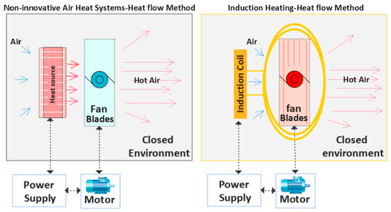
Figure 1.
Comparative temperature distribution analysis in conventional and innovative air heating systems.
Electric resistance heaters operate on the principle of Joule heating, also known as resistive heating. When an electric current flows through a material with resistance, like a metal wire or resistor, it encounters resistance, leading to the collision of electrons with atoms in the material [1,6,7]. There are many methods for converting electrical energy into heat for air heating [8,9]. This study focuses on analyzing the applicability of induction heating as a foundational element for an air heating system.
Induction heating technology has revolutionized various applications, offering efficient and precise heating solutions and rapid heating capabilities. It has emerged as a versatile and indispensable technology that has been widely adopted across diverse industries. Its multifaceted applications range from the melting of metals and the heat treatment of components to powering cooking appliances and even enhancing the functionality of medical devices. This innovative heating methodology is at the forefront of technological advancements, driving transformations across various sectors by delivering targeted and energy-efficient heating solutions. It draws upon fundamental principles of physics that have been developed over decades, finding particular effectiveness in heating ferromagnetic materials. Through the utilization of the contactless transmission of energy, induction heating achieves swifter heating while heightening safety measures and optimizing efficiency [10]. These advantages stem from the fundamental process that Michael Faraday discovered: when a metal encounters a time-varying magnetic field, it generates currents, which then cause heating. In the case of ferromagnetic substances, this process incurs eddy current and hysteresis losses. The incorporation of power converters featuring semiconductor switches, such as IGBTs, MOSFETs, and BJTs, enables precise control and further amplifies the merits of this exceptional heating technique in the realm of scientific and engineering research [11,12].
The heating-by-induction technique has numerous applications for both static and moveable metal parts [13,14]. A model of the induction heating process for a moving workpiece relies on three crucial parameters. The first component is the induction circuit, which requires coil design, frequency, current, refrigeration, and air gap control. This optimization assures effective power utilization and the seamless passage of the current and magnetism. The second variable is the workpiece, which is influenced by heating time and the metal’s properties, shape, and thickness. Lastly, the movement of the workpiece during heating is the third important factor [12,14,15,16].
Experiments have been conducted to assess induction heating output loads for air heat exchanger applications, employing diverse configurations intended to provide a sizeable surface area, which is helpful for effective heat transfer between ambient air and solid materials. Nevertheless, it is noteworthy that induction heating still predominantly relies on a stationary heat source [17,18].
Analytical and numerical models provide valuable insights and predictions regarding the behavior of induction heating processes, serving as indispensable instruments for theoretical research and analysis [19,20]. They aid in optimizing the design of induction heating systems and provide insight into how various factors affect heating outcomes.
Previous studies have been conducted involving an analysis of the induction-based heating of moving metal objects using numerical models [16,19,20,21]. These models are based on the solution of coupled Maxwell’s equations for magnetic analysis and Fourier’s equations for thermal analysis. Numerical methods are extensively employed to model induction heating processes, with a primary focus on electromagnetic and thermal calculations. These methodologies encompass the finite element method, the boundary element method, and mixed finite elements. The interplay of electromagnetic, thermal, and mechanical computations is found.
This research aims to explore the idea of heating a moving metal item via electromagnetic coupling and utilizing the generated heat. Understanding the mechanisms involved in heating the moving metal element and transferring the generated heat to the surrounding air, thereby effectively heating the air, will be the primary focus. In addition, the research will investigate the amount of electrical energy necessary to accomplish a predetermined change in air temperature within a specified time period.
2. Description of the Experimental Setup
This experimental setup has three important factors. First, the heart of the system is the induction circuit. Second, we focus on the workpiece, which directly interacts with the induction circuit and produces the desired results. Third, the movement of the workpiece during heating can significantly influence the results [19,20,21] when heating a specific area within a known experimental environment. Table 1 lists the components and measuring instruments (Figure 2), while Figure 1 shows a simple experimental framework for sequential energy transfer.

Table 1.
Components and measuring instruments of the system.
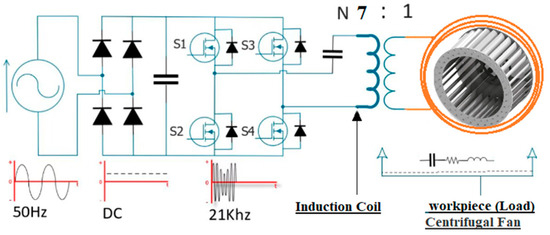
Figure 2.
Key factors in sequential energy transfer and conversion (from AC to DC, to AC) for air heating.
A box with a volume of half a cubic meter was constructed, with the fan positioned inside and the motor placed outside of the box (Figure 3). The design included the implementation of an induction heating circuit, known as a zero-voltage switching (ZVS) circuit. The inductive coil was extended into the interior of the box, with a cylindrical frame consisting of seven coils surrounding the fan within the air gap. Additionally, a sensor for temperature was inserted from the interior into the center of the box.
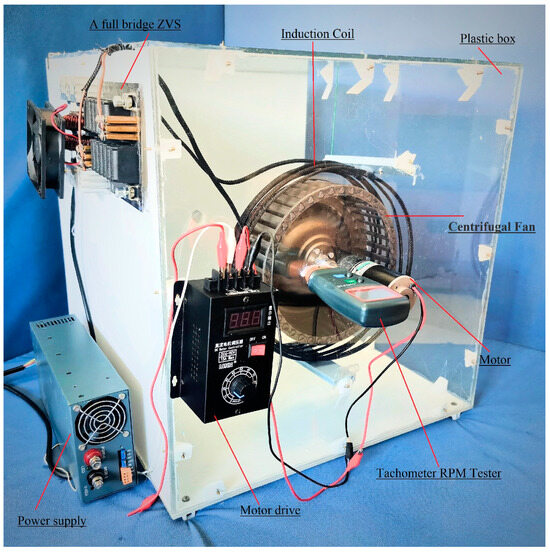
Figure 3.
The experimental prototype.
The temperature of the experimental environment was set at 25 °C. The fan speed was set to 100 revolutions per minute (rpm), and the induction circuit was started. Temperature readings were taken every minute for one hour. This process was repeated ten times, each time increasing the speed by 100 rpm while monitoring the system’s electrical power consumption at each speed.
The collected data were analyzed according to the performance evaluation criteria, as follows: the heat flow of the experimental electromechanical system (Q) is expressed by Equation (1), where (m) represents the mass of air in a volume of half a cubic meter, which equals 0.029 kg. (Cp) is the specific heat capacity of air, and it amounts to 710 joules per gram per degree Celsius. ΔT, on the other hand, signifies the change in temperature.
Q = m · Cp · ΔT
Efficiency in an experimental electromechanical system (η) is measured by the ratio of the useful output (heat) to the initial input (electrical power) in volts (V) and amperes (A), illustrating the input energy being effectively converted and utilized by the system, as follows:
η = (m · Cp · (ΔT))/(V · I)
- A.
- Induction Coil and Workpiece
The technique of ensuring precise and effective heating requires not only aligning the induction coils to the workpiece but also taking into account any potential air gaps [11,22,23, 24,25,26,27,28,29]. When the geometry of the workpiece was complex, numerous specially designed coils were used to heat it uniformly. Figure 4 provides an elucidation of the air gap, accompanied by the dimensions of the file in relation to the workpiece.
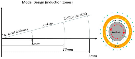
Figure 4.
The coil’s design dimensions with respect to the workpiece and air gap.
- B.
- Induction Generator Model
An implementation of a full-bridge zero-voltage switching (ZVS) series resonant induction generator was introduced to assess and verify the proposed technique. Table 2 provides a detailed overview of the components utilized in the ZVS design.

Table 2.
Components utilized in the ZVS design.
- C.
- Workpiece: Centrifugal Fan
The suitability of metals for induction heating applications and the effectiveness of this method for heating them are highly dependent on their electrical, magnetic, thermodynamic, and structural properties [30,31]. Due to the variations in these properties among various metals and alloys, material selection becomes a critical success factor for induction heating processes. Table 3 provides a detailed overview of the alloy specifications employed in the fabrication of the centrifugal fan. The initial steel microstructure is shown in Figure 5.

Table 3.
The weight percentage composition of alloys (wt %).
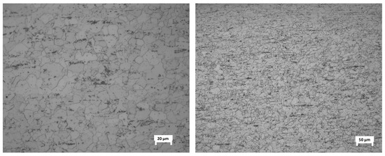
Figure 5.
Initial steel microstructure.
3. Experimental Results
The electromagnetic link between the induction coil and a variable-speed fan has been created, resulting in effective heating of the fan’s metallic components. As an outcome, the higher temperature of the fan blades and their movement will improve heat transmission to the surrounding 500 cm3 of the experimental environment. Figure 6 depicts a graphical depiction of the heat flow study for the system. The system’s infrared thermal images are also displayed in Figure 7, Figure 8, Figure 9 and Figure 10.
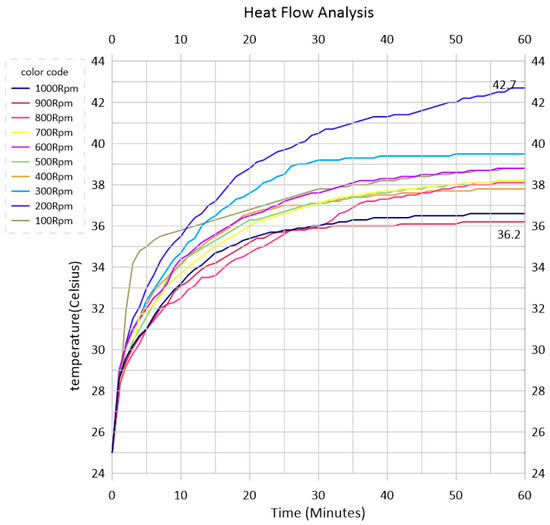
Figure 6.
Rate of air temperature change in a half-cubic-meter closed environment over one hour, showing the induction heating system at different centrifugal fan speeds.
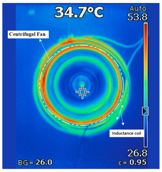
Figure 7.
Thermal impact of a moving fan during induction heating operation.
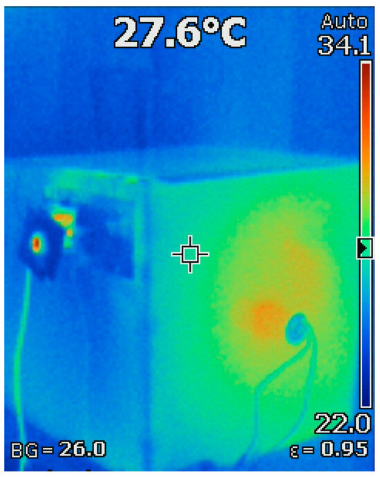
Figure 8.
Exterior thermal impact and experimental model.
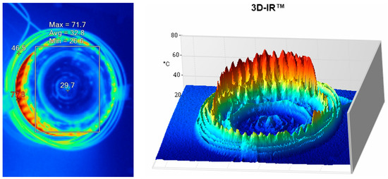
Figure 9.
Thermal impact when the fan remains static and the induction heating circuit is inactive after an all-system shutdown.
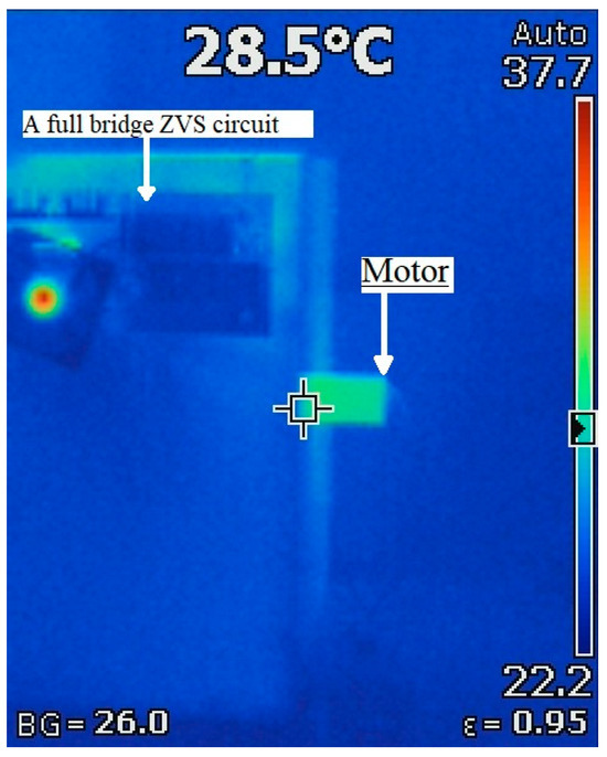
Figure 10.
External thermal effects on the motor and induction circuit after one hour of operation.
The electrical consumption was determined by the measurement of the electric power used by the motor, as seen in Figure 11.
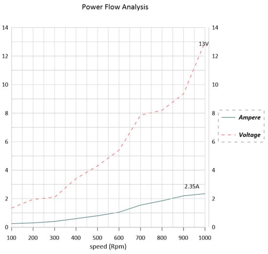
Figure 11.
Variation in electrical power consumption for a DC motor (load) moving the fan at different speeds.
The results encompassed an assessment of the electrical energy consumption by direct current within the proposed system, as depicted in Figure 12.
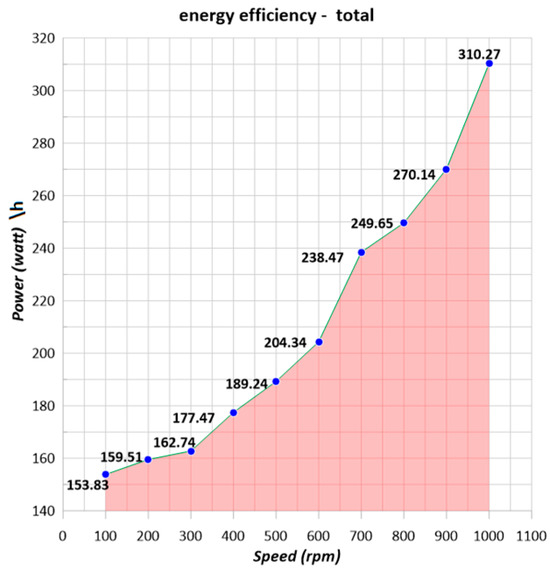
Figure 12.
Total DC consumption of a variable-speed motor and a fixed electrical source in an induction heating circuit.
By keeping the workpiece inside the induction coil, the electrical consumption of the induction circuit remained relatively consistent, even as the speed of the workpiece varied during the experiment. It consistently consumed 18.5 volts and 7.5 amperes.
The applied external power is shown in Figure 13. while the results of the calculations regarding the resulting heat flux of the experimental electromechanical system are shown in Figure 14, and a comparison between them is shown in Figure 15. The system efficiency factor was determined at various rotational speeds, as illustrated in Figure 16.
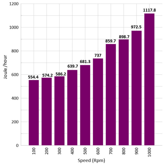
Figure 13.
Applied external power at various rotational speeds.
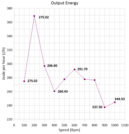
Figure 14.
Resulting heat flux energy in the experimental electromechanical system.
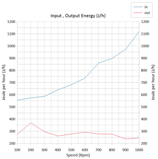
Figure 15.
The resulting heat flux in the experimental electromechanical system and a comparison with an applied external power system.
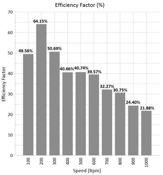
Figure 16.
System efficiency factors at different rotational speeds.
4. Discussion
The proposed approach of utilizing induction heating technology with moving metal parts for the purpose of heating the air via dispersal was found to be successful in achieving the desired outcomes in the experiment.
The study involved examining a range of rotational speeds, spanning from 100 revolutions per minute (rpm) to 1000 rpm, as illustrated in Figure 6. Importantly, the experiment focused solely on the effects of rotational speed and did not introduce alterations to the metal composition of the moving workpiece, variations in the electrical input source for the circuit, or adjustments to the distance (the air gap) between the induction coil and the workpiece. Furthermore, the study did not aim to investigate fluctuations in pressure within the enclosed environment.
The highest observed rate of temperature change within the controlled experimental setting was 17.7 degrees Celsius per hour, which corresponds to the 200-rpm condition set in Figure 4, and yielded an efficiency factor of 64.15% (Figure 16). This temperature change was achieved with an estimated electrical consumption of 159.51 watts, derived from the direct current power source.
It was observed that the operation of the fan at a lower speed led to a significant and rapid rise in the temperature of the fan’s body. Nevertheless, it was observed that the fan had difficulties efficiently dispersing the air within the experimental setting while operating at very low velocities, as indicated by the 100-rpm data point in Figure 6. In contrast, the fan’s operation at a notably elevated velocity resulted in a substantial augmentation of air circulation, accompanied by a diminished influence of inductive currents on the fan’s structure, as demonstrated by the performance at 1000 rpm.
The measurement of electrical consumption was based on an assessment of the electric power utilized by the motor, as illustrated in Figure 12.
The use of a closed box for the experiment (Figure 3) offered several distinct advantages. Firstly, the box’s uniform dimensions ensured excellent visibility, facilitating clear observations. Additionally, the presence of a transparent panel allowed for unobstructed monitoring of the experiment. Furthermore, the enclosed nature of the box restricted the region from which temperature measurements of the rapidly moving air could be taken.
In this experiment, a full-bridge zero-voltage switching (ZVS) circuit was chosen due to its widely acknowledged adaptability and versatile applications in various domains (see the list of components in Table 1), as documented in references [21,22]. Its significance lies in its ability to establish a resonant frequency that coincides with the operating frequency of the ZVS inverter, thereby facilitating efficient and near-zero-voltage switching, minimizing switching losses, and enhancing the overall system efficiency.
This circuit also functions as an energy storage and transfer mechanism, ensuring optimal power transfer to the load, impedance matching, enhanced stability, and high energy conversion efficiency, all of which are essential for achieving stable heating processes [22]. The selection of this circuit was motivated by its flexibility within the context of this experiment.
An essential aspect to highlight is that the induction coil design was meticulously engineered to precisely direct the inductive field towards the fan. This careful design ensured that there was no undesired heating of the fan’s driving motor or any adverse impact on the internal magnetic poles of the motor. Furthermore, it is noteworthy that all components of the experiment maintained thermal stability except for the fan, which required heating, as illustrated in Figure 10.
This method of transferring heat to the air for heating, using a metal body with inductive energy to generate heat and kinetic energy to enhance heat transfer (refer to Figure 1), differs from traditional methods in which the heat exchange source is a stationary object [23].
Industrial design challenges encompass the modeling of components and devices that interact with physical fields, as seen in induction heating systems, the interplay of electromagnetic and thermal factors, and evolving boundary conditions over time [24,25].
A closed system has numerous driving factors, such as area, temperature, and energy. This is a common design in thermal systems [26,27,28,29,30]. These many aspects provide opportunities for the advancement of this innovative technology, which has the potential to emerge as a viable replacement for contemporary heating techniques.
5. Conclusions
The application of induction heating as a foundational element for an air heating system demonstrates promise. Presenting a modern application for air heating, this research explored the mechanisms involved in heating a moving metal element via electromagnetic coupling and transferring the generated heat to the surrounding air to heat it.
The experimental results indicate that the proposed technique can achieve substantial temperature changes within a controlled environment. The highest observed temperature change rate was 17.7 degrees Celsius per hour, with an efficiency factor of 64.15%.
It was observed that the operation of the fan at a lower speed led to a significant and rapid rise in the temperature of the fan’s body. Nevertheless, the fan’s operation at a notably elevated velocity resulted in a substantial augmentation of air circulation, accompanied by a diminished influence of the inductive currents on the fan’s structure.
The experimental findings, combined with various factors, influence the overall efficiency of the experimental system. These factors include the intensity of the inductive field emitted by the induction circuit toward the induction coil, the design and number of turns of the inductor, the air gap between the coils and the fan, the properties of the alloy materials composing the fan, and the size of the environment to be heated. This research paves the way for the further exploration and development of this innovative technology. With continued refinement, induction-based air heating systems may emerge as a viable and energy-efficient alternative to conventional heating techniques, offering substantial benefits in various applications from industrial processes to everyday household heating needs.
Author Contributions
G.M. was the lead author and was responsible for the experimental system design. Y.C. was the research supervisor. All authors have read and agreed to the published version of the manuscript.
Funding
The authors received no special funding for the study.
Data Availability Statement
Data are available on request from the authors.
Acknowledgments
Part of this research was conducted with the support of Tianjin University. The authors would like to express our gratitude for their support. I would also like to express my gratitude to Yanbo Che, my research supervisor, as well as Almonzer Nooraldaim, Antoniuk Kateryna, Zhang Tan, Meng Zhida and the Sudanese Researchers Group for their dedicated efforts and support. All authors reviewed the manuscript draft and revised it critically for intellectual content.
Conflicts of Interest
The authors declare no conflict of interest.
References
- McQuiston, F.C.; Parker, J.D.; Spitler, J.D.; Taherian, H. Heating, Ventilating, and Air Conditioning: Analysis and Design; John Wiley & Sons: Hoboken, NJ, USA, 2023. [Google Scholar]
- Haines, R.W.; Hittle, D.C. Control Systems for Heating, Ventilating, and Air Conditioning; Springer Science & Business Media: Berlin/Heidelberg, Germany, 2006. [Google Scholar]
- Gates, R.S.; Casey, K.D.; Xin, H.; Wheeler, E.F.; Simmons, J.D. Fan assessment numeration system (FANS) design and calibration specifications. Trans. ASAE 2004, 47, 1709–1715. [Google Scholar] [CrossRef]
- Nellis, G.; Klein, S. Heat Transfer; Cambridge University Press: Cambridge, UK, 2008. [Google Scholar]
- Kreider, J.F. (Ed.) Handbook of Heating, Ventilation, and Air Conditioning; CRC Press: Boca Raton, FL, USA, 2000. [Google Scholar]
- Cosnier, M.; Fraisse, G.; Luo, L. An experimental and numerical study of a thermoelectric air-cooling and air-heating system. Int. J. Refrig. 2008, 31, 1051–1062. [Google Scholar] [CrossRef]
- Rolsma, B. Heat transfer aspects of electric heating. Trans. Am. Inst. Electr. Eng. Part II Appl. Ind. 1961, 80, 28–33. [Google Scholar] [CrossRef]
- Lake, A.; Rezaie, B.; Beyerlein, S. Review of district heating and cooling systems for a sustainable future. Renew. Sustain. Energy Rev. 2017, 67, 417–425. [Google Scholar] [CrossRef]
- Bell, L.E. Cooling, heating, generating power, and recovering waste heat with thermoelectric systems. Science 2008, 321, 1457–1461. [Google Scholar] [CrossRef] [PubMed]
- Lucía, O.; Maussion, P.; Dede, E.J.; Burdío, J.M. Induction heating technology and its applications: Past developments, current technology, and future challenges. IEEE Trans. Ind. Electron. 2013, 61, 2509–2520. [Google Scholar] [CrossRef]
- Semiatin, S.L. Elements of Induction Heating: Design, Control, and Applications; ASM International: Almere, The Netherlands, 1988. [Google Scholar]
- Sharma, G.K.; Pant, P.; Jain, P.K.; Kankar, P.K.; Tandon, P. On the suitability of induction heating system for metal additive manufacturing. Proc. Inst. Mech. Eng. Part B J. Eng. Manuf. 2021, 235, 219–229. [Google Scholar] [CrossRef]
- Zhang, X.B.; Yang, Y.L.; Liu, Y.J. The numerical analysis of temperature field during moveable induction heating of steel plate. J. Ship Prod. Des. 2012, 28, 73–81. [Google Scholar] [CrossRef]
- Zhang, X.; Chen, C.; Li, J.; Liu, Y. The numerical study of steel plate forming by moveable induction heating considering the plate edge shrinkage. J. Ship Prod. Des. 2017, 33, 166–177. [Google Scholar] [CrossRef]
- Milošević-Mitić, V.; Maneski, T.; Andjelić, N.M.; Milović, L.; Petrović, A.S.; Gacesa, B.M. Dynamic temperature field in the ferromagnetic plate induced by moving high frequency inductor. Therm. Sci. 2014, 18, S49–S58. [Google Scholar] [CrossRef]
- Shokouhmand, H.; Ghaffari, S. Thermal analysis of moving induction heating of a hollow cylinder with subsequent spray cooling: Effect of velocity, initial position of coil, and geometry. Appl. Math. Model. 2012, 36, 4304–4323. [Google Scholar] [CrossRef]
- Unver, U. Efficiency analysis of induction air heater and investigation of distribution of energy losses. Tehnički Vjesnik 2016, 23, 1259–1267. [Google Scholar]
- Thepsatitsilp, K.; Boonpeang, W.; Saeung, P.; Pukseesang, N.; Thongsopa, C. Experiment and design a suitable induction heating for air heat exchanger application. In Proceedings of the 2017 Asia-Pacific International Symposium on Electromagnetic Compatibility (APEMC), Seoul, Republic of Korea, 20–23 June 2017; IEEE: Piscataway, NJ, USA, 2017; pp. 161–163. [Google Scholar]
- Li, F.; Li, X.; Zhu, T.; Rong, Y. Numerical simulation of the moving induction heating process with magnetic flux concentrator. Adv. Mech. Eng. 2013, 5, 907295. [Google Scholar] [CrossRef]
- Bay, F.; Labbé, V.; Favennec, Y.; Chenot, J.L. A numerical model for induction heating processes coupling electromagnetism and thermomechanics. Int. J. Numer. Methods Eng. 2003, 58, 839–867. [Google Scholar] [CrossRef]
- Shao, S.; Chen, H.; Wu, X.; Zhang, J.; Sheng, K. Circulating current and ZVS-on of a dual active bridge DC-DC converter: A review. IEEE Access 2019, 7, 50561–50572. [Google Scholar] [CrossRef]
- Sugimura, H.; Muraoka, H.; Ahmed, T.; Chandhaket, S.; Hiraki, E.; Nakaoka, M.; Lee, H.W. Dual mode phase-shifted ZVS-PWM series load resonant high-frequency inverter for induction heating super heated steamer. J. Power Electron. 2004, 4, 138–151. [Google Scholar]
- Peng, Q.; Du, Q. Progress in heat pump air conditioning systems for electric vehicles—A review. Energies 2016, 9, 240. [Google Scholar] [CrossRef]
- Di Barba, P.; Mognaschi, M.E.; Lowther, D.A.; Dughiero, F.; Forzan, M.; Lupi, S.; Sieni, E. A benchmark problem of induction heating analysis. Int. J. Appl. Electromagn. Mech. 2017, 53, S139–S149. [Google Scholar] [CrossRef]
- Solin, P.; Dolezel, I.; Karban, P.; Ulrych, B. Integral Methods in Low-Frequency Electromagnetics; John Wiley & Sons: Hoboken, NJ, USA, 2009. [Google Scholar]
- Ozgener, O.; Ozgener, L.; Goswami, D.Y. Experimental prediction of total thermal resistance of a closed loop EAHE for greenhouse cooling system. Int. Commun. Heat Mass Transf. 2011, 38, 711–716. [Google Scholar] [CrossRef]
- Ozgener, L. A review on the experimental and analytical analysis of earth to air heat exchanger (EAHE) systems in Turkey. Renew. Sustain. Energy Rev. 2011, 15, 4483–4490. [Google Scholar] [CrossRef]
- Aktaş, M.; Şevik, S.; Özdemir, M.B.; Gönen, E. Performance analysis and modeling of a closed-loop heat pump dryer for bay leaves using artificial neural network. Appl. Therm. Eng. 2015, 87, 714–723. [Google Scholar] [CrossRef]
- Tavakoli, M.H.; Ojaghi, A.; Mohammadi-Manesh, E.; Mansour, M. Influence of coil geometry on the induction heating process in crystal growth systems. J. Cryst. Growth 2009, 311, 1594–1599. [Google Scholar] [CrossRef]
- Khot, V.M.; Salunkhe, A.B.; Thorat, N.D.; Phadatare, M.R.; Pawar, S.H. Induction heating studies of combustion synthesized MgFe2O4 nanoparticles for hyperthermia applications. J. Magn. Magn. Mater. 2013, 332, 48–51. [Google Scholar] [CrossRef]
- Anila, I.; Lahiri, B.B.; John, S.P.; Mathew, M.J.; Philip, J. Preparation, physicochemical characterization, and AC induction heating properties of colloidal aggregates of ferrimagnetic cobalt ferrite nanoparticles coated with a bio-compatible polymer. Ceram. Int. 2023, 49, 15183–15199. [Google Scholar] [CrossRef]
Disclaimer/Publisher’s Note: The statements, opinions and data contained in all publications are solely those of the individual author(s) and contributor(s) and not of MDPI and/or the editor(s). MDPI and/or the editor(s) disclaim responsibility for any injury to people or property resulting from any ideas, methods, instructions or products referred to in the content. |
© 2023 by the authors. Licensee MDPI, Basel, Switzerland. This article is an open access article distributed under the terms and conditions of the Creative Commons Attribution (CC BY) license (https://creativecommons.org/licenses/by/4.0/).