Abstract
Demand for biofuels will likely increase, driven by intensifying obligations to decarbonize aviation and maritime sectors. Sustainable biomass is a finite resource, and the forest harvesting level is a topic of ongoing discussions, in relation to biodiversity preservation and the short-term role of forests as carbon sinks. State-of-the-art technologies for converting lignocellulosic feedstock into transportation biofuels achieves a carbon utilization rate ranging from 25% to 50%. Mature technologies like second-generation ethanol and gasification-based processes tend to fall toward the lower end of this spectrum. This study explores how electrification can enhance the carbon efficiency of biorefinery concepts and investigates its impact on energy, economics and greenhouse gas emissions. Results show that electrification increases carbon efficiency from 28% to 123% for gasification processes, from 28% to 45% for second-generation ethanol, and from 50% to 65% for direct liquefaction processes. Biofuels are produced to a cost range 60–140 EUR/MWh-biofuel, depending on the chosen technology pathway, feedstock and electricity prices. Notably, production in electrified biorefineries proves cost-competitive when compared to pure electrofuel (E-fuels) tracks. Depending on the selected technology pathway and the extent of electrification, a reduction in GHG emissions ranging from 75% to 98% is achievable, particularly when powered by a low-carbon electricity mix.
1. Introduction
The transition to sustainable materials, chemicals and energy is highly likely to increase the demand for biomass resources in the near and long-term. Forest-based residues and by-products are promising feedstock categories in many countries with a large forest industry, such as Sweden, but despite a comparatively large potential, they are, like all biomass, a limited resource, constrained by consideration to, e.g., biodiversity and forests as a carbon sink. Hence, efficient conversion of biomass resources into final products is vital to maximize their contribution to a sustainable society. Biorefineries are expected to play an important role in achieving sustainability in the transport sector, thereby facilitating the transformation into a circular bioeconomy globally [1] and notably in a Nordic context [2].
Commercial technologies for processing lignocellulosic feedstock into biofuels often have low carbon conversion, referring to the fraction of carbon that ends up in products. For example, typical carbon efficiency to biofuels via gasification-based technology (Fischer–Tropsch, methanol or methane) is 30–40% [3,4,5,6], and for second generation ethanol 27–30% [7,8,9]. These tracks produce significant amounts of concentrated biogenic CO2 emphasizing the large flow of carbon atoms in the feedstock that leave the system as non-products. Concentrated biogenic CO2 streams can provide opportunities for bio-CCS, in a negative emissions concept, or bio-CCU, where it is converted into biofuels and chemicals increasing the per life cycle use of carbon atoms [10]. Direct liquefaction technologies, such as hydrothermal liquefaction [11,12] and fast pyrolysis [11,13] have relatively better carbon conversion efficiency, reaching typically about 50%.
As the demand for a limited biomass resource continues to rise in the future, technologies that enable the maximal utilization of biogenic carbon will grow in importance. However, evaluating carbon performance should extend beyond assessing a technology’s capacity to directly utilize a given feedstock. It should also consider its ability to establish connections with other renewable energy forms, such as heat, electricity and hydrogen. These interconnections can empower technology pathways to achieve increased productivity and superior environmental performance while utilizing the same quantity of feedstock. Therefore, conducting a comprehensive system-level assessment of all potential technology pathways is crucial. Such an evaluation allows for the mapping of their performances from carbon, economic and greenhouse gas perspectives.
The inherent carbon efficiency limitations observed in biomass conversion technologies primarily stem from specific challenges encountered in the production of biofuels [10,14]. These challenges can be addressed or alleviated through the incorporation of various forms of electrical energy within the conversion process:
- Biomass typically exhibits a hydrogen-to-carbon atomic ratio ranging from 1 to 1.5, whereas hydrocarbon-based fuels typically possess a ratio 2. This discrepancy implies that carbon atoms are inevitably lost unless an alternative balancing method is employed, such as the addition of hydrogen.
- Biomass inherently contains a substantial amount of oxygen, which must be eliminated to varying degrees depending on the desired product. This elimination often occurs in the form of CO2 or H2O. The removal of oxygen as CO2 results in carbon losses, while its removal as water exacerbates the hydrogen-carbon imbalance mentioned in the previous point. In many conversion technologies, hydrogen is utilized, either directly or indirectly, to facilitate the removal of oxygen.
- Several conversion technologies, including gasification and steam reforming, operate at high temperatures, with energy supplied through the combustion of the biogenic feedstock itself or intermediary substances. This high-temperature operation can lead to energy losses.
From the above, supply of hydrogen and heat can mitigate many of the factors limiting carbon conversion. Water electrolysis is an obvious option for hydrogen supply, while either direct (e.g., resistive) heating or heat pumps are options for a heat supply that uses electrical energy, depending on the temperature of the other process requirement.
Several studies have looked at a range of strategies for production of sustainable transport fuels that relates to the issues discussed above, including configurations producing drop-in biofuels [15,16,17], to hydrogen-assisted biofuels [10,14,18,19,20,21] and electrofuels (E-fuels) [22,23]. Advanced biomass-to-liquid or -gas (BtL or BtG) concepts so far focused on the contribution of electricity via electrolysis as a source of hydrogen and oxygen streams, which both magnify biofuel productivity and reduce oxygen utility requirements [10,18]. Previous research has explored technologies that integrate the use of electricity benefit substantially, e.g., the European potential for gasification-based production [14] and BtL potential to defossilize the Danish transport sector [22]. Flexibility is frequently a topic of discussion when it comes to gasification applications, as it allows for seamless integration with intermittent electricity systems [24,25].
However, previous research has often discussed various aspects and technical options for different production technologies in a fragmented manner, making it challenging to conduct direct comparisons. There is currently a lack of both a comprehensive overview of the technical opportunities available for integrated electrification in biofuel production and a generic analysis of these possibilities. This study seeks to bridge this gap by providing a comprehensive performance assessment for the electrification of biorefinery concepts, encompassing various conversion pathways. Such an assessment can be instrumental in guiding strategic decision-making in areas such as policy development, technology advancement and the execution of commercial projects. This study also expands on the contribution of electricity in biorefinery concepts through integrated measures using upcoming technologies (e.g., electrified steam reformer [26]), direct heating (e.g., electric boiler, resistance heated reactor surfaces) or indirect heating such as vapor recompression heat pumps to produce low temperature heat for evaporation or distillation [27].
The primary goal is to offer a comprehensive perspective on the opportunities, advantages and disadvantages associated with the integration of electrification in biofuel production. More specifically, this study seeks to investigate the following aspects:
- the feasibility of integrating electrification within diverse lignocellulosic biofuel value chains, assessing both their technical and commercial relevance in the present and in the short to medium term.
- the potential consequences of integrating electrification on production capabilities, carbon efficiency and resource utilization within various biofuel value chains.
- the possible effects of integrating electrification on production expenses and greenhouse gas performance across different biofuel value chains. Additionally, it aims to analyze which electrification strategies yield the greatest benefits, including improved resource efficiency.
The contents of this paper are organized as follows. Section 2 describes the motivation, selection criteria of the biofuel tracks studied in detail and evaluation methodology, providing the sources including a brief description and reference configuration for each track. In addition, Section 2 documents electrification strategies implemented, indicating electrification enabling technologies involved in each configuration of a given biofuel production track. Section 3 presents the results, including discussions highlighting the main takeaway messages. The main conclusions drawn are recapitulated in Section 4.
2. Material and Methods
This section describes the evaluation framework and documents the configurations and plant capacities for the biofuel technology tracks studied. Figure 1 shows a flow diagram of the evaluation framework. Table 1 summarizes the list of biofuel production pathways studied in detail in this work. An initial screening phase was used to arrive at this prioritization, based on multiple selection criteria:
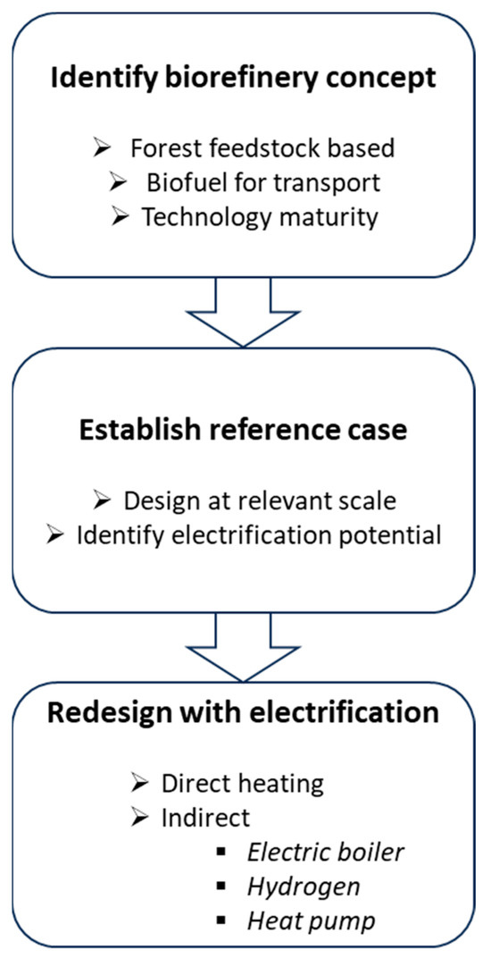
Figure 1.
Evaluation framework.

Table 1.
Technology tracks studied in detail.
- Feedstock is primarily lignocellulosic forest residue but also agricultural residue;
- Nordic region production potential and the corresponding suitable technologies;
- Biofuel as the primary product, primarily for road transport but also aviation fuel;
- Technologies considered should be available at the commercial level or have the potential to be commercially deployed at scale at the latest by 2030.
2.1. Biofuel Production Tracks
Figure 2 shows the reference case process configuration of the technology tracks, feedstock, biofuel products and other tradable coproducts. A brief description of each technology track under reference case configuration and capacity is presented below. These non-electrified technologies are denoted reference cases to differentiate them from the electrified versions. Separate process flow diagrams including the process conditions of major units are presented in the Supplementary Material. For the gasification-based tracks, gasification technologies and syngas-upgrading technologies are described separately and can be combined into the tracks in Table 1 as indicated in Figure 2.
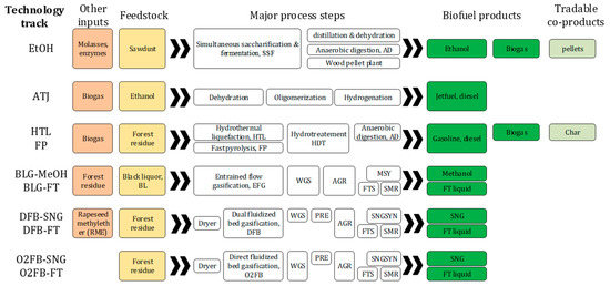
Figure 2.
Reference case configurations of the conversion pathways studied in detail, WGS—water gas shift, AGR—acid gas removal, MSY—methanol synthesis, FTS—Fischer–Tropsch synthesis, SMR—steam reformer, PRE—premethanation, SNGSYN—synthetic natural gas synthesis.
EtOH: The reference ethanol plant utilizes the Simultaneous Saccharification and Fermentation (SSF) pathway [7] and has a capacity to process 56 ton/h (137 MW HHV) of sawdust with a moisture content of 55%. This process results in the production of 5.6 ton/h (48 MW HHV) of ethanol with a purity of 99.9% volume. Additionally, the process generates biogas and wood pellets from distillation stillage and solid residues, using an anaerobic digester and a pellet plant, respectively. Initial treatment of the sawdust involves the use of saturated steam at pressures of 20 and 4 bars, which is mixed directly with the feedstock. Additional steam at 4 and 20 bars is required for heating in the distillation re-boiler during the upgrading process and for preheating the drying air in the lignin pellet dryer, a crucial step for reducing the pellet moisture content to 12%. In this reference scenario, the facility meets its steam requirements internally by burning solid residues from the anaerobic digester and a portion of lignin in an integrated Combined Heat and Power (CHP) plant. This CHP plant operates within a Rankine cycle, with a maximum cycle pressure of 90 bars and a temperature of 470 °C. The facility itself consumes 3.6 MW of electricity, and in the reference case, this electricity was supplied by the CHP plant.
ATJ: Sustainable aviation fuel (SAF) is becoming increasingly important among renewable liquid fuels. ATJ (Alcohol-to-Jet) technology is acknowledged as a short-term solution to reduce emissions in the aviation sector [28]. ASTM certification for SAF derived from isobutanol was approved in 2016 and for ethanol in 2018 [29]. According to the International Energy Agency (IEA), ATJ is expected to reach commercialization by 2025 [29]. In the reference case, the ATJ facility is designed to have a capacity to produce 104 MW HHV biofuels, consisting of 92 MW jet fuel range and 12 MW diesel range, using 113 MW HHV of ethanol. To achieve economies of scale, multiple lignocellulosic ethanol plants are assumed to supply the common ATJ facility. The ATJ process involves several stages, including dehydration, oligomerization, hydrogenation and fractionation. First, ethanol is dehydrated into ethylene, resulting in a mass reduction of approximately 45%. Depending on the specific conditions and design performance, a combination of distillation, liquid–liquid separation and molecular sieves may be used to eliminate water content. Oligomerization, the process of converting ethylene into longer hydrocarbon chains typically found in jet fuels (ranging from C9 to C16), is a technology already established in the petrochemical industry. Ethylene oligomerization generates a distribution of carbon chains between C4 and C20+, with the highest selectivities for C10 and C12 range. In the final stage, the olefins produced are hydrogenated to saturate the double bonds formed during oligomerization. Ensuring that the product is sufficiently saturated is crucial to achieving the desired fuel properties, including low reactivity [28]. Hydrogen needed for the process is partially obtained by recycling unreacted hydrogen gas from the product stream. In the reference case, the heat requirement for the dehydration and oligomerization processes is met through the combustion of biogas.
HTL: the reference configuration and the mass and energy balances of the HTL process were adopted from [11]. The process begins by softening ground biomass using hot water from the process to create a pumpable slurry feed containing approximately 8% solids. This slurry is then pumped to the HTL reaction pressure level, which is 20.4 MPa, and subsequently preheated to 300 °C by exchanging heat with the hot effluent exiting the HTL reactor. Inside the HTL reactor, the hot biomass slurry undergoes conversion. The resulting effluent from this process contains solid waste, primarily composed of inorganic solids like ash, which is separated from the hot HTL effluent. The effluent from the reactor is then cooled and separated into three phases: a gas phase, bio-oil and an aqueous phase consisting mainly of water with some dissolved organics. The bio-oil is directed to the upgrading process, while a majority of the aqueous phase is recycled back to the feedstock preparation step. A portion of this aqueous phase is discharged to wastewater treatment. Alternatively, the organic content in the purged aqueous phase can be subject to anaerobic treatment to produce biogas. The gas phase is sent to a hydrogen plant to generate hydrogen, which is used in the upgrading process. The crude bio-oil is subjected to hydrotreating, either alone or in combination with hydrocracking, to remove a significant portion of the oxygen present in the bio-oil. The upgraded hydrocarbon product is then stabilized through cooling and distillation to produce liquid fuels, including gasoline, diesel and heavy oil fractions, based on their boiling point ranges. It is worth noting that due to the limited scope of this experimental work, the hydrocracking step has not been demonstrated in the reference process. Therefore, the assumption in this work is that only hydrotreating is employed for upgrading. In this setup, the HTL plant has a feedstock capacity of 94 MWHHV, which is converted into 68 MWHHV of biofuel products, consisting of 49 MW of gasoline, 11 MW of diesel and 8 MW of heavy fraction.
FP: the reference case configuration and data were sourced from [13]. However, the plant capacity considered in this study was adjusted to match the commercial pyrolysis plants developed by BTG bioliquids®, which are currently operational in the Netherlands (Empyro Hengelo, Hengelo, the Netherlands), Finland (Green Fuel Nordic, Joensuu, Finland) and Sweden (Pyrocell, Gävle, Sweden). The pyrolysis plant has a feedstock capacity of 27 MWHHV, and after the pyrolysis process and subsequent oil hydrotreatment upgrading, it is converted into hydrocarbon products with an energy equivalent of 20 MW HHV. These products include 10 MW of gasoline, 7 MW of diesel and 3 MW of heavy fraction. The process begins with forest residue containing 50% moisture, which is dried to 8–10% moisture using a conventional belt dryer. Various heat sources such as steam, flue gas, hot water and electricity can be used for this purpose. The dried and ground biomass, reduced to particles <5 mm in size using a highly efficient grinder with an energy requirement of 14 kWh/ton [13], enters a circulating fluidized bed reactor. Inside the reactor, it is rapidly heated to 520 °C under atmospheric pressure in an oxygen-free environment, where it mixes with hot fluidized sand and undergoes a reaction to produce pyrolysis gases and char. The reactor is heated with hot sand from the char combustor. The char is partially separated by a cyclone, and a portion of it is directed to the combustion chamber, where the recirculating sand is heated to approximately 680 °C. The remaining char is combusted to provide process energy. In a subsequent stage, the pyrolysis gases are condensed into a liquid fraction known as bio-oil, while the non-condensable fraction is used to fluidize the pyrolysis process. The bio-oil produced in the fast pyrolysis process is unstable and cannot be directly blended with conventional fossil fuels. Therefore, the bio-oil undergoes hydrotreatment, where hydrogen is employed to upgrade the unstable oil by removing oxygen. The upgraded bio-oil is then distilled to obtain hydrocarbon fractions with boiling points in the gasoline, diesel and heavy range.
BLG: biorefinery concepts involving black liquor (BL) gasification are essentially integrated at a pulp mill, e.g., [30,31]. BL, a byproduct stream of chemical pulping, consisting of inorganic components (cooking chemicals), organic components (lignin and fiber residues) and water. BL has typical elemental composition, wt. % dry, C 33.6, H 3.58, N 0.1, S 4.6, Cl 0.03, Na 17.06, K 1.23, O 39.8 and calorific value 13 MJ/kg dry BL. The underlying assumption with BL gasification is that the mill must be able to operate as usual. Rerouting part of the BL for gasification mainly impacts the steam balance of the mill, and any deficit in steam requirement of the pulping process must be compensated by using excess steam produced at the integrated biofuel plant and importing additional biomass to the biomass boiler, as depicted in Figure 3. Power generation is not necessarily maintained at reference value since most of the steam is not compensated at a pressure and temperature high enough to allow power production.
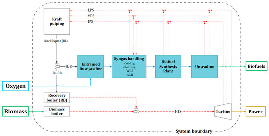
Figure 3.
Integrated BLG-based biofuel process system boundary.
The pulp mill considered for integrating the BLG process has a daily production capacity of 2000 ADt (air dried tonne) of pulp and was simulated as a modern facility using softwood as its primary feedstock [32]. This capacity is approximately equivalent to the size of the largest operational mill in Scandinavia today, producing around 3760 tBLS (tonnes of BL solid content) per day. During regular operation, the pulp mill generates surplus steam by burning BL in its recovery boiler. This excess steam is utilized for power generation through a condensing turbine, making the mill, when operating independently, a net exporter of electricity, contributing about 50 MWel to the grid. Additionally, some of the bark generated when debarking incoming biomass is used to fuel the lime kiln. The remaining bark can be employed in two ways: it can either be combusted in a biomass boiler to generate additional high-pressure steam (HPS) for increasing net electricity export, or it can be sold as a solid fuel to other industries.
Entrained flow BLG has undergone a successful pilot-scale demonstration at a facility with a thermal capacity of 3 MWth, conducted for a duration of over 25,000 h in Piteå, Sweden [4]. The BLG mass and energy balance data utilized for the reference case are based on measurements taken at this pilot plant [4] and scaled-up technoeconomic evaluations [33]. The BLG reactor uses oxygen as a gasification agent and runs at 30 barg and 1050 °C. The raw gas produced in the upper section of the reactor is rapidly cooled at the reactor’s bottom to recover pulping chemicals in the form of green liquor, which is subsequently returned to the chemical recovery loop of the pulp mill. As it exits the BLG unit, the raw gas is saturated at approximately 210 °C. The raw gas is cooled in a counter-current condensation process, reaching a temperature of 40 °C. During this cooling process, low-pressure steam (LPS) and hot water are generated from the reclaimed heat.
The BLG reactor is oxygen-blown operated at 30 barg and 1050 °C. The raw gas generated in the upper section of the reactor is quenched at the bottom of the reactor to recover pulping chemicals in the form of green liquor, which is sent back to the chemical recovery loop of the pulp mill. The gas emerges from the BLG unit fully saturated at approximately 210 °C. It is subsequently cooled down to 40 °C in a counter-current condensation process. During this cooling step, low-pressure steam (LPS) at a range of 3–5 bars and hot water are generated using the reclaimed heat. In the BLG reference scenarios, it is assumed that a plant with a capacity of 338 MWHHV (equivalent to 60% of the available BL capacity) is utilized for gasifying raw gas. The raw gas has a molar composition roughly, vol. % dry, H2 33, CO 33, CO2 31, CH4 1, H2S 1 and traces of impurities such as COS, N2, ammonia etc.
DFB: This technology is suitable for systems aiming at co-production of heat, power and/or liquid biofuels. DFB employs two interconnected sections, a steam-blown gasification zone and an air-blown combustion zone [15]. The bed material circulates between the sections transporting heat from the combustor to the gasifier. Such configuration presents design flexibility to prioritize desired products among heat, electricity or syngas. DFB has been proven at a commercial level for production heat and power, e.g., Senden, Oberwart and Gussing. The GoBiGas plant in Gothenburg, Sweden [3] demonstrated 20 MWLHV SNG production from forest feedstock based on DFB concept. The reference case configuration and data used in this work are inspired by the GoBiGas performance [3] and applied to a CHP-integrated case. The product gas after primary cleaning, i.e., sequential removal of particulates and scrubbing of tars, typically has a molar composition, vol. %, H2 39, CO 19, CO2 23, CH4 7.4, H2O 9.5, C2Hx 2 and traces of impurities such as benzene, H2S, COS, N2, HCN, ammonia etc.
O2FB: in direct fluidized bed gasification, biomass is converted into syngas using steam and oxygen under atmospheric or pressurized conditions at temperature in the range 850–950 °C. The operating pressure is often matched to the downstream requirements. This technology is mature with commercial installation developed by Andritz Carbona in Skive, Denmark and a demonstration plant at GTI in Chicago, USA [6]. The performance and scale of the O2FB gasifier is based on the process design laid out in the BioMeet project [34]. The raw gas from the gasification train has a molar composition, vol. % dry, H2 30, CO 30, CO2 33, CH4 7 and traces of impurities such as H2S, N2, benzene etc.
Synthetic natural gas synthesis (SNGSYN): the syngas from gasification needs to be conditioned before the SNGSYN mainly by water gas shift (WGS), premethanation (PRE) and amine scrubbing-based acid gas removal (AGR). The premethanation reactor, depending on the conditions and catalyst used, promotes as much methanation of CO2 as possible prior to the AGR, where CO2 and other impurities are removed. Stoichiometrically, the syngas entering SNGSYN requires a molar ratio of H2/CO = 3. To avoid the need for additional CO2 removal in the final stage, the syngas entering SNGSYN must contain enough hydrogen to ensure complete methanation of CO and CO2.
Methanol synthesis (MYS): for optimal conversion to methanol, the syngas entering the MSY reactor should satisfy the so-called Module (M) 2.05, evaluated based on molar concentrations according to the expression M = [H2 − CO2]/[CO + CO2]. The raw gas should pass through multiple processes prior to MSY, a WGS to enrich H2 content and an AGR to reduce CO2 content and impurities.
Fischer–Tropsch synthesis (FTS): for optimal conversion to FT liquids, the syngas entering FTS reactor must be conditioned to satisfy molar ratio H2/CO~2, from raw gas value about 1 for BLG and O2FB. The DFB is steam-blown and produces syngas rich in H2 content achieving H2/CO about 2 without WGS. Thus, only raw gases from BLG and O2FB need to pass through a WGS to enrich H2 content for optimal FTS. AGR is, however, required by all gasification technologies to reduce CO2 content and impurities. To increase FT yield, light gases C1 to C4 generated during FTS may be reformed into H2 and CO components in a steam reformer (SMR) and mixed with the syngas entering WGS.
Electrofuel tracks (E-fuels): reference pathways have been established to gauge the performance of the hybrid bio-electrofuel concepts under investigation, which involve the conversion of electricity and biogenic CO2 into fuels. Three distinct electrofuel routes are considered, with the aim of producing SNG, methanol and FT liquid. In these pathways, syngas suitable for advanced biofuel synthesis is generated through the reverse water–gas shift (rWGS) process, utilizing hydrogen produced via electrolysis and biogenic CO2. The rWGS process is carefully managed to promote a syngas composition that aligns with the optimal conditions for downstream biofuel synthesis, whether it be SNG, methanol or FT liquid. The production capacities of these electrofuel scenarios are chosen to match the available sources of biogenic CO2 in Sweden, with capacities set at or exceeding 300 kt/y (thousand metric tons per year) as described in reference [33]. To provide some context, 300 kt/y of CO2 corresponds to biofuel production capacities for FT fuels (144 MW HHV), methanol (144 MW HHV) and SNG (201 MW HHV), assuming an annual plant availability rate of 90%. The mass and energy balances for these electrofuel pathways are derived from Brynolf et al.’s [23] work in the 2030 base case scenario. For a more detailed breakdown of assumptions and balances related to E-fuels, please refer to the Supplementary Material.
2.2. Electrification Options
Electricity use in a biorefinery can occur in different forms, direct heating (electric resistance), e.g., resistance-heated steam reformers (eSMR) [26], indirect heating via electrically produced steam, mechanical vapor recompression (MVR) heat pump or hydrogen from electrolysis of water. Depending on the biofuel pathway, suitable electrification option/s are considered, i.e., gasification-based pathways involving syngas benefit from the addition of hydrogen, and pathways with a high demand for process steam benefit from electric boiler and MVR heat pumps, e.g., lignocellulosic ethanol. The complete list of electrified configurations is presented in Table 2, indicating which technologies were evaluated in each configuration.

Table 2.
Reference and electrified configurations studied in detail.
For hydrogen production, two electrolysis technologies that allow compact cell design were considered, proton exchange membrane electrolysis cell (PEMEC) and solid-oxide electrolysis cell (SOEC) [35]. These technologies present different opportunities for systems integration in terms of electricity use, operational temperature, heat demand and so on.
Some of the biofuel pathways involve steam reforming to reduce light hydrocarbons, C1-C4 produced during gasification, liquefaction or synthesis of biofuels, into CO and H2 components which can improve the yield of desired products. The reference cases of these tracks were evaluated assuming conventional steam reformer (SMR) with a side-fired combustor supplying the heat required to drive the process. In most configurations, the side-fired combustor sacrifices part of the gas feed to the reformer, limiting the amount of gas reformed. The corresponding electrified configurations assume electric-resistance heated steam reformer (eSMR), where electricity is used to heat the interior reformer surfaces [26].
MVR industrial heat pumps have been implemented in pathways with considerable process steam deficit, where valuable byproduct or additional biomass is combusted to cover it under reference configuration. It should be noted that enough of an amount of low-grade heat must be available to justify the integration of the MVR heat pump. Depending on the quality of heat available and the required temperature lift in the heat pump, appropriate coefficient of performance (COP) is applied when evaluating the electricity consumption of the MVR.
Detailed information about assumptions and key performance parameters of electrification technologies can be found in the Supplementary Material.
2.3. Performance Evalaution Methodology
The mass and energy balances for the technology pathways were determined by creating comprehensive process flow sheets in this study. We utilized a variety of simulation tools, including commercial software like UniSim Design R470®, Aspen Plus v11® and Microsoft® Excel® v2308 as well as open-source resources such as Python v3.1. The choice of tool depended on the availability of resources and the level of detail needed to assess standard performance metrics effectively. For a thorough understanding of our modeling approach, which includes simplified process diagrams, please refer to the Supplementary Material.
2.3.1. Process Performance
The simulation results are harmonized to enable evaluation of common key performance indicators (KPI), defined as function of inputs and outputs outlined in Figure 4, according to Equation (1) through (4). To reflect on the quality of electricity, exergy efficiency is also evaluated using equations analogous to energy (Equations (3) and (4)) by assuming conversion equivalencies to electricity 40% for solid biomass, 55% for biogas and 5% for low-grade heat. Another relevant metric is the marginal electricity efficiency, as described in Equation (5). This metric provides insight into how effectively additional electricity is transformed into biofuel products. To make this assessment, the electrified configurations of a specific technology track (denoted as “x” in Equation (5)) were compared to the reference case of that track, while keeping the biomass feedstock input constant.

Figure 4.
Inputs and outputs used in the definition of key performance indicators.
2.3.2. Economic Performance
Production cost (PC), in EUR/MWh biofuel produced, is evaluated as an economic performance measure of the technology tracks, reference as well as electrified configurations. Table 3 summarizes cost of commodities used when estimating the PC. Other major contributors to the PC are the capital expenditure (CAPEX) and annual operations and maintenance (O&M). The CAPEX of the technology tracks was derived based on capacities and process configurations established in this work and O&M was calculated assuming 3% of CAPEX yearly. The reference investment cost of major process units, reference year and the corresponding scaling exponents are presented in the Supplementary Material. To derive the base cost, the major process units required in every pathway and configuration (i.e., reference or electrified) are itemized and scaled to fit current capacity using the appropriate scaling exponent. All cost parameters are converted to a Euro equivalent using annual average exchange rates and adjusted for inflation to the year 2020 using the Chemical Engineering Plant Cost Index (CECPI). Factors to account for balance of plant, direct cost (equipment erection, piping, instrumentation and control, electrical, utilities, offsites, building and site prep, civil work, slab and ground prep) and indirect cost (engineering and supervision, construction risk insurance, environmental permitting, recruitment and staff training, contingencies) were applied to derive the CAPEX. The CAPEX was amortized assuming a constant annuity of 10% (corresponding to 8% interest rate and 20 years plant economic lifetime). An annual plant availability of 90% was assumed.

Table 3.
Cost and value of commodities.
2.3.3. Greenhouse Gas Performance
All configurations in the reference tracks are intentionally designed to exclude any reliance on fossil-based energy sources or utilities. This ensures a fair and equitable basis for comparison with their respective electrified counterparts. In situations where the reference case designs necessitate external heat or hydrogen for upgrading processes, it is assumed that emission-neutral biogas resources are employed. However, it is important to acknowledge that emissions related to feedstock procurement and electricity sources cannot be entirely eliminated.
To assess the GHG performance of the technology tracks, emission factors detailed in Table 4 were utilized. The emission factor related to the biomass supply chain is assumed to align with that of logging residue as reported in [39]. This factor accounts for emissions associated with various stages, including transportation to roadside locations, loading/unloading machinery, chipping at roadside sites, transport to terminals (including loading/unloading) and final transport to industrial facilities. This value represents an average across three geographic locations in Northern Sweden (Umeå, Örnsköldsvik and Storuman), each encompassing a harvesting area with a radius of 120 km.

Table 4.
GHG emission factors.
The Swedish Energy Agency currently recommends an emission factor of 13.1 gCO2eq/MJel for electricity generation [40], which is relatively high considering Sweden’s nearly carbon-neutral electricity mix. It is anticipated that this figure will be revised for the current and future Swedish electricity mix, with expectations of it being halved based on discussions with experts in the field. Therefore, when evaluating the GHG performance of the technology tracks, emission factors 13.1 and 7 gCO2eq/MJ are considered for electricity. Additionally, a scenario with zero-emission electricity is evaluated to visualize its potential impact. It is worth noting that all these values are significantly lower than those typically associated with an average European electricity mix.
The biofuels produced in this context are assumed to replace the use of fossil fuels in the transportation sector, and their performance is compared to the emission factors of the relevant fossil fuel counterparts. Reference emission factors for fossil fuels are sourced from [40], and Table 4 also specifies which fossil fuel products are relevant for comparison against the biofuel tracks.
3. Results and Discussion
This section presents a summary of the main findings from all individual technology tracks studied, including takeaway messages and discussions in relation to relevant previous publications. Carbon and energy balances of all tracks under reference and electrified configurations are tabulated in the Supplementary Material.
3.1. Process Performance
Figure 5 shows carbon conversion efficiency to biofuels and to total products for all process configurations (Table 2), including tradable co-products, evaluated according to Equations (1) (Figure 5A) and (2) (Figure 5B). Carbon efficiency is plotted as a function of the fraction of electricity input to the process. The reference configurations resulted in a carbon conversion efficiency range of 20% to 50% and net electricity inputs of −10% to 10%; negative numbers indicate net electricity export. It is evident that with an increasing share of electricity in the input the carbon conversion efficiency increases for all tracks, notably for gasification pathways.
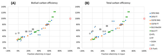
Figure 5.
Carbon conversion efficiency to biofuel products (A) and to total products including tradable co-products (B).
Electrification improved carbon performance of the gasification tracks from about 28–39% for reference cases to 79–123% for the corresponding intensively electrified options. The highly electrified configurations for BLG-FT (BLG-FT_10 and BLG-FT_11 in Table 2) resulted in carbon efficiencies as high as 123% with electricity fraction contributing to as much as two-third of the total energy input, in which case maximum carbon utilization was realized with the help of electrolysis-based H2 and an eSMR tuned to favor reverse water gas shifting. Carbon efficiency higher than 100% is rather the effect of process integration with the pulp mill, i.e., the amount of carbon in BL that ends up in biofuel is more than the amount of carbon in the additional biomass imported to compensate any steam deficit in the pulp mill due to BL gasification. The energy content of additional biomass does not need to match energy in BL gasified since part of the HP steam reduction in the recovery boiler is compensated by energy recovered from the high temperature processes of the biofuel facility, see Figure 3. The concept of using electrolysis hydrogen to boost gasification-based biofuel production has already met industrial interest. The concept is implemented in the “Varennes Carbon Recycling Plant” methanol production facility that Enerkem and Shell are building in Montreal, Canada. Similar designs are also planned for several projects that are in the design phase, such as the SkyFuelH2 Fischer–Tropsch-based SAF plant developed by Uniper and Sasol in Långsele, Sweden as well as the Ecoplanta methanol facility developed by Enerkem and Repsol in Tarragona Spain.
Liquefaction (HTL, FP) and ethanol fermentation (EtOH, ATJ) tracks produce considerable amounts of solid phase, which is considered a valuable co-product in the cases of HTL (char), EtOH and ATJ (pellets), Figure 5B. The benefit of electrification for liquefaction tracks is limited to heating (HTL, EtOH, ATJ), H2 for upgrading (HTL, FP) and H2 for biogas synthesis (EtOH, ATJ). The carbon performance of liquefaction tracks improved to maximum values of 45% EtOH/ATJ, 64% HTL and 57% FP from reference case values 27% EtOH, 24% ATJ, 51% HTL and 49% FP. Utilizing CO2 generated during fermentation for biogas production nearly doubles the carbon conversion efficiency to biofuel for EtOH and ATJ tracks, Figure 5A.
It should be noted that the results shown in Figure 5 assume no carbon credit for any excess heat produced by biofuel tracks, e.g., it can be utilized for district heating (DH), which in turn would reduce biomass usage in CHP systems. From a systems perspective, the saving in biomass use in CHPs could be credited to the bio-electrofuel facility and deducted from its net feedstock intake, if the location of the biorefinery includes a nearby district heating network using biomass CHP. DFB and O2FB tracks generate significant amount of excess heat when credited can raise the carbon performance of the intensively electrified options of these tracks to over 100%, reaching a maximum 295% for O2FB-FT_3. Thus, design and localization of such facilities should enhance utilization of heat recovery for DH or other purposes.
Energy performance on an HHV basis to biofuels and total products is shown in Figure 6, evaluated according to Equations (3) (Figure 6A) and (4) (Figure 6B). Accordingly, electrification does not have discernible systematic impact on energy efficiency, as the increment in biofuel productivity was countered by an increment in electricity input which kept the overall energy efficiency approximately constant for most tracks. The total energy efficiency of DFB, O2FB and liquefaction tracks is higher since DH and valuable co-products are important for these cases, Figure 6B.
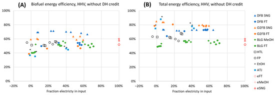
Figure 6.
Energy efficiency excluding carbon credit for excess heat, HHV basis, biofuels (A) and total products (B).
Figure 7 shows the results for the marginal efficiency of electricity addition to biofuels (Figure 7A) and total products (Figure 7B), evaluated according to Equation (5). For gasification tracks, the marginal efficiency decreases with increasing electrification, from >70% (for 5–35% electricity fraction in input) to about 50% for the deeply electrified scenarios (>50% electricity fraction in input), converging to an efficiency representative of pure E-fuels (100% electricity input). It is more electricity-efficient to only eliminate WGS with electrolysis rather than to maximize carbon utilization with a rWGS. It is also evident that eSMR is found to be highly energy-efficient, with marginal efficiency for the BLG-FT track configuration being indicated at 75–80%. In the liquefaction tracks, the addition of electrolysis-derived H2 to the HTL process is highlighted as the most electricity-efficient option, while marginal efficiencies are generally somewhat lower for pyrolysis and ethanol-based tracks. When reviewing the marginal efficiency from electricity to total energy outputs, it is noteworthy that two cases related to ethanol production exhibit marginal efficiencies >250% in Figure 7B. This is explained by the utilization of a MVR heat pump to render lignin pellets available as a by-product, rather than using them internally.
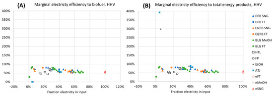
Figure 7.
Marginal electricity efficiency to biofuels (A) and total products (B). Note that reference cases are not plotted since these constitute the baseline for measuring marginal efficiency.
Figure 8 shows the exergy efficiency to biofuels and total products. Exergy efficiency decreases with an increasing fraction of electricity input since electricity has an exergetic value of 100%. The importance of this indicator is questionable in the emerging energy landscape with the growth in intermittent energy supply and decreasing importance of combustion-based electricity production.
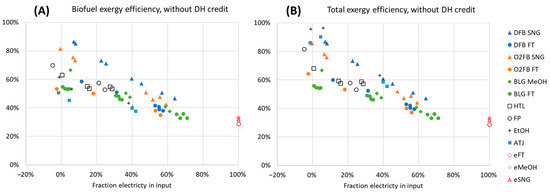
Figure 8.
Exergy efficiency excluding credit for excess heat, biofuels (A) and total products (B).
3.2. Economic Performance
Figure 9 shows CAPEX in MEUR and specific investment in kEUR/kW-biofuel of the technology tracks studied. The E-fuels category combines data for eFT, eSNG and eMeOH, listed here in descending CAPEX order. E-fuels are only shown for comparison to the relevant technology track. For the other categories, every box and whisker represents CAPEX (Figure 9A) and specific investment (Figure 9B) data sets combining the different configurations of a given technology track. According to Figure 9A, CAPEX increases with increasing electrification, i.e., the minima and maxima correspond to the reference and the most electrified configuration involving SOEC technology, respectively. But this is mostly a consequence of the increased production capacity associated with the improved carbon efficiency from electrification. Furthermore, realistic capacities were chosen independently for each track depending on current technology maturity and readiness level for commercialization at the time horizon up to and beyond 2030, leading to different production scales. Thus, CAPEX values should not be directly compared against one another. Specific investment is a more relevant indicator for capital intensity since it weighs production capacity. Comparing Figure 9A,B, it becomes clear most of the categories have a narrower span for specific investment than CAPEX, which indicates that capital added for electrification is justified by increased productivity. In addition, the capital intensity order of the configurations within a category does not necessarily follow that of CAPEX, e.g., BLG-FT_ref has the highest specific investment, 4000 kEUR/kW-FT whereas the most electrified option involving PEM electrolyser BLG-FT_11 has the least, 3100 kEUR/kW-FT.
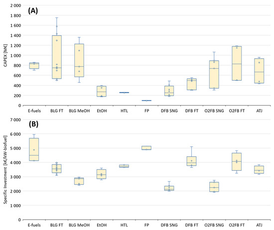
Figure 9.
CAPEX MEUR (A) and specific investment kEUR/kW-biofuel (B).
Figure 10 shows the production cost (PC) of biofuels for all technology tracks evaluated under electricity market prices 30 EUR/MWh (A&B) and 40 EUR/MWh (C&D) plotted versus electricity fraction in input (A&C) and carbon conversion to biofuels (B&D). The PC of all bio-electrofuel tracks fall in the range of 60–140 EUR/MWh and that of E-fuels 105–165 EUR/MWh. The upper and lower PC limits of the bio-electrofuel tracks derive from the reference configurations (without integrated electrification) and are insensitive to changes in electricity price, Figure 10A,C. The HTL, FP and FT tracks, producing a drop in hydrocarbon fuels, correspond to the PC range 100–140 EUR/MWh, whereas the tracks producing other fuel products (MeOH, SNG, EtOH and ATJ tracks) show a PC range of 60–100 EUR/MWh. It is clear that there is a cost penalty for production of drop-in hydrocarbon biofuels compared to alternative fuels and that the PC costs estimated are in agreement with, for example, IEA Bioenergy [41].
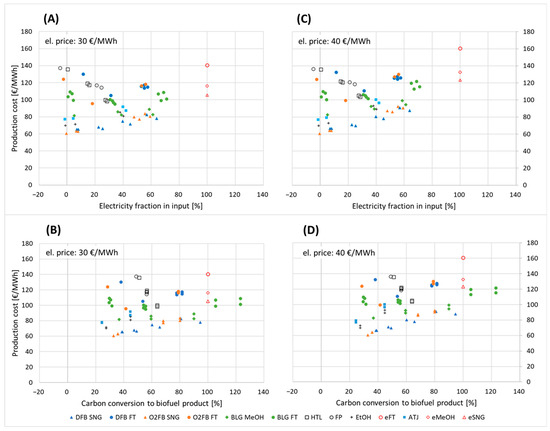
Figure 10.
Production cost under electricity prices 30 EUR/MWh (A,B) and 40 EUR/MWh (C,D) plotted against electricity fraction in input (A,C) and carbon conversion to biofuel (B,D).
The PC ranges for the E-fuels were 105–125 EUR/MWh for eSNG, 115–135 EUR/MWh for eMeOH and 140–165 EUR/MWh for eFT, upper and lower values correspond to electricity prices 30 and 40 EUR/MWh, respectively.
From Figure 10, increased electrification has a different effect on PC for different tracks. On a general level, the PC of the tracks with the highest reference configuration PC (HTL, FP, gasification-FT) is decreased with increased electrification, while the opposite is true for the tracks with the lowest reference configuration PC (gasification-SNG, EtOH, gasification-MeOH). Thus, cost difference between the tracks is smaller in their electrified configurations. Comparing the gasification-based tracks to E-fuels, the PC of the heavily electrified bio-electrofuel configurations, reaching very high carbon efficiency, is about 20–40 EUR/MWh lower than that of the corresponding E-fuels track.
Figure 10B,D illustrate that the gain in carbon conversion efficiencies to biofuels is very high relative to the corresponding marginal change in PC, which could even be lower than the reference PC, notably for tracks involving biogas under reference configurations, i.e., HTL and FP. This is mainly due to much higher biogas prices compared to electricity.
A significant part of the PC derives from the CAPEX, a third to one-half for gasification tracks and about one-half for the liquefaction tracks. The other contributors to PC are feedstock, O&M and electricity. The share of biomass feedstock diminishes with intensifying electrification which becomes dominated by the share of electricity, i.e., the PC of reference configurations is dominated by CAPEX and feedstock and those of intensely electrified counterparts is dominated by CAPEX and electricity.
3.3. Greenhouse Gas Performance
Figure 11 displays the GHG performance of all technology tracks, including E-fuels, when compared to their respective fossil counterparts as indicated in Table 4. The GHG footprint of the reference configurations was characterized by low emissions since they eschewed fossil inputs, and the emissions were primarily driven by the feedstock supply chain. This resulted in favorable GHG footprints due to the low emissions associated with the residue-based feedstocks.
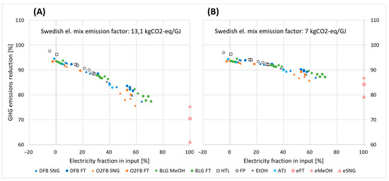
Figure 11.
GHG performance under electricity emission factors kgCO2eq/GJ 13.1 (A) and 7 (B).
As the proportion of electricity in the input increases, the GHG performance becomes increasingly sensitive to electricity emission factors, as depicted in Figure 11. For the official Swedish electricity emission factor of 13.1 kgCO2eq/GJ, the bio-electrofuel tracks can achieve GHG emission reduction potentials ranging from 76% to 98%, while the E-fuels attain reductions ranging from 61% to 75%, as shown in Figure 11A. The lower end of these ranges corresponds to SNG tracks, as SNG requires more hydrogen for a given amount of carbon atoms, necessitating greater electricity use. When the electricity emission factor is reduced to a more realistic estimate for the nearly carbon-neutral Swedish electricity mix, i.e., 7 kgCO2eq/GJ, there is a substantial impact on the GHG emissions reduction potential of the electrified cases. In this scenario, the reduction potential increases to 86–99% for bio-electrofuel tracks and 79–87% for E-fuels, as depicted in Figure 11B.
To further explore the influence of the electricity source, a zero-emission scenario was assessed, and the results are presented in Figure 12. In this scenario, all tracks achieve GHG performance levels exceeding 93%, with the heavily electrified options predominantly surpassing the 97% mark and the E-fuels converging at 100%. The remaining GHG emissions stem from the feedstock supply chain.
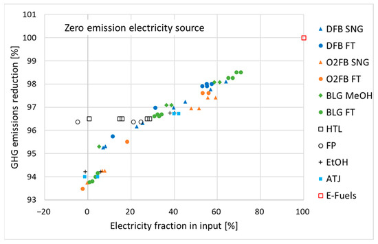
Figure 12.
GHG performance under zero-emission electricity source.
4. Conclusions
The investigation into electricity-enhanced biorefinery concepts, leading to the production of bio-electrofuels, has revealed several important conclusions:
- Improved biorefinery performance: These concepts utilize electrical energy to enhance the performance of biorefineries, resulting in increased biofuel yield and carbon efficiency.
- Efficient use of forest feedstock: by maximizing the utilization of limited forest feedstock, these concepts contribute to the efficient transition of sectors like transportation and chemicals toward sustainable practices.
- Resource efficiency: bio-electrofuel tracks offer resource-efficient options, ensuring maximum utilization of biogenic carbon.
- Key electrification technologies: electrification technologies such as electrolysis, high-temperature direct electric heating and MVR heat pumps are identified as crucial for achieving performance improvements.
- High carbon conversion in gasification tracks: gasification tracks, especially when electrified with technologies like electrolysis-based H2 addition, rWGS and eSMR, achieve carbon conversion efficiencies nearing 100%. Crediting excess heat to replace biomass use further increases efficiency.
- Increased transportation fuel production: many gasification tracks can double or even triple the production of transportation fuels from the same amount of feedstock.
- Improved carbon efficiency in liquefaction tracks: electrified configurations in liquefaction tracks result in significantly improved carbon efficiency, particularly for EtOH/ATJ, HTL and FP.
- Marginal energy performance gains: overall energy performance shows marginal improvements with increased electrification in most tracks, with minor percentage point gains.
- Economic viability: the production cost (PC) of gasification-based bio-electrofuels is in a competitive range, making it an economically viable option. Indirect electrification can enhance overall economic performance, especially when there is high fuel demand.
- High GHG reduction performance: The investigated plant designs generally achieve high greenhouse gas (GHG) reduction performance across all options. Electricity consumption is a significant driver of GHG emissions, but most tracks achieve substantial GHG emissions savings, with the most electrified options surpassing 97%.
- Carbon footprint sensitivity: The performance of bio-electrofuel configurations may outperform pure biofuel tracks, especially when considering the carbon footprint of the electricity source and the feedstock supply chain.
In summary, the investigation suggests that electricity-enhanced biorefinery concepts, particularly in gasification and liquefaction tracks, offer promising avenues for improving biofuel production efficiency, reducing GHG emissions and meeting the growing demand for sustainable transportation fuels. These findings highlight the importance of electrification technologies in the transition toward more sustainable energy and fuel production systems.
Supplementary Materials
The following supporting information can be downloaded at: https://www.mdpi.com/article/10.3390/en16217436/s1. References [42,43,44,45,46,47,48,49,50,51] are cited in the Supplementary Materials.
Author Contributions
S.M. Conceptualization, Methodology, Formal Analysis, Visualization, Writing—Original draft preparation, G.G. Methodology, Formal Analysis, A.L. Conceptualization, Methodology, Writing—Reviewing and Editing, M.S. Formal Analysis, E.F. Conceptualization, Methodology, Visualization, Writing—Reviewing and Editing, Supervision. All authors have read and agreed to the published version of the manuscript.
Funding
This research was carried out within the collaborative research program Renewable transportation fuels and systems (Förnybara drivmedel och system), Project No. 50452-1. The project has been financed by the Swedish Energy Agency and f3—Swedish Knowledge Centre for Renewable Transportation Fuels. We acknowledge for in kind contribution and expertise from St1, Södra and Vattenfall AB.
Data Availability Statement
Not applicable.
Conflicts of Interest
The authors declare no conflict of interest.
References
- International Energy Agency. Net Zero by 2050: A Roadmap for the Global Energy Sector; International Energy Agency: Paris, France, 2021. [Google Scholar]
- Hansson, J.; Hagberg, M.; Hennlock, M.; Karlsson, K.B.; Salvucci, R.; Andersson, M.; Sarasini, S.; Piriya Uteng, T.; Wråke, M. Sustainable Horizons in Future Transport—With a Nordic Focus Project Summary 2015–2019; Nordic Energy Research: Oslo, Norway, 2019. [Google Scholar]
- Alamia, A.; Larsson, A.; Breitholtz, C.; Thunman, H. Performance of Large-Scale Biomass Gasifiers in a Biorefinery, a State-of-the-Art Reference. Int. J. Energy Res. 2017, 41, 2001–2019. [Google Scholar] [CrossRef]
- Jafri, Y.; Furusjö, E.; Kirtania, K.; Gebart, R. Performance of a Pilot-Scale Entrained-Flow Black Liquor Gasifier. Energy Fuels 2016, 30, 3175–3185. [Google Scholar] [CrossRef]
- Pettersson, K.; Harvey, S. CO2 Emission Balances for Different Black Liquor Gasification Biorefinery Concepts for Production of Electricity or Second-Generation Liquid Biofuels. Energy 2010, 35, 1101–1106. [Google Scholar] [CrossRef]
- Motta, I.L.; Miranda, N.T.; Maciel Filho, R.; Wolf Maciel, M.R. Biomass Gasification in Fluidized Beds: A Review of Biomass Moisture Content and Operating Pressure Effects. Renew. Sustain. Energy Rev. 2018, 94, 998–1023. [Google Scholar] [CrossRef]
- Frankó, B.; Galbe, M.; Wallberg, O. Bioethanol Production from Forestry Residues: A Comparative Techno-Economic Analysis. Appl. Energy 2016, 184, 727–736. [Google Scholar] [CrossRef]
- Frankó, B.; Galbe, M.; Wallberg, O. Influence of Bark on Fuel Ethanol Production from Steam-Pretreated Spruce. Biotechnol. Biofuels 2015, 8, 15. [Google Scholar] [CrossRef]
- Sassner, P.; Galbe, M.; Zacchi, G. Techno-Economic Evaluation of Bioethanol Production from Three Different Lignocellulosic Materials. Biomass Bioenergy 2008, 32, 422–430. [Google Scholar] [CrossRef]
- Jafri, Y.; Ahlström, J.M.; Furusjö, E.; Harvey, S.; Pettersson, K.; Svensson, E.; Wetterlund, E. Double Yields and Negative Emissions? Resource, Climate and Cost Efficiencies in Biofuels with Carbon Capture, Storage and Utilization. Front. Energy Res. 2021, 10, 797529. [Google Scholar] [CrossRef]
- Tews, I.J.; Zhu, Y.; Drennan, C.; Elliott, D.C.; Snowden-Swan, L.J.; Onarheim, K.; Solantausta, Y.; Beckman, D. Biomass Direct Liquefaction Options. TechnoEconomic and Life Cycle Assessment; Pacific Northwest National Lab.: Richland, WA, USA, 2014. [Google Scholar] [CrossRef]
- Funkenbusch, L.T.; Mullins, M.E.; Vamling, L.; Belkhieri, T. Technoeconomic Assessment of Hydrothermal Liquefaction Oil from Lignin with Catalytic Upgrading for Renewable Fuel and Chemical Production. WIREs Energy Environ. 2019, 8, e319. [Google Scholar] [CrossRef]
- Carrasco, J.L.; Gunukula, S.; Boateng, A.A.; Mullen, C.A.; Desisto, W.J.; Wheeler, M.C. Pyrolysis of Forest Residues: An Approach to Techno-Economics for Bio-Fuel Production q. Fuel 2017, 193, 477–484. [Google Scholar] [CrossRef]
- Hannula, I. Hydrogen Enhancement Potential of Synthetic Biofuels Manufacture in the European Context: A Techno-Economic Assessment. Energy 2016, 104, 199–212. [Google Scholar] [CrossRef]
- Karl, J.; Pröll, T. Steam Gasification of Biomass in Dual Fluidized Bed Gasifiers: A Review. Renew. Sustain. Energy Rev. 2018, 98, 64–78. [Google Scholar] [CrossRef]
- Puricelli, S.; Cardellini, G.; Casadei, S.; Faedo, D.; van den Oever, A.E.M.; Grosso, M. A Review on Biofuels for Light-Duty Vehicles in Europe. Renew. Sustain. Energy Rev. 2021, 137, 110398. [Google Scholar] [CrossRef]
- Pio, D.T.; Tarelho, L.A.C.; Pinto, P.C.R. Gasification-Based Biorefinery Integration in the Pulp and Paper Industry: A Critical Review. Renew. Sustain. Energy Rev. 2020, 133, 110210. [Google Scholar] [CrossRef]
- Dossow, M.; Dieterich, V.; Hanel, A.; Spliethoff, H.; Fendt, S. Improving Carbon Efficiency for an Advanced Biomass-to-Liquid Process Using Hydrogen and Oxygen from Electrolysis. Renew. Sustain. Energy Rev. 2021, 152, 111670. [Google Scholar] [CrossRef]
- Mesfun, S.; Engvall, K.; Toffolo, A. Electrolysis Assisted Biomass Gasification for Liquid Fuels Production. Front. Energy Res. 2022, 10, 799553. [Google Scholar] [CrossRef]
- Onarheim, K.; Hannula, I.; Solantausta, Y. Hydrogen Enhanced Biofuels for Transport via Fast Pyrolysis of Biomass: A Conceptual Assessment. Energy 2020, 199, 117337. [Google Scholar] [CrossRef]
- Hillestad, M.; Ostadi, M.; Alamo Serrano, G.D.; Rytter, E.; Austbø, B.; Pharoah, J.G.; Burheim, O.S. Improving Carbon Efficiency and Profitability of the Biomass to Liquid Process with Hydrogen from Renewable Power. Fuel 2018, 234, 1431–1451. [Google Scholar] [CrossRef]
- Albrecht, F.G.; Nguyen, T. Van Prospects of Electrofuels to Defossilize Transportation in Denmark—A Techno-Economic and Ecological Analysis. Energy 2020, 192, 116511. [Google Scholar] [CrossRef]
- Brynolf, S.; Taljegard, M.; Grahn, M.; Hansson, J. Electrofuels for the Transport Sector: A Review of Production Costs. Renew. Sustain. Energy Rev. 2018, 81, 1887–1905. [Google Scholar] [CrossRef]
- Poluzzi, A.; Guandalini, G.; Guffanti, S.; Martinelli, M.; Moioli, S.; Huttenhuis, P.; Rexwinkel, G.; Palonen, J.; Martelli, E.; Groppi, G.; et al. Flexible Power and Biomass-To-Methanol Plants With Different Gasification Technologies. Front. Energy Res. 2022, 9, 795673. [Google Scholar] [CrossRef]
- Habermeyer, F.; Kurkela, E.; Maier, S.; Dietrich, R.U. Techno-Economic Analysis of a Flexible Process Concept for the Production of Transport Fuels and Heat from Biomass and Renewable Electricity. Front. Energy Res. 2021, 9, 723774. [Google Scholar] [CrossRef]
- Wismann, S.T.; Engbæk, J.S.; Vendelbo, S.B.; Bendixen, F.B.; Eriksen, W.L.; Aasberg-Petersen, K.; Frandsen, C.; Chorkendorff, I.; Mortensen, P.M. Electrified Methane Reforming: A Compact Approach to Greener Industrial Hydrogen Production. Science 2019, 364, 756–759. [Google Scholar] [CrossRef] [PubMed]
- Fornell, R. Process Integration Studies on Kraft Pulp-Mill-Based Biorefineries Producing Ethanol. Ph.D. Thesis, Chalmers University of Technology, Heat and Power Technology, Department of Energy and Environment, Gothenburg, Sweden, 2012. [Google Scholar]
- Geleynse, S.; Brandt, K.; Garcia-Perez, M.; Wolcott, M.; Zhang, X. The Alcohol-to-Jet Conversion Pathway for Drop-In Biofuels: Techno-Economic Evaluation. ChemSusChem 2018, 11, 3728–3741. [Google Scholar] [CrossRef]
- van Dyk, S.; Saddler, J. Progress in the Commercialization of Biojet/Sustainable Aviation Fuels (SAF): Technologies, Potential and Challenges; IEA Bioenergy: Paris, France, 2021; ISBN 9781910154878. [Google Scholar]
- Naqvi, M.; Yan, J.; Dahlquist, E. Black Liquor Gasification Integrated in Pulp and Paper Mills: A Critical Review. Bioresour. Technol. 2010, 101, 8001–8015. [Google Scholar] [CrossRef]
- Carvalho, L.; Lundgren, J.; Wetterlund, E.; Wolf, J.; Furusjö, E. Methanol Production via Black Liquor Co-Gasification with Expanded Raw Material Base—Techno-Economic Assessment. Appl. Energy 2018, 225, 570–584. [Google Scholar] [CrossRef]
- Berglin, N.; Lovell, A.; Delin, L.; Törmälä, J. The 2010 Reference Mill for Kraft Market Pulp. In Proceedings of the Tappi PEERS Conference, Portland, OR, USA, 2–5 October 2011; pp. 191–197. [Google Scholar]
- Stora Källor för Biogen CO2 Lista. Available online: https://bioenergitidningen.se/app/uploads/sites/2/2019/04/Stora-kallor-för-biogen-CO2-lista.pdf (accessed on 21 February 2022).
- Brandberg, A.; Hjortsberg, H.; Sävbark, B.; Ekbom, T.; Hjerpe, C.J.; Landälv, I. BioMeeT. Planning of Biomass-Based Methanol Energy Combine—Trollhättan Region; Nykomb Synergetics AB: Stockholm, Sweden, 2000. [Google Scholar]
- Schmidt, O.; Gambhir, A.; Staffell, I.; Hawkes, A.; Nelson, J.; Few, S. Future Cost and Performance of Water Electrolysis: An Expert Elicitation Study. Int. J. Hydrogen Energy 2017, 42, 30470–30492. [Google Scholar] [CrossRef]
- Energymyndigheten Wood Fuel and Peat Prices. Available online: https://pxexternal.energimyndigheten.se/pxweb/sv/Trädbränsle-ochtorvpriser/?rxid=79e3c147-398b-4bb3-9b08-517ec64c39d1 (accessed on 23 August 2022).
- Svenska Kraftnät. Långsiktig Marknadsanalys; Svenska Kraftnät: Stockholm, Sweden, 2021. [Google Scholar]
- Thunman, H.; Gustavsson, C.; Larsson, A.; Gunnarsson, I.; Tengberg, F. Economic Assessment of Advanced Biofuel Production via Gasification Using Cost Data from the GoBiGas Plant. Energy Sci. Eng. 2019, 7, 217–229. [Google Scholar] [CrossRef]
- de la Fuente, T.; González-García, S.; Athanassiadis, D.; Nordfjell, T. Fuel Consumption and GHG Emissions of Forest Biomass Supply Chains in Northern Sweden: A Comparison Analysis between Integrated and Conventional Supply Chains. Scand. J. For. Res. 2017, 32, 568–581. [Google Scholar] [CrossRef]
- Jafri, Y.; Wetterlund, E.; Mesfun, S.; Rådberg, H.; Mossberg, J.; Hulteberg, C.; Furusjö, E. Combining Expansion in Pulp Capacity with Production of Sustainable Biofuels—Techno-Economic and Greenhouse Gas Emissions Assessment of Drop-in Fuels from Black Liquor Part-Streams. Appl. Energy 2020, 279, 115879. [Google Scholar] [CrossRef]
- Brown, A.; Waldheim, L.; Landälv, I.; Saddler, J.; Ebadian, M.; McMillan James, D.; Bonomi, A.; Klein, B. Advanced Biofuels—Potential for Cost Reduction, IEA Bioenergy: Task 41: 2020:01; IEA Bioenergy: Paris, France, 2020. [Google Scholar]
- Fuel Cell Technology—Elcogen. Available online: https://elcogen.com/ (accessed on 22 August 2022).
- HIAT-Hydrogen and Informatics Institute of Applied Technolgies. Available online: https://www.hiat.de/ (accessed on 22 August 2022).
- Klop, E. Steaming Ahead with MVR. Available online: https://blueterra.nl/wp-content/uploads/2018/03/Steaming-ahead-with-MVR-COSPP.pdf (accessed on 22 August 2022).
- Liang, Z.; Rongwong, W.; Liu, H.; Fu, K.; Gao, H.; Cao, F.; Zhang, R.; Sema, T.; Henni, A.; Sumon, K.; et al. Recent Progress and New Developments in Post-Combustion Carbon-Capture Technology with Amine Based Solvents. Int. J. Greenh. Gas Control. 2015, 40, 26–54. [Google Scholar] [CrossRef]
- Xie, N.; Chen, B.; Tan, C.; Liu, Z. Energy Consumption and Exergy Analysis of MEA-Based and Hydrate-Based CO2 Separation. Ind. Eng. Chem. Res. 2017, 56, 15094–15101. [Google Scholar] [CrossRef]
- Baltrusaitis, J.; Luyben, W.L. Methane Conversion to Syngas for Gas-to-Liquids (GTL): Is Sustainable CO2 Reuse via Dry Methane Reforming (DMR) Cost Competitive with SMR and ATR Processes? ACS Sustain. Chem. Eng. 2015, 3, 2100–2111. [Google Scholar] [CrossRef]
- Arvidsson, M.; Morandin, M.; Harvey, S. Biomass Gasi Fi Cation-Based Syngas Production for a Conventional Oxo Synthesis Plant—Process Modeling, Integration Opportunities, and Thermodynamic Performance. Energy Fuels 2014, 28, 4075–4087. [Google Scholar] [CrossRef]
- Glenk, G.; Reichelstein, S. Economics of Converting Renewable Power to Hydrogen. Nat. Energy 2019, 4, 216–222. [Google Scholar] [CrossRef]
- Marsidi, M. Industrial Mechanical Vapour Recompression (MVR). Available online: https://energy.nl/wp-content/uploads/industrial-mechanical-vapour-recompression-1-7.pdf (accessed on 30 October 2023).
- Liu, G.; Larson, E.D.; Williams, R.H.; Kreutz, T.G.; Guo, X. Making Fischer-Tropsch Fuels and Electricity from Coal and Biomass: Performance and Cost Analysis. Energy Fuels 2011, 25, 415–437. [Google Scholar] [CrossRef]
Disclaimer/Publisher’s Note: The statements, opinions and data contained in all publications are solely those of the individual author(s) and contributor(s) and not of MDPI and/or the editor(s). MDPI and/or the editor(s) disclaim responsibility for any injury to people or property resulting from any ideas, methods, instructions or products referred to in the content. |
© 2023 by the authors. Licensee MDPI, Basel, Switzerland. This article is an open access article distributed under the terms and conditions of the Creative Commons Attribution (CC BY) license (https://creativecommons.org/licenses/by/4.0/).