Abstract
In this paper, a non-linear programming method allowing for the optimization of the structure of high-current circuits that supply resistance-arc furnaces was presented. In the case of resistance-arc furnaces, two types of asymmetries most often occur: structural and operational ones. The structural asymmetry is related to the construction of a bifilar high-current busduct, which leads to the so-called short network. Knowing the parameters of the high-current busduct allows one to determine the operating characteristics of the arc furnace. It is also necessary to know the energy consumed in individual steps of the arc furnace operation. The method proposed in this paper makes it possible to establish guidelines for the modernization of a short network in order to eliminate asymmetry. The presented method was verified on a real object by conducting experimental tests on a furnace with a power of 12 MVA. Experimental tests were first carried out for a furnace with asymmetry, and then, by conducting simulation tests, guidelines for changing the design of the short network were determined. The measurements carried out after the modernization of the short network confirmed that the furnace was in a symmetrical operating condition and confirmed the correctness of the calculation method proposed in this paper.
1. Introduction
In the metallurgical industry, the submerged arc furnace (SAF), also known as the electric resistance furnace (ERF), is mainly used to reduce the use of raw materials such as smelting ores, carbonaceous reducing agents and solvents. It produces ferrosilicon, ferromanganese, ferrochrome, ferrotungsten, silicomanganese alloy and other ferroalloys. The SAF is an electric furnace with huge power consumption, even over 40 MVA, and the maximum current can reach tens of thousands of amperes [1,2,3,4,5,6,7].
The short network of the SAF is the high current line from the secondary side of the furnace transformer to the electrodes. Its design should ensure the lowest possible power losses as well as the possibly even distribution of phase power (low power asymmetry) delivered to the furnace. The so-called dead-phase and live-phase phenomena appear in practice [6,8]. Therefore, the high-current busduct should be of low resistance and reactance, and the resistances and inductances of its individual phases should be the same. In order to ensure the smallest possible asymmetry of the phase powers in the zones near the electrodes, the electrodes are placed symmetrically along the circumference of the circle, forming an equilateral triangle. Thus, the distances of individual electrodes from the furnace transformer are not the same, which results in different lengths of the high-current busducts in individual phases. This in turn results in different phase impedances—the short network of the SAF is asymmetric.
In order to reduce the equivalent-phase reactances of the short electric network of the SAF, bifilar high-current busbars in delta connection to the electrodes are used (the so-called “knapsack” connection) [6,8,9,10,11], as seen in Figure 1. This connection allows one to increase the power factor of the SAF power supply system. In addition, the currents in high-current circuits with such a power supply are √3 times lower than in the systems which use star connection of the electrodes. As seen in the result, apart from the reduction in demand for reactive power consumption, active power losses in the short-circuit conductors are also lowered.
Figure 1.
Layout of the short electric network of the SAF in delta connection to the electrodes: 1—rigid high-current busduct (copper water-cooled pipes), 2—flexible high-current busduct (copper strips), 3—water-cooled copper or aluminum pipes (placed on the electrodes supporting arms ending with copper plates and clamps), 4—electrode (red—pipes with forward currents, blue—pipes with return currents).
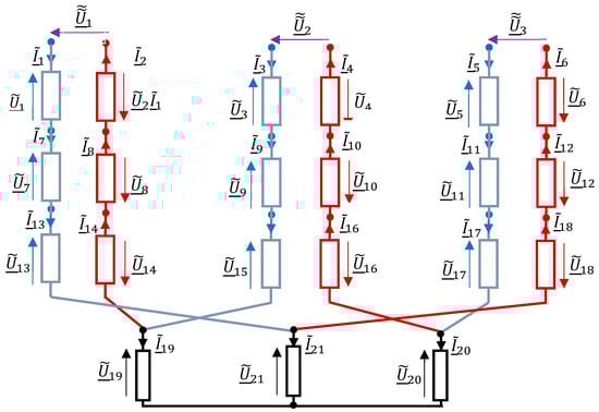
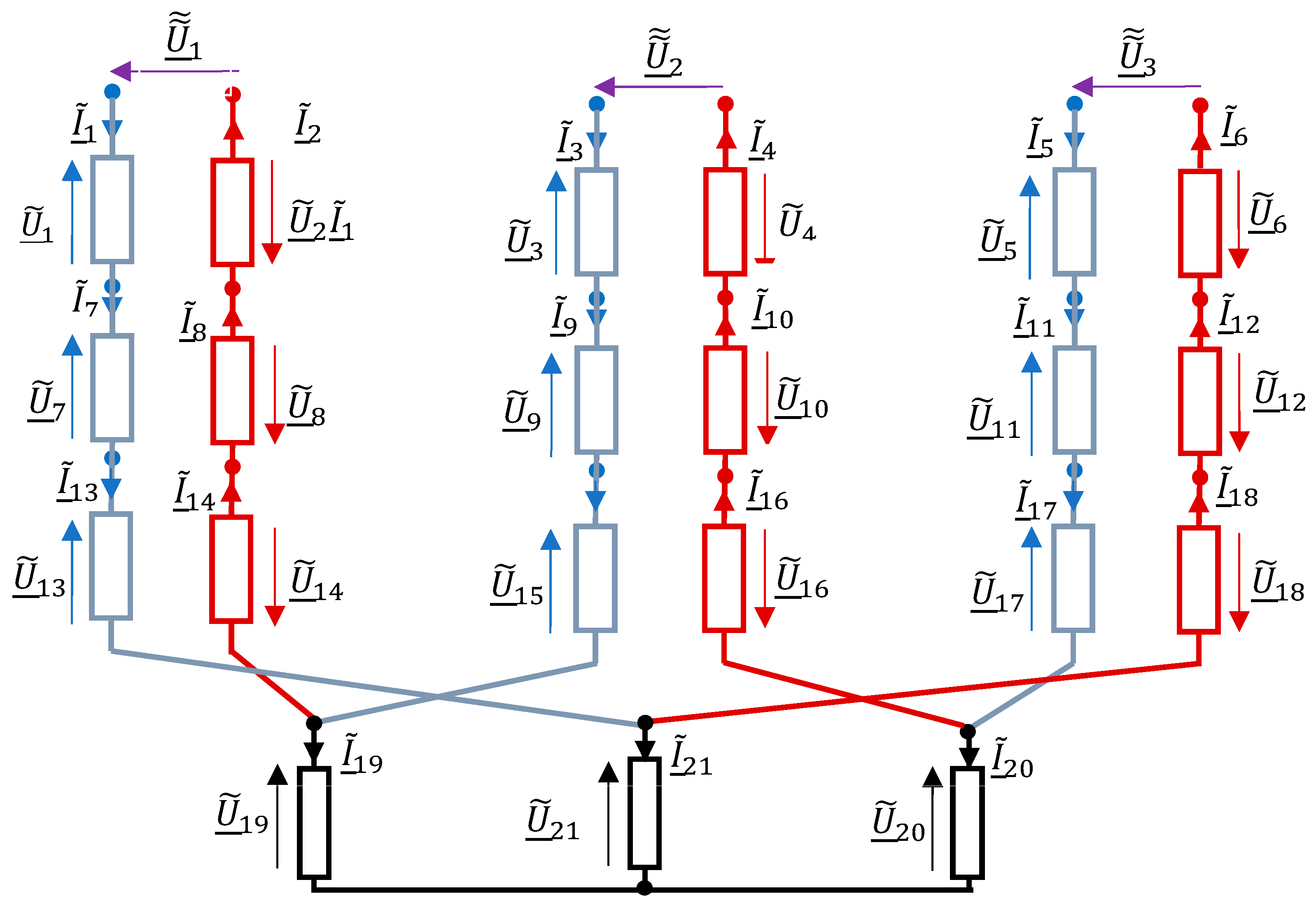
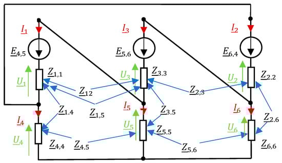
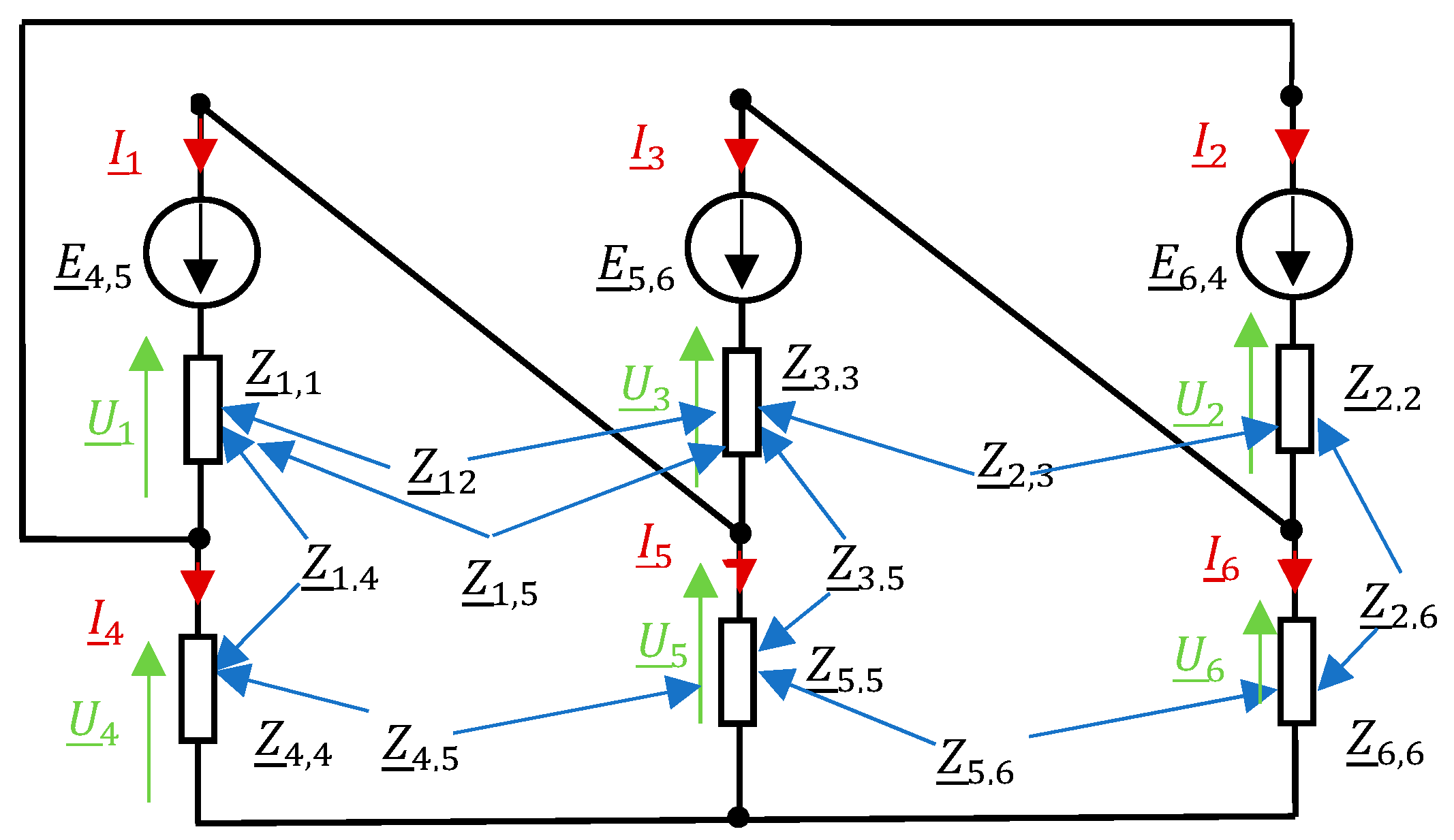
The bath of the SAF forms a star circuit, with the metal pool as the star point. Busbars are connected in delta to the electrodes, which together with the furnace bath form a star circuit and an equivalent circuit is represented in combined delt-star connection, as seen in Figure 2.
Figure 2.
Equivalent circuit of the high-current short network of a SAF specifying the numbering of individual conductors used in Section 2 (red—forward line, blue—return line).
However, if the SAF is powered from one three-phase transformer, then the bifilar loops of the high-current busduct have different lengths (Figure 1), which in general leads to asymmetry in the voltages between the electrodes as well as the phase voltages across the electrodes with respect to the neutral state of the furnace bath. Hence, the power factor of the SAF can hardly exceed 0.85. The term “low power” is synonymous to a circuit with high reactance in reference to resistance [8]. According to the structural characteristics and working characteristics of the SAF, 70% of the system reactance of the SAF is generated by the short electric network. A lower power factor not only reduces the efficiency of the transformer and consumes a significant amount of wasted power, but it also imposes additional power fines by the power department. At the same time, due to the manual control of the electrodes and the stacking process, the power imbalance between the three phases increases, and the highest unbalance can reach more than 20%, which leads to low smelting efficiency and high electricity costs.
The literature related to arc furnace modeling is very extensive. This topic is still valid and new directions are constantly being set in the modeling of electric arc furnaces [9,10]. The accurate modeling of the electric arc furnace is necessary to study its impact on power systems [11,12,13,14,15]. It is necessary to know the energy consumed within the individual steps of the arc furnace operation [16,17]. Therefore, new theories are constantly being defined that enable a more accurate analysis of energy transfer and improvement in power control [18,19]. Knowledge of the parameters of the high-current circuit makes it possible to determine the operating characteristics of the arc device. In the case of three-phase arc furnaces, two types of asymmetry can be distinguished: structural and operational ones, and both cases are the subject of many scientific works. In the literature on the subject, one can find a number of methods for determining the operational asymmetry of voltages and currents as well as harmonic analysis [20,21]. In addition, much attention is paid to the determination of electrical parameters of real arc furnaces [22,23].
In this paper, it will be shown that, in such a case, there are several configurations of piping systems in a rigid bifilar high-current busduct that result in magnetic couplings, causing the symmetry of the phase voltages across the electrodes with respect to the neutral state of the furnace bath with equal equivalent resistances of the zones near the electrodes. Such a configuration is the transposition of pipes in the rigid part of the short electric network shown in Figure 1 in cross-sections AA’ and BB’. This solution enables the supply of the same active power to the electrode zone, which is one of the conditions for an optimal production process.
2. Analysis of the High-Current Short Network
Bearing in mind the construction of the algorithm for the task defined in Section 1, a mathematical model should be developed at the outset to enable the calculation of current distribution and voltage distribution in the furnace’s short network for a given geometric configuration. An exemplary geometrical configuration of the furnace is shown in Figure 1. The configuration is set in a rectangular coordinate system with the z axis located in the furnace axis and the origin at the bottom of the tank. The bifilar high-current busduct consists of copper pipes of a given diameter, led in straight sections from the transformer terminals to the stationary parts of the garlands. The number of pipes carrying current in the same direction for each phase is Nt, which gives a total of 6Nt pipes. The bifilar loop for the individual phases therefore contains 2Nt interlaced pipes, as shown in Figure 1 (Nt = 4). The geometry of the busduct is set in the form of geometrical coordinates of the starting and ending points and the bending points of the tube axes:
where Mk means the number of start and end points as well as bending points of the tube axes of the k-th pipe.
Copper sheet packages are made of longitudinal strips with a small cross-section and are connected in groups comprising several items. Depending on the assumed value of the flowing current, a specific number of packages is used, exceeding the permissible current density for an air-cooled copper sheet. The ends of the packages are attached in the so-called current boxes, enabling the connection of the liquid cooling the high-current busduct and the connections to the electrodes with contact plates.
The flexible parts of the short network supplying currents from the high-current busduct to the moving electrodes were assumed in the form of two parallel sets of Nblach plates of thickness gb and width db, distant from each other by dp. The length of the flexible part was assumed as lb.
In order to implement the triangle of transformer winding connections on the electrodes, two such sets of flexible part connections are used (Figure 2) distant from each other by hb for each phase. There is a total of six flex sets in the furnace short network. The geometry of the flexible part is given in the form of rectilinear sections approximating the catenary curve of the sag of these plates. Since in the plates there is a very strong skin effect, its division into elements is assumed for analysis, which gives rectilinear elements for analysis, similar to a square section. In total, the flexible part kit contains such elements. The geometry of the flexible part is given in the form of geometrical coordinates of the start and end points as well as the bending points of the axes of rectilinear elements with a rectangular cross-section, i.e.,
where Mk means the number of start and end points, as well as points of bending the axis of the k-th element with a rectangular cross-section of the flexible part.
The supply to the electrodes from the movable flexible part is also carried out using the same pipes as the high-current busduct (Figure 1). Each flexible assembly is connected via pipes to the pressure plate on the electrode for a total of pipes. The geometry of such a system is also given in the form of geometrical coordinates of the start and end points and the bending points of the pipe axes from the movable part of the garlands to the pressure plate, i.e.,
where Mk is the number of starting and ending points as well as bending points of the pipe axes of the k-th pipeline on the lead to the electrodes. Taking into account the three electrodes of the three-electrode furnace, the number of short network wire elements is
During the system analysis, these elements were numbered sequentially. Numbering in the circuit starts successively from the tubular wires of the high-current busduct, through the flexible part and the connection to the electrodes, ending with the electrodes. In the set of N elements of the furnace power supply system, means the number of the element which is the last one in the l-th bundle of wires connected in parallel, leading the current in the same direction of a given phase. The full set of element numbering made in this way is as follows:
Bearing in mind the analysis of current flow and voltage distribution in the furnace’s short network, the relationship between currents and voltage drops on individual elements should be determined in the form of an algebraic system of complex equations (application of Kirchhoff’s law), i.e.,
in which
and
in which
where
- —number of wires connected in parallel in the i-th package (i = 1, 2, …, 21);
- —resistance of the m-th element of the i-th conductor of the short network;
- —self-induction of the m-th element of the i-th conductor of the short network;
- —mutual induction between the m-th element of the i-th cable of the short network and the n-th element of the j-th cable of the short network.
Then, the vectors of currents and voltages of the j,i-th package of elements connected in parallel are as follows:
where
For industrial frequency, the skin effect can be neglected and then the self-inductance of a tubular conductor is given by the well-known formula [24,25,26,27]
in which
and
- —internal radius of the cylindrical conductor;
- —external radius of the cylindrical conductor;
- —length of the cylindrical conductor.
Finally, the impedance of a conductive pipe is given by the formula
For a parallel bundle of cylindrical conductors, the proximity effect can also be neglected. The permissible approximation of the axes of cylindrical conductors in a bifilar system, for construction reasons, is not smaller than the outer diameter of the conductors, which in this case has little effect on the equivalent reactances of individual phases. This is also because the decisive section of this part of the short network affecting the value of the equivalent phase inductance is the distribution of the pipes from the interlacing system to the stationary part of the garlands. In this part of the system, the bifilar compensation of the mutual induction forces disappears, which causes a multiple equivalent increase in the inductance of the individual phases of this section. Such simplification of the model is important in optimization tasks. Thus, in the following considerations, the impedance of the conductive tube may be determined from Formula (19).
To model current distribution in the flexible part of the supply system, linear elements with a rectangular cross-section are used (2). They are created by dividing the metal plate into parts. Such a division is important due to the skin and proximity effects. The self-inductance of such an element with transverse dimensions a, b and length l at constant current density is expressed by the formula [28]
In solving the integral (11), the following formula is obtained for the self-inductance of a rectangular conductor of finite length [29,30,31,32]:
where
and
Since the lengths of the individual elements of the rectilinear sections of the short network are much greater than the transverse dimensions, a simplified formula is used to calculate their mutual induction coefficients, assuming that these sections are filament wires. Then, the formulas given by Grover in [32] can be used. For any spatial configuration of such filaments, the mutual inductances between them are given by the following formula:
where are the rectangular coordinates designating the beginnings and ends of rectilinear elements in 3D space.
For integral (27), there is a solution in analytical form with a very complex structure due to many cases of location of vectors relative to each other in three-dimensional space and .
In modelling, due to the low value of the specific conductivity of the carbon mass of the electrodes, the skin effect is omitted, which allows the self-inductance formula for constant current density to be applied with high accuracy in the following form [24,25,26,27]:
where means radius of electrode and is length of electrode.
Considering the transformation of the system of Equation (9), the inverse matrix of matrix (11) is calculated:
The resultant current of the i-th packet according to Kirchhoff’s first law is
On the parallel connected elements of the j-th packet, the voltage is identical and equals
Taking into account the equality (34), according to the Formula (31), the current of the l-th element of the i-th packet can be written in the following form:
If Formula (35) is applied to Equation (33), then
Let us denote
and
Thus, it is possible to write Equation (36) in matrix form:
Bearing in mind further transformations related to the serial connection of short network parallel packets, we calculate the inverse matrix which allows us to write Equation (39) in the following form:
Individual bundles of wires are connected in series, so according to the second Kirchhoff’s law (Figure 2), another reduction in the matrix can be made, taking into account the series connection of elements. According to the markings in Figure 3, the second Kirchhoff law gives
Figure 3.
Connection graph of a short network after reduction in parallel elements (red—impedances of forward line, blue—impedances of return line).
Taking into account the following markings:
Then, the system of Equation (24) can be written in the form
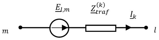
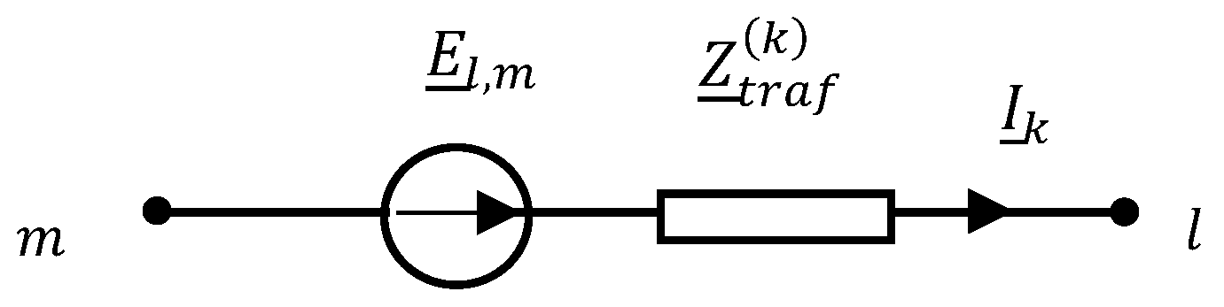
In this way, the impedance matrix is generated, which combines the voltage drops on the high-current circuit elements with the corresponding total currents of these elements. This matrix is the starting point for the analysis of the flow of currents in the elements of the high-current busduct. For this purpose, the voltage excitations realized in the system by transformers are modeled using the ideal electromotive force with internal impedance (Figure 4).
Figure 4.
Electromotive force with internal impedance .
The voltage excitations (Figure 4) can therefore be expressed by
The equivalent resistances of the furnace load can be placed in the constructed model as a series connection of elements (electrodes) adding to the self-impedance .
The modified self and mutual impedance matrix of the furnace short network, supplemented with the internal impedance of the transformer and the furnace load resistances, can be written in the following form:
Knowledge of the matrix (50) defining the relationship between the voltage drops on equivalent impedances of the short network system and their respective currents allows for the analysis of the system, i.e.,
The equivalent diagram of the short network system is shown in Figure 5.
Figure 5.
Equivalent diagram of the short network system.
Based on Kirchhoff’s laws, this can be written as follows:
where
and
Thus, the final form of the equations was obtained, allowing for the calculation of the flow of currents in individual branches of the short network. The knowledge of this flow, in turn, makes it possible, by performing reverse operations, to compute the current flow in individual elements of the short network (e.g., in pipes). Since matrix , which is the basis for the calculations, is a function of the geometric configuration of the short network, it is possible to study the impact of the configuration, and especially its essential elements, on this distribution. In summary, a tool for the synthesis of a short network was obtained, which can be used in the optimization tasks of the iron-alloy production process.
3. Formulation of the Task of Optimizing the Structure of the Short Network
If the arc resistance furnace is powered from a single three-phase transformer, then the bifilar loops of the high-current busduct must have different lengths (Figure 1), which generally causes asymmetry in the voltages between the electrodes as well as the phase voltages on the electrodes relative to the zero of the furnace tank. In this chapter, it will be shown that, in such a case, there exist such configurations of piping systems in a bifilar high-current circuit that give such magnetic couplings leading to symmetry in the phase voltages on the electrodes relative to the zero of the furnace tank with equal equivalent resistances of the zones near the electrodes. Bearing in mind the definition of a set of the busduct configurations for which such a solution is possible, let us note the influence of the way of interlacing the pipes on the equivalent reactance of the bifilar busduct.
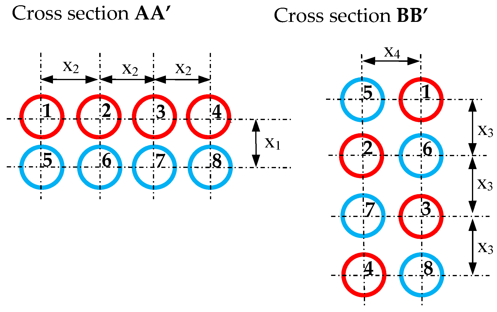
Table 1 presents example calculations of impedance of the bifilar busduct in μΩ for cross-section AA’ as a function of parameters x1 and x2 (Figure 6), assuming that the length of the busduct is 7 m, the diameter of the pipes is 50 mm and the wall thickness is 10 mm. In turn, Table 2 presents examples of bifilar busduct impedance calculations in μΩ for the BB’ cross-section as a function of x3 and x4 parameters (Figure 6), also assuming that the busduct length is 7 m, the diameter of the tubes is 50 mm and the wall thickness is 10 mm.
Table 1.
Impedance of bifilar busduct in μΩ for cross-section AA’ as a function of parameters x1 and x2.
Figure 6.
Cross-sections of bifilar high-current busduct (red—pipes with forward currents, blue—pipes with return currents).
Table 2.
Impedance of bifilar busduct in μΩ for cross-section BB’ as a function of parameters x3 and x4.
The calculations presented in Table 1 and Table 2 show that, for the interlacing of the pipes as in cross-section BB’, the reactance is about two times lower than for the configuration shown in cross-section AA’. This fact can be used to define an acceptable set of geometrical configurations of the pipes, for which there is such a configuration of tubular wires in a bifilar high-current busduct that gives such magnetic couplings that will cause symmetry in the phase voltages on the electrodes relative to the zero of the furnace tank with equal equivalent resistances of the zones near the electrodes. Since the arrangement of electrodes (Figure 1) is symmetrical, the longer outer phases should have a BB’ type cross-section, for which the individual reactances are about twice lower than for the AA’ type cross-section. The middle phase (Figure 1) is much shorter, so in order to equalize the reactance with respect to the outer phases, the AA’ cross-section should be used.
Let the geometrical configuration of the short furnace network be given in the form of geometrical coordinates of the start and end points and the points of bending the axes of the pipes in the form of the following matrix:
in which is the number of starting points, end points and bending points of the pipe axes of the k-th pipeline.
The matrix (61) of rectangular coordinates is basically generated for a given resistance-arc furnace by the designer of the short network for the given active power of the furnace. However, taking into account the selection of the equivalent impedances of the bifilar high-current busduct enabling the symmetrization of the active power of the zones near the electrodes, we will change the matrix (61) using the following parameters:
which determine the mutual location of the tube axes for the AA’ and BB’ cross-sections as shown in Figure 6. In this way, a matrix function of an independent vector variable of parameters was obtained. Let us then assume that the furnace supply voltages are symmetrical and that the equivalent resistances of the zones near the electrodes are the same, which can be written in the following form:
First, for the variable configuration of the short network defined by the matrix function , the matrix is generated in Equation (52) and then, under the conditions of supply (63) and load (64), this system is solved due to the currents of the short network. Then, the solution is
The solution currents (65) can then be considered as functions of the vector variable of parameters . Due to the symmetry (63) and (64), one can search for such a modification of the geometrical configuration of the short network for which the RMS values of the electrode currents (Figure 4) will be the same. This means that the following equality conditions must be fulfilled in the optimization task:
For design reasons and due to active power losses caused by the proximity effect, the distances between the axes of the pipes should be sufficiently large. With this in mind, let us introduce an inequality constraint of the following type to the optimization calculations:
where is taken as the 1.75 outer-diameter pipe , i.e., .
Due to the relatively large distance of the transformer from the axis of the furnace, its short network causes relatively high values of inductive reactance. In order to minimize the apparent power of the transformer, tan(φ) is assumed as a function of the optimization task. On the basis of determined currents of the high-current busduct , the complex power received from the transformer by the furnace can be determined as follows:
The objective function in the optimization problem as tan(φ) can be written as
The task of searching for such a busduct configuration for which it is possible to achieve the symmetry of the phase voltages on the electrodes relative to the furnace tank zero with equal equivalent resistances of the zones near the electrodes was brought to the following non-linear programming task:
The considerations show that the objective function and the function of equality constraints do not have an explicit analytical form but are defined by the results of certain mathematical operations. The algorithm for forming the objective function and equality constraints for the non-linear programming task can be defined as follows (Algorithm 1):
| Algorithm 1: The algorithm for forming the objective function and equality constraints for the non-linear programming task |
|
4. Application of the Sliding Penalty Function in the Optimization Problem
As it can be seen from the considerations in the previous section, the objective functions f(x) and equality constraints h(x) do not have an analytical form, which may cause some difficulties in calculating their partial derivatives. Bearing this in mind, to solve the defined problem of non-linear programming, it is proposed to use the method of the sliding penalty function [33] based on a certain extended Lagrange function, which can be minimized using gradient-free minimization methods without constraints, thus avoiding the calculation of partial derivatives.
According to the concept of Hesthenes’ sliding penalty function [34,35], the objective function f(x) is modified by introducing the so-called extended Lagrangian function in the following form:
where
- number of state variables;
- number of equality constraints;
- number of inequality constraints.and
The concept of minimizing the function consists in implementing successive minimizations of this function for the corresponding discrete monotonically decreasing values , modification of the multipliers for inequality constraints and modification of the multipliers for equality constraints, which finally makes it possible to achieve the minimum of the function for constraints . According to the Hesthenes concept [34,35], for the next k+1 minimization cycle, the modification of the multipliers for inequality constraints is assumed according to the following formula:
In turn, the modification of the multipliers for equality constraints is made in accordance with the following formula:
The algorithm implementing non-linear programming by the sliding penalty function method for any method of minimizing the modified Lagrange function (72) can be written as follows (Algorithm 2):
| Algorithm 2: The algorithm implementing non-linear programming by the sliding penalty function method for any method of minimizing the modified Lagrange function |
number of independent variables; —number of inequality constraints; —number of equality constraints; —accuracy of minimization of the modified Lagrange function; —reduction factor of parameter .
|
The gradient-free Hooke–Jeeves and Powell methods were used to minimize the modified Lagrange function (72).
5. Results of Measurements and Computer Calculations
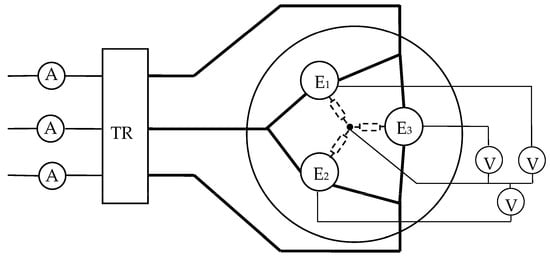
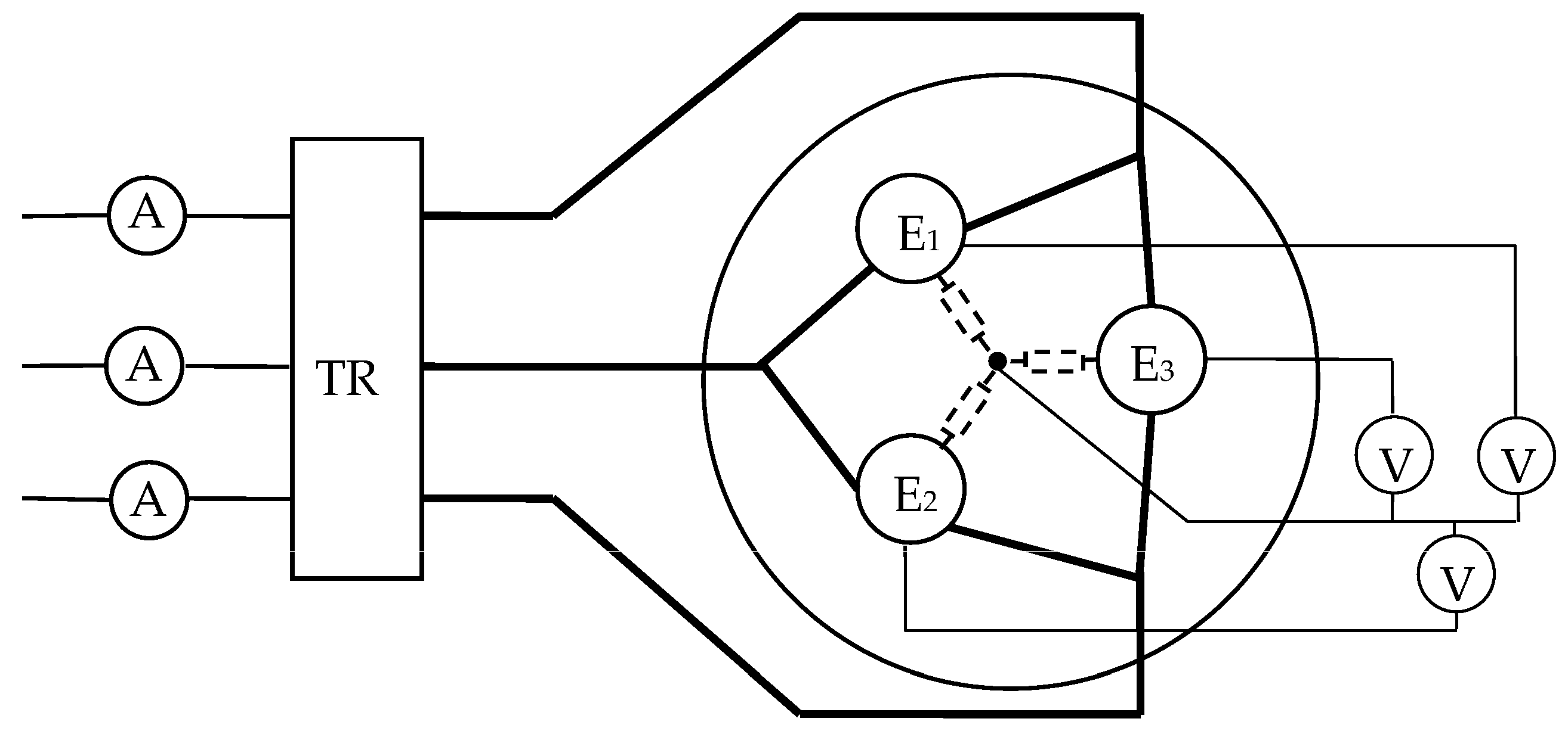
In order to verify the method proposed in this paper, example computations and measurements on a real submerged resistance-arc furnace were made. Experimental research was carried out at the Re Alloys Steelworks, on a resistance-arc furnace powered by an autotransformer with a power of 12 MVA. A simplified measurement system is shown in Figure 7. The measurements performed showed that the resistance of the charge for the FeSi75% ferrosilicon smelting process in the tested furnace is approximately [7,26].
Figure 7.
A simplified measurement system.
In the simulation tests, the package of sheets was divided into Neb sheets, and each sheet was divided into Nep of straight transverse elements with a rectangular cross-section. All flexible elements in the power supply system at each electrode are the same. It was assumed that the current density was constant along each straight section; then, the relationship between currents and voltage drops on individual elements was written in the form of the following subsystem of the system (9).
The elements of the system of Equation (77) constitute self- and mutual impedance matrices between elements with a rectangular cross-section, located arbitrarily relative to each other, and for one sheet they constitute a parallel system. For the i-th and j-th element of the straight section, km was located nearby—on one plate, inductance was determined by integrating over two parallel elements with a rectangular cross-section, according to the following formula:
The six-fold integration of formula (78) has an analytical form that can be expressed based on the so-called formulas given in publications [11,16]:
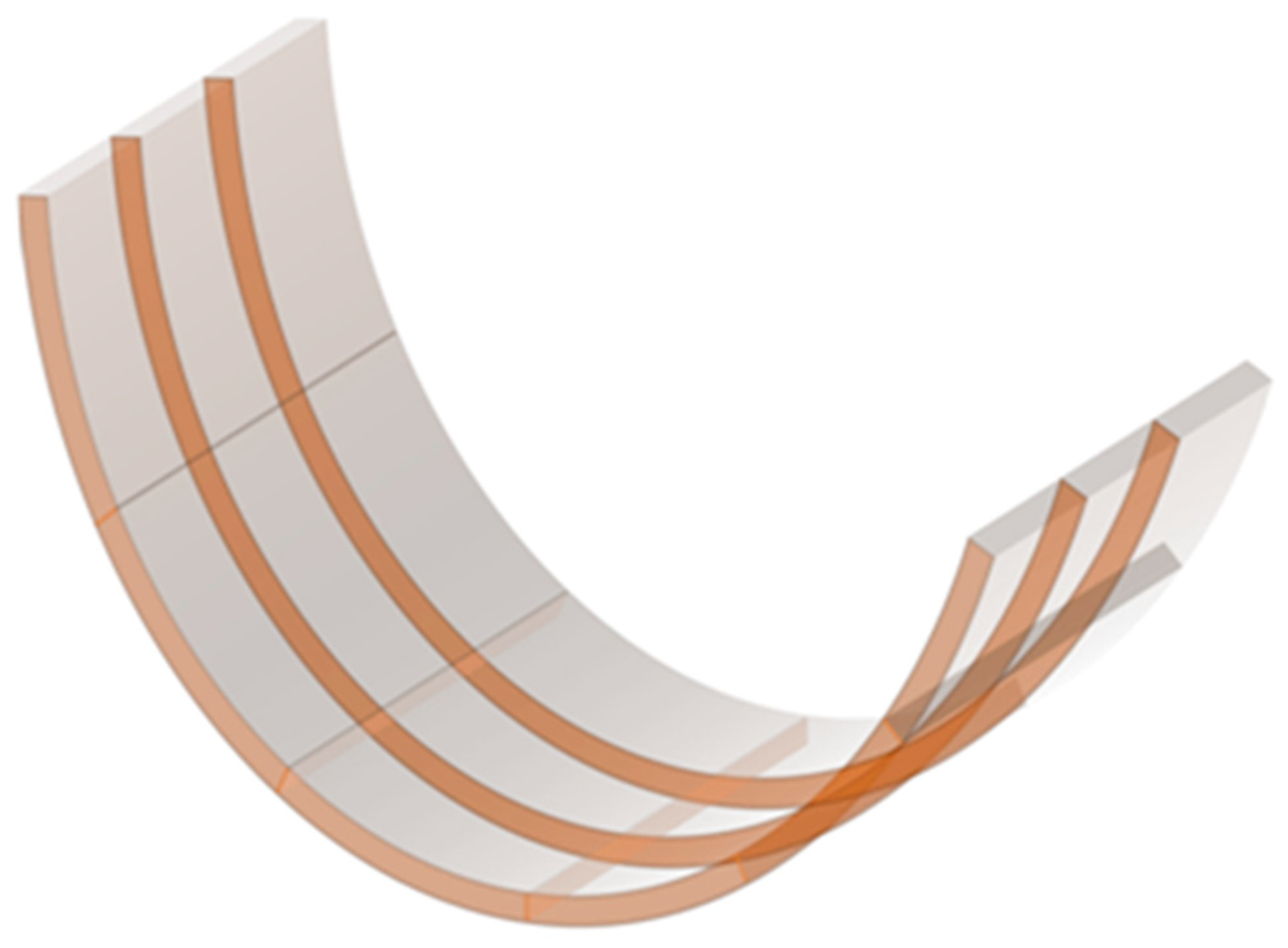
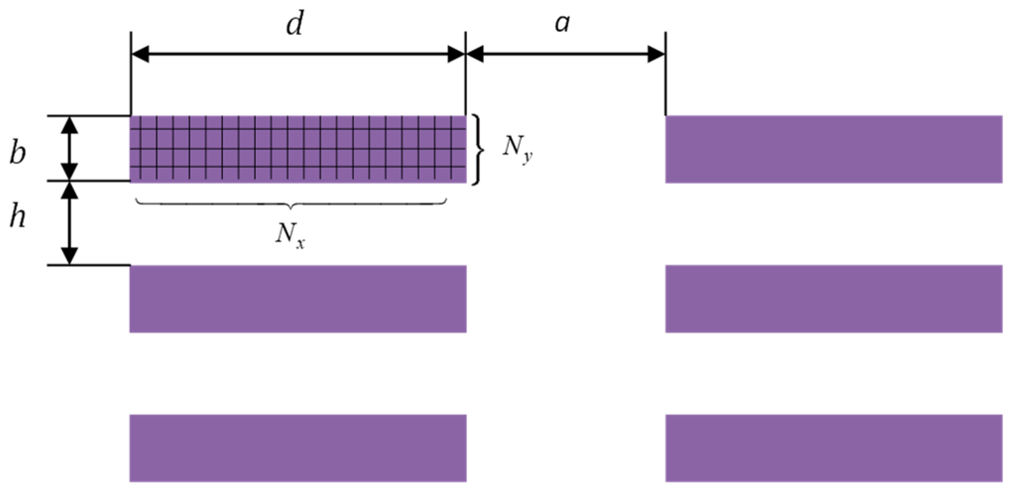
Due to the movement of the electrodes in relation to the fixed part of the track, a solution was introduced to connect these parts with a U-shaped package of sheets (Figure 8). Figure 9 shows a cross-section of the feed to the electrodes from only one phase connected to one side of the electrode. In the computational example, the skin effect and the proximity effect were examined for a parallel section of a given length of copper sheets.
Figure 8.
Example of division into elements of one sheet metal package.
Figure 9.
Cross-section of metal sheet packages.
As part of the simulation tests, a short network configuration was selected (Table 3), for which the self- and mutual impedance matrix was determined.
Table 3.
The dimensions in mm marked in Figure 6 adopted for calculations.
For the dimensions from Table 3, the self- and mutual impedance matrix, expressed in mΩ, for a short network without load, is expressed as follows:
The simulation tests carried out based on the designated algorithm and computational program showed the existence of such a geometric configuration of the bifilar high-current busduct, which for the entire short network guarantees the simultaneous achievement of approximately identical phase impedances of the short network, for which it is possible to achieve the maximum charge power for the charge resistance of approximately 1.2 mΩ.
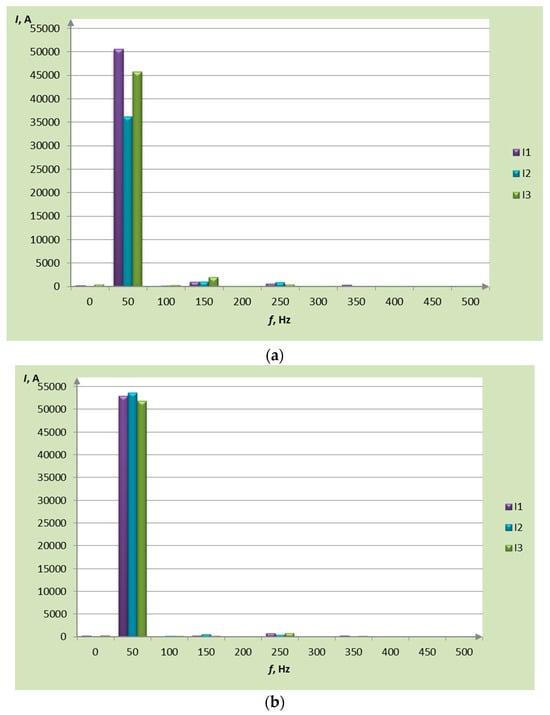
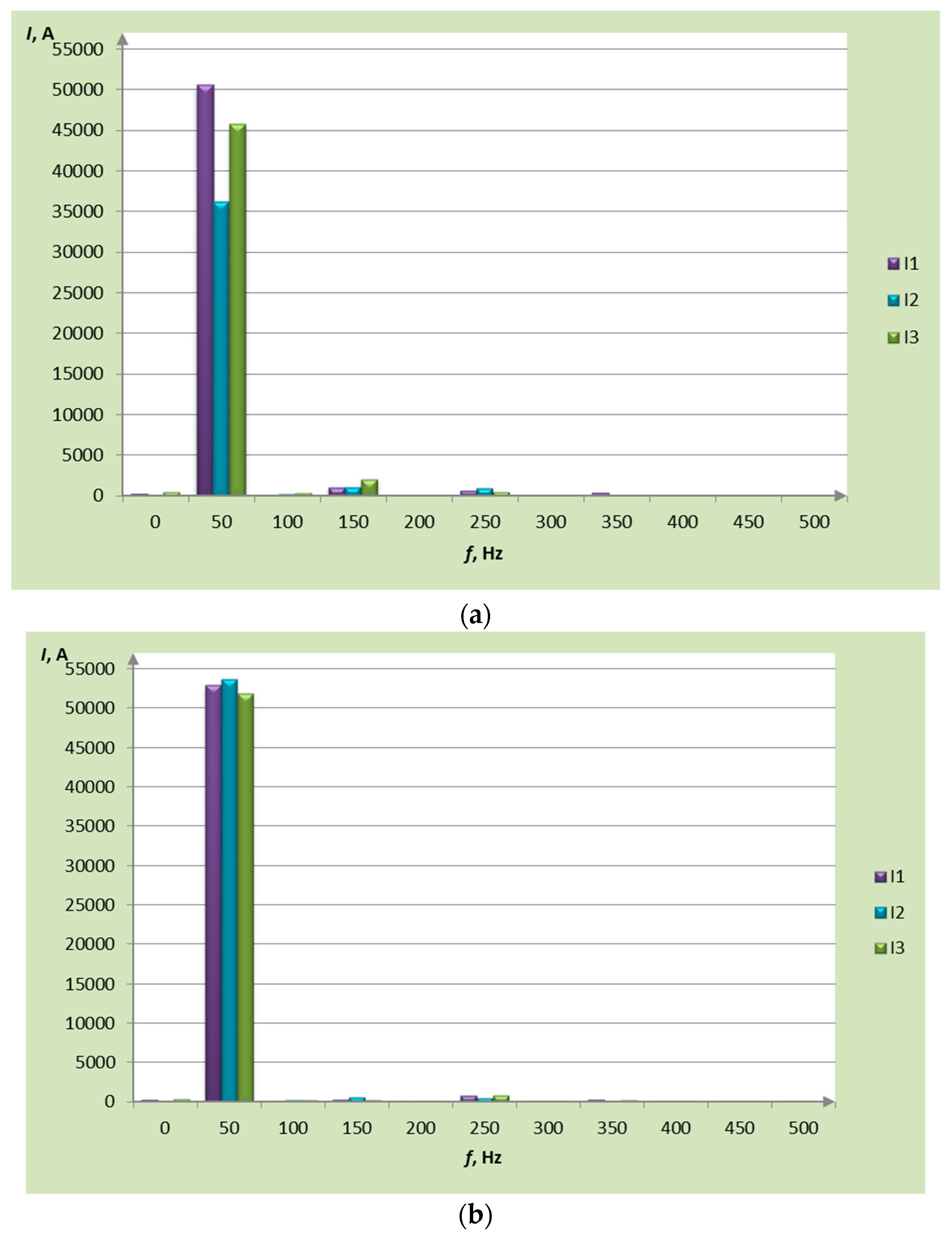
Therefore, the measurements were carried out for two operating states of the furnace, i.e., before modernization and after modernization. During the measurements, time courses of voltages and phase currents of the electrodes were recorded. Figure 10 shows the occurrence of current harmonics in both operating states. Before modernization, a symmetrical state of currents was not possible. A dead phase phenomenon then occurred, which significantly reduced the production efficiency.
Figure 10.
Distribution of harmonic currents in electrodes: (a) in the asymmetrical state and (b) in the symmetrical state.
During the asymmetric operation of the furnace, current asymmetry is noticeable, which is an unfavorable phenomenon for the operating transformers and causes difficulties in conducting the production process. In the symmetrical operation state, the current amplitudes are almost the same. The possibility of achieving a symmetrical operating condition of the furnace confirms the correctness of the theoretical considerations discussed, leading to the use of a technical solution in the form of an appropriately designed and constructed short network.
6. Conclusions
This paper shows that supporting the design of the bifilar high-current busduct of the resistance-arc furnace with the use of the non-linear programming method allows one to achieve symmetry in the load in the zone near the electrode. In addition, it has been shown that, if the furnace supply voltages are symmetrical, there exists a configuration of intertwined pipes of the bifilar busduct, for which, with the same resistances of the furnace’s electrode zone, the rms values of the electrode currents are the same. This means that the bifilar high-current busduct does not introduce asymmetry in the load of the individual phases of the furnace. Such a solution facilitates the production process of ferroalloys, because maintaining the same immersion of the electrodes in the bath of the furnace bath, which is important from the point of view of the smelting process, can be monitored by maintaining the same RMS current value of the individual phases. The equality constraint of non-linear programming (66) is decisive for the selection of appropriate magnetic couplings in the bifilar circuit of the furnace, which determines such possibilities. The objective function in the form of a tangent (69) makes it possible to obtain load symmetry with the smallest possible tan(φ) and thus the largest cos(φ) of the furnace. Such support for the design of the short network of the resistance-arc furnace was used in furnace 18 at the Re Alloys steelworks in Łaziska. The results of the measurements confirm the effectiveness of the proposed concept of supporting the design of bifilar busducts for resistance-arc furnaces for the production of ferroalloys.
Author Contributions
Conceptualization: B.B. and T.K.; methodology: B.B., Z.P., T.K., D.K. and T.S.; software: B.B. and T.K.; formal analysis: Z.P., D.K. and T.S.; writing—original draft preparation: B.B., Z.P. and T.S.; writing—review and editing: D.K. and T.S.; measurements: T.K.; supervision,: B.B., Z.P. and T.K. All authors have read and agreed to the published version of the manuscript.
Funding
This research received no external funding. The APC was funded by Czestochowa University of Technology.
Acknowledgments
We would like to extend our gratitude to the staff of Re Alloys company which helped in carrying out the measurements.
Conflicts of Interest
The authors declare no conflict of interest.
References
- Karbowniczek, M. Electric Arc Furnace Steelmaking; CRC Press: New York, NY, USA; Taylor & Francis Group: London, UK, 2021. [Google Scholar]
- Stewart, A.B. An Analysis of the Electrical Circuit of Submerged-Arc Furnaces. Ph.D. Thesis, University of Cape Town, Cape Town, South Africa, February 1980. [Google Scholar]
- Amadi, A. Modeling and Optimization of Three-Phase Submerged Arc Furnaces (SAF). Master’s Thesis, University of South Africa, Pretoria, South Africa, June 2012. [Google Scholar]
- Kadkhodabeigi, M. Modeling of Tapping Processes in Submerged Arc Furnaces. Ph.D. Thesis, University of Science and Technology, Trondheim, Norway, May 2011. [Google Scholar]
- Hauksdottir, A.S.; Gestsson, A.; Vesteninsson, A. Current control of a three-phase submerged arc ferrosilicon furnace. Control Eng. Pract. 2002, 10, 457–463. [Google Scholar] [CrossRef]
- Kurbiel, A. Arc Heating Equipments; WNT: Warsaw, Poland, 1988. [Google Scholar]
- Baron, B.; Świszcz, P.; Kraszewski, T. Some aspects of the analysis and the interpretation of electrical measurements of submerged arc-resistance furnace. Prz. Elektrotech. 2012, 88, 211–213. [Google Scholar]
- Barker, I.J.; Stewart, A.B. Inductive reactance, and the operation of large submerged-arc furnaces. J. S. Afr. Inst. Min. Metall. 1980, 80, 123–128. [Google Scholar]
- Hocine, L.; Yacine, D.; Kamel, B.; Samira, K.M. Improvement of electrical arc furnace operation with an appropriate model. Energy 2009, 34, 1207–1214. [Google Scholar] [CrossRef]
- Grabowski, D.; Klimas, M. New directions in electric arc furnace modeling. Arch. Electr. Eng. 2023, 72, 157–172. [Google Scholar]
- Wciślik, M.; Strząbała, P. Physical model of power circuit of three-phase electric arc furnace. Prz. Elektrotech. 2018, 4, 103–106. [Google Scholar] [CrossRef]
- Sawicki, A. Electric arc models with non-zero residual conductance and with increased energy dissipation. Arch. Electr. Eng. 2021, 70, 819–834. [Google Scholar]
- Teklić, A.T.; Filipović-Grčić, B.; Pavić, I. Modelling of three-phase electric arc furnace for estimation of voltage flicker in power transmission network. Electr. Power Syst. Res. 2017, 146, 218–227. [Google Scholar] [CrossRef]
- Samet, H.; Sadeghi, R.; Ghanbari, T. Time-varying frequency model for electric arc furnaces. IET Gener. Transm. Distrib. 2022, 16, 1122–1138. [Google Scholar] [CrossRef]
- Dietz, M.; Grabowski, D.; Klimas, M.; Starkloff, H.J. Estimation and analysis of the electric arc furnace model coefficients. IEEE Trans. Power Deliv. 2022, 37, 4956–4967. [Google Scholar] [CrossRef]
- Fernando Martell, F.; Izaguirre, A.; Macias, M. CPC Power Theory for Analysis of Arc Furnaces. Prz. Elektrotech. 2016, 92, 138–142. [Google Scholar]
- Łukasik, Z.; Olczykowski, Z. Estimating the Impact of Arc Furnaces on the Quality of Power in Supply Systems. Energies 2020, 13, 1462. [Google Scholar] [CrossRef]
- Kovaćić, M.; Stopar, K.; Vertnik, R.; Šarler, B. Comprehensive Electric Arc Furnace Electric Energy Consumption Modeling: A Pilot Study. Energies 2019, 12, 2142. [Google Scholar] [CrossRef]
- Lee, B.; Sohn, I. Review of Innovative Energy Savings Technology for the Electric Arc Furnace. JOM 2014, 66, 1581–1594. [Google Scholar] [CrossRef]
- Olczykowski, Z. Electric Arc Furnaces as a Cause of Current and Voltage Asymmetry. Energies 2021, 14, 5058. [Google Scholar] [CrossRef]
- Jagieła, K.; Gała, M.; Kępiński, M. Asymmetry of parameters of the bifilar high-current circuits supplying the arc-resistance furnace. Prz. Elektrotech. 2017, 93, 84–88. [Google Scholar]
- Lozynskyy, A.; Kozyra, J.; Łukasik, Z.; Kuśmińska-Fijałkowska, A.; Kutsyk, A.; Paranchuk, Y.; Kasha, L. A Mathematical Model of Electrical Arc Furnaces for Analysis of Electrical Mode Parameters and Synthesis of Controlling Influences. Energies 2022, 15, 1623. [Google Scholar] [CrossRef]
- Luckins, E.K.; Oliver, J.M.; Please, C.P.; Sloman, B.M.; Valderhaug, A.M.; Van Gorder, R.A. Modelling alternating current effects in a submerged arc furnace. IMA J. Appl. Math. 2022, 87, 492–520. [Google Scholar] [CrossRef]
- Dancis, Y.B. Short Network and Electrical Parameters of Electric Arc Furnaces; Handbook; Metallurgiya: Moscow, Russia, 1974. (In Russian) [Google Scholar]
- Strunsky, B.M. Short Electric Network of Electric Arc Furnaces; GN-TIL: Moscow, Russia, 1962. (In Russian) [Google Scholar]
- Kraszewski, T. Application of Integral Equations to Determine Electrical Parameters of Bifilar Busducts of Electric Furnaces. Ph.D. Thesis, Silesian University of Technology, Gliwice, Poland, 2013. (In Polish). [Google Scholar]
- Piatek, Z. Self and Mutual Impedances of a Finite Length Gas Insulated Transmission Line (GIL). Electr. Power Syst. Res. 2007, 77, 191–203. [Google Scholar] [CrossRef]
- Piątek, Z.; Baron, B. Exact closed form formula for self inductance of conductor of rectangular cross section. Prog. Electromagn. Res. M 2012, 26, 225–236. [Google Scholar] [CrossRef]
- Hoer, C.; Love, C. Exact Inductance Equations for Rectangular Conductors with Application to More Complicated Geometries. J. Res. Natl. Bur. Stand. Sect. C Eng. Instrum. 1965, 26, 127–137. [Google Scholar] [CrossRef]
- Kolanska-Pluska, J.; Jabłoński, P.; Piątek, Z. Numerical Method of Computing the Impedance of a Twin High Current Busduct of Rectangular Hollow Conductors. Prog. Electromagn. Res. M 2014, 34, 9–17. [Google Scholar] [CrossRef]
- Kusiak, D. The Magnetic Field and Impedances in Three-Phase Rectangular Busbars with a Finite Length. Energies 2019, 12, 1419. [Google Scholar] [CrossRef]
- Grover, F.W. Inductance Calculations; Dover Publications, Inc.: New York, NY, USA, 1973. [Google Scholar]
- Press, W.H.; Teukolsky, S.A.; Vetterling, W.T.; Flannery, B.P. The Art of Scientific Computing. In Numerical Recipes, 3rd ed.; Cambridge University Press: Cambridge, UK, 2007. [Google Scholar]
- Hestenes, M.R.; Stiefel, E. Method of conjugate gradient for solving linear system. J. Res. Natl. Bur. Stand. 1952, 49, 409–436. [Google Scholar] [CrossRef]
- Hestenes, M.R. Multiplier and gradient methods. J. Optim. Theory Appl. 1969, 4, 303–320. [Google Scholar] [CrossRef]


Disclaimer/Publisher’s Note: The statements, opinions and data contained in all publications are solely those of the individual author(s) and contributor(s) and not of MDPI and/or the editor(s). MDPI and/or the editor(s) disclaim responsibility for any injury to people or property resulting from any ideas, methods, instructions or products referred to in the content. |
© 2023 by the authors. Licensee MDPI, Basel, Switzerland. This article is an open access article distributed under the terms and conditions of the Creative Commons Attribution (CC BY) license (https://creativecommons.org/licenses/by/4.0/).