Abstract
A brush seal is a type of contact sealing technology that generates a great amount of heat during operations. The heat can affect the seal’s performance and lifespan. To study the brush seals’ temperature distribution, a new model considering the anisotropic heat transfer effect is established in this paper. The friction heat effect at the bristles’ tip is studied. The temperature field and leakage rates are obtained by using combined finite element analysis (FEA)-computational fluid dynamics (CFD) analysis and the anisotropic heat transfer theory. The influence of operating and structural parameters on the temperature field and the sealing properties of the brush seal are investigated. It is shown that the value of the rotation rate and the interference can cause the temperature of the brush seal to increase. The pressure difference enhances the convective heat transfer from the brush seals. While the temperature at the bristles’ tip increases, the radial average temperature of the bristles decreases significantly. In the case of a small pressure difference, the fence’s height can increase the windward area, leading to stiff bristles and resulting in a temperature increase at the bristles’ tip; however, the effective flow area increases, resulting in an acceleration of the radial temperature’s decrease. To summarize, the porous medium model of anisotropic heat transfer provides a new method for studying brush seals, and it can reflect the temperature distribution and leakage performance of brush seals.
1. Introduction
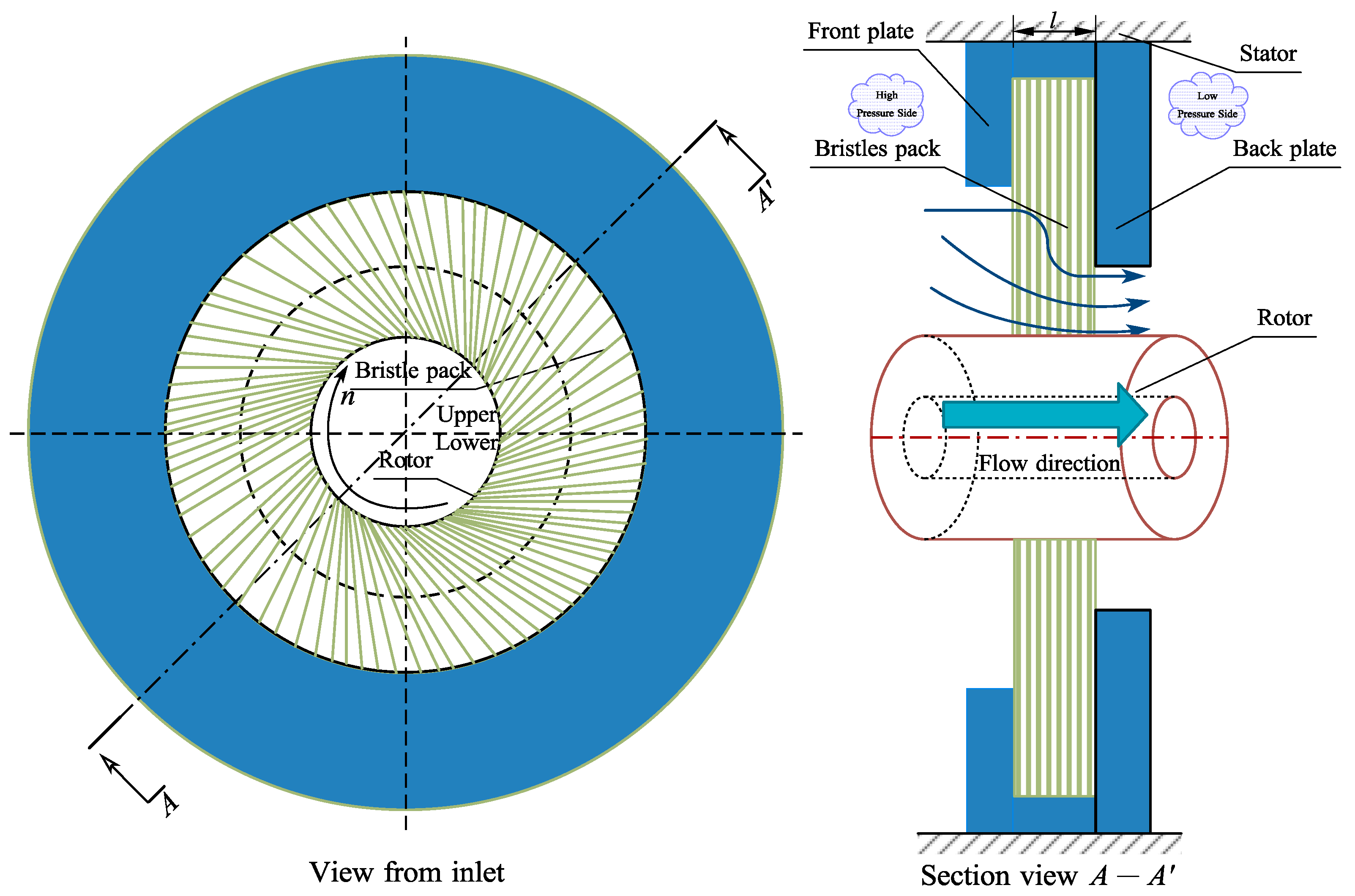
Brush seals comprise an efficient dynamic sealing technology with excellent sealing performance, and it is widely used in aero-engines and industrial gas turbines [1,2]. The traditional structure of a brush seal is illustrated in Figure 1, consisting of a bristles pack, a front plate, and a back plate. To ensure good sealing performance, the bristle’s tip is normally kept in contact with the rotor’s surface. When the rotor is running, friction heat and temperature increase effects are produced due to the excessive rotation rate, which affects the sealing performance and safe operation of the brush seal. Therefore, it is of great scientific significance and engineering value to study the friction heat effect of brush seals.
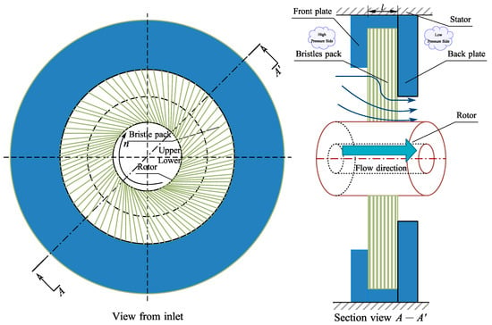
Figure 1.
The traditional structure of brush seals.
International and national scholars have studied the leakage rate and friction heat effect of brush seals using experimental and numerical analysis, and numerous valuable conclusions have been obtained. Manuel et al. [3] studied the influence of fence heights on the stiffness, leakage rate, and friction loss of brush seals and concluded that the fence’s height is essential for the brush seal. Bowen et al. [4,5] constructed a large-scale brush seal to study flow characteristics and pressure distributions in the bristle pack, and the results can be used in the establishment of porous medium models. Markus [6] designed a test rig to study the friction heat of brush seals, and the test rig can measure the temperature distribution of the rotor. Li et al. [7] studied the width of the pressure balance chamber of brush seals and concluded that the leakage performance and elastic resilience of brush seals are the best when the width is 0.4 mm. Duran [8] proposed an analytic formula for the contact force of the bristle’s tip and analyzed the frictional heat rate of the brush seal.
A flow analysis model of brush seals can be divided into three types: the tube bank model, the porous medium model, and the simple effective thickness model. The simple effective thickness model [9] can calculate the maximum leakage rate according to the structural and operating parameters of the brush seal by applying the mathematical model. The model is highly dependent on the experience and cannot reflect the flow inside the bristles. The tube bank model assumes that the air travels through the closely arranged staggered-array tube bank, and two sub-models are included: 2-dimensional and 3-dimensional tube bank models. The 2-dimensional model cannot reflect the anisotropic flow in the bristle pack [10], and a 3-dimensional model [11] is too complex for establishing a model and solving computational convergence. The bristles closely resemble a random arrangement, and the tube bank model has limitations.
According to the structural features of the bristles and the sheet flow of the air in the bristle pack, the bristle pack can be seen as a porous medium zone. Bayley et al. [12] proposed using a brush seal as the anisotropic porous medium model by implementing the Darcy equation. The Darcy equation is based on a linear equation and only considers the viscous resistance of the flow and ignores inertial resistance. Chew et al. [13] established a porous medium model based on the Darcy–Forcheimer equation, which considers the influence of kinetic energy. Qiu et al. [14] established a formula for calculating the resistance coefficient based on the Eugen equation. Song et al. [15] proposed a method for calculating the resistance coefficient by simulating a 2-dimensional tube bank model and considering the compressibility of gas. The porous medium model’s solution can be easily obtained such that it is widely used in the leakage, heat transfer, and rotor dynamics analyses of brush seals. Because the porous medium model is easy to compute, the model is always used with respect to structural improvements during turbine stages [16].
Many researchers studied the dynamic performance and heat transfer characteristics of brush seals based on the porous medium model. With regard to the heat transfer characteristic of brush seals, Dogu et al. [17] analyzed the temperature field of brush seals at different operating parameters by using the porous medium model. Zhang et al. [18] analyzed the influence of the back plate structure on the temperature field of the brush seal by combining the porous medium model and the finite element model. Zhang [19] compared the local temperature equilibrium model (LTE) and the local temperature non-equilibrium model (LTNE) to study the bristle pack’s temperature distribution and concluded that the local temperature non-equilibrium model is more suitable for brush seals. Manuel et al. [20] applied the porous medium model to study the heat flux distribution on the rotor during the rubbing of brush seals.
Haruki [21] studied the heat transfer of metal fiber porous materials and found that the effective thermal conductivity is anisotropic. As heat transfer mainly occurs along the bristles, Xia [22] considered that the heat conduction in the bristle pack is anisotropic and conducted an assessment on thermal conductivity, concluding that thermal conductivity can influence the prediction of seal temperatures and leakage rates. Meanwhile, the heat built up in the bristle’s tip can lead to the bristle fusion, reducing the seal performance and endangering the operation of the aero-engine. Therefore, it is essential to establish an anisotropic heat transfer model for brush seals. However, in the temperature distribution study of brush seals, the isotropic effective thermal conductivity model is normally used when establishing the porous medium model, which ignores the directivity of heat conduction and the complexity of heat transfer.
Therefore, the complexity of heat transfer is considered in this paper, and a new model is proposed, considering the anisotropic heat transfer in the bristle pack. In this paper, the porous medium model is established to consider the anisotropic heat transfer of brush seals using FLUENT’s user-defined function (UDF). The finite element analysis (FEA)-computational fluid dynamics (CFD) method is used to analyze the impact of operating and structural parameters on the leakage rate and temperature field. The research in this paper provides a new method for studying the heat transfer mechanism of brush seals and provides resources for the performance analysis of brush seals.
2. Numerical Method
2.1. Frictional Heat Calculation
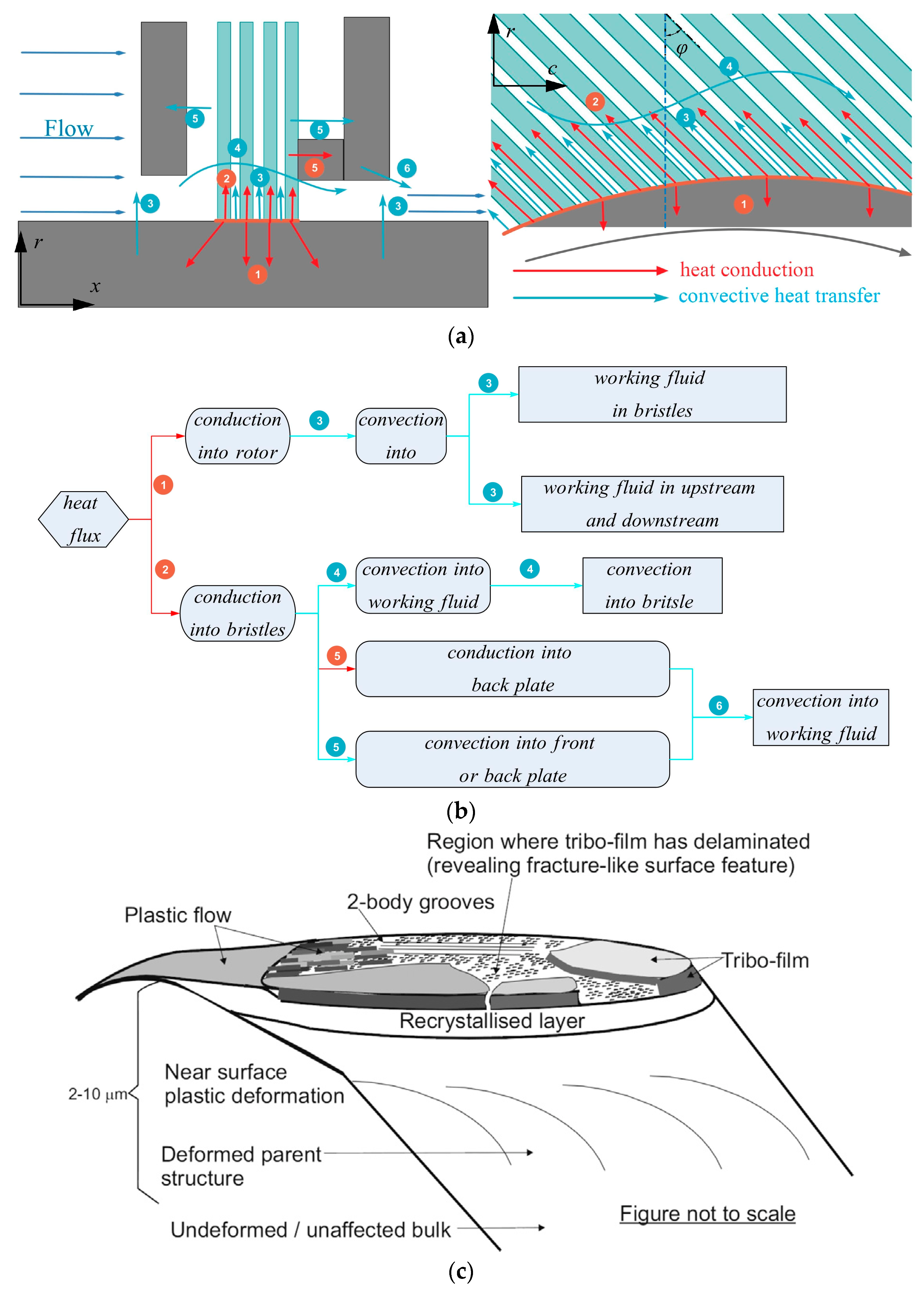
In the running of brush seals, the friction heat between the bristle pack and the rotor is assumed to be the annular heat source, and heat is transferred to the bristles and rotor via conductive heat transfer, as shown in Figure 2a. While heat flux is transferred from the bristles’ tip to the bristles’ roots via conductive heat transfer, the quality of heat shift exchanges is carried out by the working medium’s bristles. The heat exchange also occurs in the back plate and bristles via conductive heat transfer. Figure 2b shows the detailed heat transfer process. When all solids and fluids reach thermal equilibrium, the temperature field is stable. Frictional heat generation, Q, can be calculated using the following formula:
where μ is the bristle–rotor friction coefficient; γh is the friction work proportion relative to thermal energy; Nb is the normal contact force between the bristle tip and the rotor; V is the velocity of the rotor surface, m/s; n is the rotational speed, rpm; Di is the inner diameter of the rotor, mm.
During the sliding friction process, friction energy is also used to generate elastic fracture, shear melting, and plastic flow [23], and 9~16% of the process is used to wear and form a new surface. The friction surface characteristics of the bristle tip are shown in Figure 2c [22]. According to Figure 2c and Wang’s study [24], γh is selected as 85%.
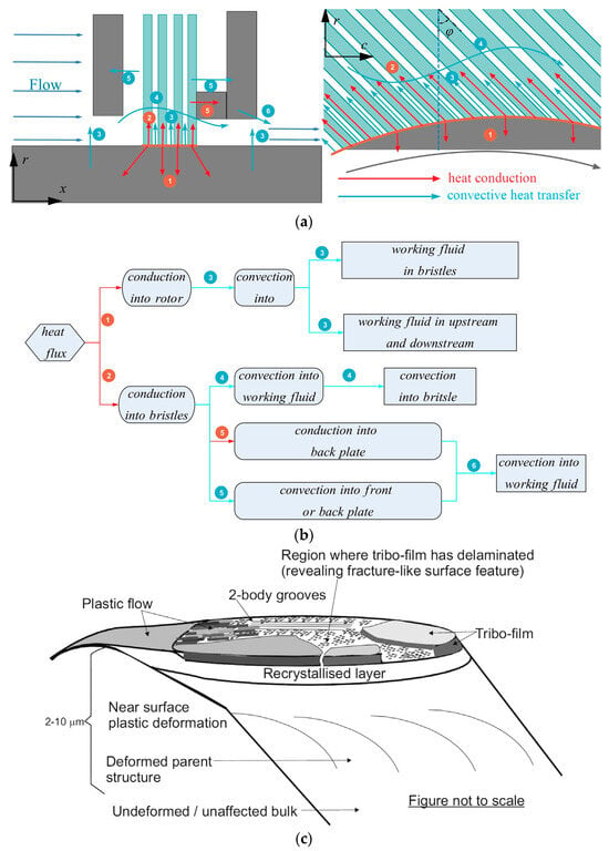
Figure 2.
The heat transfer mechanism of brush seals: (a) heat transfer diagram; (b) flow chart of heat transfer; (c) wear surface characteristics of the bristles’ tip [25].
Figure 2.
The heat transfer mechanism of brush seals: (a) heat transfer diagram; (b) flow chart of heat transfer; (c) wear surface characteristics of the bristles’ tip [25].
In this paper, the boundary condition of the constant heat flux is used on the rotor’s surface in FLUENT. Thus, the constant heat flux, q, is defined by the following formula:
where A is the contact area between the bristle pack and the rotor, α is the distribution ratio of the heat flux entering into the bristle pack, and α between the two kinds of metal materials is 40~60% [26]; thus, α is 50% in this study.
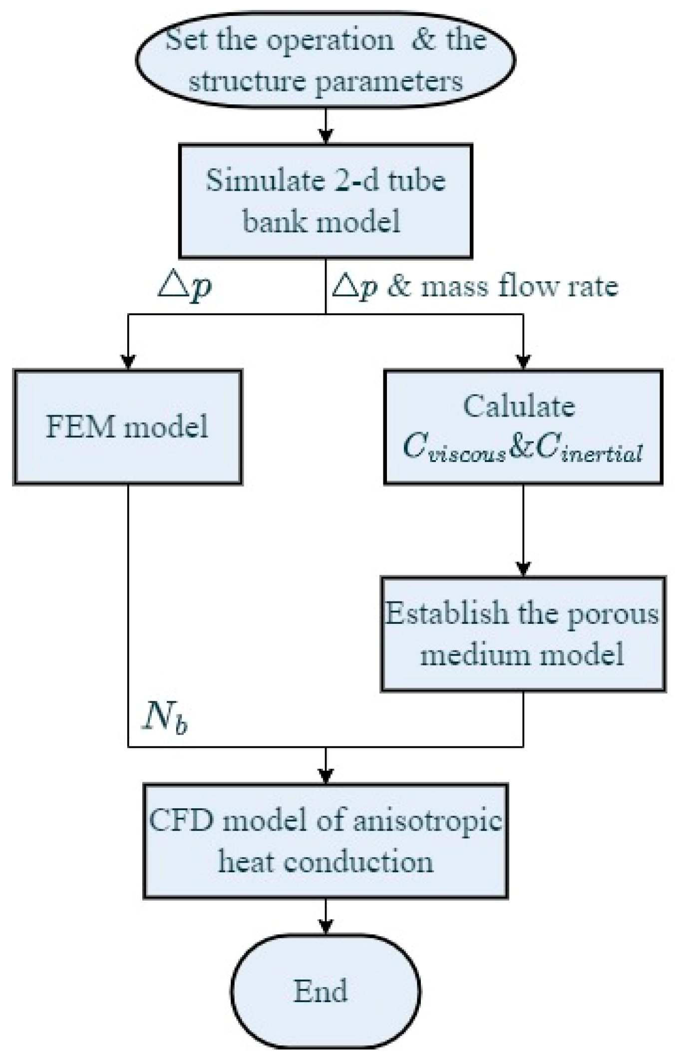
The porous medium model is established to simulate the flow and heat transfer characteristics in the brush seal based on Song’s study [15], which considers anisotropic heat conduction characteristics. The pressure difference between the upstream and downstream areas must affect the stiffness of the bristle pack. In this paper, the FEA model is used to calculate the normal contact force, considering the influence of the pressure difference by ANSYS, and the CFD model is used to calculate the temperature field and the leakage rate. Then, force Nb is utilized to obtain frictional heat flux q. The detailed method and technological process are shown in Figure 3.
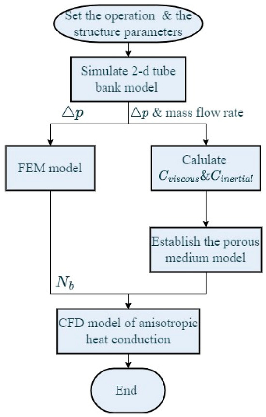
Figure 3.
The flow chart of the numerical simulation.
2.2. Numerical Simulation of the CFD Model
The FLUENT software applied in CFD technology is used to simulate the flow and heat transfer characteristics of brush seals. When the working fluid crosses through the minute pore space of the bristle pack, flow conduction is complex and disordered, and it is similar to the flow in porous materials. Meanwhile, the flow’s velocity is so fast that the inertial resistance effect cannot be ignored. Therefore, the Darcy–Forchheimer model is used in the numerical simulation. Due to the axisymmetric structure of brush seals, the numerical model is set as the two-dimensional axisymmetric model, and the governing equation of the flow and heat transfer of brush seals is as follows.
The continuity equation is shown in Equation (3):
where ρ is the density of fluid; u is the flow velocity; x and r are the axial and the radial coordinates, respectively.
For the two-dimensional axisymmetric model, the axial and radial momentum equation is as follows:
where μf is the viscosity of fluid; Sx and Sr are the source terms in the x and r directions.
Here, Ci,viscous and Ci,inertial are the viscous and inertial resistance coefficients in different directions. Equation (7) is the computational formula of resistance coefficients in the x direction; m is the mass flow rate of the 2-dimensional tube bank model. The detailed method is shown in the literature [15], and the resistance coefficients of brush seals are shown in Table 1 [15].

Table 1.
Viscous and inertial resistance coefficients [15].
The state equation of ideal gas is Equation (8):
where R is the gas constant, 287.1 J/(kg·K); T is the temperature.
The local temperature equilibrium (LTE) model and the local temperature non-equilibrium (LTNE) model are widely used in the heat transfer mechanism of porous media. Generally, the accuracy of the LTNE model is considered higher than the LTE model. However, when the effect of heat convection is powerful enough, the temperature difference between the solid and fluid phases can be ignored, and the LTE model is considered quick and accurate [27]. From Li’s study, which is based on the LTNE model [14], fluid and solid temperatures are almost equal in the bristle pack, and the temperature fields of the fluid and solid phases are very similar. Therefore, the heat transfer of the porous medium model is based on the local temperature equilibrium model [28,29]. The energy equation of the bristle pack is described using Equation (9):
where Ef is the fluid energy in the porous medium zone; ke is the effective thermal conductivity of the porous medium zone.
Jagjiwanram [30] studied the effective thermal conductivity of the two-dimensional porous medium, and it was observed that β, which is the angle between the direction of heat flow and the plane skeleton layer, is an essential factor for ke. ke is indicated in Equation (10).
According to the theory of heat transfer in the porous medium, kmax and kmin are expressed as follows:
where ks and kf are the solid and fluid phases, respectively; ε is the porosity of the bristle pack.
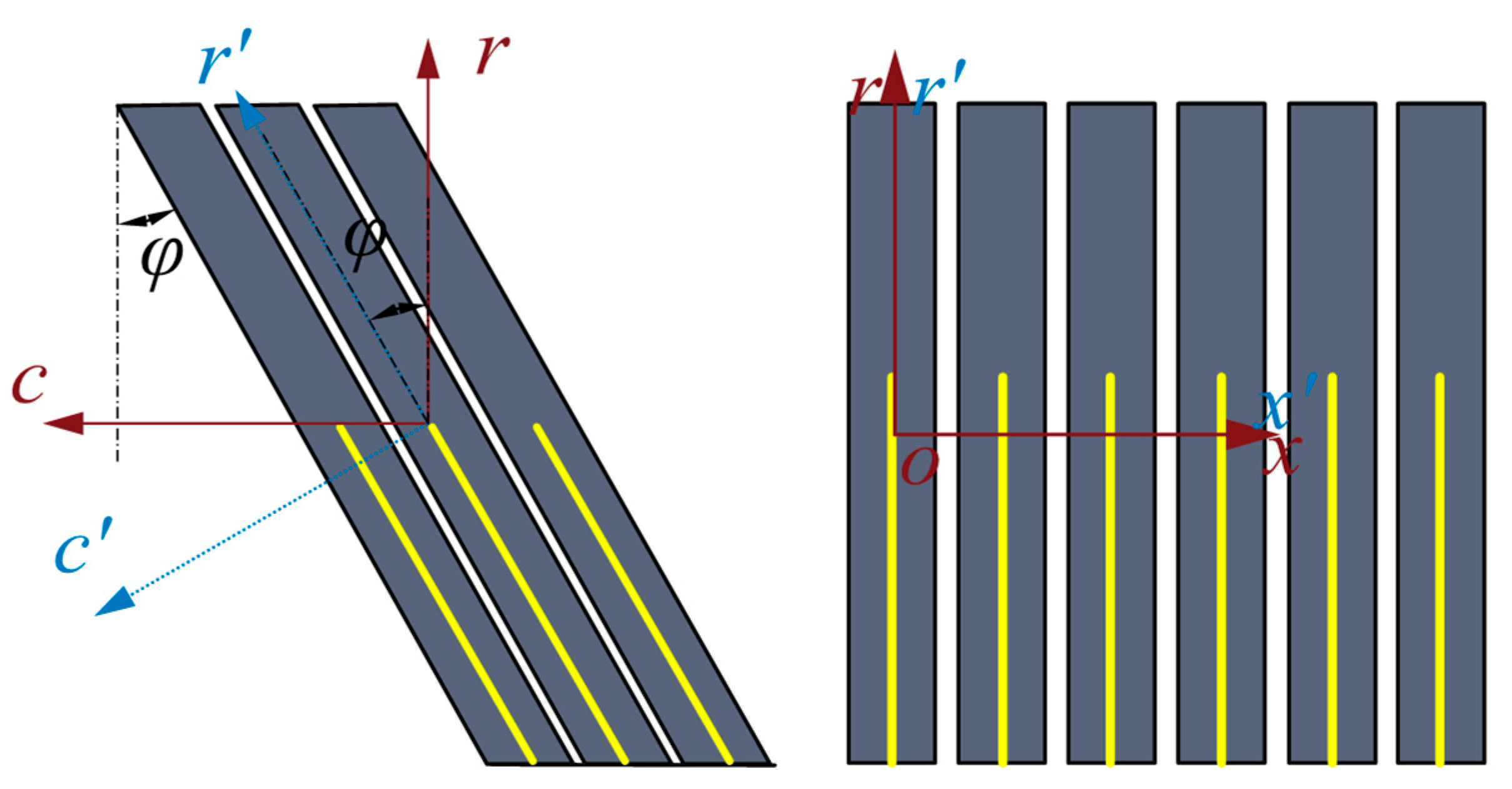
Therefore, inclination angle φ between the bristle and rotor affects the effective thermal conductivity, and the relationship is shown in Figure 4. ke can be calculated as follows:
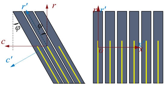
Figure 4.
The heat transfer of the weld brush seal in the computational coordinate system.
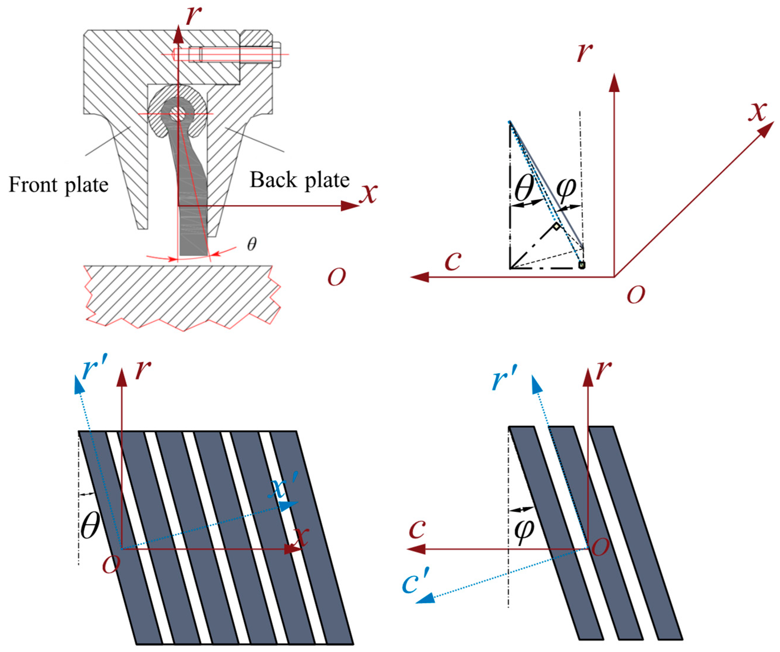
Due to manufacturing costs and the inhibiting effect of the stiffening effect, the Motoren- und Turbinen-Union (MTU) corporation designed a new type of brush seal called MTU brush seal [31]. The MTU brush seal is also commonly used. There is a clamping inclination angle, θ, with the exception of the installation inclination angle φ, as shown in Figure 5. The bristles have an angle, θ, between the r-axis. According to the anisotropic heat transfer model [28] and the MTU brush seal structural characteristics, the equation of anisotropic effective thermal conductivity can be written as follows:
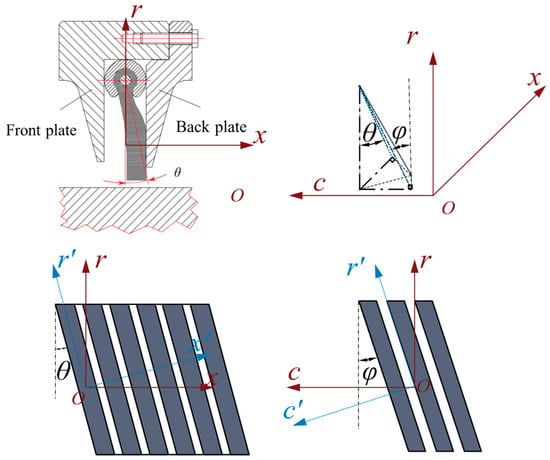
Figure 5.
Schematic diagram of the heat transfer mechanism of the MTU brush seal [31,32].
When θ is 0°, Equation (13) is equal to Equation (12) and can be used to study the weld brush seal. Therefore, Equation (13) is a universal equation with respect to the anisotropic effective thermal conductivity for brush seals. In this paper, Equation (12) is used to study the weld brush seal.
2.3. FEA Model
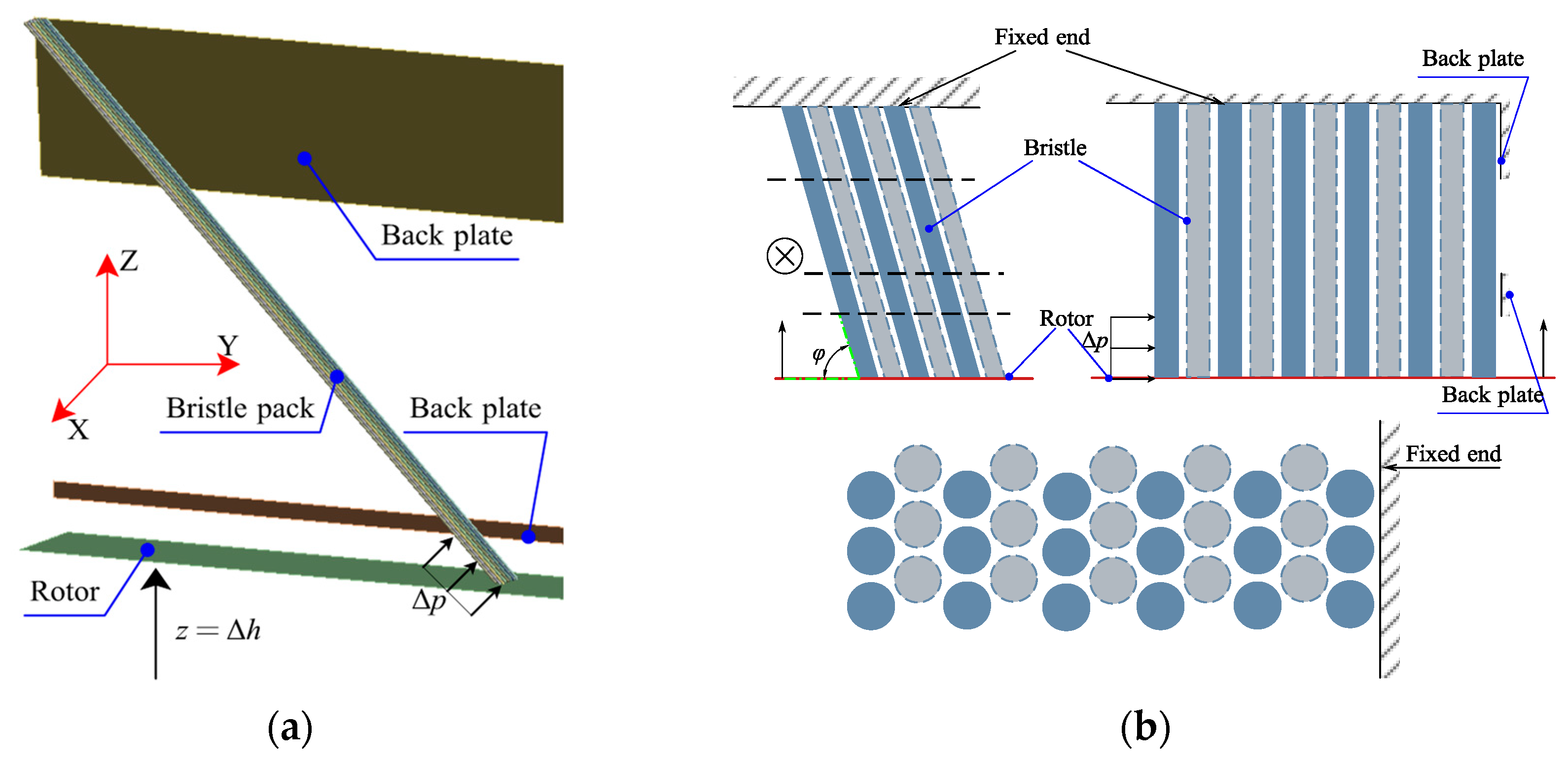
As shown in Figure 6, the nonlinear finite element contact model, which is simplified according to the structure of brush seals [33], is established to solve the normal contact force Nb between the bristle pack and the rotor surface. Because the bristle pack exhibits a cyclic symmetrical structure in the circumferential direction, three rows are set in the Y direction, and eleven rows are set in the X direction. The roots of the bristles are fixed. The pressure difference between upstream and downstream Δp from the 2d tube bank model is imposed at every bristle using the liner aerodynamic load method. The rotors and back plate are considered rigid bodies. The rotor is only free in the Z direction, and the back plate is fixed. Finally, friction heat flux q is calculated using Nb and Equation (1), and it is regarded as a boundary condition added to the porous medium model in Section 2.2, as shown in Figure 7. Because the rotational speed can cause bristle vibration, the nonlinear FEA model has difficulty converging. Therefore, the rotational speed is not usually considered in the brush seal and finger seal contact model [33,34,35].
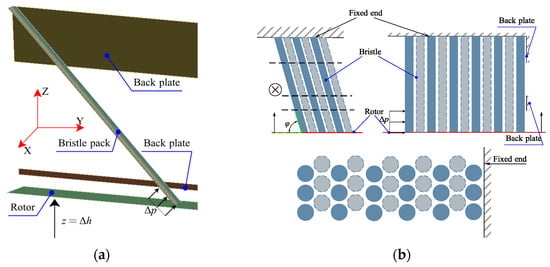
Figure 6.
FEA model (a) and boundary conditions (b).
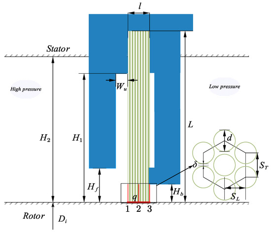
Figure 7.
Computational domain of the brush seal.
The bristles are set as the Beam188 element. The bristle to the rotor, bristles to adjacent bristles, and the last bristle to back plate contact pairs comprise the node–surface contact, beam–beam parallel contact, and beam–beam cross contact, respectively. The friction coefficients of these friction pairs are 0.24, 0.2, and 0.28 [36]. In this paper, the material of bristles is Haynes 25 [37]; its elastic modulus E is 206 GPa and Poisson’s ratio is 0.3 [38]. The FEA model is solved using ANSYS [38,39].
2.4. CFD Model and Structure of the Brush Seal
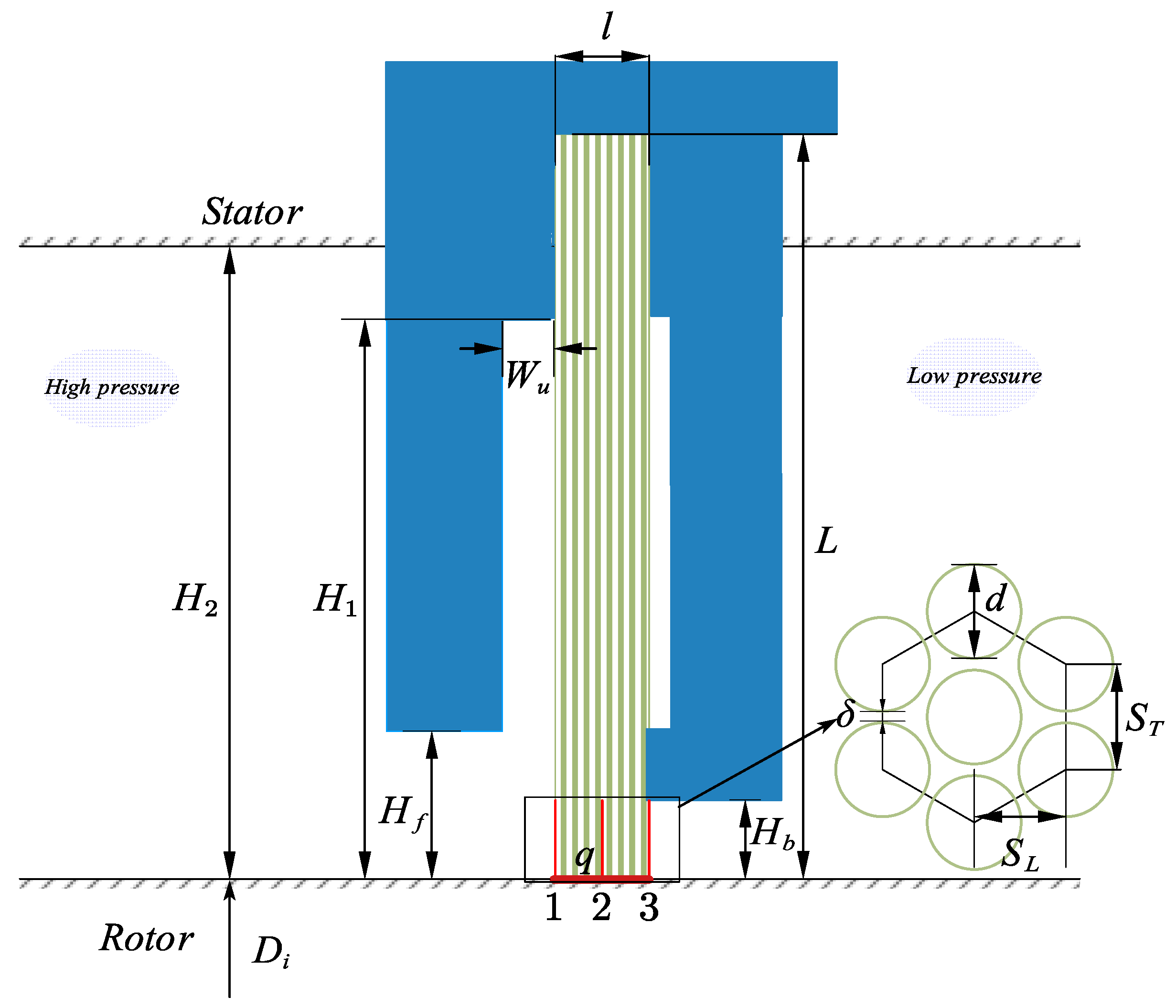
The numerical model is established according to the brush seal of KIST [40,41,42], and the detailed structural parameters are shown in Table 2. The computational domain is divided into the solid, fluid, and porous areas of the bristle pack zone, as shown in Figure 7. The solid zone includes the front and back plates. The operation parameters are shown in Table 3. The pressure-based 2d axisymmetric swirl model is used in FLUENT, and the RNG k-epsilon model is used as the turbulence model. The coupled method and the second-order upwind difference are adopted in the governing equations. The inflow and outflow boundary conditions are the pressure inlet and pressure outlet, respectively. The rotor is given a specific rotational speed and heat flux value. The working medium is air, which is considered as the ideal gas. When the pressure difference is higher than 0.02 MPa, the compressibility of gas cannot be ignored. Therefore, air is regarded as the ideal gas. We used 410 stainless steel in the solid phase. Effective thermal conductivity is added to the model via UDF. The thermophysical properties of these materials are shown in Table 4.

Table 2.
Structure parameters of the brush seal [40,41].

Table 3.
Operational parameters.

Table 4.
Thermophysical properties.
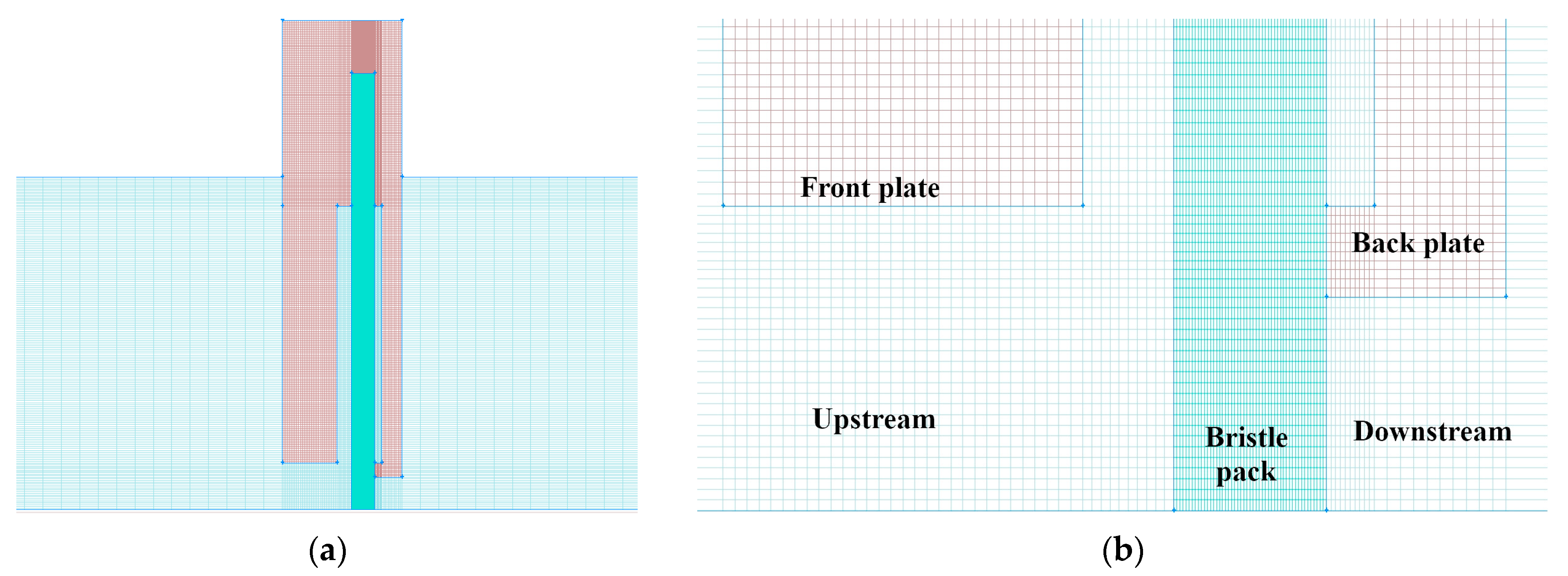
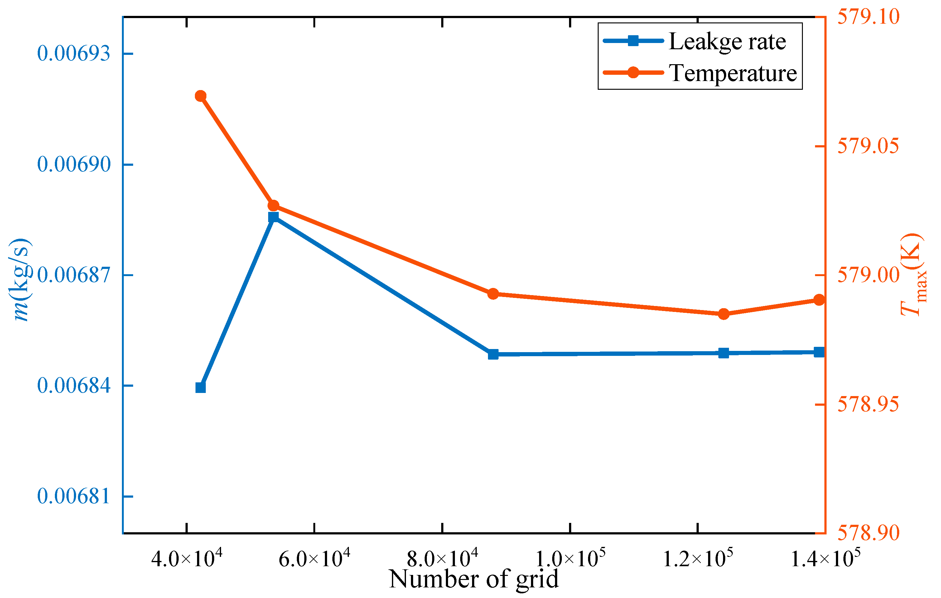
Figure 8 is the computation grid of the CFD model, which is generated using the structured grid. In order to prove the model’s reliability, grid independence is shown in Figure 9. When the number of grids is larger than 90,000 grids, the model satisfies the requirement of grid independence. After overall considerations, 130,000 grids are used to establish the CFD model in order to simulate the characteristics of the leakage rate and heat transfer.
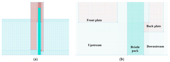
Figure 8.
Computational grid of the brush seal: (a) structured grids of the computational domain; (b) detailed grid.
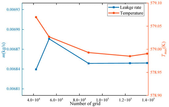
Figure 9.
Grid independence verification.
3. Numerical Simulation Results and Discussion
3.1. Validation of the Numerical Simulation
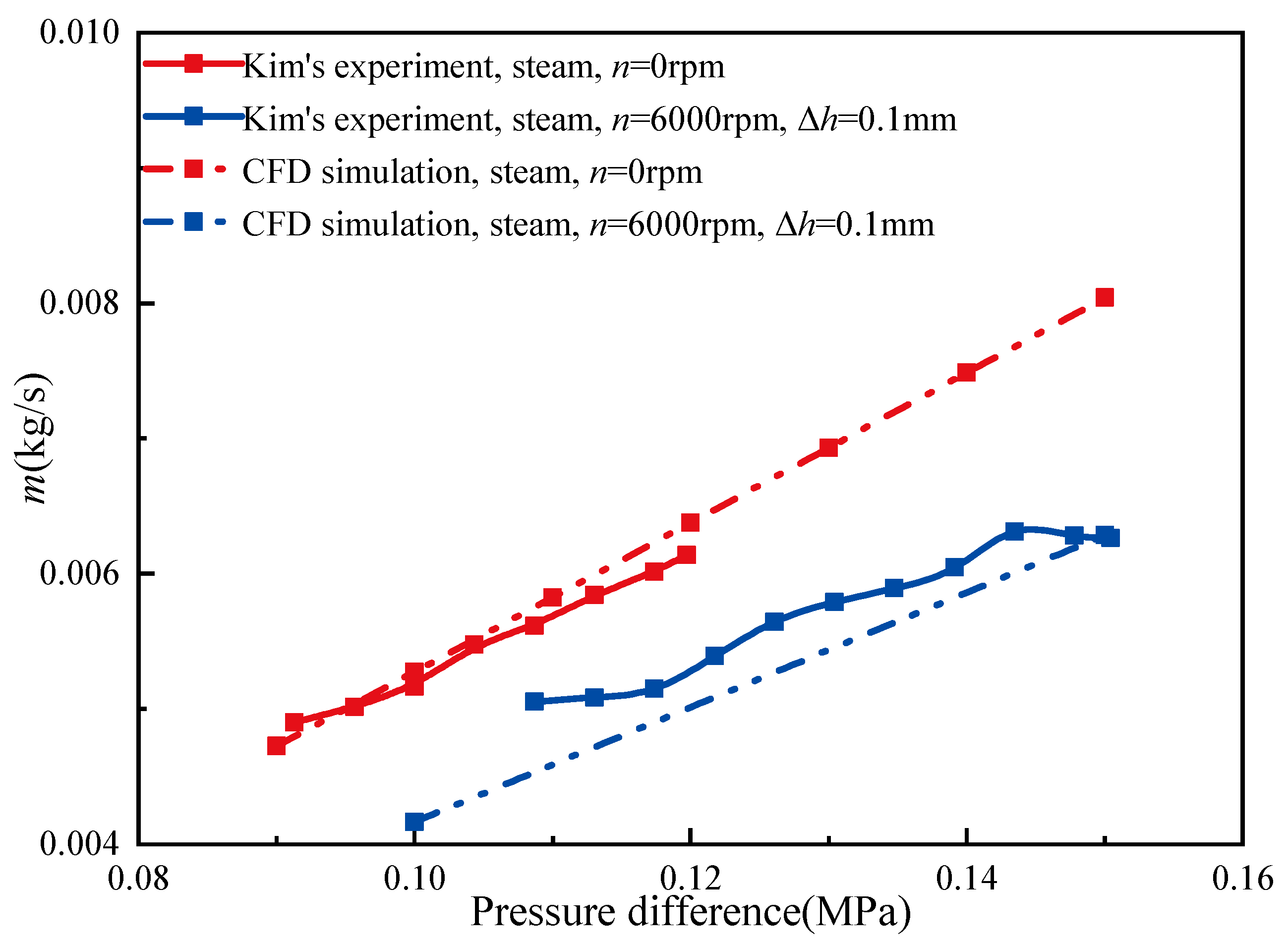
The Hb = 1.78 mm results of the CFD simulation and Kim’s experiment [42] are compared in Figure 10, and all leakage rates increase with an increase in pressure. In the static condition, the simulation results in this paper are in good agreement with the experimental results, and the conclusion is the same as the previous study [15]. This proves the reliability of the porous medium model in predicting the leakage rate of brush seals in this paper. In the dynamic condition, the leakage rate is smaller than the leakage rate of the static condition. When the rotor is running, the friction heat between the bristle’s tip and the rotor results in an increase in temperature with respect to the working fluid. Due to the viscosity and swelling of the working fluid, the leakage rate is reduced. In the dynamic condition, the maximum simulation error is 20%, and it is similar to Li’s study [43]. From Figure 10, the error value difference reduces when the pressure increases. Generally, the difference value of the dynamic condition between the simulation model and the experiment is acceptable. This means that the model of this paper can be applied in the study of the performance of brush seals.
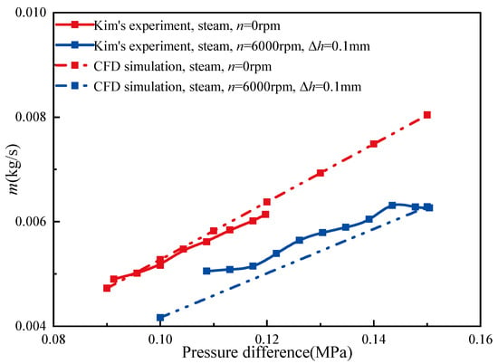
Figure 10.
The results of comparing Kim’s experiment [42] and the CFD simulation.
3.2. The Influence of Rotational Speeds on the Leakage Rate and Heat Transfer
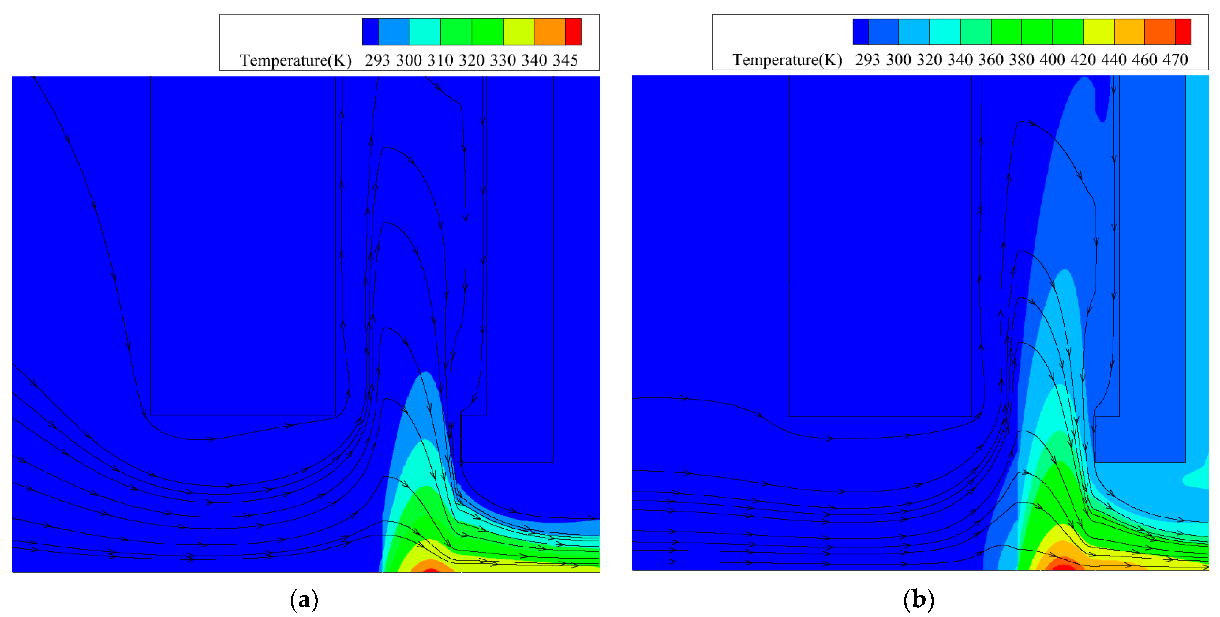
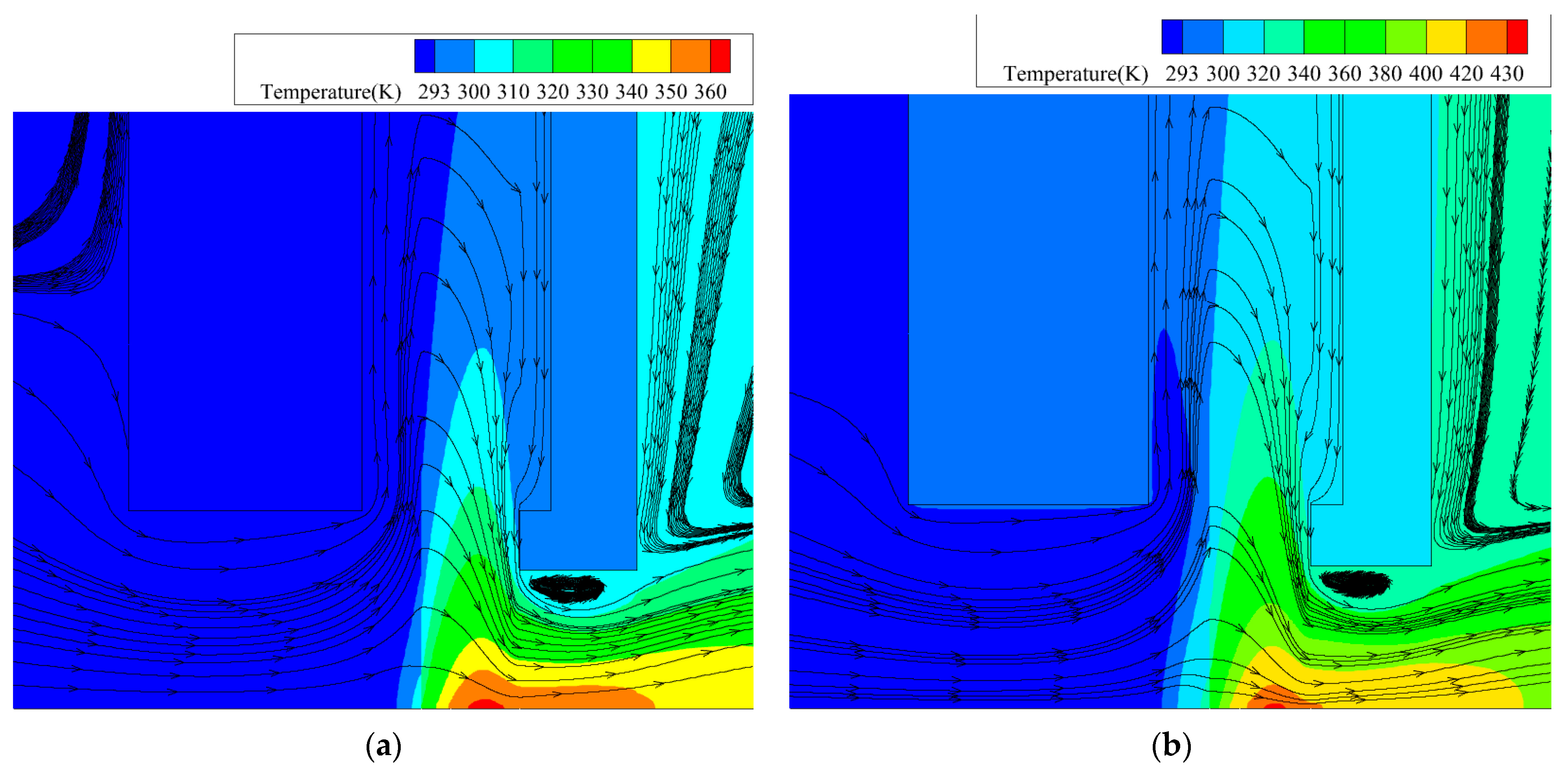
The temperature field and flow line at different rotational speeds are shown in Figure 11. Compared to the model of n = 2000 rpm, the local temperature and the radial temperature are higher at n = 6000 rpm. From the flow line, it was observed that the air cools heat via heat convection.
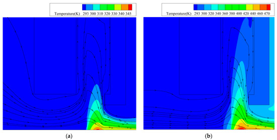
Figure 11.
Temperature field and flow line of the brush seal (Hb = 1.78 mm, Δh = 0.1 mm, and pu = 0.2 MPa): (a) n = 2000 rpm; (b) n = 6000 rpm.
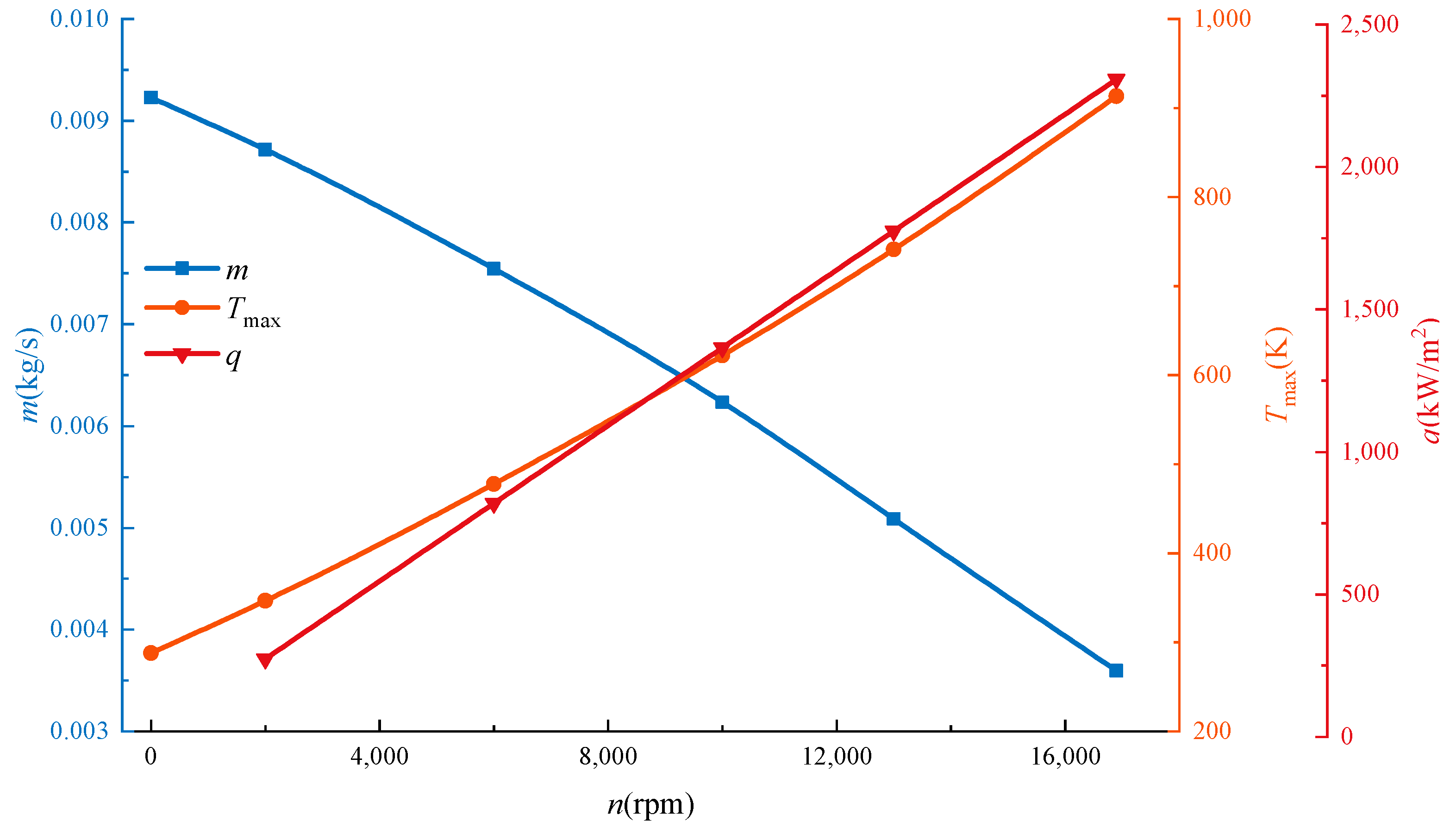
Figure 12 shows the change in q, m, and Tmax at different rotational speeds. q increases linearly, and Tmax increases with an increase in n. Compared to the static condition, Tmax increases more than two times when n is 16,900 rpm. Generally, m decreases with an increase in n. When n is 16,900 rpm, m is 0.0036 kg/s, and it is reduced by 61% in comparison to the static condition. Due to the increase in n, the temperature of the bristle pack increases, leading to an increase in air viscidity and a decrease in m. However, the high rotational speed can cause the destruction of the seal. The bristle material could reach the melting point, leading to the melting of the bristle’s tip.
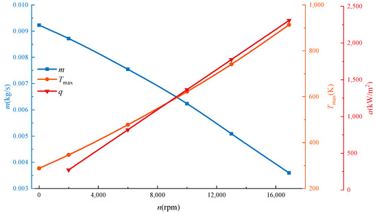
Figure 12.
The friction heat flux q, leakage rate m, and Tmax at different rotational speeds (Hb = 1.78 mm, Δh = 0.1 mm, and pu = 0.2 MPa).
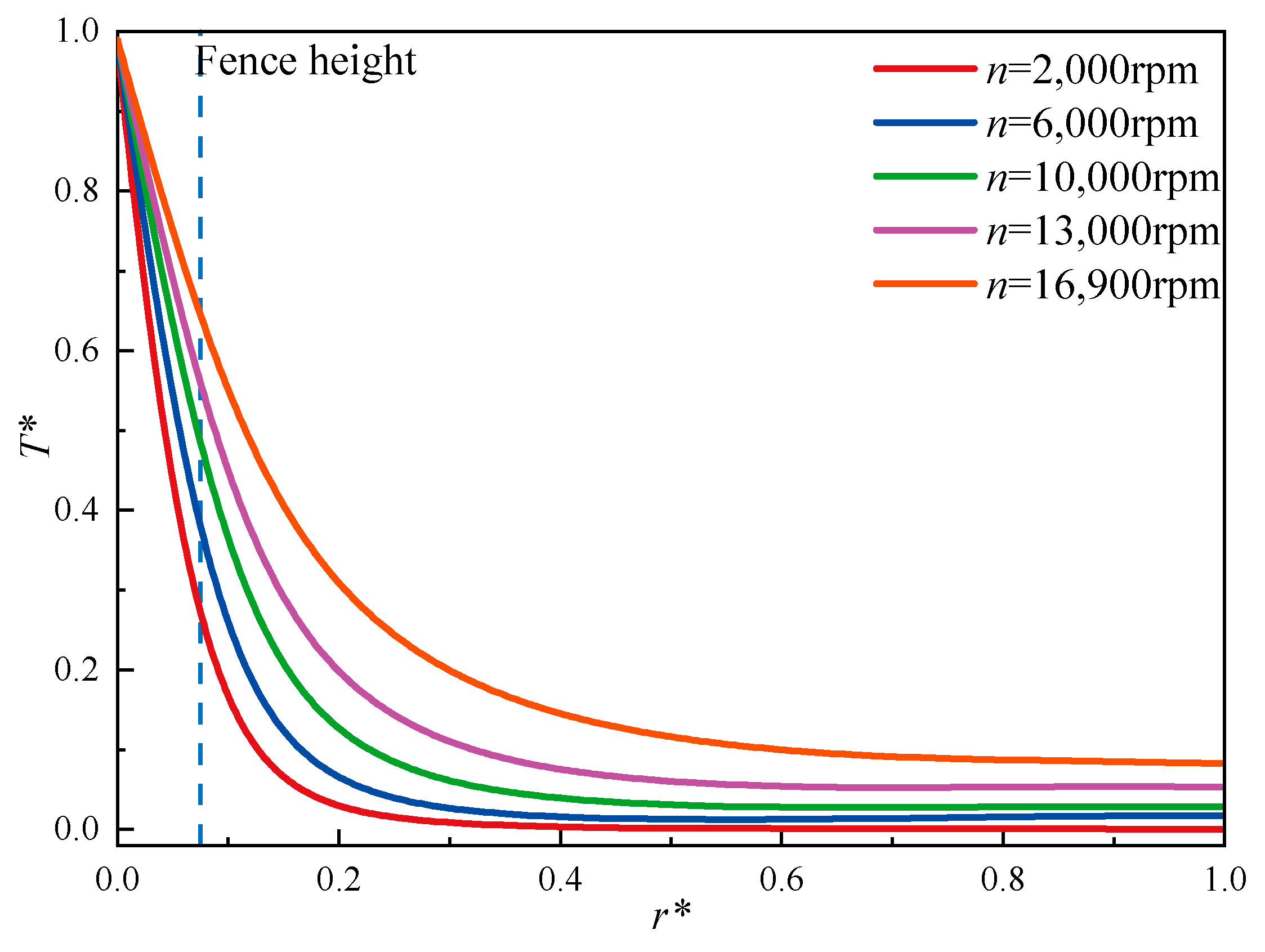
For comparing the variation in the temperature distribution relative to the radial direction, the radial coordinates and temperature are analyzed using non-dimensional parameters. Figure 13 shows the dimensionless temperature T* distribution in the middle section of the bristle pack. It was observed that when the rotational speed increases, the capacity of heat conduction is enhanced in the radial direction. T* is 0.2725 with respect to the fence’s height, and it is 5.28 × 10⁻⁴ with respect to the bristle root at n =2000 rpm. When n is 16,900 rpm, T* is 0.6446 with respect to the fence’s height, and it is 0.0831 with respect to the bristle root; they increase 1.36 times and 156.39 times, respectively. Because of the increase in q, effective thermal conductivity increases significantly in the radial direction. Meanwhile, heat convection is weakened. Therefore, the overall dimensionless temperature increases with an increase in n.
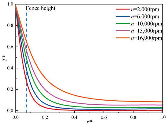
Figure 13.
The radial dimensionless temperature distribution in the middle section of the bristle pack.
3.3. The Influence of Pressure Difference on the Leakage Rate and Heat Transfer
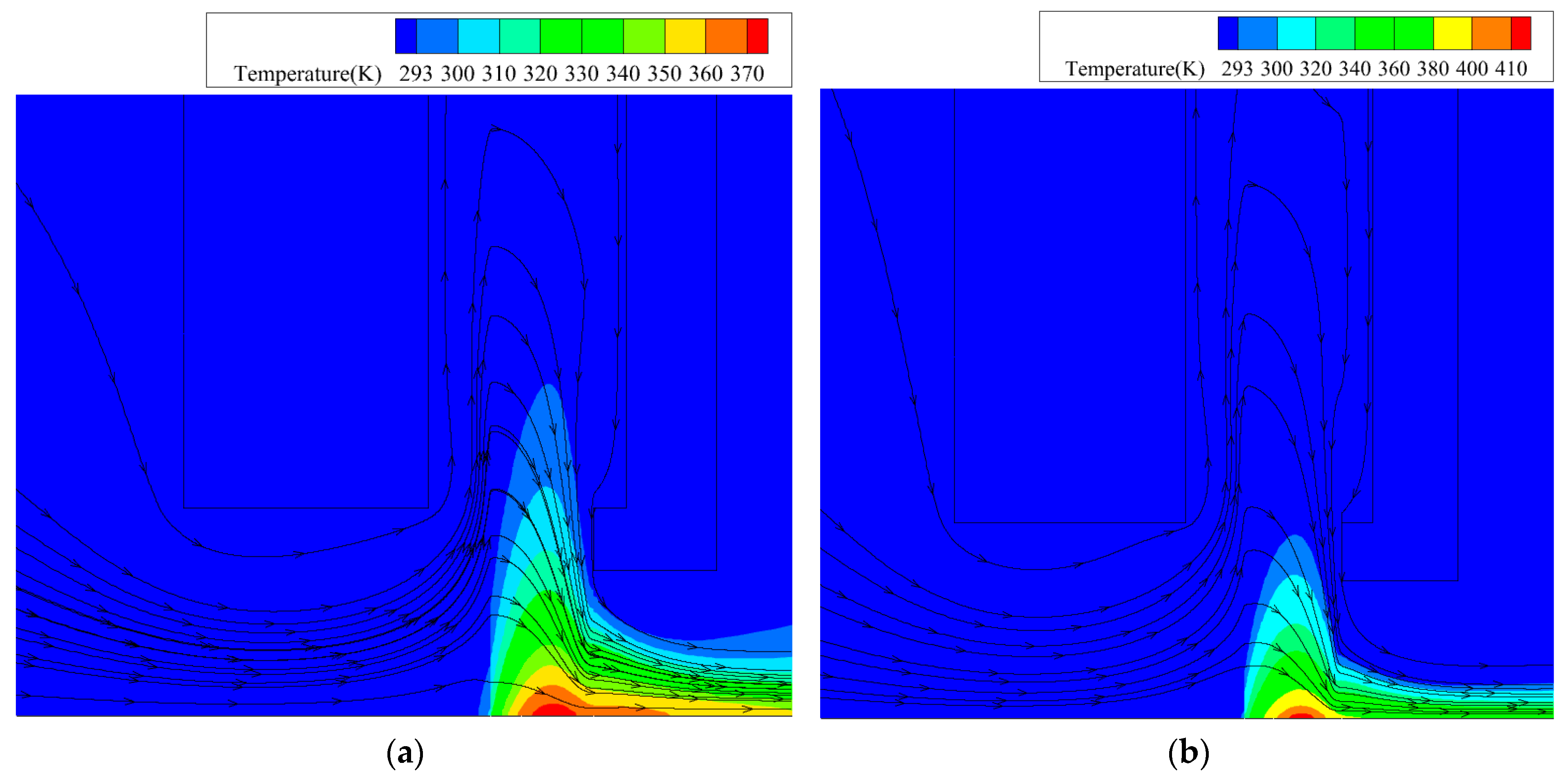
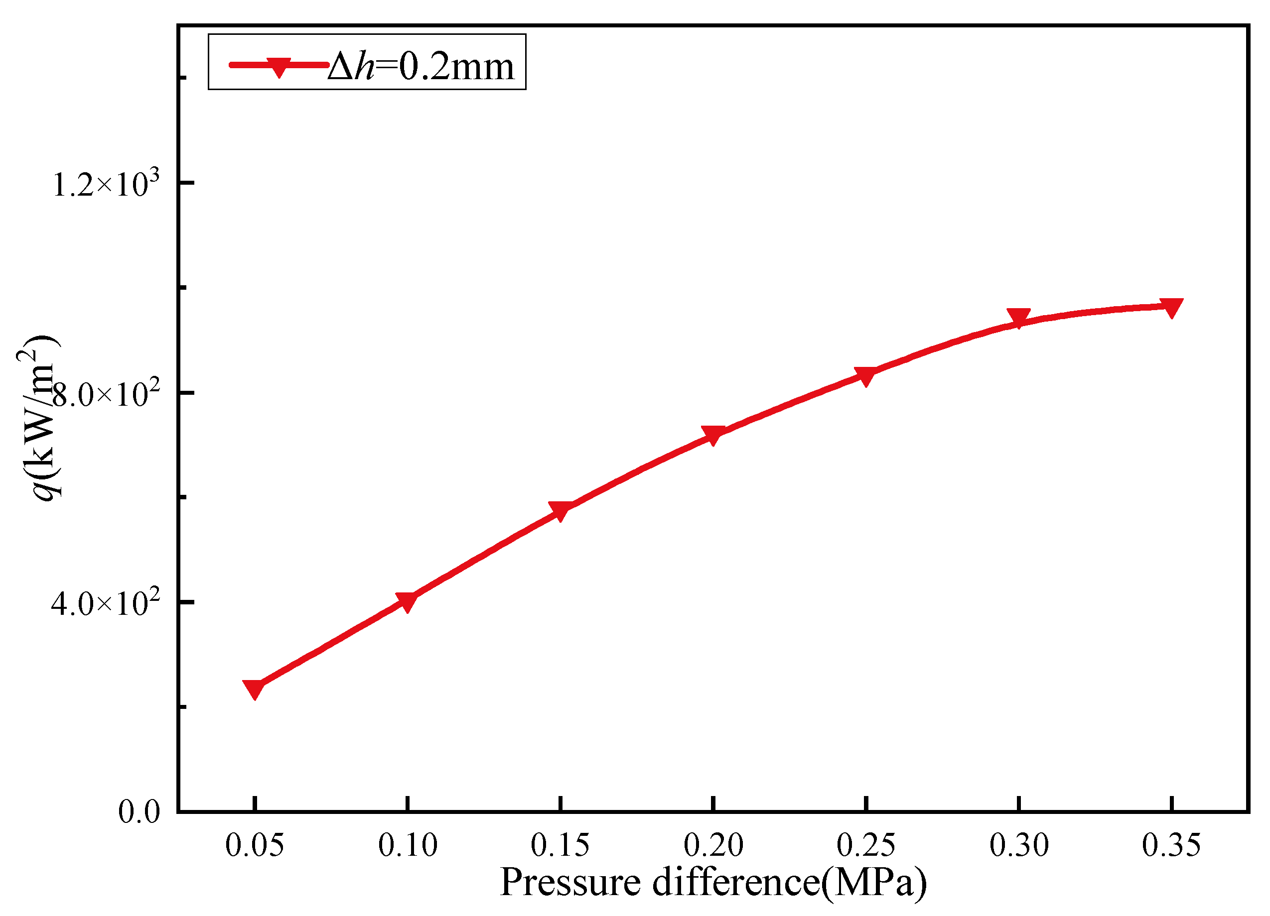
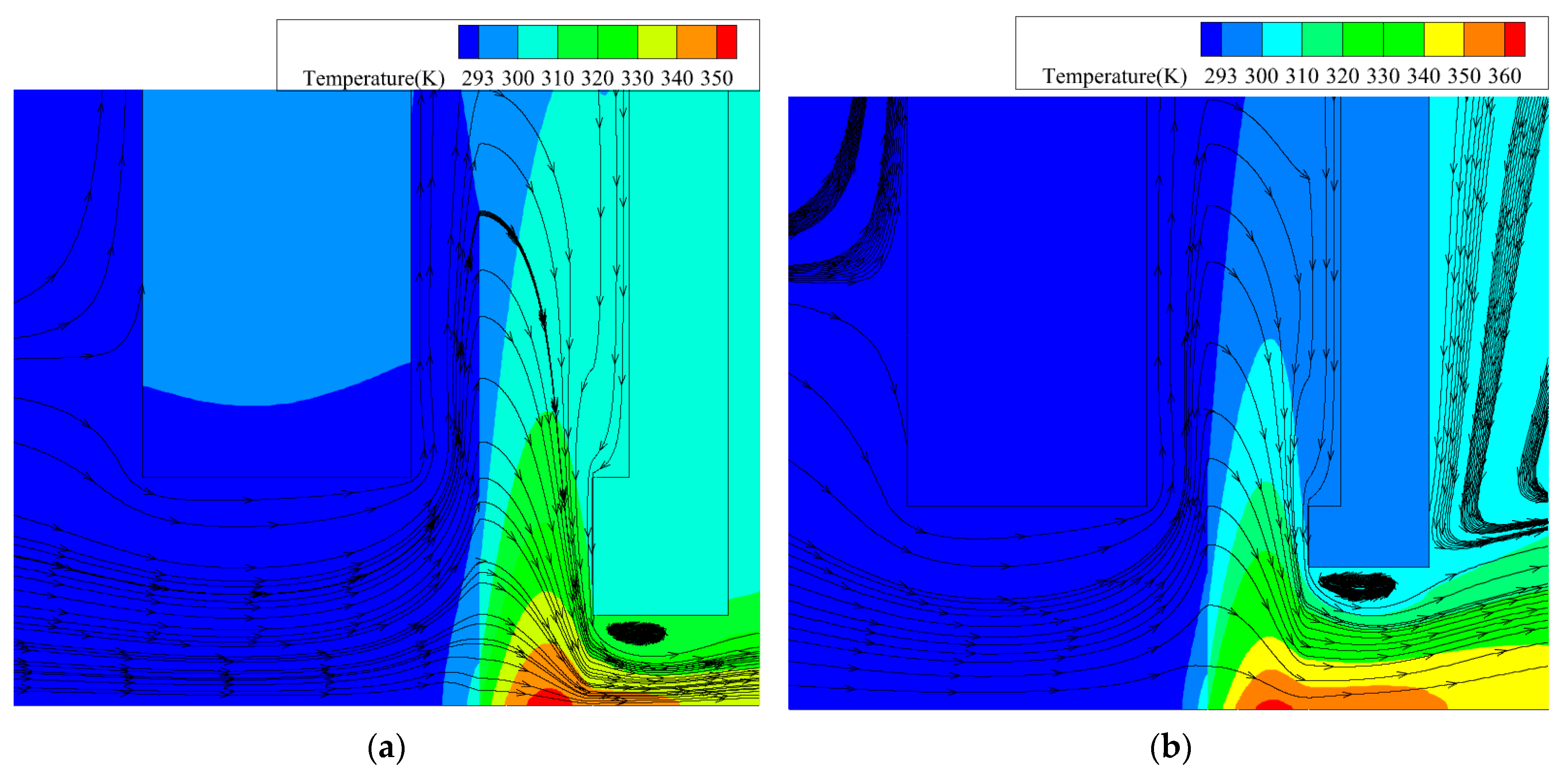
Figure 14 shows the temperature field of pu = 0.2 MPa and pu = 0.4 MPa. When pu is 0.2 MPa, the bristle pack carries out heat exchange with upstream and downstream fluids. Compared with the pu = 0.2 MPa case, the local temperature is higher, but the radial temperature is lower in the pu = 0.4 MPa situation. Figure 15 shows the friction heat flux at different pressure differences. It was observed that heat flux increases with a gradual increase in pressure difference. The air pressure compresses the bristle pack, leading to the heightening of the bristle pack’s stiffness. When pu is 0.45 MPa, the bristle pack’s compression reaches the limit, and the bristle pack’s stiffness no longer increases.
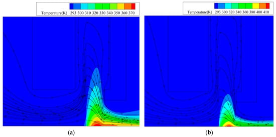
Figure 14.
Temperature field and flow line at different pressure differences (n = 2000 rpm, Δh = 0.2 mm, and Hb = 1.78 mm): (a) pu = 0.2 MPa; (b) pu = 0.4 MPa.
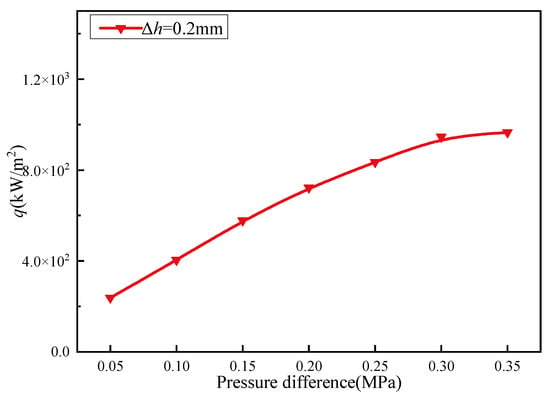
Figure 15.
The friction heat flux q at different pressure differences (n = 2000 rpm, Δh =0.2 mm, and Hb = 1.78 mm).
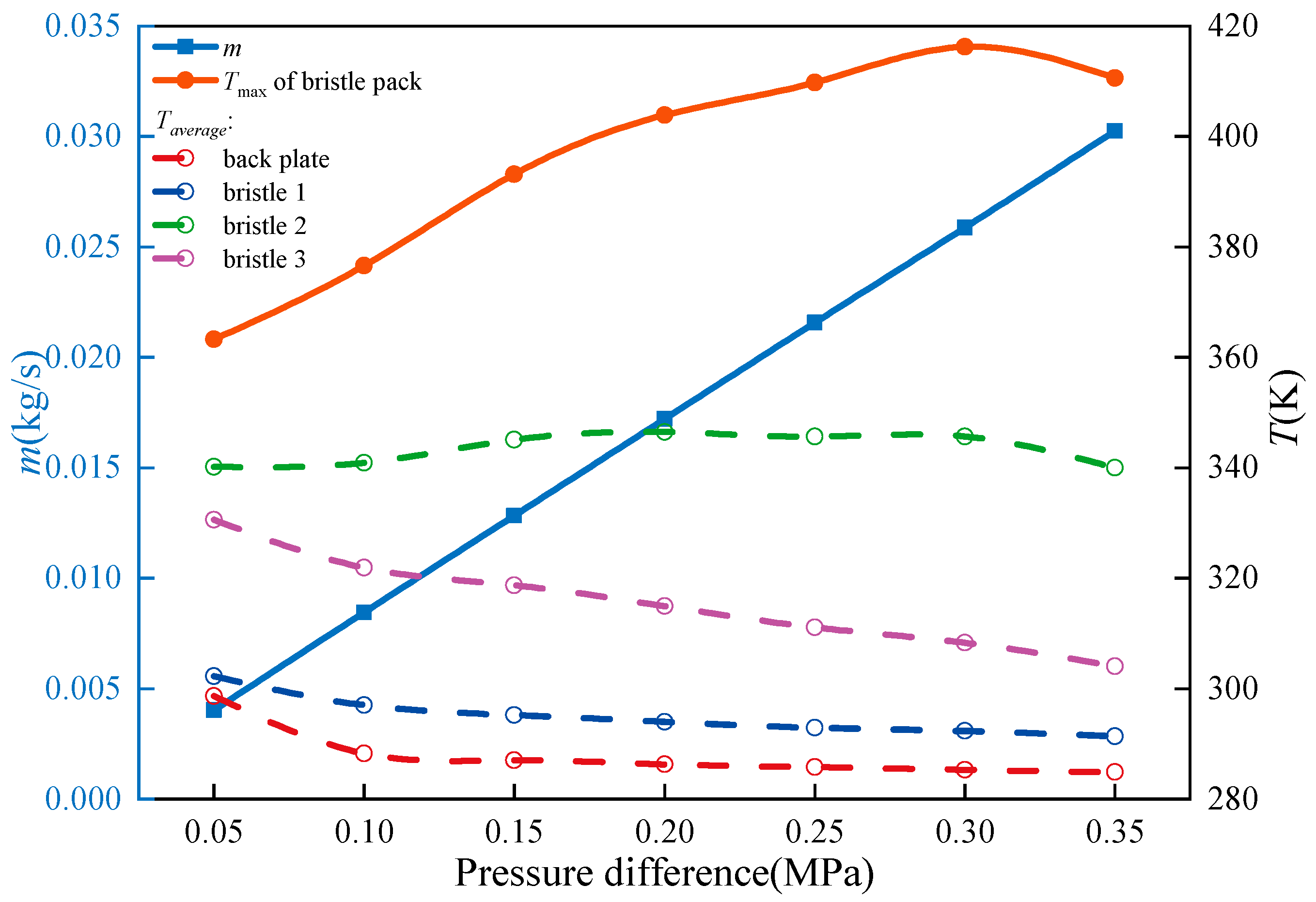
Figure 16 shows the variation in m and the temperature. m increases linearly with an increase in pressure difference. Tmax also increases and reaches the maximum value at pu = 0.4 MPa. When pu is less than 0.4 MPa, the augmentation of m enhances convective heat transfers, but it is sufficient for counteracting the influence of friction heat. Therefore, Tmax increases with an increase in pressure. When pu is greater than 0.4 MPa, the increase rate of q would slow down, and m decreases, leading to a decrease in Tmax. In general, the Taverage of the bristles with respect to the fence’s height and back plate decreases with an increase in pressure. This demonstrates that the pressure difference enhances the heat convection between the bristles and airflow. Airflow can transfer heat from the bristles.
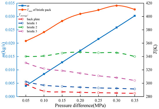
Figure 16.
The leakage rate and the temperature of the brush seal at different pressure differentials (n = 2000 rpm, Δh = 0.2 mm, and Hb = 1.78 mm).
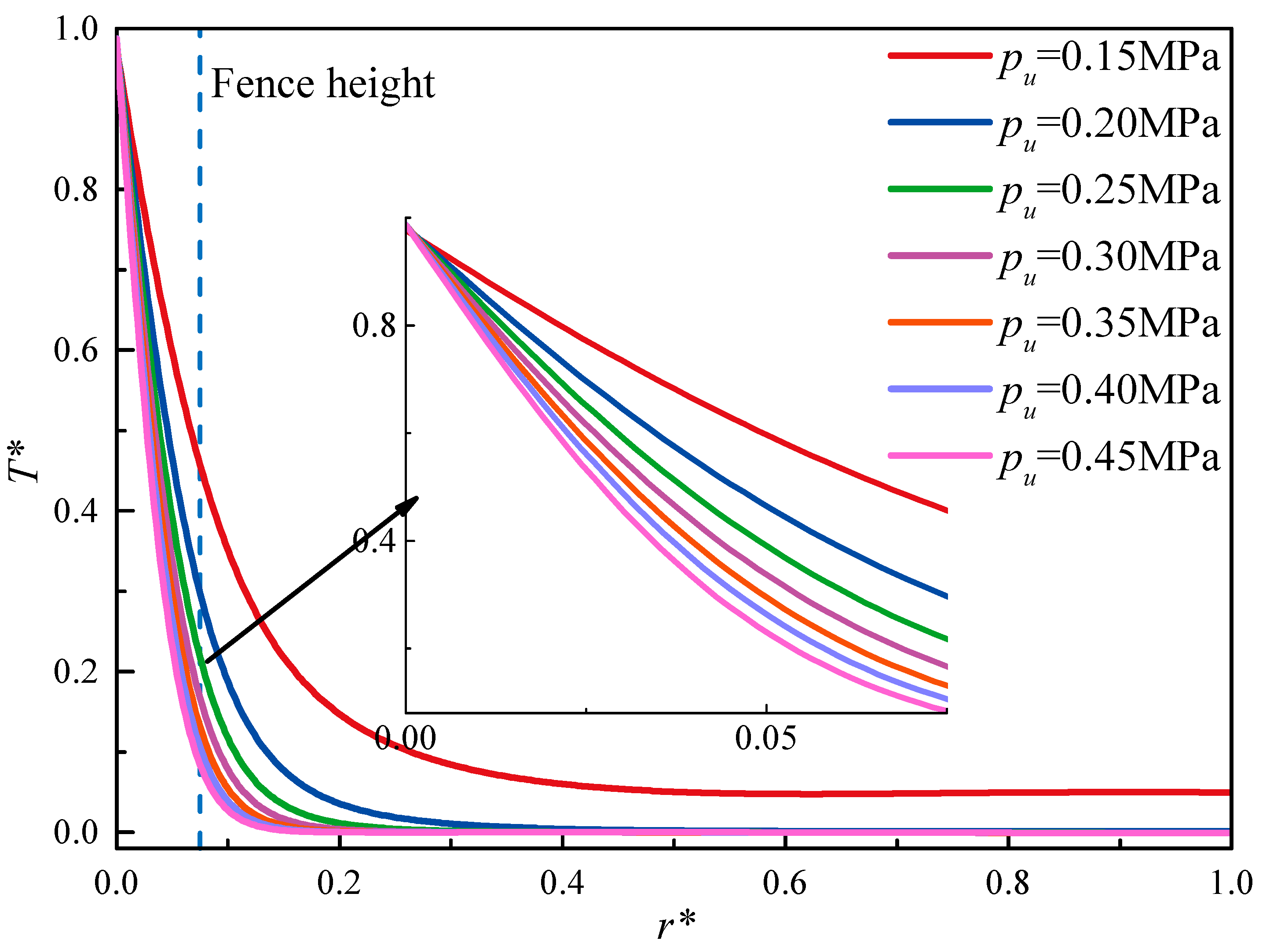
Figure 17 shows the radial temperature distribution curve of the middle part of the bristle pack. It can be observed that the cooling rate of the bristles is enhanced with an increase in pressure in the radial direction. In conclusion, when pressure increases, local temperatures increase, but heat convection is enhanced, restraining heat conduction in the radial direction. T* decreases from 0.977 to 0.457 when r* is pu = 0.15 MPa from the bristle’s tip relative to the fence’s height, and the cooling ratio is 0.532. When pu is 0.45 MPa, T* decreases from 0.987 to 0.084 when r* is obtained from the tip to the fence’s height, and the cooling ratio is 0.915.
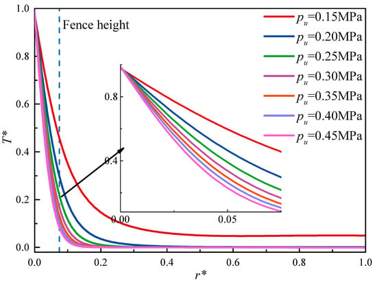
Figure 17.
The radial temperature distribution at different pressure differentials (n = 2000 rpm, Δh = 0.2 mm, and Hb = 1.78 mm).
3.4. The Influence of the Magnitude of Interference on the Leakage Rate and Heat Transfer
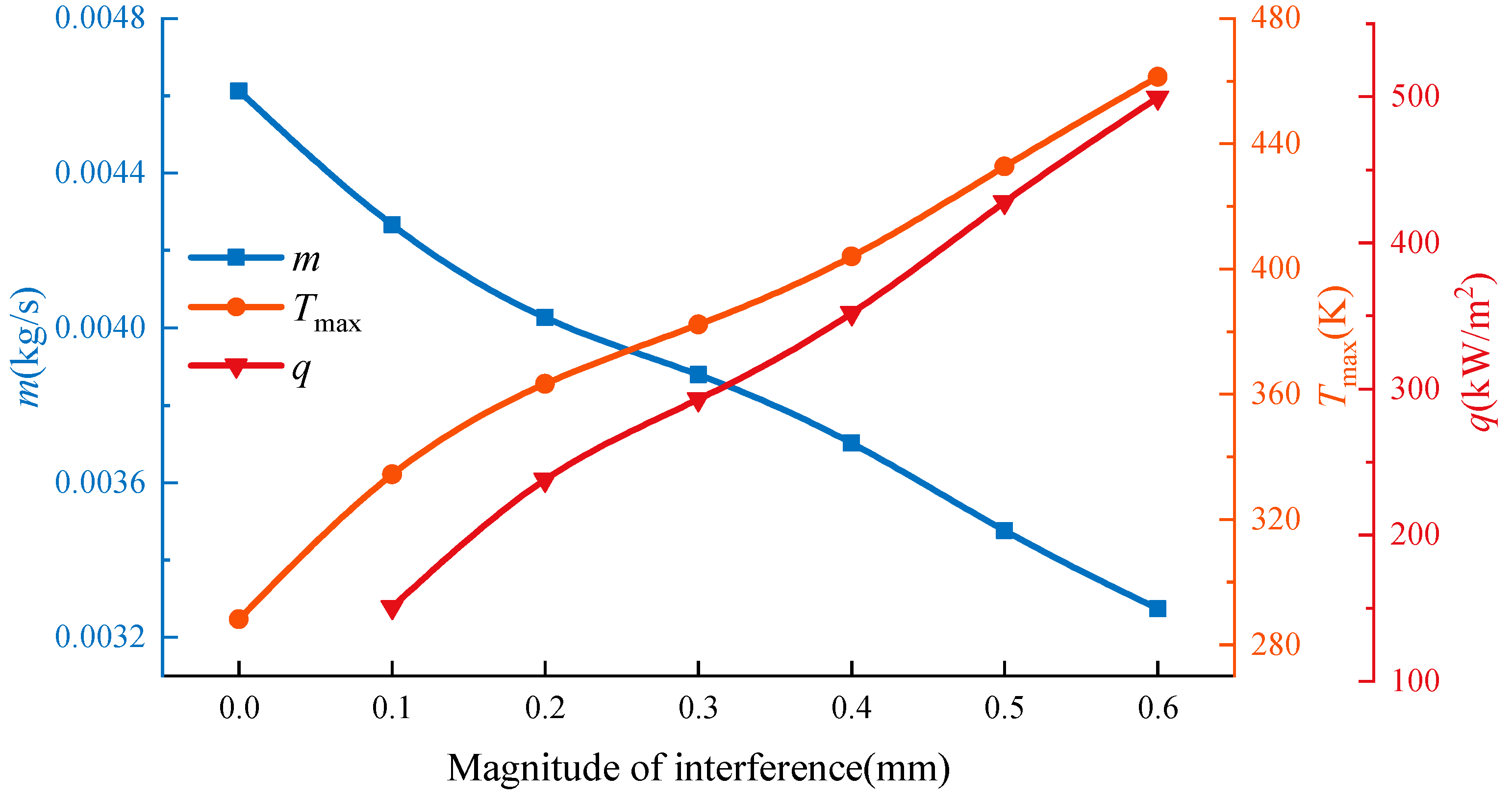
Figure 18 shows the temperature field of the brush seal at different Δh values. Compared with Δh = 0.2 mm, Tmax and the radial temperature are higher at Δh = 0.5 mm. Figure 19 shows q, m, and Tmax at different Δh values. It was observed that due to an increase in q, m decreases, and Tmax increases with an increase in Δh. These results are similar to the numerical results of Zhang [19] and Li [44]. Because of the increase in interference, the seal tip’s force and the temperature of the bristle pack increase. The gas expands, and gas viscosity increases. These reasons cause a decrease in the leakage rate. The variation of the leakage rate is the same as Li’s experiment [7] about the different interference. Tmax increases from 288 K to 461.35 K, and the increasing rate is 60.2% when the static condition transfers to the condition of Δh = 0.6 mm. m reduces from 0.00461 kg/s to 0.00327 kg/s, and the reduction rate is 29.06%.
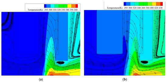
Figure 18.
Temperature field of the brush seal at different magnitudes of interference (n = 2000 rpm, pu = 0.15 MPa, and Hb = 1.78 mm): (a) Δh = 0.2 mm; (b) Δh = 0.5 mm.
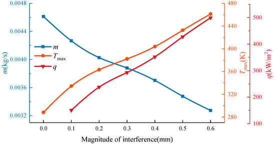
Figure 19.
The friction heat flux, the leakage rate, and the maximum temperature at different magnitudes of interference (n = 2000 rpm, pu = 0.15 MPa, and Hb = 1.78 mm).
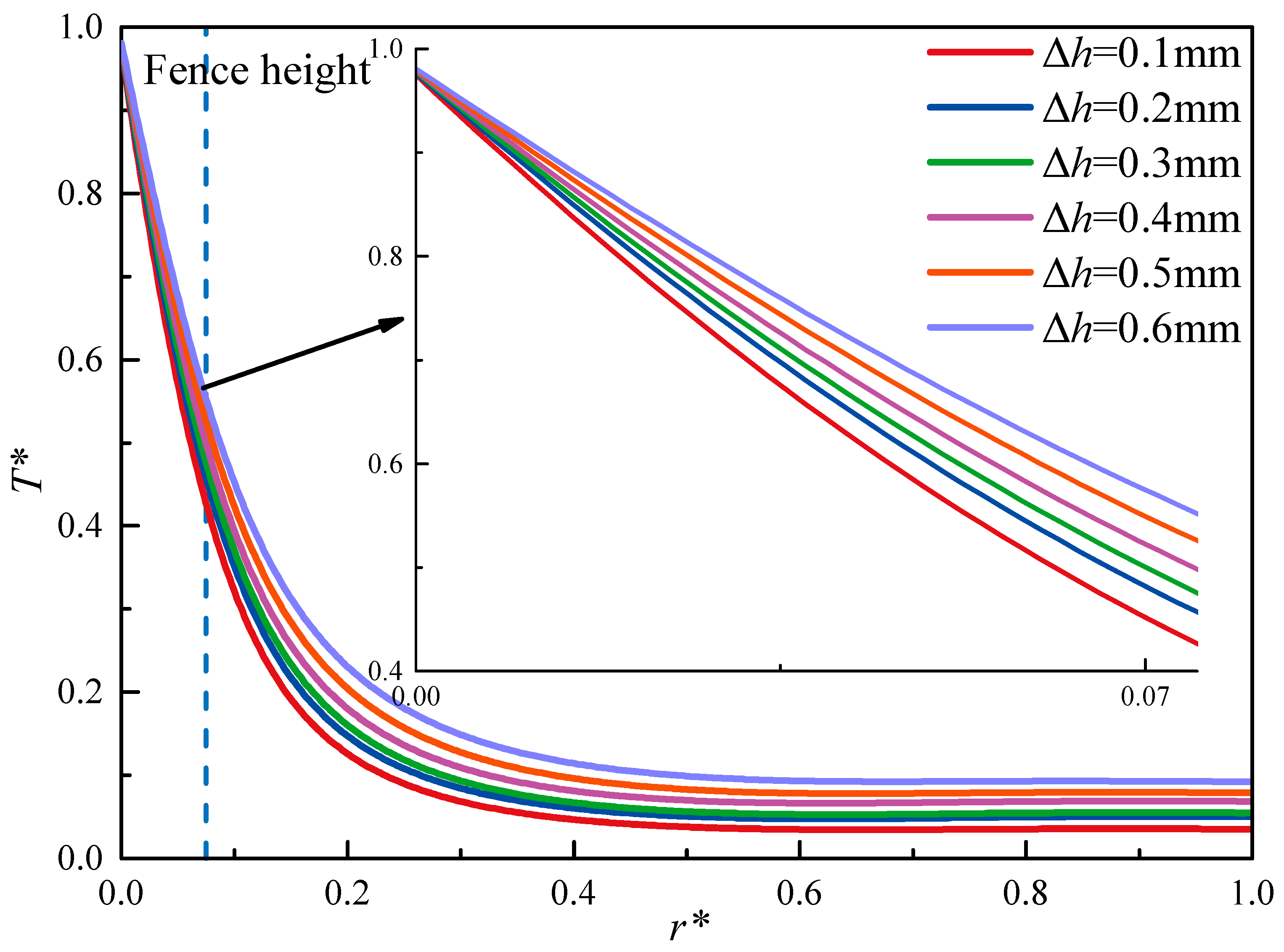
Figure 20 shows the dimensionless temperature, T*, in the radial coordinate at different Δh values. It was observed that a great deal of heat is conducted along the radial direction, and the temperature increases to a finite value. T* increases from 0.427 to 0.552 relative to the fence’s height when the magnitude of interference increases from 0.1 mm to 0.6 mm. In conclusion, the increase in Δh can reduce m, but this aggravates the temperature of the bristle tip. If the rotor speed is excessively fast, the large magnitude of interference not only aggravates the bristle’s abrasion but also causes the melting of the bristle tip. Therefore, the radial displacement of the rotor requires extra attention.
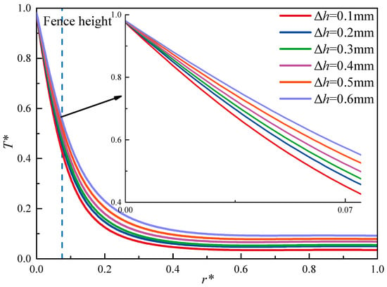
Figure 20.
The radial temperature distribution of the middle part of the bristle pack at different magnitudes of interference (n = 2000 rpm, pu = 0.15 MPa, and Hb = 1.78 mm).
3.5. The Influence of Fence Height on the Leakage Rate and Heat Transfer
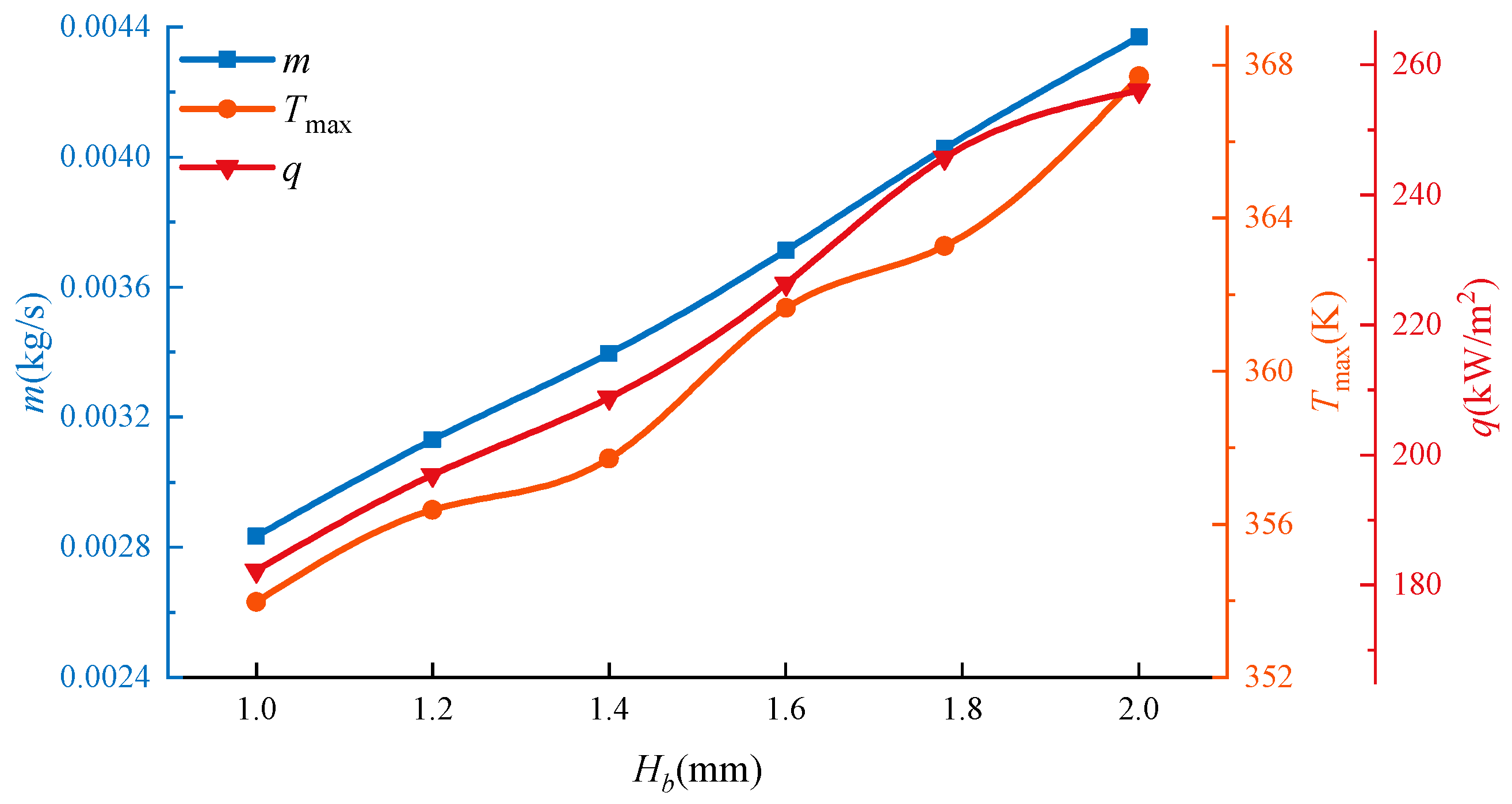
Figure 21 shows the temperature field of the brush seal at different Hb values. Compared with the situation of Hb = 1 mm, Tmax is higher, but the quantity of heat is smaller in the radial direction when Hb = 1.78 mm. Figure 22 shows the change in q, m, and Tmax at different Hb values. Q, Tmax, and m all increase with an increase in Hb. The conclusion is similar to Zhang’s study [45,46], and the reason is that the stiffness of the bristle pack increases with an increase in fence height at low-pressure differences [3]. When Hb increases from 1 mm to 2 mm, m increases from 0.00283 kg/s to 0.00437 kg/s, and the increase percentage is 54.4%. Tmax increases from 353.97 K to 367.71 K, and the increase percentage is 3.88%. The increase in Hb enlarges the flow area, leading to an increase in leakage rate. The expansion of the windward area causes an increase in the bristle pack’s stiffness; thus, the heat flux and temperature increase.
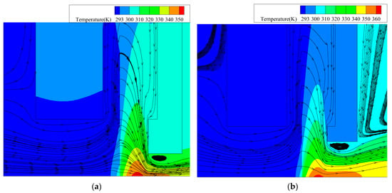
Figure 21.
Temperature field of the brush seal at different fence heights (pu = 0.15 MPa, n = 2000 rpm, and Δh = 0.2 mm): (a) Hb = 1 mm; (b) Hb = 1.78 mm.
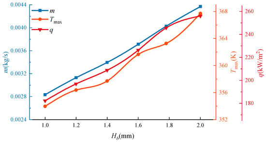
Figure 22.
The friction heat flux, leakage rate, and maximum temperature at different fence heights (pu = 0.15 MPa, n = 2000 rpm, and Δh = 0.2 mm).
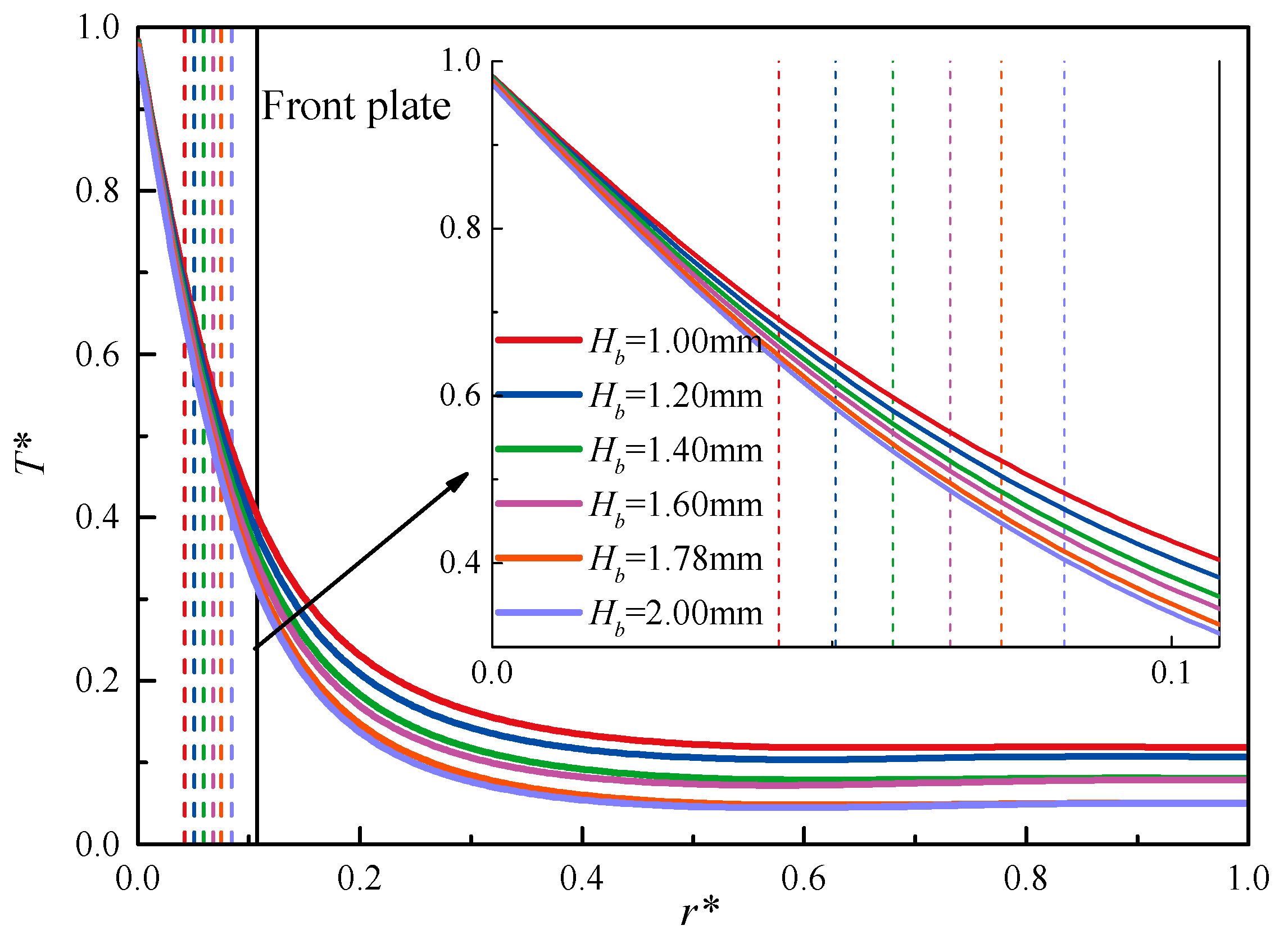
Figure 23 shows the radial dimensionless temperature T* distribution. Two phenomena can be found. Firstly, the temperature rapidly decreases from the tip to the root of the bristles. Next, T* decreases with the increase in fence height. At the position of Hf = 2.54 mm, the temperature of Hb = 2 mm is 1.475 K lower than Hb = 1 mm. Due to the increase in flow area, the increase in the contact area between air and the bristles causes an increase in heat convection. Therefore, the cooling rate increases with an increase in fence height.
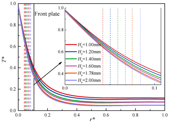
Figure 23.
The radial dimensionless temperature distribution at different fence heights in the middle section of the bristle pack (pu = 0.15 MPa, n = 2000 rpm, and Δh = 0.2 mm).
4. Conclusions
Due to the heat transfer characteristic of the brush seal, a porous medium with an anisotropic heat transfer model was established in this paper. The leakage rate and the temperature of bristles were analyzed by combining the CFD and FEA models. The conclusions are as follows:
- (1)
- The maximum temperature increases at the contact region between the bristle’s tip and the rotor surface. The temperature rapidly decreases in the radial direction relative to the fence’s height. From the temperature field, the isothermal line is approximately a parabolic arc.
- (2)
- The pressure difference, rotational speed, and magnitude of interference all cause a temperature increase relative to the bristle’s tip. The pressure difference can enhance the convective heat transfer effect of airflow. Therefore, the cooling rate increases in the radial direction. The excessive rotational speed and large interference can aggravate the melting of bristles. When the rotational speed and the magnitude of interference increase, heat spreads in the radial direction, and the bulk temperature of bristles exhibits an obvious increase.
- (3)
- When the pressure increases, the average temperature of the bristles in different positions decreases in varying degrees. This also demonstrates that the increase in pressure can enhance the convective heat transfer effect of airflow.
- (4)
- In the low-pressure scenario, the friction heat flux increases with an increase in fence height. This means that the global stiffness of the bristle pack increases. Therefore, the leakage rate and maximum temperature increase with an increase in fence height. However, higher fence heights can enhance the convective heat transfer effect, and the radial temperature of the bristles is reduced.
Author Contributions
Conceptualization, M.L. and X.S.; methodology, X.S.; software, X.S.; validation, M.L., X.S. and J.S.; formal analysis, X.S.; investigation, X.S.; resources, X.S.; data curation, X.S.; writing—original draft preparation, X.S.; writing—review and editing, M.L., J.S., J.W. and K.W.; visualization, X.S.; supervision, M.L.; project administration, M.L.; funding acquisition, M.L. All authors have read and agreed to the published version of the manuscript.
Funding
This research was funded by the National Natural Science Foundation of China, grant number No. 51765024. The APC was funded by No. 51765024.
Data Availability Statement
Not applicable.
Acknowledgments
The authors thank the editors and reviewers for their comments and help. All authors agree to submit this study for publication.
Conflicts of Interest
The authors declare no conflict of interest. The funders had no role in the design of the study; in the collection, analyses, or interpretation of data; in the writing of the manuscript; or in the decision to publish the results.
References
- Chupp, R.E.; Hendricks, R.C.; Lattime, S.B.; Steinetz, B.M. Sealing in turbomachinery. J. Propuls. Power 2006, 22, 313–349. [Google Scholar] [CrossRef]
- Chupp, R.; Ghasripoor, F.; Turnquist, N.A.; Demiroglu, M.; Aksit, M.F. Advanced seals for industrial turbine applications: Dynamic seal development. J. Propuls. Power 2002, 18, 1260–1266. [Google Scholar] [CrossRef]
- Hildebrandt, M.; Schwarz, H.; Schwitzke, C.; Bauer, H.-J.; Friedrichs, J. Effects of the back plate inner diameter on the frictional heat input and general performance of brush seals. Aerospace 2018, 5, 58. [Google Scholar] [CrossRef]
- Bowen, J.P.; Jenkins, M.R.; Bowsher, A.A.; Crudgington, P.F.; Sangan, C.M.; Scobie, J.A. The inter-bristle pressure field in a large-scale brush seal. J. Eng. Gas Turbines Power 2022, 144, 111022. [Google Scholar] [CrossRef]
- Bowen, J.P.; Bird, J.J.; Cross, H.; Jenkins, M.R.; Bowsher, A.A.; Crudgington, P.F.; Sangan, C.M.; Scobie, J.A. Fluid dynamic behaviour of conventional and pressure relieving brush seals. In Proceedings of the ASME Turbo Expo 2023 Turbomachinery Technical Conference and Exposition, Boston, MA, USA, 26–30 June 2023; American Society of Mechanical Engineers: Boston, MA, USA, 2023; pp. 1–14. [Google Scholar]
- Raben, M.; Friedrichs, J.; Flegler, J. Brush seal frictional heat generation—Test rig design and validation under steam environment. J. Eng. Gas Turbines Power 2017, 139, 032502. [Google Scholar] [CrossRef]
- Li, P.; Hu, Y.; Ji, H.; Cui, X.; Liu, L.; Li, S. Experimental investigation on leakage characteristics of low-hysteresis brush seals. J. Eng. Gas Turbines Power 2022, 144, 071010. [Google Scholar] [CrossRef]
- Duran, E.T. Methodology for counter torque, power loss, and frictional heat for brush seals under eccentric transients. Tribol. Trans. 2023, 66, 249–267. [Google Scholar] [CrossRef]
- Dowler, C.A.; Chupp, R.E.; Holle, G.E. Simple effective thickness model for circular brush seals. In Proceedings of the AIAA/ASME/SAE/ASEE 28th Joint Propulsion Conference and Exhibit, Nashville, TN, USA, 6–8 July.
- Song, X.; Liu, M.; Hu, X.; Wang, X.; Liao, T.; Sun, J. Numerical analysis of flow across brush elements based on a 2-D staggered tube banks model. Aerospace 2021, 8, 19. [Google Scholar] [CrossRef]
- Zhao, H.; Li, Y.; Sun, D.; Li, Y.; Wen, S.; Sun, J. Inter-stage pressure drop of multi-stage brush seal with differentiated structure. J. Eng. Gas Turbines Power 2023, 145, 071001. [Google Scholar] [CrossRef]
- Bayley, F.J.; Long, C.A. A combined experimental and theoretical study of flow and pressure distributions in a brush seal. J. Eng. Gas Turbines Power 1993, 115, 404–410. [Google Scholar] [CrossRef]
- Chew, J.W.; Lapworth, B.L.; Millener, P.J. Mathematical modeling of brush seals. Int. J. Heat Fluid Flow 1995, 16, 493–500. [Google Scholar] [CrossRef]
- Qiu, B.; Li, J.; Feng, Z. Investigation of conjugate heat transfer in brush seals using porous media approach under local thermal non-equilibrium conditions. In Proceedings of the ASME Turbo Expo(2015), Montreal, QC, Canada, 15–19 June 2015; American Society of Mechanical Engineers: New York, NY, USA, 2015. [Google Scholar]
- Song, X.; Liu, M.; Yang, J. Numerical analysis of leakage performance of brush seal based on a 2-d tube bank model and porous medium model considering the effect of compressible gas. Int. J. Fluid Mach. Syst. 2022, 15, 329–343. [Google Scholar] [CrossRef]
- Tian, C.; Kong, X.; Wang, X.; Li, J.; Zhai, X. New technologies approach to design impulse high pressure turbine stages. In Proceedings of the International Conference on Power Engineering (ICOPE), Yokohama, Japan, 30 November–4 December 2015. [Google Scholar]
- Dogu, Y.; Aksit, M.F. Brush seal temperature distribution analysis. J. Eng. Gas Turbines Power 2006, 128, 599–609. [Google Scholar] [CrossRef]
- Zhang, Y.Q.; Wang, Y.; Yan, X.; Li, J. Investigations on the leakage and heat transfer characteristics of brush seal part 2: Heat transfer characteristics. J. Eng. Thermophys. 2018, 39, 970–976. [Google Scholar]
- Zhang, J.; Liu, M.; Peng, N. Study of heat transfer and leakage characteristics of brush seals based on local temperature non-equilibrium model. Machines 2022, 10, 823. [Google Scholar] [CrossRef]
- Hildebrandt, M.; Schwitzke, C.; Bauer, H.-J. Analysis of heat flux distribution during brush seal rubbing using CFD with porous media approach. Energies 2021, 14, 1888. [Google Scholar] [CrossRef]
- Haruki, N.; Horibe, A.; Nakashima, K. Anisotropic effective thermal conductivity measurement of various kinds of metal fiber materials. Int. J. Thermophys. 2013, 34, 2385–2399. [Google Scholar] [CrossRef]
- Xia, Q.; Gillespie, D.R.H.H.; Owen, A.K.; Franceschini, G. Quasi-static thermal modeling of multiscale sliding contact for unlubricated brush seal materials. J. Eng. Gas Turbines Power 2019, 141, 071016. [Google Scholar] [CrossRef]
- Yan, X.; Wang, W.; Liu, X.; Xu, J.; Wei, D.; Liu, K. A multi-contact model to study the dynamic stick-slip and creep in mechanical frictional pair. J. Adv. Mech. Des. Syst. Manuf. 2020, 14, JAMDSM0064. [Google Scholar] [CrossRef]
- Wang, Q.; Hu, Y.; Ji, H. Leakage, heat transfer and thermal deformation analysis method for contacting finger seals based on coupled porous media and real structure models. Proc. Inst. Mech. Eng. Part C J. Mech. Eng. Sci. 2020, 234, 2077–2093. [Google Scholar] [CrossRef]
- Thakare, M.R.; Mason, J.F.; Owen, A.K.; Gillespie, D.R.H.; Wilkinson, A.J.; Franceschini, G. Effect of sliding speed and counterface properties on the tribo-oxidation of brush seal material under dry sliding conditions. Tribol. Int. 2016, 96, 373–381. [Google Scholar] [CrossRef]
- Cui, C.; Tian, P.; Tian, Y. Experimental and finite element analysis of frictional heat distribution during sliding friction. Lubr. Eng. 2017, 42, 23–27. [Google Scholar]
- Al-Sumaily, G.F.; Al Ezzi, A.; Dhahad, H.A.; Thompson, M.C.; Yusaf, T. Legitimacy of the local thermal equilibrium hypothesis in porous media: A comprehensive review. Energies 2021, 14, 8114. [Google Scholar] [CrossRef]
- Shen, H.; Yang, L.; Meng, G. Modeling and simulation of the discharge process of isothermal chamber to determine the isothermal characteristic. J. Therm. Sci. Technol. 2022, 17, 21-00353. [Google Scholar] [CrossRef]
- Shen, H.; Yang, L. Improvement of isothermal characteristic of isothermal chamber by filling with graded copper foam. J. Therm. Sci. Technol. 2023, 18, 22-00397. [Google Scholar] [CrossRef]
- Jagjiwanram, S.R. Effective thermal conductivity of highly porous two-phase systems. Appl. Therm. Eng. 2004, 24, 2727–2735. [Google Scholar] [CrossRef]
- Gail, A.; Beichl, S. MTU brush seal—Main features of an alternative design. In Proceedings of the 36th AIAA/ASME/SAE/ASEE Joint Propulsion Conference and Exhibit; American Institute of Aeronautics and Astronautics, Reston, VA, USA, 24–28 July 2000. [Google Scholar]
- Schur, F.; Friedrichs, J.; Flegler, J.; Georgakis, C.; Polklas, T. Pressure distributions below brush seals at varying operating conditions. In Proceedings of the ASME Turbo Expo (2018), Oslo, Norway, 11–15 June 2018; American Society of Mechanical Engineers: New York, NY, USA, 2018. [Google Scholar]
- Zhang, Y.; Yin, M.; Zeng, Q.; Wang, R.; Zhao, T. Theoretical and experimental studies on the optimization of finger seal. J. Adv. Mech. Des. Syst. Manuf. 2020, 14, JAMDSM0107. [Google Scholar] [CrossRef]
- Kang, Y.; Liu, M.; Hu, X.; Kao-Walter, S.; Zhang, B. Theoretical and numerical investigation into brush seal hysteresis without pressure differential. Adv. Compos. Lett. 2019, 28, 096369351988538. [Google Scholar] [CrossRef]
- Feng, Y.; Zhao, H.; Sun, D.; Mu, W.; Zhang, G.; Li, H. Numerical and experimental research on influence of brush bristle wear on leakage and flow characteristics of brush seal. J. Aerosp. Power 2022, 37, 1234–1247. [Google Scholar] [CrossRef]
- Demiroglu, M. An Investigation of Tip Force and Heat Generationcharacteristics of Brush Seals; Rensselaer Polytechnic Institute: Troy, NY, USA, 2004. [Google Scholar]
- Haynes Stellite Company. HAYNES ALLOY No. 25. Alloy Digest 1961, 10, Co-5. [Google Scholar] [CrossRef]
- Zhang, Y.; Li, J.; Yan, X.; Li, Z. Experimental and numerical investigations on leakage flow characteristics of two kinds of brush seals. In Proceedings of the ASME Turbo Expo (2018), Oslo, Norway, 11–15 June 2018; American Society of Mechanical Engineers: New York, NY, USA, 2018; pp. 1–11. [Google Scholar]
- Bondar, V.S.; Rodin, E.V. Numercial simulation of brush seal tests. Pnrpu Mech. Bull. 2022, 1, 14–22. (In Russian) [Google Scholar] [CrossRef] [PubMed]
- Ha, Y.; Ha, T.; Byun, J.; Lee, Y. Leakage effects due to bristle deflection and wear in hybrid brush seal of high-pressure steam turbine. Tribol. Int. 2020, 150, 106325. [Google Scholar] [CrossRef]
- Ha, Y.; Ha, T.; Byun, J.; Lee, Y. Estimation of the rotordynamic characteristics of a single brush seal using least-squares and instrumental variable methods under super-heated steam environment. Adv. Mech. Eng. 2020, 12, 1687814020913676. [Google Scholar] [CrossRef]
- Kim, T.-G. An Experimental Study on Leakage Characteristics of the Brush Seal for Steam Turbine. Master’s Thesis, Hanyang University, Seoul, Republic of Korea, 2016. [Google Scholar]
- Li, H.; Sun, D.; Zhao, H.; Zhang, G.; Feng, Y. Numerical method of flow and heat transfer characteristics of brush seals. J. Aerosp. Power 2021, 36, 1826–1838. [Google Scholar] [CrossRef]
- Li, L.K.; Wang, Z.L.; Song, F.; Wang, W.; Chen, C.H. Numerical investigation of temperature field in brush seals. J. Aerosp. Power 2010, 25, 1018–1024. [Google Scholar]
- Zhang, Y.Q.; Yan, J.C.; Li, J. Numerical investigations on influence factors of leakage flow and heat transfer characteristics of brush seal. J. Propuls. Technol. 2018, 39, 116–124. [Google Scholar] [CrossRef]
- Zhang, Y.Q.; Li, J.; Xie, Z.Y.; Deng, G.Y. Numerical investigations on leakage flow and frictional heat transfer characteristics of labyrinth-brush seal. J. Propuls. Technol. 2022, 43, 94–104. [Google Scholar] [CrossRef]
Disclaimer/Publisher’s Note: The statements, opinions and data contained in all publications are solely those of the individual author(s) and contributor(s) and not of MDPI and/or the editor(s). MDPI and/or the editor(s) disclaim responsibility for any injury to people or property resulting from any ideas, methods, instructions or products referred to in the content. |
© 2023 by the authors. Licensee MDPI, Basel, Switzerland. This article is an open access article distributed under the terms and conditions of the Creative Commons Attribution (CC BY) license (https://creativecommons.org/licenses/by/4.0/).

