Article

A Study on the Lateral Load Capacity of a Novel Hybrid Monopile via a Centrifuge Model Test

1
Department of Geotechnical Engineering Research, Korea Institute of Civil Engineering and Building Technology, Goyang 10223, Republic of Korea
2
Department of Structural Engineering Research, Korea Institute of Civil Engineering and Building Technology, Goyang 10223, Republic of Korea
3
Section of Geohazards and Dynamics, Norwegian Geotechnical Institute, P.O. Box 3930 Oslo, Norway
4
Department of Civil Engineering, Kangwon National University, Chuncheon 24341, Republic of Korea
*
Author to whom correspondence should be addressed.
Energies 2023, 16(21), 7234; https://doi.org/10.3390/en16217234
Submission received: 10 August 2023 / Revised: 2 October 2023 / Accepted: 20 October 2023 / Published: 24 October 2023
(This article belongs to the Special Issue Novel Design, Modelling and Analysis of Offshore Wind Turbines)

Abstract

:
Large-diameter monopiles that can safely support the lateral loads caused by wind and waves have been widely used for the foundations of offshore wind turbines. However, when the penetration depth is insufficient as a result of the presence of thick soft ground or it is difficult to penetrate rock, the lateral load capacity of the monopiles may be insufficient, leading to structural instability of the wind turbine system. To address this problem, hybrid monopiles have been proposed, which include appendages such as suction buckets attached around the monopiles installed on the seabed. Such suction buckets are arranged in the form of a tripod at 120° intervals with respect to the center of the monopile. These increase the bending resistance of the monopile by sharing the lateral load applied to it. Although the proposed monopiles were presented as conceptual foundation types, their actual support mechanisms and bearing capacity improvement effects must be verified experimentally. In this study, a centrifuge model test was conducted to identify the support mechanism of hybrid monopiles and the degree of improvement in their bearing capacity compared to the existing large-diameter monopiles. The experiment results showed that an appendage composed of suction buckets dispersed the load acting on the monopile, thereby significantly increasing its bearing capacity.

1. Introduction

Since the 2015 Paris climate agreement was signed by more than 190 countries around the world, efforts have been made in many countries to limit greenhouse gas emissions and implement carbon neutrality. The energy sector is one of the most important sectors to realize carbon neutrality, and it is becoming increasingly more important to minimize the environmental damage caused by the use of fossil fuels and produce sustainable energy. In particular, offshore wind power is one of the most popular renewable energy sources. Numerous offshore wind farms had been constructed and were in operation worldwide, and new wind farms are under construction [1]. The size of offshore wind turbines has gradually increased to improve the wind energy productivity, and it is necessary to develop a foundation system that can stably support the increasing environmental load on the wind power system.
Various foundation structures have been proposed to stably support offshore wind power structures. Among these, large-diameter monopiles are foundation structures with diameters of 4–8 m that have been most widely used for the foundations of offshore wind power installations due to advanced design technology and extensive experience in constructing monopoles in various soil layers [2,3,4,5,6]. They are typically installed on the seabed using a driving method in waters with a depth of less than 30 m. However, it remains a challenge to design and install monopiles in waters where silt layers or soft clay layers are widely distributed, such as in the West Sea of Korea, with few cases reported [7,8]. In addition, as the size of the wind turbine tower gradually increases, it is becoming more difficult to secure a sufficient bearing capacity with conventional monopiles, and additional measures are required. As an alternative, extra-large monopiles with a diameter of more than 10 m have been considered for the foundations of wind turbine towers. However, their use results in excessive construction costs due to pile construction equipment limitations and economic risks due to insufficient construction experience [9]. Therefore, it is necessary to develop an innovative foundation type that can secure monopiles with a sufficient bearing capacity and reduce construction costs.
Various combined foundations have been proposed and researched to effectively resist the lateral load caused by wind and waves. Duhrkop and Grabe [10] proposed a wing pile that combined a monopile with wings, and many researchers have evaluated its lateral behavior using 1 g model tests, centrifuge model tests, field tests, and numerical analyses [11,12]. Dixon [13] proposed a hybrid monopile with a lateral load capacity that was greater than that of a standard monopile. This foundation combines a monopile with a shallow mat foundation. When a lateral load is applied to the foundation, the contact pressure between the wing and the seabed helps to increase the overall bearing capacity of the wing pile. Various studies confirmed that this foundation has the effect of increasing the bearing capacity for static and cyclic loads [14,15,16,17,18]. Li et al. [19] proposed a hybrid monopile that combined a monopile and single large bucket foundation, and verified its performance by conducting a centrifuge model test and numerical analysis. The monopile of this foundation is installed on the seabed, and a mono-bucket is inserted through the upper part of the monopile. In this instance, the bucket is installed on the seabed through suction installation using a pump, and the monopile and bucket are combined by filling the empty space between them with a high-strength grouting material. The results of many studies have proven that this mono-bucket effectively controls the lateral displacement behavior of the monopile [20,21]. The previously proposed hybrid monopiles are economical because they increase the bearing capacity while reducing the weight, and they can effectively suppress the ground displacement around the monopile. However, they require somewhat complex construction processes, and their field applicability has not yet been sufficiently verified.
A novel hybrid monopile was recently proposed to solve problems with the previously proposed hybrid monopiles, improve their constructability, and support wind turbine towers in an economical manner. The proposed hybrid monopile consists of a large monopile and tripod-type support structure composed of a foundation with three buckets (Figure 1). This additional support structure has suction buckets arranged at 120° intervals around the central part. Each bucket is connected to the monopile using a truss member or plate, and shares the load transmitted to the monopile [22]. The central part has a cylindrical sleeve for combination with the monopile, and the monopile and additional support structure can be strongly connected using a high-strength grouting material. Shear keys are installed to increase the binding force between the monopile and additional support structure. During construction, (1) the additional structure with buckets is pre-placed on the seabed, and the buckets are installed on the seabed with its verticality adjusted using the suction pumps connected to the individual buckets. (2) The monopile is inserted into the cylindrical sleeve in the center of the additional support structure and driven. Once the target depth has been reached, (3) the sleeve of the support structure and monopile are combined by filling the space between them with a high-strength grouting material. With this construction method, it is also possible to install the additional support structure after installing the monopile. This novel construction method involves a structure in which the lateral load acting on the monopile is shared by the three buckets installed around the monopile. It can effectively support large lateral loads (H) or moment loads (M), and is effective in optimizing the diameter and penetration depth of the monopile. However, it is necessary to experimentally verify the performance of this hybrid monopile because it was proposed at a conceptual level.
In this study, a centrifuge model test was conducted to examine the effects of the additional structure on the behavior and bearing capacity of a monopile. The target monopile was a large-diameter monopile with a diameter of 7 m. It was designed to support a 5.5 MW-class wind turbine tower. For comparison, the behavior of the monopile in the lateral direction was experimentally evaluated according to the presence/absence of the additional support structure. Ground conditions similar to those at the actual installation site were simulated using silty sand collected from the west coast of Korea. In addition, the lateral load capacity and stiffness of the hybrid monopile, as well as the bending moment acting on the pile member, were compared.

2. Centrifuge Model Test

2.1. Centrifuge Facility

In this study, the centrifuge test was conducted using the Korea Construction Engineering Development (KOCED) centrifuge equipment installed at the Korea Institute of Science and Technology (KAIST). The KOCED centrifuge is a C72-2 beam-type centrifuge manufactured from ACTIDYN SYSTEMES SA, France. It has a platform radius of 5 m and maximum capacity of 240 g-tons (Table 1). This equipment can simulate up to 130 g (here, g is gravitational acceleration) and load a model of up to 2400 kg. In addition, it is equipped with a rotary joint to provide the air pressure, water pressure, and hydraulic pressure during the centrifuge test, along with a fiber optic rotary joint (FORJ) for communication with the measuring instruments and electronic equipment in the centrifuge. The data acquisition system is the PXI/SCXI system from National Instruments. It is mounted at the top center of the centrifuge to perform measurements while rotating with the centrifuge. The detailed specifications of the centrifuge equipment can be found from Kim et al. [23].

2.2. Hybrid Monopile Modelling

In this study, the representative cross-sections of a typical monopile and hybrid monopile with a diameter of 7 m were set for a 5.5 MW-class wind turbine, and scale modeling was performed by applying the scaling ratio of 1/64.5 (Figure 1 and Figure 2). Here, the typical centrifuge scaling law was applied to the model in terms of the model dimensions, pile stiffness, pile roughness, loading level and combinations, and drain conditions [23,24].
The scale models were constructed by processing commercially available steel pipe products, and sandblasting was applied to their surfaces to simulate rough surfaces. When the surface roughness was measured using a surface roughness tester, the average roughness was found to be Ra = 4.82 μm. The roughness of the constructed monopiles did not differ in the measurement direction (vertical and horizontal directions of the pile surface). The surface roughness of a pile is known to affect the friction behavior between the pile and ground [25,26,27,28]. The ratio of the average roughness of the constructed monopiles to the diameter of the soil particles used in this study (Ra/d50) was 0.06. Based on the research results of Uesugi et al. [26], the friction coefficient was found to range from 0.50 to 0.72. Because the friction coefficient between typical steel pipes and the ground ranges from 0.53 to 0.57 [29,30], the constructed monopile models properly simulated actual monopiles. Meanwhile, the ratio of the diameter to tip thickness (D/t) ranges from 25 to 100 for a typical monopile. The D/t ratio of the constructed scale models was 67.7, which fell in the range for a typical monopile [31].
The behavior of the pile is affected by the pile rigidity as well as the soil stiffness. A rigid pile rotates without significant bending and develops a ‘pile toe-kick’ under the lateral load, whereas a flexible pile responds like a restrained cantilever with the pile tip fixed. Poulos and Hull [32] proposed the range of transition from flexible to rigid pile behavior as
4.8 < E s L 4 E s I p < 388.6 ,
where Es and Ep are the elastic modulus of the soil and pile, respectively, Ip is the moment of inertia of the pile, and L is the pile length. The monopile used in this study has a diameter of D = 7.07 m, tip thickness of t = 104.5 mm, and penetration depth of 30 m. Based on Equation (1), the transition from rigid to flexible behavior occurs in the range from Es = 16.5 MPa to Es = 1339 MPa, which includes the elastic modulus value of typical sandy soil. This indicates that the monopile used in this study tended to behave in a rigid body rotation.
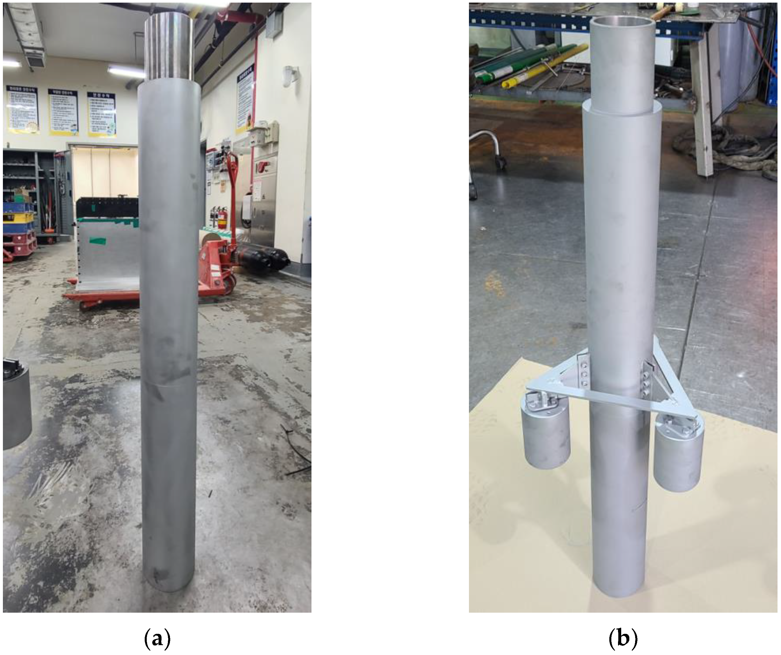
The additional structure of the hybrid monopile was composed of three suction buckets with an inner diameter (Di,b) of 5 m (in prototype) and a length (L) of 7 m (in prototype). These suction buckets were arranged at 120° intervals with respect to the monopile central axis at a distance of 2.5 m (0.5 Din) from the monopile. As previously mentioned, the actual additional support structure would be fixed in place by filling the space between the structure and monopile with a high-strength grouting material. However, to simplify the test, the additional structure and monopile were strongly connected with bolts in the scale model. In addition, the connections were reinforced with steel plates to minimize the structural deformation of the additional structure during loading. The finally constructed monopile model and hybrid monopile model weighed 7.05 and 9.80 kg, respectively, which corresponded to 1892 and 2630 tons based on the prototypes. Table 2 lists the detailed specifications of the prototypes and scale models for the target structures.

2.3. Experimental System

To simulate the lateral load on the monopile, an experimental system composed of a horizontal actuator, loading position controller, load cell, and clamp was constructed (Figure 3). The loading position controller, which was combined with the horizontal actuator, could control the height of the loading position, and a horizontal load (H) could be applied at the target height through the hinge-type clamp inserted into the upper part of the monopile. The clamp was made in a cylindrical shape to be inserted on top of the monopile. Teflon was inserted to the inside of the clamp because it has a smooth surface so that purely a horizontal load can be applied to the pile with low friction between the pile and clamp. When the horizontal actuator generated horizontal displacement at a constant rate for loading, the hinge-type clamp moved with the monopile to transmit the load to the foundation. In this instance, the horizontal load acting on the monopile was measured through the load cell installed between the clamp and loading position controller. The displacement and rotation angle of the monopile under the load were measured through non-contact laser sensors, and the axial force and bending moment acting on the monopile were measured using pairs of strain gauges installed in the longitudinal direction at multiple locations (see Figure 2). Four pairs of strain gauges were glued in opposite directions to measure the strain distributions.

2.4. Soil Sample Preparation

In this study, the bearing capacity of the hybrid monopile was evaluated under the seabed conditions of the southwest coast of Korea. Samples collected from the Saemangeum area of Gunsan, which is located on the southwest coast, were used in the model test. It was confirmed that the particle size distribution and mineral composition of the soil used were similar to the offshore site investigation data obtained at the target offshore wind farm site on the southwest coast [33].
The samples collected from the Saemangeum area were classified as silty sand (SM) according to the Unified Soil Classification System and the percentage passing sieve #200 was 47% (Table 3). The Saemangeum soil had a specific gravity (Gs) of 2.67 and maximum dry density (ρd,max) of 1650 kg/m3 based on the modified compaction method. It also had an optimal water content of 18.4%, a minimum dry density (ρd,min) of 1200 kg/m3, a minimum void ratio (emin) of 0.618, a maximum void ratio (emax) of 1.225, and a permeability of 1.5–2.0 × 10⁻⁶ m/s (Table 3). In addition, when a drained triaxial compression test was conducted, a maximum friction angle of 35.8° and residual friction angle of 35.5° were confirmed under a confining pressure range of 100–400 kPa [34]. Quartz represented the highest proportion (50–55%) of the Saemangeum samples, followed by feldspar (30%) and mica (10%). Fioravante (2002) evaluated the grain size effect on the pile behavior and proved that the grain size effect is minor when the ratio of model pile diameter to mean grain size is D/d50 > 100. Therefore, a limited effect on the pile behavior was expected because the D/d50 = 1370, which is greater than the criteria suggested by Fioravante (2002).
The model ground was prepared by compacting each layer using 13.5 kg circular weights (Figure 4). The height of each layer was 5 cm. The model seabed with a height of 550 mm was finally prepared by performing compaction on a total of 11 layers. To generate a uniform density for each layer, soil that corresponded to the target density considering the total volume and weight per each layer was prepared, mixed at the optimal water content (18.4%), and compacted in a soil box. In addition, to apply the same compaction energy to each layer, the circular weights were allowed to free fall from the same height and the same number of falls, and then the surface was refined. When the compaction was completed, the surface was scratched to minimize separation with the next soil layer. The samples were prepared in the same way and compaction was performed separately for 11 layers. When the compaction of all the layers was completed, tap water was dribbled from the surface for more than 12 h. The soil box was filled with water to a height of 3 cm from the ground surface to fully saturate the ground. Additional saturation was achieved by ramping up and down the centrifuge to the target g-level. Three separate soil samples were prepared for each lateral loading test. Each soil specimen condition is summarized in Table 1.

2.5. Experimental Condition

The centrifuge model test was conducted three times to analyze the behavior of the monopile and hybrid monopile installed in loose silty sand under lateral loading. In this instance, the specifications of the pile for the hybrid monopile, without the attached appendages, were the same as those of the conventional monopile. For the actual hybrid monopile, the appendages would be installed after the monopile. However, in the centrifuge model test, the appendages were strongly connected to the monopile with bolts installed on the ground to simplify the test.
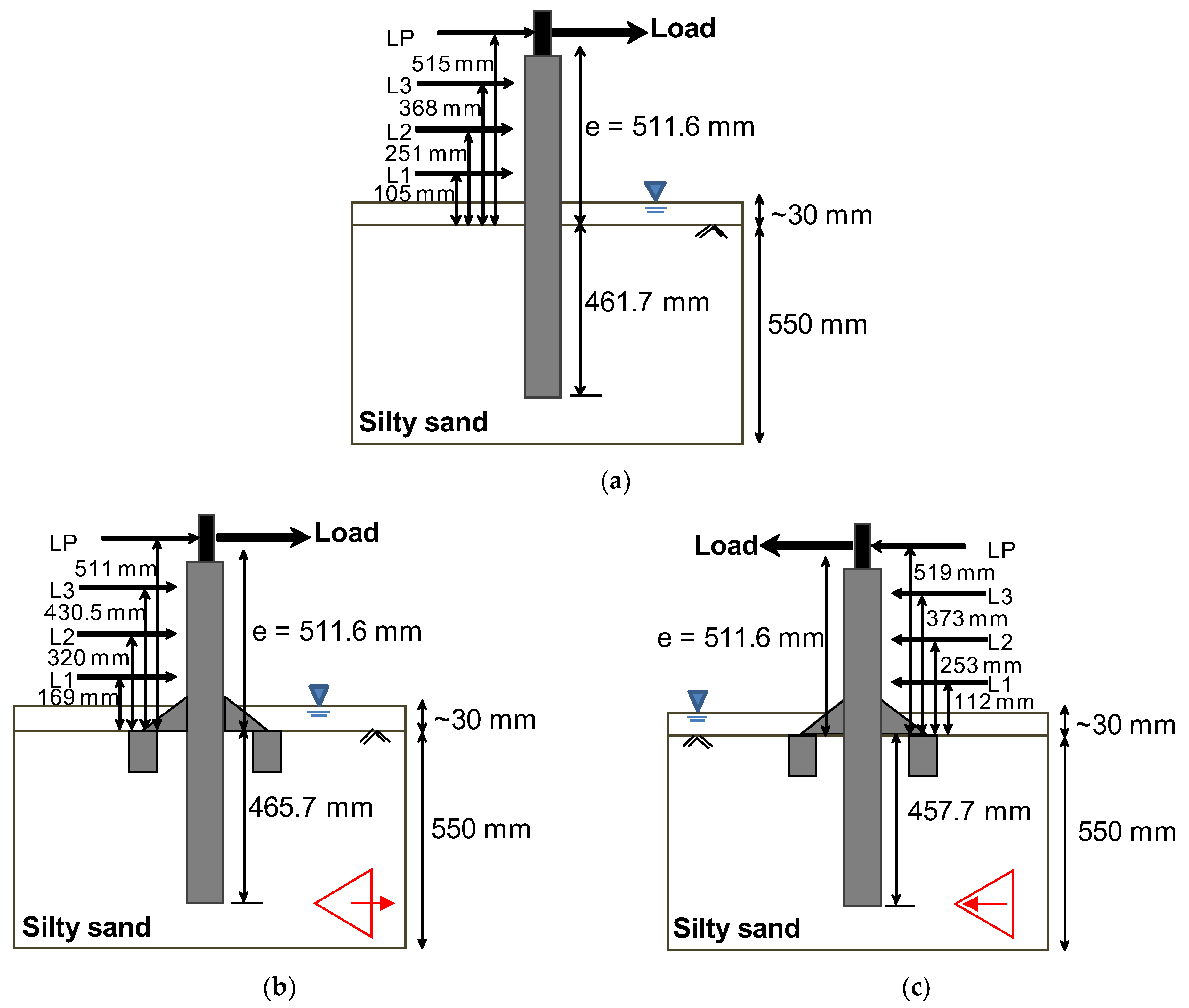
Prior to performing a centrifuge test, the model pile was installed in the center of model soil at a low speed of 0.5 mm/s using the vertical actuator. The penetration depth of the monopile from the seabed was set to 465.1 mm for all experiments (4.3 Do,p, where Do,p is the outer diameter of the monopile). The actual embedment depths were measured after installation and are marked in Figure 5. During the entire installation process, the verticality of the monopile was maintained at less than ±0.1°. It should be noted that the suction buckets of the hybrid monopile were strongly attached to the main pile so that they penetrated the seabed together with the monopile.
After the monopile installation, the horizontal loading system and sensors were positioned on the container and the monopile. In all the tests, loading was applied to a height of 511.6 mm (4.67 Do,p) from the seabed, which corresponded to 33 m above the seabed at the equivalent prototype (corresponding to 511.6 mm at 64.5 g). The loading height was selected considering the design load acting on the foundation for a 3 MW offshore wind turbine [33]. Figure 5 shows the sensor positions in each test.
For the hybrid monopile, because the buckets were installed at 120° intervals, the support behavior of the appendages varied depending on the loading direction. Therefore, in this study, the loading test was conducted for horizontal loading directions of 0° (T2, two buckets were compressed) and 180° (T3, one bucket was compressed) to compare the bearing capacities of the hybrid monopile according to the loading direction. Table 4 lists the conditions of the centrifuge model test.

2.6. Experimental Procedure

Each soil box where the model and loading system were installed was placed in the centrifuge basket, and each sensor was connected to the measurement system mounted on the centrifuge. The centrifuge was then accelerated at a rate of 3 g/min toward the target centrifugal acceleration. During the test, the ground settlement with centrifugal acceleration was observed using the linear variable differential transducers (LVDTs) installed on the soil container. When no more ground settlement was observed after reaching the target centrifugal acceleration, a miniature cone penetration test (mini CPT) was conducted to obtain the inflight soil profile.
A horizontal load was applied to the foundation using the horizontal actuator connected to the model at the target g-level (64.5 g). The static lateral load was applied to the monopile by moving the loading position controller connected to the monopile at a constant rate of 0.1 mm/s (see Figure 3) until the angle of rotation reached approximately 9°. This loading rate ensured a fully drained condition in the soil [34]. The lateral load applied to the monopile and its displacement were monitored in real-time during the test. The load test was conducted until the angle of rotation reached the target angle of rotation (i.e., 9°). Then, the load acting on the monopile was released by moving the actuator in the reverse direction until the load measured through the load cell reached zero to prevent the additional soil deformation from the residual load. The centrifuge test was then terminated.

3. Test Results

3.1. Cone Penetration Test

To evaluate the inflight properties of the soil, the cone tip resistance (qc) of each soil sample was acquired by conducting a mini CPT at the target g-level (64.5 g). The test was conducted using a miniature cone with a diameter of 10 mm, length of 350 mm, and tip angle of 60°. After reaching the target g-level, the cone was penetrated into the seabed to a depth of 300 mm at a rate of 1 mm/s. Here, it was not possible to perform the CPT to cover the whole embedment depth of the monopile (i.e., Lpile = 465.1 mm) due to the length limitation of the CPT.
Figure 6 shows the qc with the depth measured through the test. All values are in prototypes considering the centrifuge scaling law [24]. Here, the prototype depth can be calculated as the dimensions of the model scale multiplied by N, which is the centrifuge acceleration (i.e., N = 64.5). The qc profile for T2 was excluded from the results because the CPT could not be conducted as a result of the malfunctioning of the experimental equipment. The results show that the cone tip resistance increased nonlinearly as the depth increased in all the tests. The qc values in each test were similar for depths of 0–5 m, but differed significantly at depths of more than 5 m. At a maximum penetration depth of 14 m, qc ranged from 3.74 to 5.46 MPa. Kim et al. [35] proposed a method for estimating the relative density using the qc value acquired from Saemangeum sand. When the relative densities were estimated using the qc values acquired from the tests, they were found to be 41% (T1) and 37% (T3), respectively. Errors of less than 10% were observed compared to the relative density measured from the weight and volume of the actual ground. Meanwhile, it appeared that the qc values of the tests differed as a result of local density differences at different positions on the seabed created by compaction.

3.2. Load-Rotation Behavior

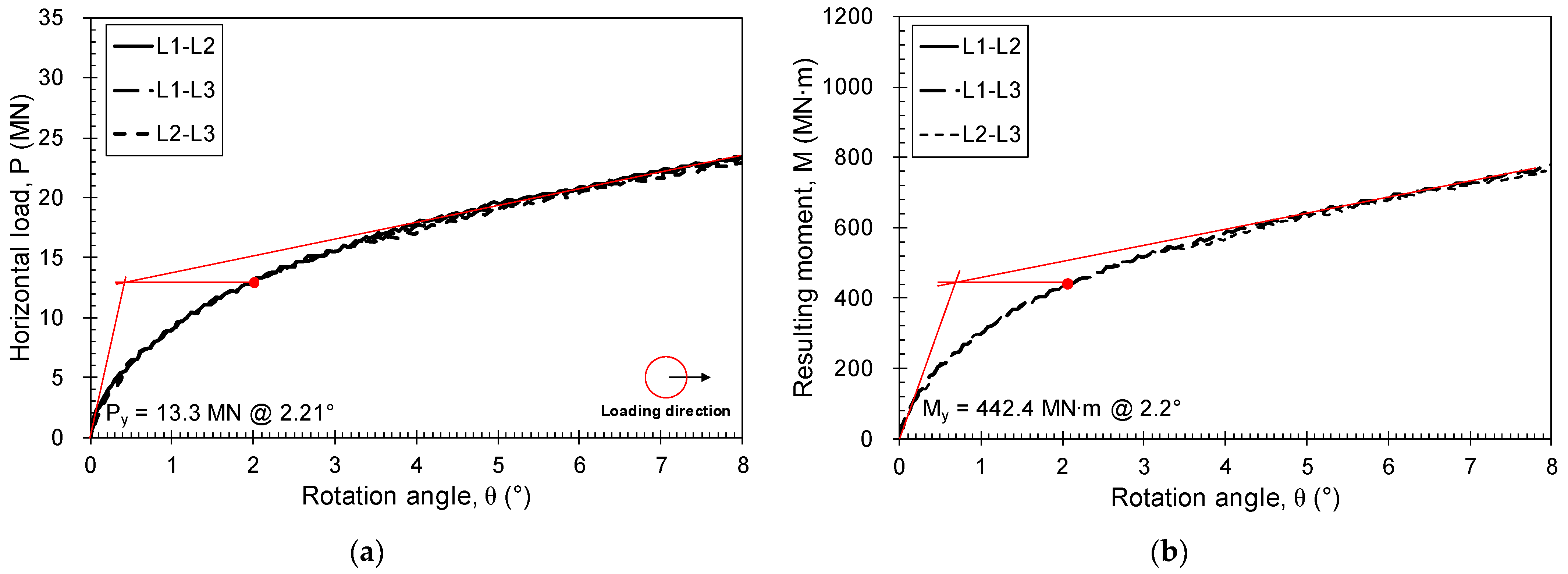
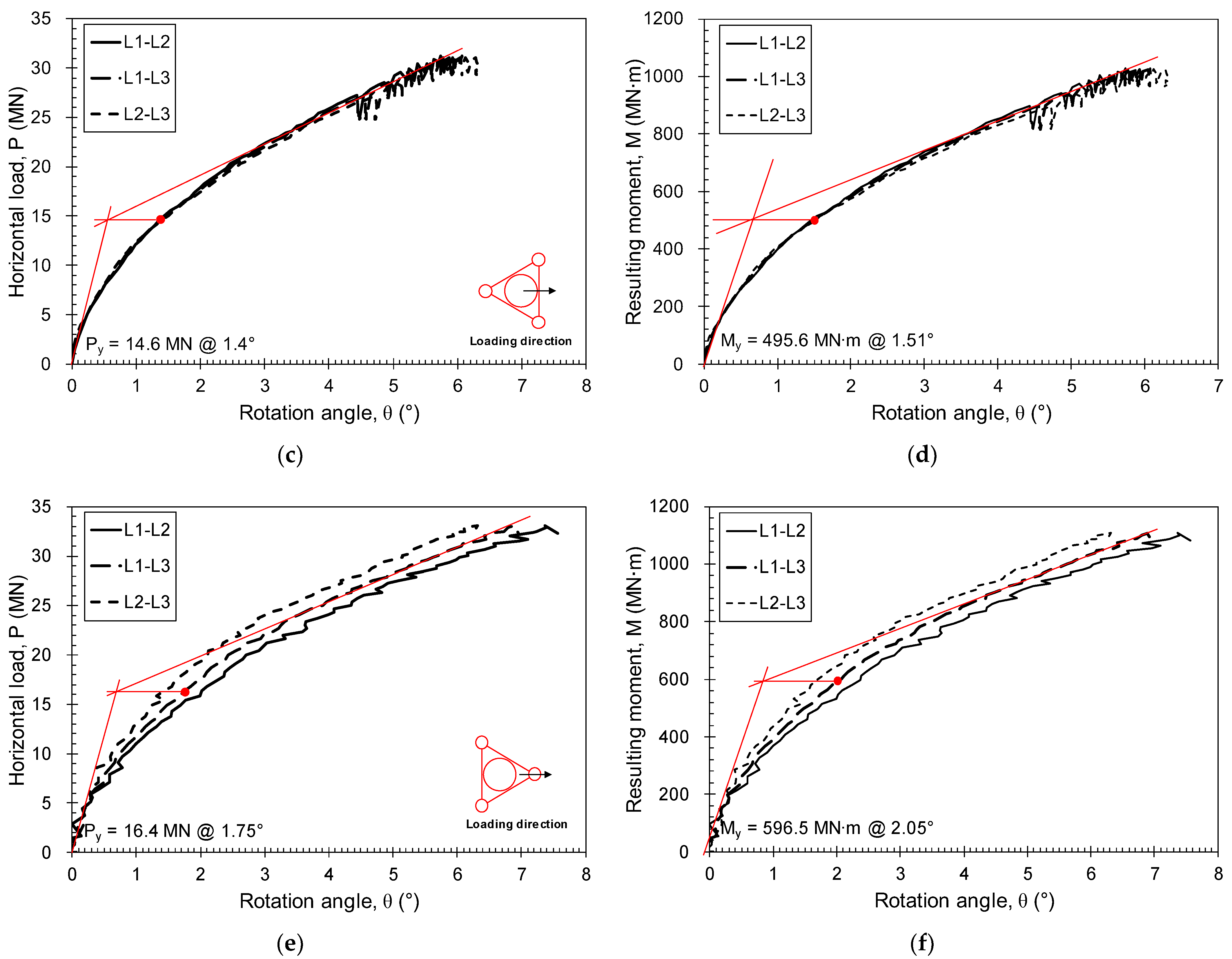
Figure 7a,c,e show the horizontal loads according to the rotation angle (θ) for the monopile and hybrid monopile. The rotation angle was calculated using measurements with two of the laser sensors installed at four positions in the longitudinal direction of the monopile. Here, the letters noted in the graph legend represent the sensor name used to calculate the rotation angle of the monopile (see Figure 5).
Consequently, the same values were observed from all the graphs regardless of the positions of the laser sensors, indicating that the monopile exposed above the seabed had a rigid body behavior rather than bending behavior within the applied load range. The resistance force significantly increased with the rotation angle under small loads. However, as the rotation angle gradually increased, the increment in the resistance force showed a tendency to gradually decrease. Villalobos [36] defined the yield resistance of the foundation (Py) as a point at which the line parallel to the axis from the intersection between the tangent line of the initial curve and that of the straight-line section after yielding in the load-rotation angle graph meets the graph (filled circle in Figure 7).
The yield resistances determined with the Villalobos method were Py = 13.3 MN (θ = 2.21°) for T1 (monopile), Py = 14.6 MN (θ = 1.4°) for T2 (hybrid monopile), and Py = 16.40 MN (θ = 1.75°) for T3 (hybrid monopile), respectively. This confirmed that the yield resistance increased by 1.10–1.23 times in the hybrid monopile with the additional structure compared to the case with no additional structure in the same seabed condition. The rotation angle under the yield load was smaller for the hybrid monopile (1.4° to 1.75°) compared to the monopile (2.21°), confirming that the additional structure of the hybrid monopile was effective in increasing the rotation resistance of the foundation.
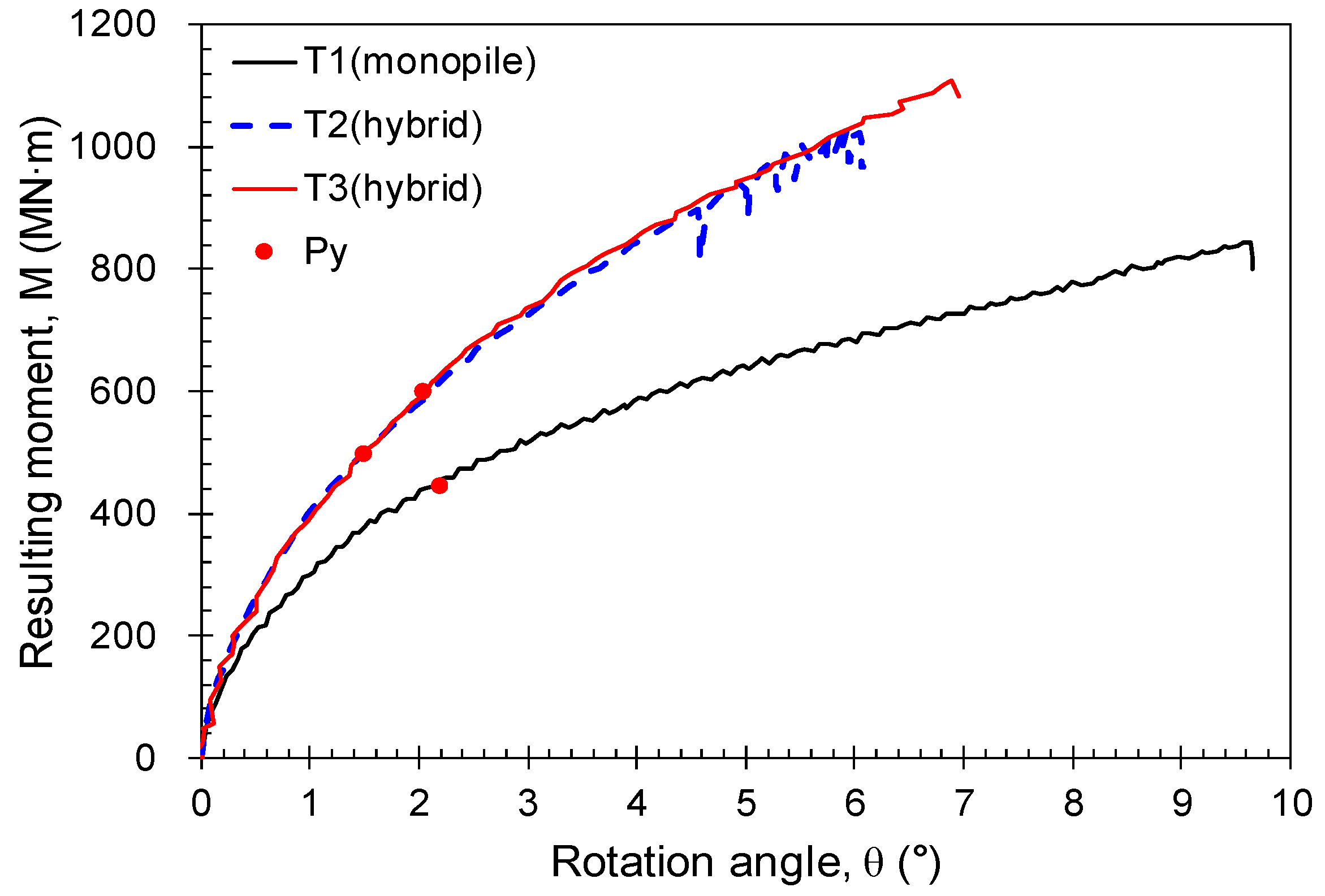
Figure 7b,d,f show the moment load (My) acting on the foundation using the horizontal load based on the seabed. The moment load was calculated by multiplying the horizontal load by the distance from the seabed to the loading point. When the yield moment was calculated using the method of Villalobos [36], the results were My = 442.4 MN·m (θ = 2.2°) for T1 (monopile), My = 495.6 MN·m (θ = 1.51°) for T2 (hybrid monopile), and My = 596.5 MN·m (θ = 2.05°) for T3 (hybrid monopile). The yield moment of the hybrid monopile with the appendages was 1.12–1.35 times higher than that of the monopile. Table 5 summarizes the lateral yield resistance and yield moment for each foundation type acquired from the tests.
Figure 8 shows the horizontal resistance in relation to the rotation angle for the monopile and hybrid monopile. Here, the angle of rotation was calculated from the lateral displacements for each position of the monopile exposed above the seabed. Under the same conditions, the resistance of the hybrid monopile was found to be higher than that of the monopile. In addition, as the rotation angle increased, the hybrid monopile exhibited a higher bearing capacity than the monopile. This was because the three-bucket foundation attached to the hybrid monopile increased the bearing capacity by increasing the resistance area of the seabed. In addition, the horizontal resistances in relation to the rotation angle of the hybrid monopile were similar for horizontal load directions of 0° (direction between buckets) and 180° (direction toward a bucket), confirming that the change in bearing capacity caused by the load direction was insignificant. However, the resistance mechanism of the appendages of the hybrid monopile differed with the load direction. This is described in the following section.
Figure 9 compares the moment load according to the rotation angle for each foundation type. The moment load was calculated by multiplying the applied horizontal load by the height of the horizontal load from the seabed (i.e., M = H × e). The moment resistance of the hybrid monopile was also higher than that of the monopile. As the rotation angle increased, the bearing capacity improvement ratio of the hybrid monopile compared to the monopile gradually increased.
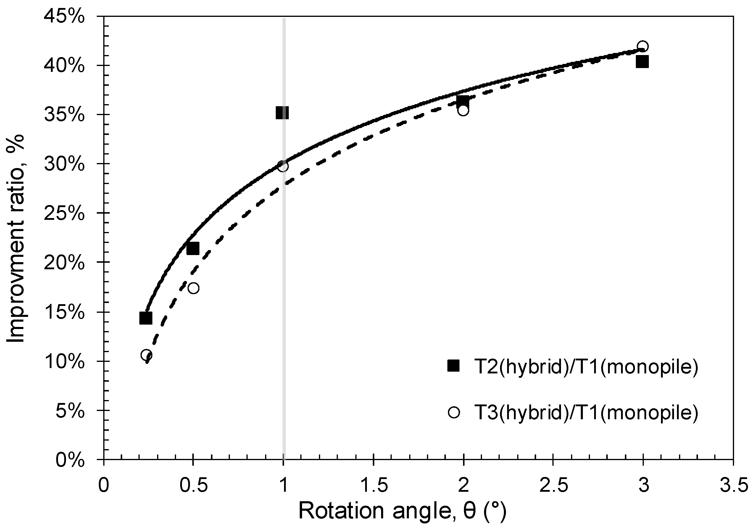
Figure 10 shows the bearing capacity improvement ratio of the hybrid monopile compared to the monopile according to the rotation angle. The bearing capacity improvement ratio dramatically increased as the rotation angle increased at a rotation angle of less than 1°. When the rotation angle exceeded 1°, the improvement ratio gently increased. This indicated that a large-diameter monopile mainly supports the lateral load when it is small (a small rotation angle), but the resistance of the additional structure to the lateral load increases with the lateral load (an increase in the rotation angle). The additional structure increases the bearing capacity of the entire system by increasing the resistance area of the ground against the lateral load. This finding was also supported by Kim et al. [22]. Kim et al. [22] performed a numerical simulation to evaluate the lateral behavior of a hybrid monopile. They found that the lateral movements of a single monopile cannot be constrained after the soil reaches the ultimate state, while the wider soil around the hybrid monopile is constrained by the additional structure, resulting in increased load capacity. They also showed that the additional structure helped to distribute the external loads and resulted in the transfer of the lateral load to the vertical, as the additional structure is located at a distance from the center of the monopile.
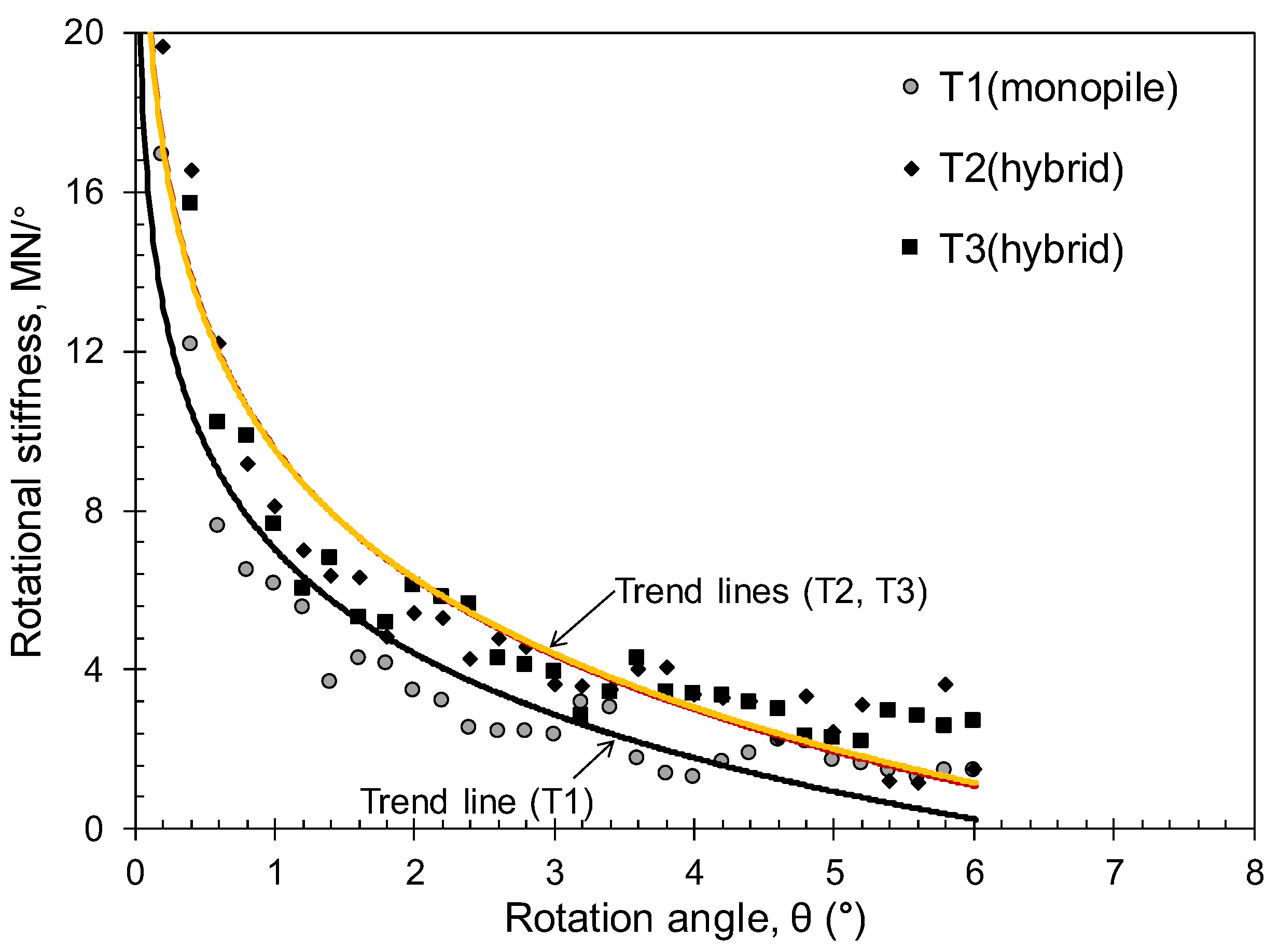
In addition to the bearing capacity, the stiffness of the foundation plays an important role in the behavior of the entire offshore wind tower system because the stiffness of the foundation affects the natural period of the system, which can lead to the resonance [31]. Figure 11 shows the rotational stiffness according to the rotation angle. Here, the rotational stiffness indicated the tangential slope of the load-rotation curve. As the rotation angle increased, the rotational stiffness decreased nonlinearly, which was typical behavior of the monopile. The change in the rotational stiffness was significant when the rotation angle was less than 1°, but when the angle exceeded 1°, the rotational stiffness gradually converged. In addition, the rotational stiffness was similar for all tests at the beginning of the rotation, but the difference in the stiffness was obvious at the large rotation. For an angle of rotation greater than 1°, the rotational stiffness of the hybrid monopile was approximately 1.6 times greater than that of the monopile. This indicated that the additional support structure installed around the monopile was effective in increasing the rotational stiffness, as well as the bearing capacity.

3.3. Bending Moment Acting on the Monopile

Figure 12 shows the strain measured with the strain gauge attached to the monopile wall in the longitudinal direction (see Figure 2). Here, a negative (-) strain represents the compression of the member. It can be seen that a compressive force was generated in the loading direction (A side in Figure 12), while a tensile strain occurred in the opposite direction (B side in Figure 12). For the monopile (T1), the strain increased as the depth from the seabed increased to 7 m in the loading direction (A side), but it gradually decreased afterward. This phenomenon was also observed for T2. In the case of T3, a high compressive strain occurred near the seabed in the loading direction (A side). This was because an excessive stress was concentrated at the connection between the monopile and additional structure (the distance of the strain gauge closest to the connecting plate (i.e., S1 noted in Figure 2) was only 10 mm).
The bending strain at each position of the monopile was measured using a pair of strain gauges installed at both sides of the monopile cross-section:
ɛ M = ( ɛ f + ɛ b ) 2 ,
where ɛ M is the bending strain acting on the cross-section, and ɛ f and ɛ b are the strain values measured with the strain gauges installed on both sides. Then, the bending moment could be calculated using the following equation:
M = ɛ M E Z ,
where M is the bending moment, E is the elastic modulus of the material, and Z is the section modulus (= I d 2 / 2 = π ( d 2 4 d 1 4 ) 32 d 2 , where I is the moment of inertia for the cross-section and d 2 a n d d 1 represent the outer and inner diameters of the monopile, respectively).
In addition, the bending moment of the actual prototype could be calculated from the measured values using the centrifuge scaling law:
E m I m = 1 N 4 E p I p ,
where E m I m and E p I p are the flexural rigidities of the model and prototype, respectively, and N is the centrifugal acceleration.
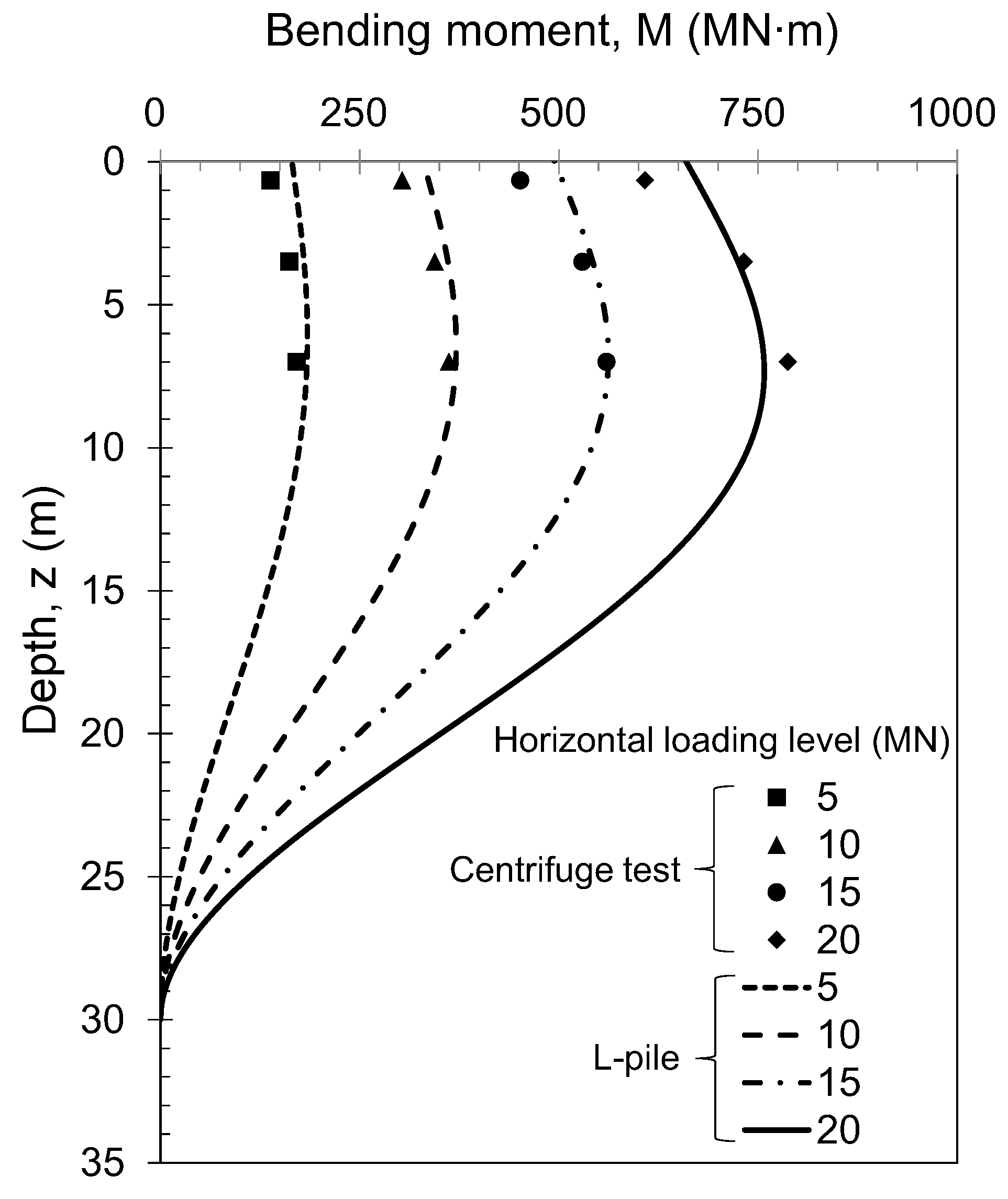
Figure 13 shows the measured bending moment in relation to the horizontal load applied to the monopile (T1). Because the strain gauges were installed within a depth of 2Lb (Lb: height of the supplementary buckets) from the seabed out of consideration for damaging strain gauges attached to the monopile wall, only the bending moment results within that depth are shown. An additional analysis was carried out using the commercial program, L-pile [37], to evaluate the bending moment acting on the pile at each location and these results are also plotted together in the figure. The L-pile program is widely used for analyzing the behavior of a pile against a lateral load, and is based on the p-y curve method of the API code. In the analysis, the input parameters were selected according to the specifications of the pile, load, and soil conditions in the test. Similar tendencies in the bending moments were found between the test and analysis results. Meanwhile, the tendency of the bending moment to increase with the load was confirmed. The bending moment increased with the depth from the seabed, reaching its maximum value at a depth of 0.95–1.12 Do,p. The bending moment then decreased as the depth increased. In general, it is known that the maximum bending moment acting on a structure under a horizontal load occurs at a depth of 1–1.5 D, and similar results were found in this study [38,39]. The maximum bending moment that occurred at a relatively shallow depth was caused by the large moment load acting on the monopile, indicating that excessive stress and deformation were concentrated near the seabed.
Figure 14 shows the bending moment for each test. In the test results, the bending moments acting on T2 and T3 (hybrid monopile) decreased to a level of approximately 88% at a depth of 7 m (1 Do,p) compared to T1 (monopile). This was because the additional structure reduced the bending stress of the pile, which assisted in securing the structural stability of the monopile. In the case of the T3 hybrid monopile, a high local bending moment was observed near the ground surface due to significant strain generated under lateral loading (see Figure 12). This was because the stress generated with the resistance of the additional structure to the lateral load was transmitted to the monopile through the reinforcing steel plate. Thus, it seems to be necessary to consider a structure that can disperse the stress during the detailed design of the connection between the additional support structure and monopile.
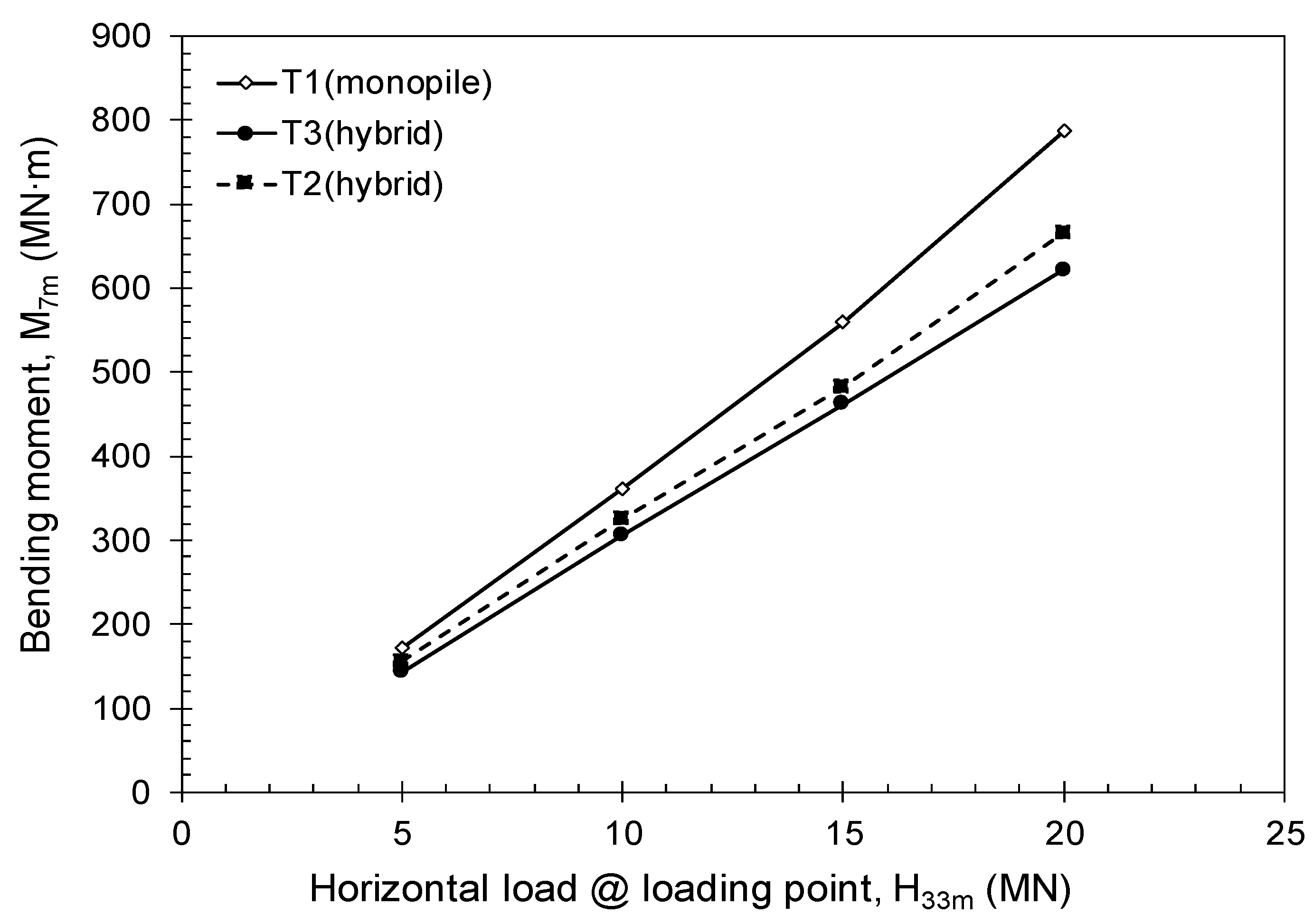
Figure 15 shows the moment measured near a depth of 7 m (i.e., S3 noted in Figure 2) from the seabed in relation to the applied lateral load. The monopile and hybrid monopile showed similar moment values under small loads, but a relatively larger moment was applied to the monopile as the load increased. This finding also suggests that the contribution of the appendages increases in proportion to the load within the loading level applied to the test.

3.4. Load Sharing Mechanism of Appendages

Figure 16 shows the failure patterns of the pile and ground upon the completion of the centrifuge model tests. In fact, the surface failure line was not clearly visible to the naked eye after the test because the failure shapes were slightly disturbed with the removal of surface water. Nevertheless, the difference in the failure line between the tests is very significant from the approximate failure area obtained from the post-test inspection. For T1 (monopile), the ground failure was concentrated at the front and rear surfaces in the loading direction. However, in the cases of T2 and T3 (hybrid monopile), the suction buckets expanded the ground failure to a larger area in addition to the front and rear surfaces in the loading direction. T2 (hybrid) showed a large area of failure in front because two buckets were located in the loading direction. T3 (hybrid), however, showed a large area of failure even in the rear surface of the monopile because two buckets were located in the opposite direction to the loading direction. Because the failure areas were similar despite the difference in the ground failure geometries depending on the loading direction, the bearing capacity improvement effects compared to the existing monopile were similar. A similar bearing mechanism of the hybrid monopile was also revealed in the results of Kim et al. [22].
The results of this study confirmed that the appendages of the hybrid monopile, which were installed at a shallow depth around the monopile, significantly contributed to an improvement in the bearing capacity by sharing the stress of the structure under horizontal loading and dispersing the load to the surrounding ground. In addition, while the increment in the resistance load sharply decreased as a result of ground failure after the yield point for T1 (monopile), the bearing capacities increased even after the yield load for T2 and T3 (hybrid monopile) because the appendages developed an additional resistance force while increasing the area of the ground failure.

4. Conclusions

In this study, centrifuge model tests were conducted to experimentally evaluate the lateral resistance mechanism of a hybrid monopile and examine the bearing capacity improvement effect compared to a typical monopile. To this end, model ground samples were created using silty sand collected from the southwest coast of Korea, and the lateral load resistance mechanisms and bearing capacities of the monopile and hybrid monopile were compared using these centrifuge model tests. The results are as follows:
  • The yield resistance of the hybrid monopile was 1.10–1.23 times greater than that of the typical monopile in loose silty sand regardless of the lateral load direction. In addition, as the rotation angle increased, the bearing capacity improvement ratio of the hybrid monopile compared to the monopile significantly increased, thereby confirming the bearing capacity improvement effect of the hybrid monopile.
  • The hybrid monopile had a yield resistance 1.10–1.23 times greater than the conventional monopile in loose silty sand, independent of the lateral load direction. Furthermore, as the angle of rotation increased, the hybrid monopile showed a significantly higher load capacity than the conventional monopile, confirming the effectiveness of the hybrid monopile in improving load bearing capacity.
  • The rotational stiffness of the hybrid monopile was approximately 1.6 times higher than that of the monopile. This appeared to be because the additional structure improved the resistance performance against the lateral load.
  • The appendage of the hybrid monopile distributes the external load to the soil, thereby reducing the maximum moment acting on the monopile and improving structural stability.
  • When the ground failure results were observed after the centrifuge model tests, it was confirmed that the additional structure of the hybrid monopile could induce larger ground resistance compared to the monopile by increasing the area of the ground failure.
The study evaluated the load capacity under static lateral loading based on the presence or absence of the appendage (i.e., conventional monopile vs. hybrid monopile). The deformation of the additional structure was not considered under the assumption that the additional structure was strongly connected to the monopile. Moreover, the cyclic behavior of the hybrid monopile caused by environmental loads such as a storm event was also not considered. Therefore, the results of this study were confined to the experimental conditions presented in this study, and further research is required on the cyclic loading behavior using a realistically simulated hybrid monopile.

Author Contributions

Conceptualization, J.-H.L., Y.-J.J. and T.-Y.K.; data curation, J.-H.K. and J.-H.L.; writing—original draft preparation, J.-H.K.; writing—review and editing, J.-H.L. and J.P.; supervision, Y.-J.J.; project administration, Y.-J.J.; formal analysis, J.-H.K. and T.-Y.K.; investigation, J.-H.K. All authors have read and agreed to the published version of the manuscript.

Funding

This research was supported by the Korean Institute of Energy Technology Evaluation and Planning (KETEP) and grant funded by the Korean government (MOTIE) (No. 20208520130010, Development of hybrid monopile technology based on frictional resistance for offshore wind turbine). This work was also supported by the National Research Foundation of Korea (NRF) and grant funded by the Korean government (MSIT) (No. NRF-2021R1C1C1011540). This work was also supported by 2022 Research Grant from Kangwon National University.

Institutional Review Board Statement

Not applicable.

Informed Consent Statement

Not applicable.

Data Availability Statement

Not applicable.

Conflicts of Interest

The authors declare no conflict of interest.

References

  1. World Forum Offshore Wind. Global Offshore Wind Report 2021. Available online: https://wfo-global.org/wp-content/uploads/2022/02/WFO_Global-Offshore-Wind-Report-2021.pdf (accessed on 17 July 2023).
  2. Matlock, H. Correlation for design of laterally loaded piles in soft clay. In Proceedings of the Offshore Technology Conference, Houston, TX, USA, 21–23 April 1970; pp. 77–94. [Google Scholar]
  3. Reese, L.C.; Cox, W.R.; Koop, F.D. Analysis of Laterally Loaded Piles in Sand. In Proceedings of the Offshore Technology Conference, Houston, TX, USA, 5–7 May 1974; pp. 473–483. [Google Scholar]
  4. API. Geotechnical and Foundation Design Considerations, ANSI/API Recommended Practice 2 GEO, 1st ed.; API: Washington, DC, USA, 2011. [Google Scholar]
  5. DNV. Support Structures for Wind Turbines (DNVGL-ST-0126); Det Norske Veritas: Bærum, Norway, 2018. [Google Scholar]
  6. Kim, J.H.; Jeong, Y.H.; Ha, J.G.; Park, H.J. Evaluation of Soil–Foundation–Structure Interaction for Large Diameter Monopile Foundation Focusing on Lateral Cyclic Loading. J. Mar. Sci. Eng. 2023, 11, 1303. [Google Scholar] [CrossRef]
  7. Jostad, H.P.; Grimstad, G.; Andersen, K.H.; Saue, M.; Shin, Y.; You, D. A FE procedure for foundation design of offshore structures–applied to study a potential OWT monopile foundation in the Korean Western Sea. Geotech. Eng. J. SEAGS AGSSEA 2014, 45, 63–72. [Google Scholar]
  8. Wang, X.; Zeng, X.; Li, X.; Li, J. Investigation on offshore wind turbine with an innovative hybrid monopile foundation: An experimental based study. Renew. Energy 2019, 132, 129–141. [Google Scholar] [CrossRef]
  9. Byrne, B.; McAdam, R.; Burd, H.; Houlsby, G.; Martin, C.; Zdravković, L.; Taborda, D.; Potts, D.; Jardine, R.; Sideri, M.; et al. New design methods for large diameter piles under lateral loading for offshore wind applications. In Proceedings of the International Symposium on Frontiers in Offshore Geotechnics, Oslo, Norway, 10–12 June 2015; pp. 705–710. [Google Scholar]
  10. Duhrkop, J.; Grabe, J. Improving of lateral bearing capacity of monopiles by welded wings. In Proceedings of the 2nd International Conference on Foundations, Las Vegas, NV, USA, 24–27 June 2008; HIS BRE Press: Garston, UK, 2008; pp. 849–860. [Google Scholar]
  11. Dührkop, J.; Grabe, J. Design of laterally loaded piles with bulge. In Proceedings of the 28th International Conference on Ocean, Offshore and Arctic Engineering, OMAE, HI, USA, 31 May–6 June 2009. [Google Scholar]
  12. Bienen, B.; Dührkop, J.; Grabe, J.; Randolph, M.F.; White, D.J. Response of piles with wings to monotonic and cyclic lateral loading in sand. J. Geotech. Geoenviron. Eng. 2012, 138, 364–375. [Google Scholar] [CrossRef]
  13. Dixon, R.K. Marine Foundations. WO 2005/038146 28 April 2005. [Google Scholar]
  14. Stone, K.; Newson, T.; Sandon, J. An Investigation of the Performance of a ‘Hybrid’ Monopile-footing Foundation for Offshore Structures. In Proceedings of the 6th International Offshore Site Investigation and Geotechnics Conference: Confronting New Challenges and Sharing Knowledge, London, UK, 11–13 September 2007; pp. 11–13. [Google Scholar]
  15. Arshi, H.S.; Stone, K.J.L. Lateral resistance of hybrid monopile-footing foundations in cohesionless soils for offshore wind turbine. In Proceedings of the 7th International Conference on Offshore Site Investigation and Geotechnics, London, UK, 2–6 September 2012. [Google Scholar]
  16. Arshi, H.S.; Stone, K.J.L.; Vaziri, M.; Newson, T.A.; El-Marassi, M.; Taylor, R.N.; Goodey, R.J. Modelling of monopile-footing foundation system for offshore structures in cohesionless soils. In Proceedings of the 18th International Conference on Soil Mechanics and Geotechnical Engineering, Paris, France, 2–6 September 2013. [Google Scholar]
  17. Wang, X.; Zeng, X.; Li, J.; Yang, X. Lateral bearing capacity of hybrid monopile-footing foundation for offshore wind turbines by centrifuge modelling. Ocean Eng. 2018, 148, 182–192. [Google Scholar] [CrossRef]
  18. Wang, X.; Zeng, X.; Yang, X.; Li, J. Feasibility study of offshore wind turbines with hybrid monopile foundation based on centrifuge modeling. Appl. Energy 2018, 209, 127–137. [Google Scholar] [CrossRef]
  19. Li, L.C.; Liu, X.; Liu, H.; Wu, W.B.; Lehane, B.M.; Jiang, G.S.; Xu, M.J. Experimental and numerical study on the static lateral performance of monopile and hybrid pile foundation. Ocean Eng. 2022, 255, 111461. [Google Scholar] [CrossRef]
  20. Chen, D.; Gao, P.; Huang, S.S.; Li, C.S.; Yu, X.G. Static and dynamic loading behavior of a hybrid foundation for offshore wind turbines. Mar. Struct. 2020, 71, 102727. [Google Scholar] [CrossRef]
  21. Fu, Z.; Wang, G.; Yu, Y.; Shi, L. Model test study on bearing capacity and deformation characteristics of symmetric pile–bucket foundation subjected to cyclic horizontal load. Symmetry 2021, 13, 1647. [Google Scholar] [CrossRef]
  22. Kim, J.; Jeong, Y.-J.; Park, J.; Lee, J.-H.; Kwak, T.; Kim, J.-H. Experimental and Finite Element-Based Investigation on Lateral Behaviors of a Novel Hybrid Monopile. Energies 2022, 15, 9095. [Google Scholar] [CrossRef]
  23. Kim, D.S.; Kim, N.R.; Choo, Y.W.; Cho, G.C. A newly developed state-of-the-art geotechnical centrifuge in Korea. KSCE J. Civ. Eng. 2013, 17, 77–84. [Google Scholar] [CrossRef]
  24. Garnier, J.; Gaudin, C.; Springman, S.M.; Culligan, P.J.; Goodings, D.; Konig, D.; Kuter, R.; Phillips, M.F.; Randolph, M.F.; Thorel, L. Catalogue of scaling laws and similitude questions in geotechnical centrifuge modelling. Int. J. Phys. Model. Geotech. 2007, 7, 1–23. [Google Scholar] [CrossRef]
  25. Kishida, H.; Uesugi, M. Tests of the interface between sand and steel in the simple shear apparatus. Géotechnique 1987, 37, 4–52. [Google Scholar] [CrossRef]
  26. Uesugi, M.; Kishida, H.; Uchikawa, Y. Friction between dry sand and concrete under monotonic and repeated loading. Soils Found. 1990, 30, 115–128. [Google Scholar] [CrossRef]
  27. Subba Rao, K.; Rao, K.; Allam, M.; Robinson, R. Interfacial friction between sands and solid surfaces. Proc. Inst. Civ. Eng. Geotech. Eng. 1998, 131, 75–82. [Google Scholar] [CrossRef]
  28. Porcino, D.; Fioravante, V.; Ghionna, V.N.; Pedroni, S. Interface behavior of sands from constant normal stiffness direct shear tests. Geotech. Test. J. 2003, 26, 289–301. [Google Scholar]
  29. Gavin, K.G. Experimental Investigations of Open and Closed-Ended Piles in Sand. Ph.D. Thesis, Trinity College, University of Dublin, Dublin, Ireland, 1998. [Google Scholar]
  30. Lehane, B.M.; Gavin, K.G. Base Resistance of Jacked Pipe Piles in Sand. J. Geotech. Geoenviron. Eng. 2001, 127, 473–480. [Google Scholar] [CrossRef]
  31. Arany, L.; Bhattacharya, S.; Macdonald, J.H.; Hogan, S.J. Closed form solution of Eigen frequency of monopile supported offshore wind turbines in deeper waters incorporating stiffness of substructure and SSI. Soil Dyn. Earthq. Eng. 2016, 83, 18–32. [Google Scholar] [CrossRef]
  32. Poulos, H.G.; Hull, T.S. The role of analytical geomechanics in foundation engineering. In Proceedings of the 1989 Foundation Engineering Conference, Evanston, IL, USA, 25–29 June 1989; pp. 1578–1606. [Google Scholar]
  33. Kim, D.-J.; Choo, Y.W.; Kim, J.-H.; Kim, S.; Kim, D.-S. Investigation of monotonic and cyclic behavior of tripod suction bucket foundations for offshore wind towers using centrifuge modeling. J. Geotech. Geoenviron. 2014, 140, 04014008. [Google Scholar] [CrossRef]
  34. Jeong, Y.H.; Lee, S.W.; Kim, J.H. Centrifuge modeling for the evaluation of the cyclic behavior of offshore wind turbine with tripod foundation. Appl. Sci. 2021, 11, 1718. [Google Scholar] [CrossRef]
  35. Kim, J.H.; Choo, Y.W.; Kim, D.J.; Kim, D.S. Miniature cone tip resistance on sand in a centrifuge. J. Geotech. Geoenviron. 2016, 142, 04015090. [Google Scholar] [CrossRef]
  36. Villalobos, F.A. Model Testing of Foundations for Offshore Wind Turbines. Ph.D. Thesis, University of Oxford, Oxford, UK, 2006. [Google Scholar]
  37. Reese, L.C.; Wang, S.T.; Isenhower, W.M.; Arrellaga, J.A. Computer Program Lpile Plus; Version 5.0 Technical Manual; Ensoft: Austin, TX, USA, 2004. [Google Scholar]
  38. Choo, Y.W.; Kim, D.; Park, J.H.; Kwak, K.; Kim, J.H.; Kim, D.S. Lateral response of large-diameter monopiles for offshore wind turbines from centrifuge model tests. Geotech. Test. J. 2014, 37, 107–120. [Google Scholar] [CrossRef]
  39. Haiderali, A.; Cilingir, U.; Madabhushi, G. Lateral and axial capacity of monopiles for offshore wind turbines. Indian Geotech. J. 2013, 43, 181–194. [Google Scholar] [CrossRef]
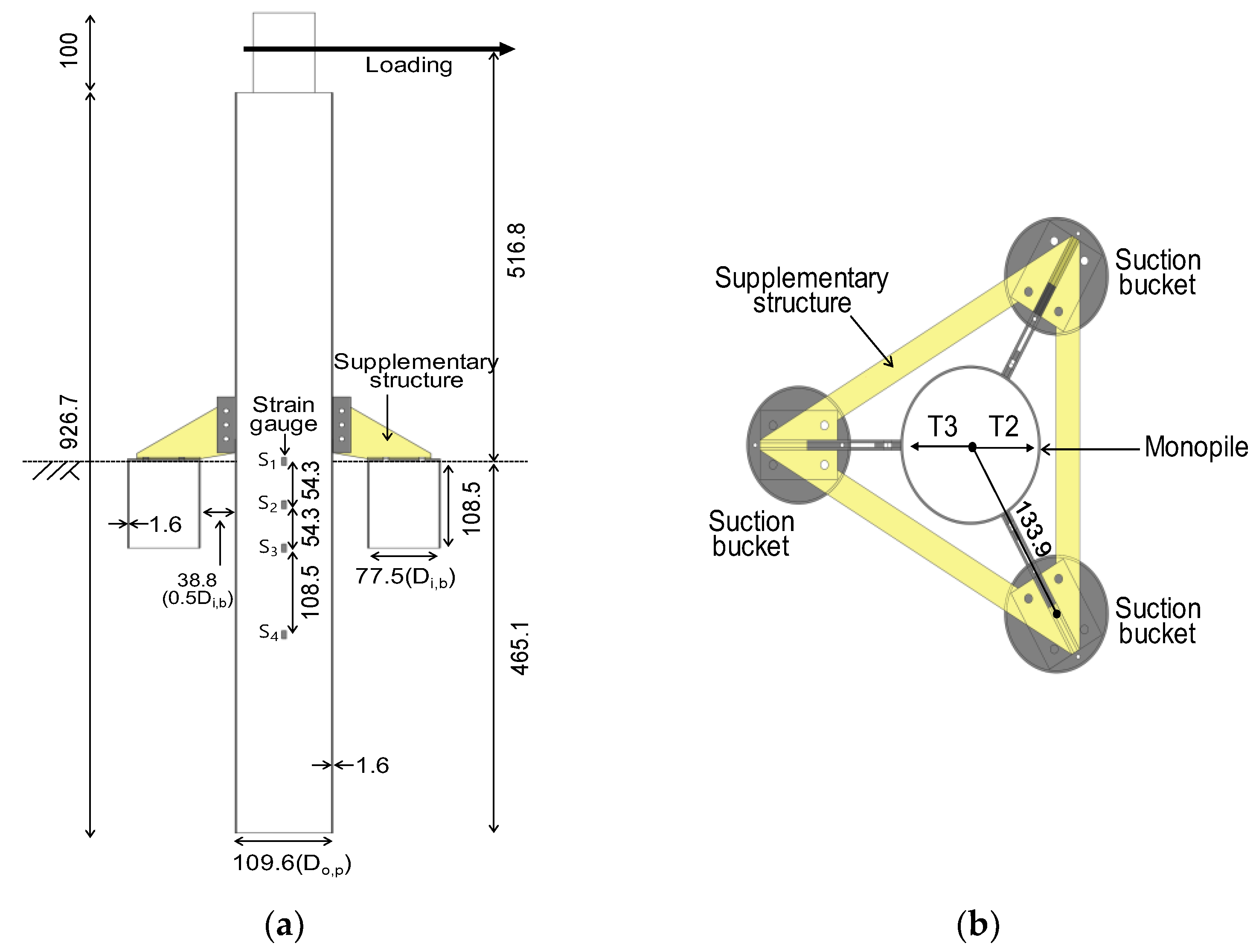
Figure 1. Scaled hybrid monopile (unit: mm): (a) side view; (b) plan view.
Energies 16 07234 g001
Figure 2. Small-scale model: (a) Monopile; (b) Hybrid monopile.
Energies 16 07234 g002
Figure 3. Photograph of the testing equipment.
Energies 16 07234 g003
Figure 4. Soil model preparation: (a) soil preparation layout; (b) soil compaction.
Energies 16 07234 g004
Figure 5. Experimental cross-section and sensor locations: (a) T1 (Monopile); (b) T2 (Hybrid); (c) T3 (Hybrid) (note: red triangle and arrows in the figure indicate the tripod cross-sectional shape of the hybrid monopile and the loading direction, respectively).
Energies 16 07234 g005
Figure 6. Cone tip resistance profile.
Energies 16 07234 g006
Figure 7. Load-rotation for monopile and hybrid monopile—(a) T1: horizontal load-rotation; (b) T1: moment-rotation; (c) T2: horizontal load-rotation; (d) T2: moment-rotation curve; (e) T3: horizontal load-rotation; (f) T3: moment-rotation curve (note: red point in the figure indicate yield resistance).
Energies 16 07234 g007aEnergies 16 07234 g007b
Figure 8. Horizontal load-rotation curves for monopile and hybrid monopile.
Energies 16 07234 g008
Figure 9. Moment load-rotation curves for monopile and hybrid monopile.
Energies 16 07234 g009
Figure 10. Lateral resistance improvement ratio of the foundation with the rotation angle.
Energies 16 07234 g010
Figure 11. Rotational stiffness with rotation angle.
Energies 16 07234 g011
Figure 12. Strain profiles of monopiles: (a) T1 (monopile); (b) T2 (hybrid monopile); (c) T3 (hybrid monopile).
Energies 16 07234 g012
Figure 13. Bending moment distribution (T1).
Energies 16 07234 g013
Figure 14. Bending moment profile with depth (for T1, data were limited to a depth of 7 m due to a malfunction of the strain gauge).
Energies 16 07234 g014
Figure 15. Bending moment trends with lateral load at depth of 7 m from the seabed.
Energies 16 07234 g015
Figure 16. Observations of soil failures after centrifuge tests (red lines indicate the soil failure zones): (a) T1 (monopile); (b) T2 (hybrid); (c) T3 (hybrid).
Energies 16 07234 g016
Table 1. Specification of KAIST centrifuge.
ItemsSpecifications
Platform radius5.0 m
Maximum capacity240 g-tons
Maximum acceleration130 g with 1300 kg payload
Maximum model payload2400 kg up to 100 g
Table 2. Dimensions of monopile and hybrid monopile models.
TypeItemPrototypeModel (1/64.5) *
MonopileExternal diameter (Do,p)7.07 m109.6 mm
Length (Lpile) **30 m465.1 mm
Tip thickness (tpile)104.5 mm1.62 mm
Loading height
from the seabed (e)
33 m515.6 mm
Elastic modulus (E)210 GPa210 GPa
Moment of inertia (I)13.29 m47.68 × 10−7 m4
Hybrid monopileMonopileExternal diameter (Do,p)7.07 m109.6 mm
Tip thickness (tpile)104.4 mm1.6 mm
Embedded depth (z)30 m465.1 mm
Loading height
from the seabed (e)
33 m516.8 mm
Supplementary
buckets
Internal diameter (Di,b)5 m77.5 mm
Length (Lb)7 m108.5 mm
Tip thickness (tbucket)104.1 mm1.6 mm
Pile–bucket spacing (s)2.5 m38.76 mm
* This value is the measured value after machining the model. ** The length of the pile driven into the seabed.
Table 3. Geotechnical properties of the tested soil.
ItemsSpecifications
Soil classification (USCS)SM
Maximum dry density, ρd,max (g/cm3)1.65
Minimum dry density, ρd,min (g/cm3)1.20
Mean grain size, d50 (mm)0.08
Specific gravity (Gs)2.67
Uniformity coefficient (Cu)2.11
Mean particle diameter, D50 (mm)0.08
Permeability, k (m/s)1.5–2.0 × 10−6
Peak friction angle ( φ p , °) *35.8
Residual friction angle ( φ c , °)35.5
* Drained triaxial compaction testing results for a sample with Dr = 40% under a confining pressure in the range of 100–400 kPa.
Table 4. Testing conditions.
Test NameLoading
Direction (°)
Soil Specimen Height (mm)Loading Height from the Seabed,
m for Prototype
Soil Water
Contents (%)
Wetted Soil
Density (tf/m3)
Soil Relative
Density, Dr * (%)
T1 (MP)
(Monopile)
055033 m16.31.5945.7
T2 (HB1)
(Hybrid monopile)
0
(direction of bucket)
18.41.5939.9
T3 (HB2)
(Hybrid monopile)
180
(direction of bucket to bucket)
18.71.5939.2
* Based on soil specimen weight and volume after completion of soil sample preparation.
Table 5. Summary of experiment results.
Test NameLoading
Direction (°)
Lateral Bearing Capacity, Py
(MN)
Improvement RatioResulting Moment Capacity, My *
(MN·m)
Improvement Ratio **
T1 (MP)
(Monopile)
013.3-442.4-
T2 (HB1)
(Hybrid monopile)
0
(direction of bucket)
14.61.23495.61.12
T3 (HB2)
(Hybrid monopile)
180
(direction of bucket to bucket)
16.41.10596.51.35
* Calculated by multiplying lateral load by loading height from the seabed. ** Ratio of lateral bearing capacity of hybrid monopile to that of the monopile.
Disclaimer/Publisher’s Note: The statements, opinions and data contained in all publications are solely those of the individual author(s) and contributor(s) and not of MDPI and/or the editor(s). MDPI and/or the editor(s) disclaim responsibility for any injury to people or property resulting from any ideas, methods, instructions or products referred to in the content.