1. Introduction
Addressing the urgent need to combat climate change by reducing carbon emissions in the transportation sector has become a top priority. Electric vehicles (EVs) have emerged as the vanguard of a more environmentally friendly future. At the core of these EVs lies their energy storage system, and lithium-ion batteries have emerged as the frontrunner due to their remarkable characteristics, including high energy density and minimal self-discharge [
1]. However, the sensitivity of lithium-ion batteries to excessive voltage and temperature underscores the necessity of implementing a sophisticated Battery Management System (BMS) to ensure the battery’s safe and reliable operation. The BMS plays a central role in real-time monitoring and the estimation of various cell states, encompassing critical parameters, such as the state of charge (SOC), state of health (SOH), state of energy (SOE), state of power (SOP), state of temperature (SOT), and state of safety (SOS) [
2].
The precise estimation of SOC is especially crucial, given its pivotal role in averting the overcharging and over-discharging of the battery cell. Nevertheless, it is important to note that the SOC cannot be directly measured; instead, it must be inferred from sensor measurements, such as the voltage and current. This inherent complexity makes the SOC estimation process a challenging endeavor [
3]. Addressing the urgent need to combat climate change by reducing carbon emissions in the transportation sector has become a top priority. Electric vehicles (EVs) have emerged as the vanguard of a more environmentally friendly future. At the core of these EVs lies their energy storage system, and lithium-ion batteries have emerged as the frontrunner due to their remarkable characteristics, including high energy density and minimal self-discharge [
1]. However, the sensitivity of lithium-ion batteries to excessive voltage and temperature underscores the necessity of implementing a sophisticated Battery Management System (BMS) to ensure the battery’s safe and reliable operation. The BMS plays a central role in real-time monitoring and the estimation of various cell states, encompassing critical parameters such as the state of charge (SOC), state of health (SOH), state of energy (SOE), state of power (SOP), state of temperature (SOT), and state of safety (SOS) [
2].
The accurate estimation of the SOC is of particular significance, as it plays a pivotal role in preventing overcharging and over-discharging of the battery cell. Nevertheless, it is essential to note that the SOC cannot be directly measured; instead, it must be inferred from sensor measurements, such as voltage and current. This inherent complexity makes the SOC estimation process challenging [
3]. In the past decade, various methods of SOC estimation have been proposed and mainly categorized into the ampere-hour integration method, model-based method, and data-driven method. The ampere-hour (Ah) integration method [
4] estimates straightforwardly by integrating currents over the whole operation period. Despite the simple operation, this method suffers from some distinct drawbacks, such as its inability to determine the initial SOC and the accumulation of measurement errors from the current sensor [
5]. Data-driven methods based on machine learning have gained interest thanks to their easy implementation because they do not require prior knowledge about the battery. This method takes temperature, current, and voltage measurements as input to the neural network to predict the SOC [
6,
7]. However, training the system takes much time and a dataset. Compared to the mentioned approaches, the model-based method, especially the Kalman filter (KF) family, is predominantly used for real-time applications [
8]. This method is preferable for SOC estimations because of its closed-loop nature, high accuracy, and significant noise rejection [
9]. The technique is accomplished through two processes, battery modeling and SOC estimation algorithm implementation. Indeed, the SOC accuracy highly depends on the battery model.
There are three main categories of lithium-ion battery models, the electrochemical model, the data-driven model, and the electrical equivalent circuit model (EECM). The EECM uses specific electrical components, such as voltage sources, capacitors, and resistors, to describe the dynamic characteristics of the battery. It offers relatively simple visualization and applicability merits. For this reason, it is preferable in a real BMS. Several EECMs with different structures have been presented in the literature [
10,
11,
12,
13,
14]. The Rint model is the simplest topology for an EECM, which consists of a voltage source and a series resistor. However, this model needs to be revised because it only describes the instantaneous voltage drop when a load has connected to the battery. To address this issue, a pair or resistor–capacitor network can be added to the system to represent the nonlinear polarization response. Reference [
10] compares Rint, Thevenin, and PNGV models. It concludes that the accuracy of the model will be improved as the order of the RC network increases but with the cost of higher computation complexity. A second-order EECM is recommended [
11] as it provides a balance between the accuracy and complexity of the model, as it is adopted by many researchers, such as in [
12,
13,
14].
After selecting the EECM type, estimating the model’s parameter is another challenge. Different parameter identification methods are proposed, such as optimization-based, curve fitting-based, and least-squares (LS)- or Recursive Least-Squares (RLS)-based techniques. The literature [
15,
16,
17] uses the first-order Thevenin model, and the model parameters are identified using the Recursive Least Square (RLS) and Extended Kalman Filter (EKF). In [
18,
19], a genetic algorithm (GA) and particle swarm optimization (PSO) are employed to search the best-fit parameters of the EECM parameters. The mentioned research mainly focuses on how to obtain better estimated battery parameters. However, the provided studies are often conducted under an ambient temperature of 25 °C [
20], excluding the impact of extreme temperatures. The properties of the battery are heavily affected by temperatures and can directly impact the battery’s performance. A study [
21] observed that cell capacity and the best SOC are reduced at subzero temperatures. Therefore, the parameter identification of the battery model under different temperatures, especially under extreme temperatures, can be relevant. Based on the global average and extreme temperature per month [
22], this study proposed a temperature-compensated battery mode, where the battery parameters are identified under five different temperatures (−20 °C, −10 °C, 0 °C, 25 °C, and 40 °C). Among parameter identification methods, the literature [
23] compares four optimization algorithms, and the trust-region reflective nonlinear least-squares (TR-NLS) achieves the best result with little computational effort. Thus, the TR-NLS is used in this study to identify the battery model parameters.
Numerous studies were performed regarding the LiB cell model, including changing the number of RC networks inside the model, parameters, and SOC estimation method. However, a single LiB cell cannot be used directly in EV applications because of its relatively low capacity and voltage. Therefore, the battery cells are combined to make a battery pack before being used. Nevertheless, to the best of the author’s knowledge, research regarding the battery pack for EVs still needs to be completed. Therefore, this study uses the proposed battery cell model with the identified parameters to build a battery pack. The single-cell model is connected in series and parallel configurations to achieve a higher total capacity and voltage. To assure safety, the Extended Kalman Filter (EKF) is proposed for SOC estimation, and a cooling plate is mounted to the bottom of the battery pack. The flow rate of the coolant liquid is controlled to reduce the maximum battery temperature.
In a notable contribution to the field, the main contribution is as follows:
This study strategically tackles the previously mentioned challenge by unveiling a multifaceted solution. It introduces an innovative battery pack model alongside an advanced Battery Management System (BMS), seamlessly incorporated into an electric vehicle (EV) model.
Through meticulous simulations encompassing four distinct urban driving scenarios, closely mirroring real-world conditions, the remarkable efficacy of the integrated EV-BMS model takes center stage.
The key innovation lies within the BMS itself, which boasts a cutting-edge EKF-based SOC estimation, a precision coolant-flow-control mechanism, and an ingenious passive cell balancing algorithm. This amalgamation of advancements collectively guarantees the safe and secure operation of the battery pack and its optimal performance in demanding real-world scenarios.
In essence, this research significantly amplifies the realm of EV technology by providing an inventive, holistic approach that promises to elevate EVs’ overall reliability and efficiency when navigating the intricacies of urban driving environments.
Additionally, a passive balancing algorithm with a shunt resistor is connected in parallel to each cell to reduce the SOC imbalance inside the battery pack. The proposed battery pack and BMS subsystems will then be added to the electric vehicle model as a contribution. Finally, the integrated EV-BMS model is simulated in a Simulink/MATLAB environment, with four urban driving cycles to affect an actual driving condition.
The rest of the paper is arranged as follows;
Section 2 introduces the modeling of the LiB cell, including the proposed EECM model, parameter identification process, and the battery model validation;
Section 3 presents the explanation of the proposed battery pack;
Section 4 describes the EKF algorithm for the SOC estimation, battery pack coolant flow rate algorithm, and the passive cell balancing proposed for the integrated Battery Management System (BMS); the proposed electric vehicle model with the battery pack and BMS will be provided in
Section 5;
Section 6 gives the analysis results; and the conclusions are drawn in
Section 7.
2. Battery Modeling
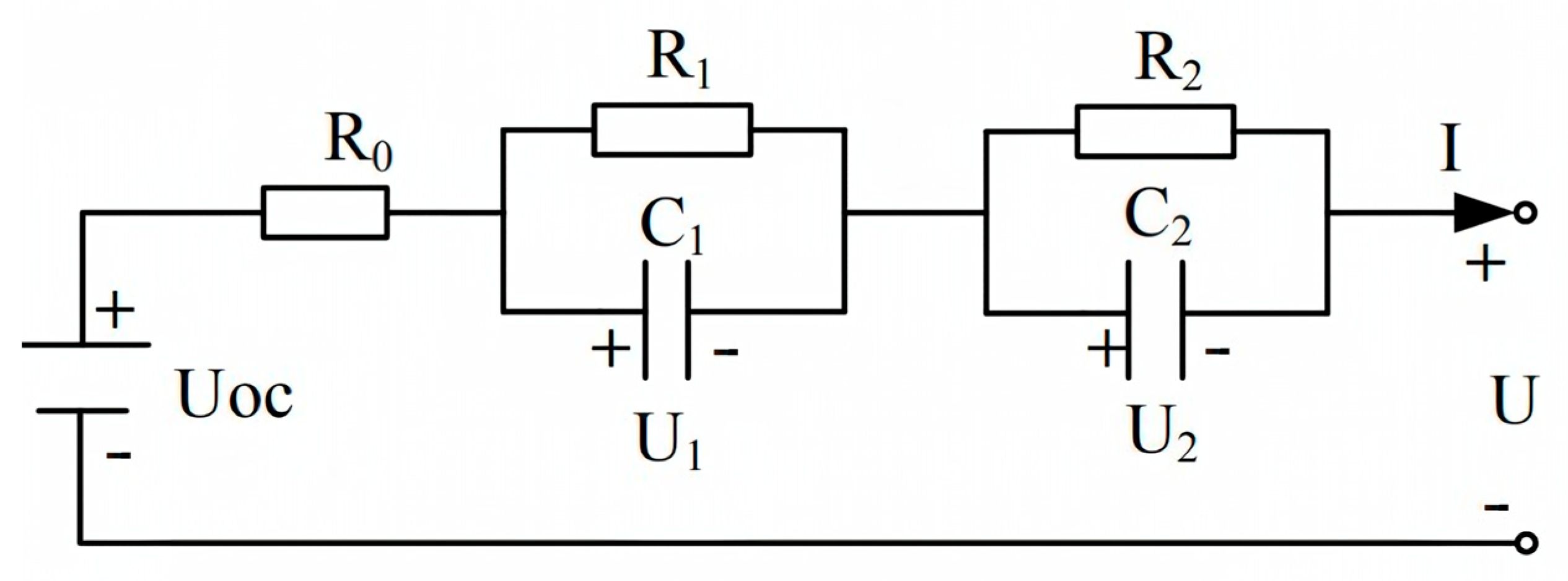
This section introduces the Thevenin model to mimic the battery behavior involving the voltage responses to a discharge pulse. A typical EECM uses electrical components to simulate the battery’s dynamic characteristics, such as the battery open-circuit voltage (OCV), internal resistance, and one or multiple pairs of the resistance-capacitance (RC) networks. Along with the increase in the RC network numbers, the accuracy will increase, but in addition to the order and complexity. Therefore, considering these factors, the second-order Thevenin model is chosen for this paper.
The schematic model is presented in
Figure 1, and the model equation based on Kirchhoff’s law can be obtained as follows:
where
U represents the measured voltage and
U1 and
U2 represent the voltage across the
R1-
C1 and
R2-
C2 pairs, respectively.
UOC is the battery OCV.
R0 is the internal resistance representing the instantaneous voltage drop when a load has connected to the battery system. The parallel RC networks represent the nonlinear polarization response of the battery.
R1 and
R2 are the polarization resistances;
C1 and
C2 are the polarization capacitances. Parameter
Q is the battery charge capacity in Ampere-second.
2.1. Experimental Data
In this study, the battery cell under test was an LG18650HG2, whose characteristics are reported in
Table 1. The reason for choosing the LG18650HG2 battery is that it is widely used in existing electric vehicles and has been proven to be a safe and reliable lithium-ion battery. In addition, this type of battery also has high safety performance, does not explode, does not burn; it has non-toxic, non-polluting, RoHS trademark certification; the cycle number is more than 500 times; it has good high-temperature performance; and discharge efficiency reaches 100% at 65 degrees. All experiments were performed by Dr. Phillip Kollmeyer at Wisconsin-Madison University [
21] and carried out in a thermal chamber presented in [
2]. The experimental data used are thfour-pulse discharge HPPC test. The cell is discharged at 1C, 2C, 4C, and 6C discharge rates and charged with four varying C-rates (0.5, 1, 1.5, and 2C). Based on recent data of the global average and extreme temperature [
22], the experiments were conducted at −20 °C, −10 °C, 0 °C, 25 °C, and 40 °C. The following data were measured during the experiment:
Test chamber ambient temperature (Celsius);
Measured current applied to the battery cell (A);
Measured cell’s terminal voltage (V);
Time of the test (s);
2.2. Battery Parameter Identification
Before using the model for estimating the battery SOC, the parameters must be identified offline to decrease the influence of uncertain parameters on the estimation effect [
24]. Temperature variation and the state of charge (SOC) influence the electrochemical behavior of lithium-ion cells [
25]. Therefore, this study identifies parameters at five different temperatures for 10 SOC breakpoints, so that each element of the equivalent circuit of
Figure 1 is a function of the SOC and temperature. The parameters to be identified are
R0,
R1,
R2,
C1,
C2, and
UOC.
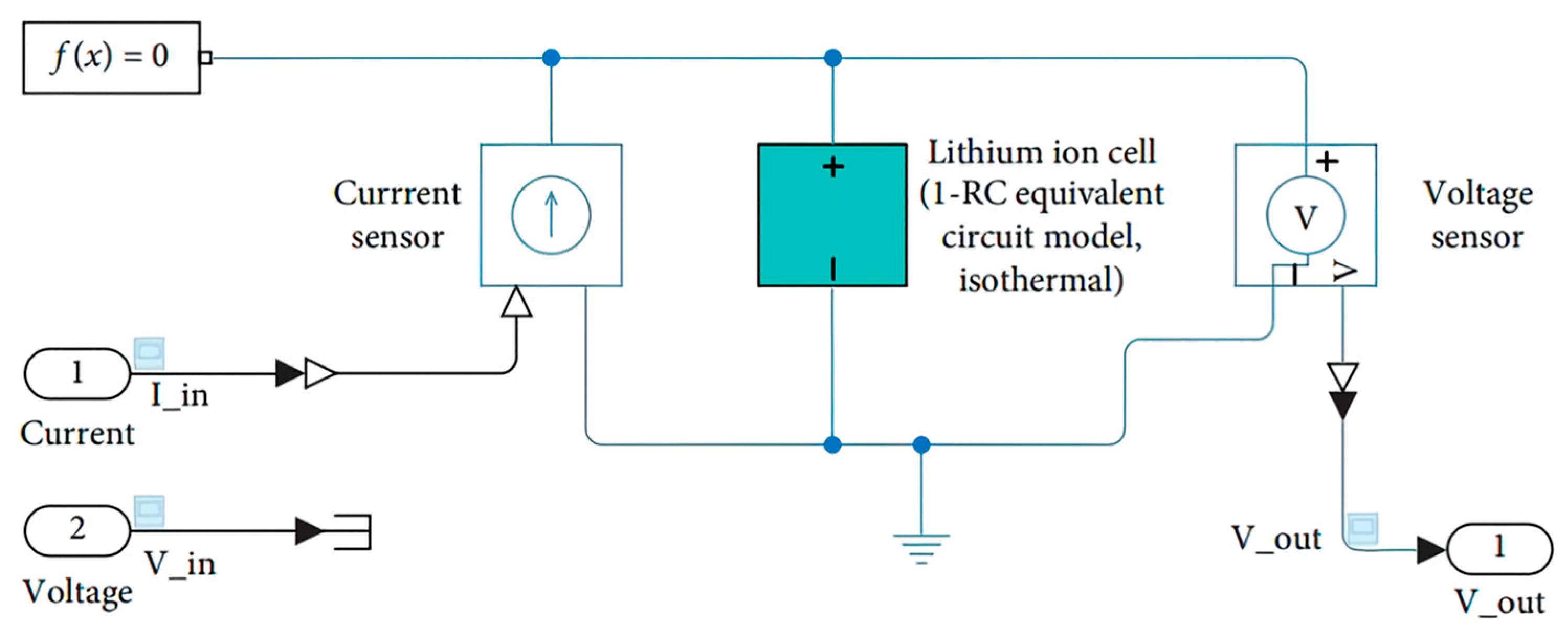
These parameters of the model were determined using the parameter estimator tool in Simulink Design Optimization.
Figure 2 illustrates the simulation environment of the model built with the Simscape library integrated with the MATLAB/Simulink environment. First, the current collected from the experimental data is connected to the battery model as the input and output of the simulated voltage through the simulation. Subsequently, the optimization toolbox is used to iteratively fit the simulated and actual voltage until the error meets the requirement.
As shown in
Figure 2, this study adopted the second-order Thevenin model with six parameters to be identified. The parameters are determined by applying the nonlinear least-squares method with the Trust-Region-Reflecting algorithm (NLS-TRRLS) to the measured experimental data. The NLS-TRRLS algorithm estimates the model parameters so that the simulation input/output signals match the experimental data. At each iteration, the NLS-TRRLS optimizer tries new values of the model parameters, and the parameter values in the simulation model in Simulink are automatically updated. This algorithm computed the error gradient [
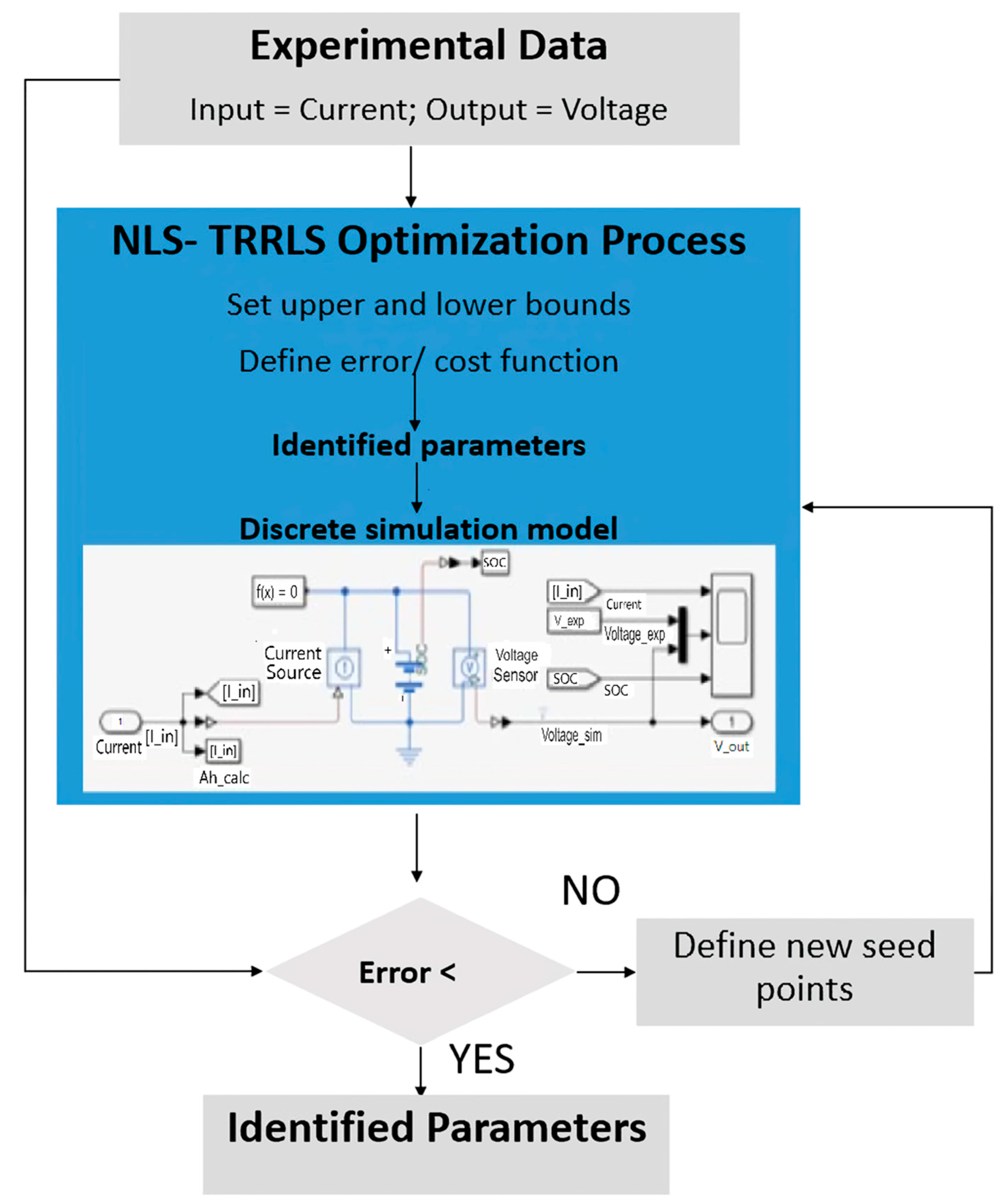
26] across each of the 60 parameters (6 tables × 10 breakpoints) to minimize the sum of squared error. The parameter estimation procedure is described below and summarized in
Figure 3.
Obtain experimental data from the actual cell. In this study, the experiment was conducted by Kollmeyer [
26].
Select the battery model (second-order Thevenin) and build it in Simscape integrated with the MATLAB/Simulink environment.
Load the experimental data into the Simulink model and Parameter Estimator toolbox.
Identify the initial parameter values and simulate the first initial model.
Specify the optimization options. This study used nonlinear least-squares as the optimization method and Trust-Region-Reflective as the optimization algorithm.
Define the cost function (sum square error).
The procedure was run individually at each temperature.
This process produced a set of one-dimensional lookup tables versus SOC for the six parameters at each temperature. Repeating this process at five different temperatures resulted in the lookup table that characterized the cell chemistry under consideration: R0 (SOC, T), R1 (SOC, T), R2 (SOC, T), C1 (SOC, T), C2 (SOC, T), and UOC (SOC, T).
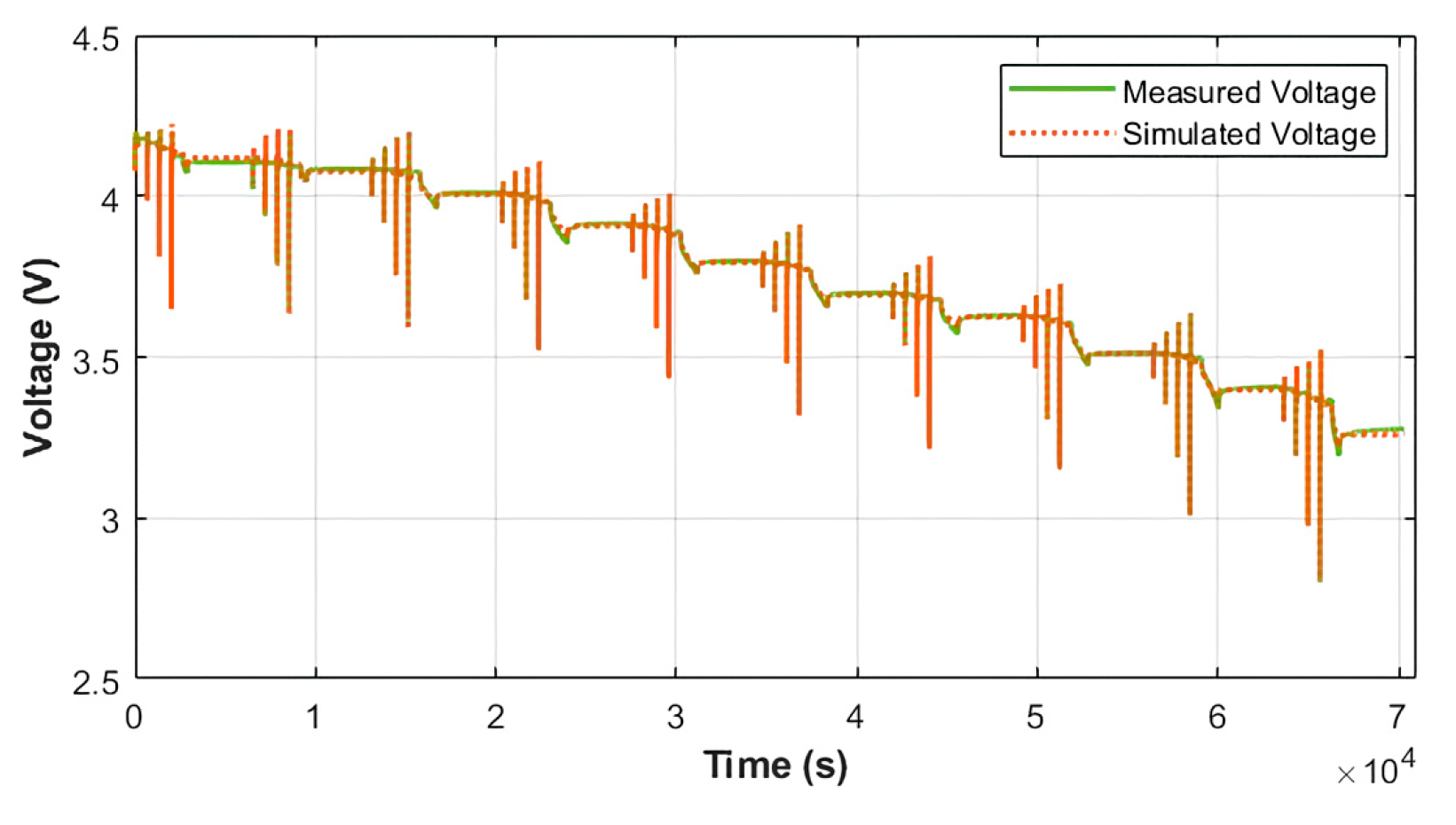
2.3. Identification Results
Figure 4 shows the identification process result at 25 °C. Once the process is completed, the simulated voltage response becomes similar to the measured voltage from the experimental data, indicating that the parameters are well estimated. Similarly, the small error between the simulation and reference is achieved in the parameter identification at −20 °C, −10 °C, 0 °C, and 40 °C.
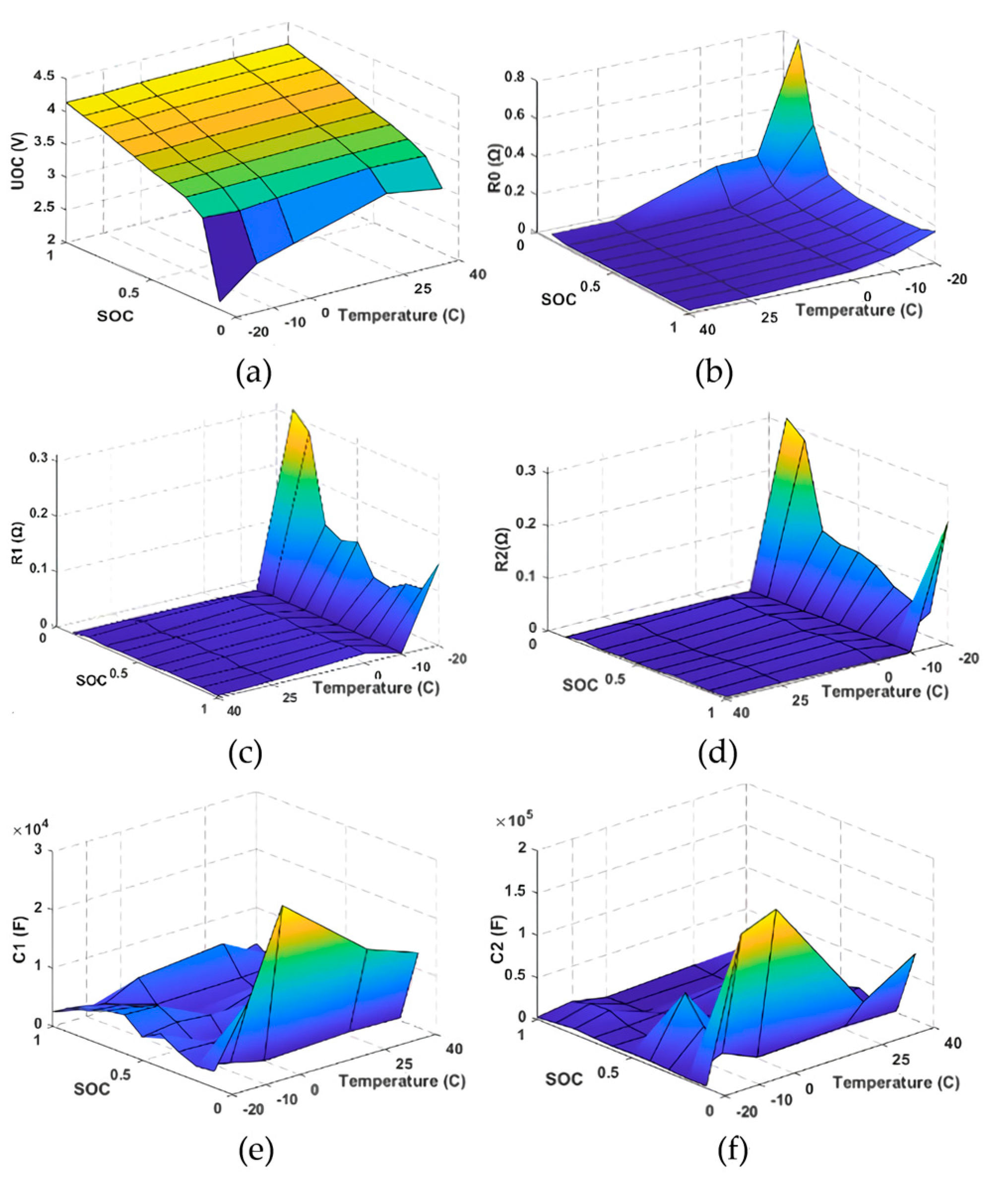
The results of the identified model parameters are shown in
Figure 5.
Figure 5a shows how the voltage source (UOC) is highly dependent on the SOC but is independent of temperature.
Figure 5b describes the evolution of the internal resistance R0. It is easy to see that R0 shows a stronger dependence on temperature than on SOC. At lower temperatures, the resistance is higher. This component energy loss happened due to the ion movement across the separator [
27]. It is also shown that the internal resistance changes with the SOC change at the same temperature. The R0 increases as the SOC decreases. R1 and R2 are the resistive components of the RC networks. The capacitance values C1 and C2 vary to simulate the decay of the voltage.
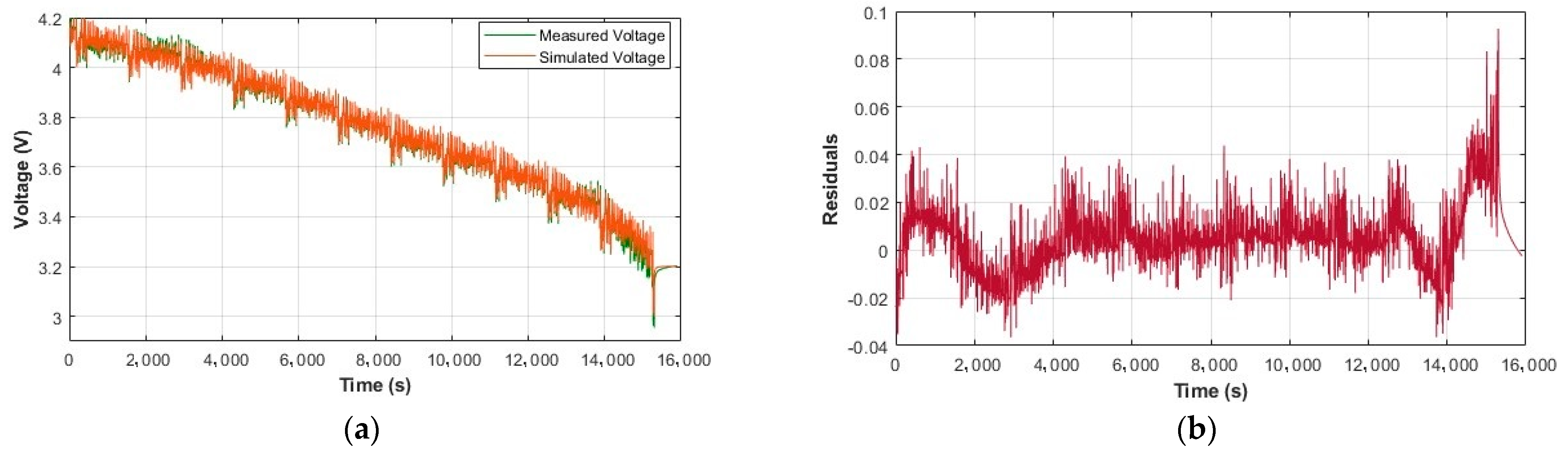
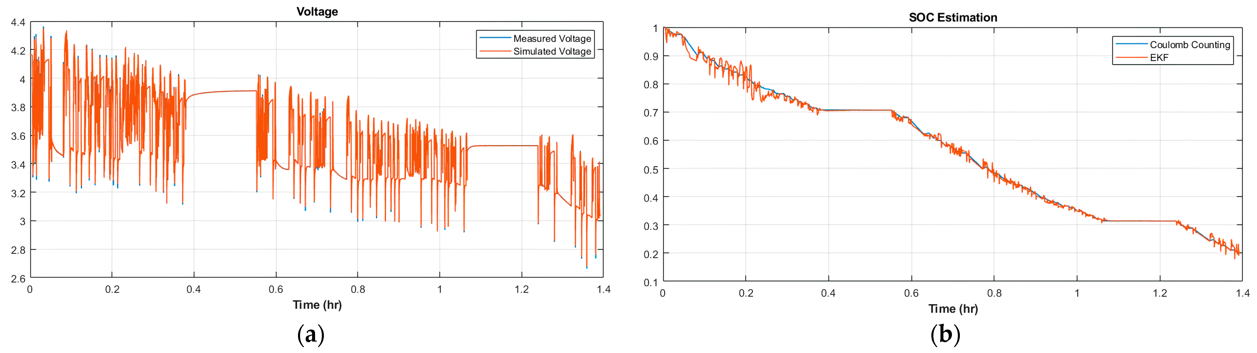
2.4. Model Validation
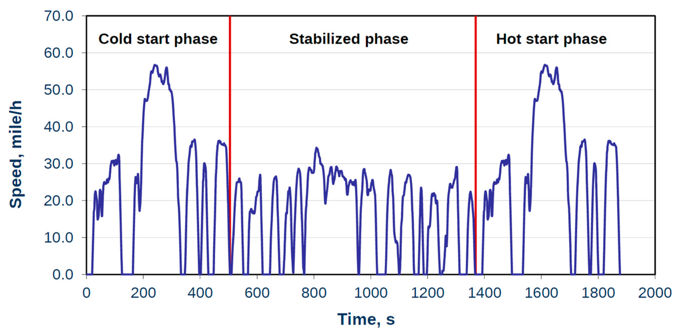
Using the identified parameters, the battery model is validated using a new set of experimental data. This study used the Urban Dynamometer Driving Schedule (UDDS) available in [
25] as the input to compare the actual terminal voltage and simulated voltage. The comparison between the measured voltage and simulated voltage from the proposed battery model is shown in
Figure 6, where the terminal voltage curve of the battery model is consistent with the terminal voltage curve of the reference, and the error fluctuates below ±0.1 V.
3. Battery Pack
The battery cell is the smallest unit of the battery system that powers the EV. The characteristics of a battery cell can significantly affect the overall EV performance. Therefore, choosing a suitable battery type is the first step in building the battery pack. In addition to the various types of cell chemistry, there are also many types of cell shapes. Typical cell shapes for lithium-ion batteries are pouch, cylindrical, and prismatic cells.
Groups of cells wired in series/parallel are called battery modules. The series connection of cells produces a higher total battery voltage, while the parallel connection yields a higher full battery capacity. Then, multiple battery modules are connected in series/parallel to achieve the overall battery system design objectives. The modules are put into a frame to protect the cells from heat and external shocks, with sensors and controllers and the Battery Management System. The battery pack is the final shape of the battery system inside the electric vehicle.
In a series connection, each positive terminal of the battery is connected to the negative terminal of the next one. This configuration will add battery voltages, resulting in a higher system voltage. But the battery capacity remains the same. The parallel structure can be achieved by connecting all the negative terminals of the batteries, as well as the positive terminals. Wiring the cells in parallel will add their capacities, increasing the available runtime for EVs. However, the voltage stays the same.
The battery cell is a fundamental part of the EV battery system. Its characteristics impact EV performance. Choosing the right battery type is the first step. Battery cells come in various chemistries and shapes, like pouch, cylindrical, and prismatic.
Cells grouped in series/parallel form battery modules. A series connection increases the total voltage, while a parallel connection boosts capacity. Modules, housed in a frame with safeguards, sensors, and a management system, constitute the battery pack in an EV.
In series, cells link positive to negative terminals, upping the system voltage. A parallel connection involves joining negative and positive terminals, increasing the runtime. The voltage remains constant.
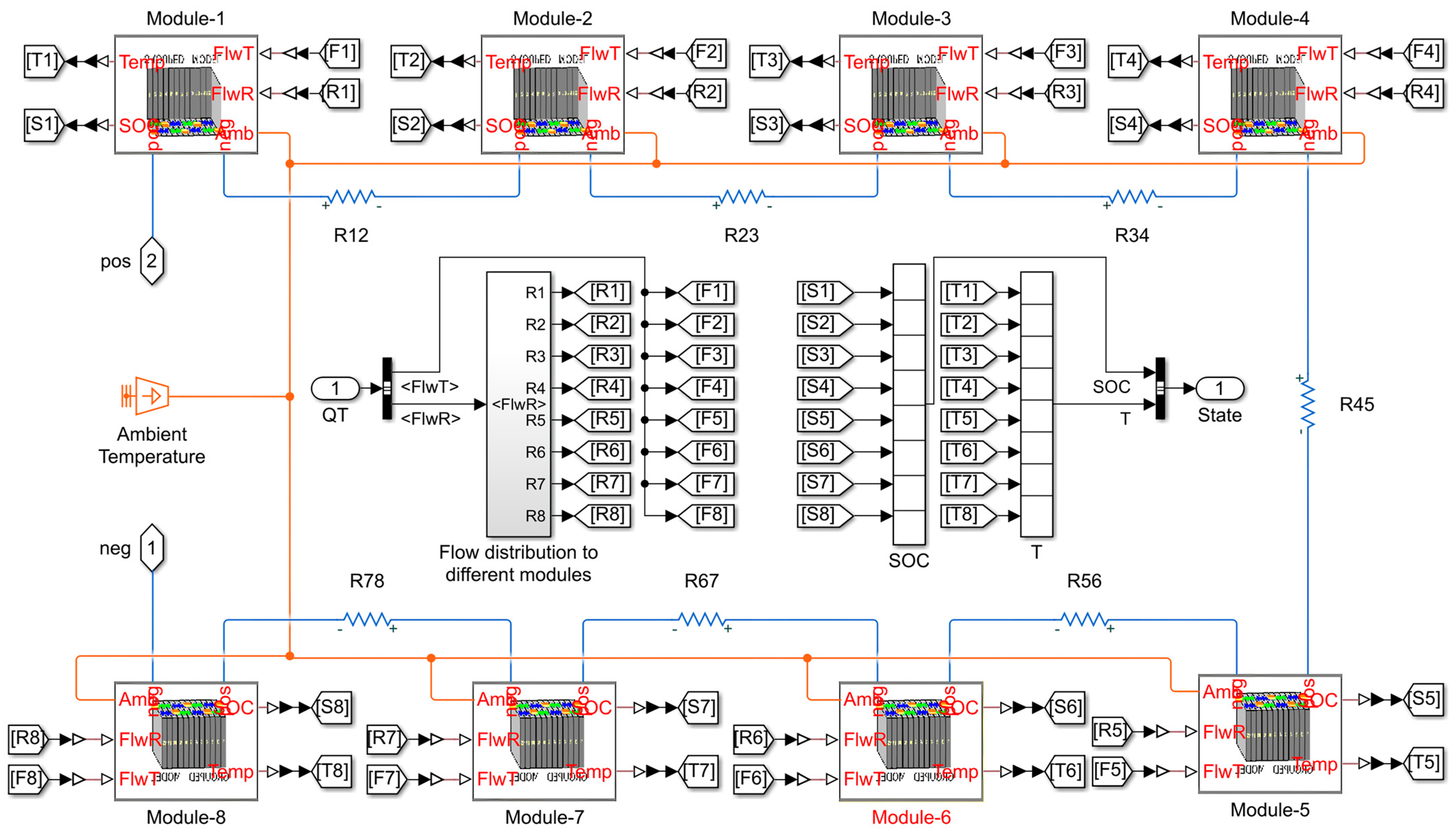
Proposed Battery Pack
The capacity and voltage of a single battery cell are relatively low and insufficient to power an electric vehicle. It is, therefore, necessary to use multiple cells to build up a battery system to achieve the EV total capacity and voltage requirements. The composition of the EV battery system starts with the battery cell, module, and pack. The battery pack proposed in this study comprises eight series-connected modules, illustrated in
Figure 7. The different modules in the battery pack are connected using bus bars modeled as lumped resistors (R12, R23, R34, R45, R56, and R78). To reduce the complexity, 144 battery cells are used. Each module consists of 18 cells with a 3p6s configuration, with three parallel cells per series of six strings. With each ring rated at 3.6 V and 3 Ah/cell, the total pack voltage and capacity are approximately 172.8 V and 9 Ah. Configuration of the battery pack has been shown in
Table 2.
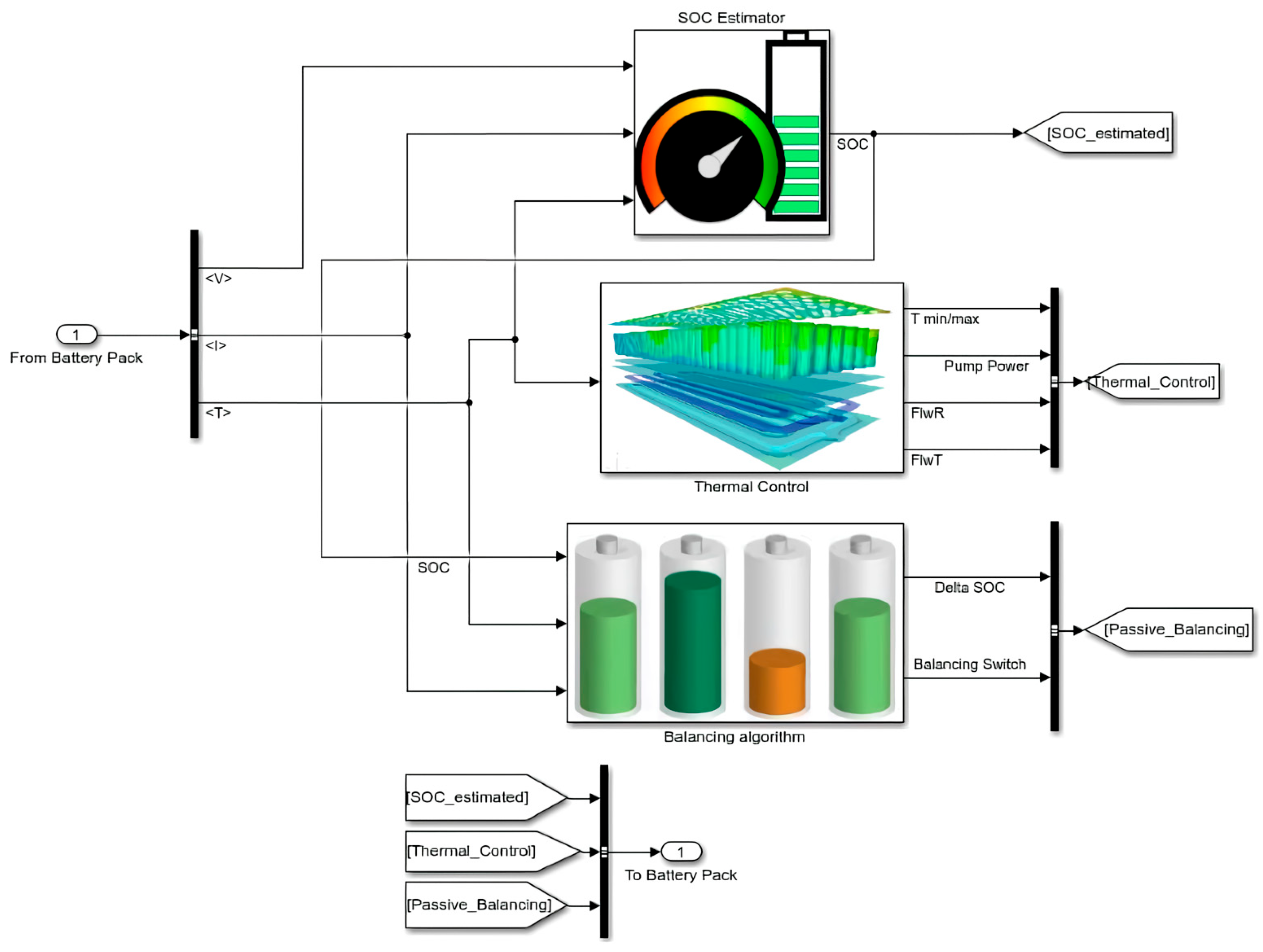
4. Battery Management System
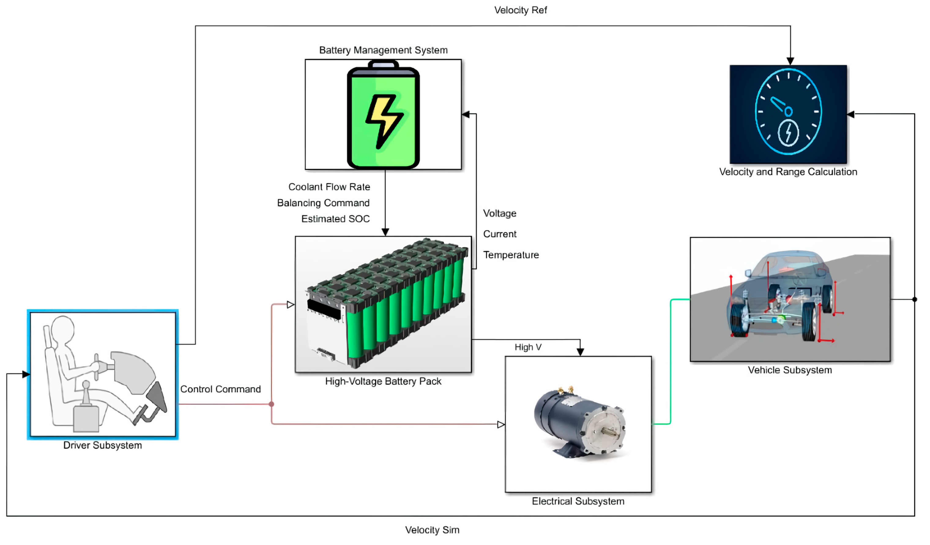
This study proposes to create a battery pack and BMS integrated system for the electric vehicle model. The BMS consists of an SOC estimator, a thermal controller, and a battery pack equalization algorithm, presented in
Figure 8. First, the battery pack sends the measured temperature, voltage, and current to the BMS. The BMS subsystem will return the estimated SOC, coolant flow rate, and balancing command to the battery pack using these measured parameters. The following section will explain the algorithm employed for each BMS task.
4.1. State of Charge Estimation
The state of charge is generally the ratio between the remaining capacities to the battery’s total capacity. Theoretically, it can be obtained by the ampere-hour integration method that integrates the measured battery current as follows:
where
and
are the present and initial state of charge, respectively,
Cr is the maximum available capacity,
η is the cell’s Coulombic efficiency, and
is the load current.
Extended Kalman Filter
The Kalman filter (KF) stands as a renowned theory of estimation, first presented in 1960. This filter offers an iterative resolution employing linear optimal filtration to gauge the state variables of systems. Nonetheless, when dealing with nonlinear systems, a linearization procedure is executed during each stage to approximate the nonlinear system with a linearly time-varying (LTV) system. The application of this LTV system within the KF framework leads to the emergence of an extended Kalman filter (EKF) in the context of an actual nonlinear system [
28].
For a nonlinear system, the discretized process (Equation (4)) and measurement (Equation (5)) models when the noises are considered can be written as follows:
where
is the state vector and
is the system output.
is a dynamic model, and
is the measurement output model.
is the system input.
and
are independent white Gaussian process noise and measurement noise matrices with zero mean and covariance values. The KF algorithm represents a two-step recursive process, prediction, and correction.
The process (Equation (4)) and measurement (Equation (5)) are governed by the nonlinear vector functions and . Therefore, EKF works on the principle of the linearization of the nonlinear function, where the function and are linearized using the Jacobian matrix and first-order Taylor-series expansion, so that inside the equations are the matrixes of partial derivatives (the Jacobian). At the beginning of the EKF, the initial value of state and covariance should be selected. Then, in the prediction part, the system model is used to calculate the prior state estimate and the error covariance, . The correction stages use the priori estimate to calculate the Kalman gain, . Then, the state estimation and covariance matrix are updated.
First, the state space equation of the model (Equations (1) and (2)) is discretized. The transition
and measurement functions
are linearized by using the Taylor series expansion and Jacobian matrices, as explained in [
6]. The discrete time–space form of the practical model after linearization is written in (Equation (6)). As a result, the discretized state equation and observation equation of the equivalent circuit model of the battery can be shown in (Equations (6) and (7)).
The two equations depict the process model and the measurement model, respectively.
where:
, , , , , and , which is the battery ohmic internal resistance.
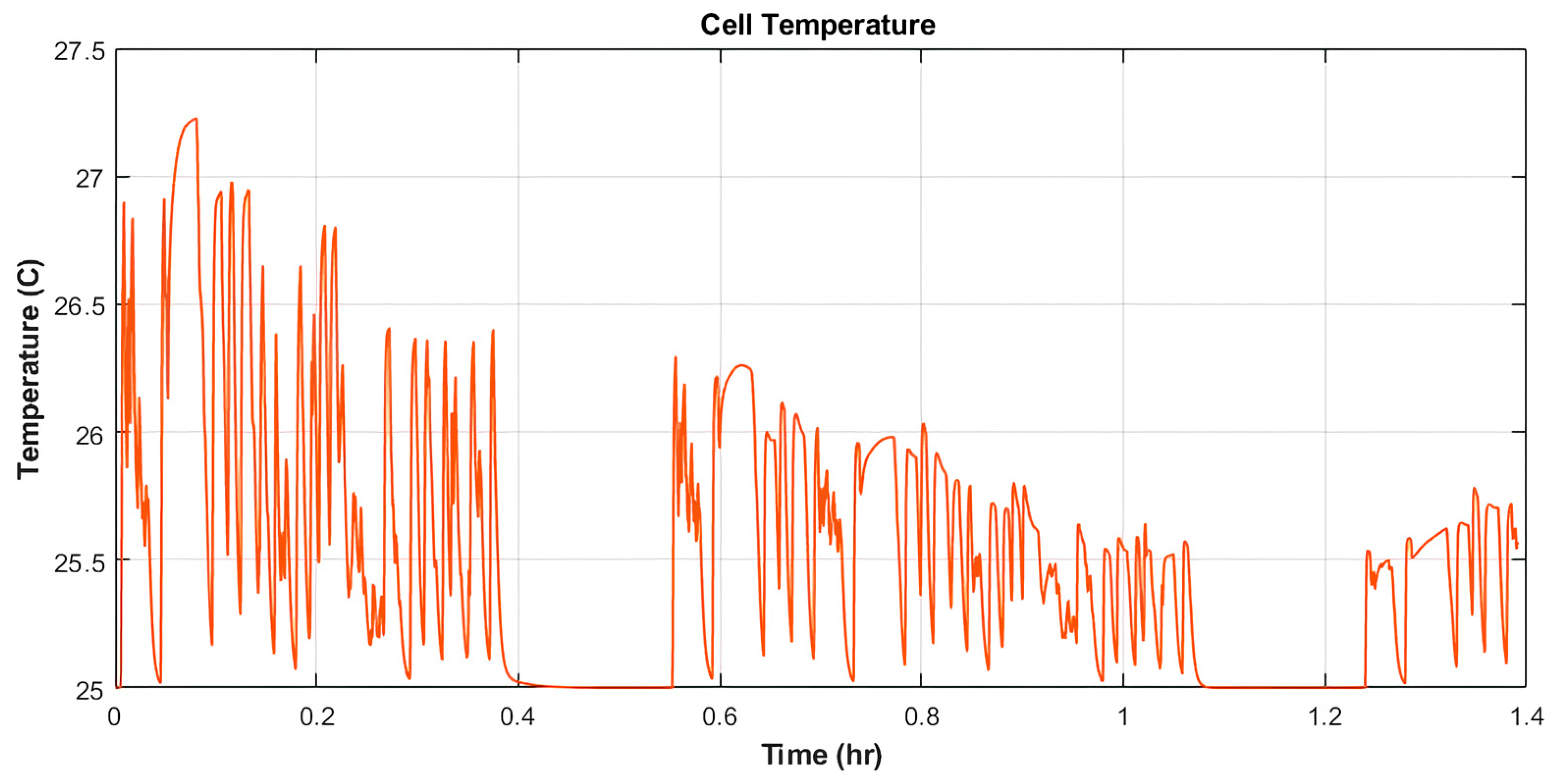
4.2. Battery Pack Coolant Flow Control
The BMS algorithm proposed in this study is not only to estimate the SOC of the battery but also to maintain the battery temperature. The battery pack is built with the Simscape Electrical™ block, and the thermal control is simulated inside the MATLAB/Simulink integrated environment.
The battery module is constructed using a Battery Multi-D Model Block from the Simulink Simscape library. For each module, the thermal management system can be achieved via heat transfer through the four sides of the battery module: right side, left side, top side, and bottom side. In this study, a cooling plate is mounted to the bottom side. Heat transfer of the rest of the battery module sides is set to be convection boundary, which specifies a convection boundary condition on the module face, with its heat transfer coefficient.
To maintain temperature, a coolant control subsystem is added. The subsystem tracks the minimum and maximum temperatures of the battery cell inside the pack. Then, the flow rate is calculated based on the most significant difference between the minimum and maximum cell temperatures in the pack and between the maximum temperature and the temperature of the ambient port. For a difference of 10 degrees Celsius or more, the flow rate is set to 1. When there is no temperature difference between the cell and the battery pack temperature is close to the ambient temperature, the flow rate equals 0. Otherwise, the flow rate is linearly scaled from 0 to 1. The coolant inlet temperature is constant, where the value is 0 degrees Celsius. This subsystem defines the logic to determine the battery pack flow rate with 500 W set to be the maximum pump power consumption. The coolant flow mal distribution occurs in the pack with modules farther away receiving a lesser flow rate.
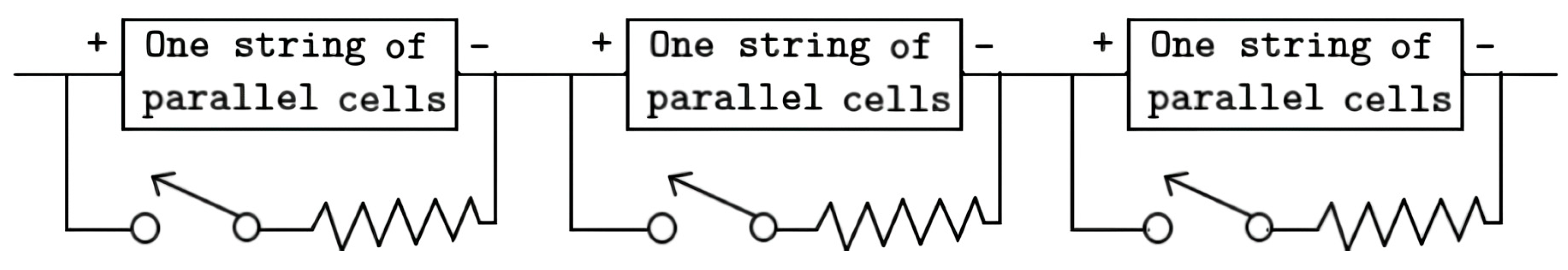
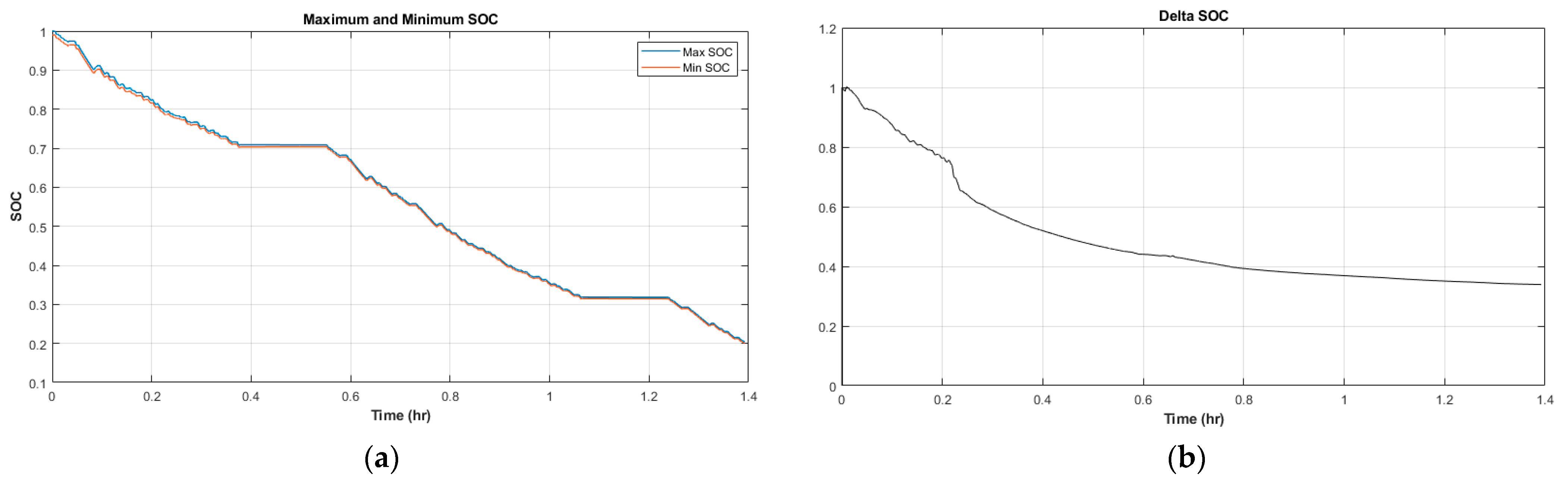
4.3. Passive Cell Balancing
This study proposed a passive cell balancing with a dissipative shunt resistor selected because of its low complexity feature. During passive cell balancing, the energy from the cell with higher voltage and SOC compared to the other cells is dissipated through a combination of a resistor and semiconductor switch. The small resistor and switches are connected parallel to each cell, as shown in
Figure 9.
The BMS controls this parallel current path and allows it to discharge cells with higher SOC in the pack during idle phases. As the excessive energy is dissipated as heat, this balancing method lowers the overall efficiency of the battery system. The selection of a resistor value is limited by the amount of generated heat that the design and the components can handle.
The SOC of all cells is initialized to be 100%, except for the first cell of each battery module. The initial SOC of these cells is set to be 99%, with 1% deviating from the rest of the battery. The parameters and values used for the passive cell balancing system are the shunt resistor (50 Ω), switched closed resistance (0.01 Ω), switch open conductance (1 × 10−8 × 1/Ω), and switch operation threshold (0.5).


