Article

Enhancing Grid Operation with Electric Vehicle Integration in Automatic Generation Control

1
Dipartimento di Elettronica, Informazione e Bioingegneria, Politecnico di Milano, Piazza Leonardo da Vinci, 32, 20133 Milano, Italy
2
US-Pakistan Center for Advanced Studies in Energy, University of Engineering and Technology Peshawar, Peshawar 25000, Pakistan
3
Manager R&D, National Power Control Center, National Transmission and Dispatch Company, Islamabad 44000, Pakistan
*
Author to whom correspondence should be addressed.
Energies 2023, 16(20), 7118; https://doi.org/10.3390/en16207118
Submission received: 14 September 2023 / Revised: 9 October 2023 / Accepted: 12 October 2023 / Published: 17 October 2023
(This article belongs to the Special Issue Smart Electric Vehicle Charging Approaches for Demand Response)

Abstract

:
Wind energy has been recognized as a clean energy source with significant potential for reducing carbon emissions. However, its inherent variability poses substantial challenges for power system operators due to its unpredictable nature. As a result, there is an increased dependence on conventional generation sources to uphold the power system balance, resulting in elevated operational costs and an upsurge in carbon emissions. Hence, an urgent need exists for alternative solutions that can reduce the burden on traditional generating units and optimize the utilization of reserves from non-fossil fuel technologies. Meanwhile, vehicle-to-grid (V2G) technology integration has emerged as a remedial approach to rectify power capacity shortages during grid operations, enhancing stability and reliability. This research focuses on harnessing electric vehicle (EV) storage capacity to compensate for power deficiencies caused by forecasting errors in large-scale wind energy-based power systems. A real-time dynamic power dispatch strategy is developed for the automatic generation control (AGC) system to integrate EVs and utilize their reserves optimally to reduce reliance on conventional power plants and increase system security. The results obtained from this study emphasize the significant prospects associated with the fusion of EVs and traditional power plants, offering a highly effective solution for mitigating real-time power imbalances in large-scale wind energy-based power systems.

1. Introduction

Among other renewable energy technologies, wind energy technology has made significant progress globally, with interconnections to various voltage levels of power systems. However, the inherent intermittency of wind speed makes wind farms stochastic, yielding inaccurate predictions that can cause mismatches between generation and load demand, affecting power system operations and leading to deviations from scheduled values. Power system schedulers use various strategies to balance generation and load throughout the day. However, the uncertainty of wind power often results in an energy imbalance between supply and load demand that necessitates the deployment of additional operational reserves. These reserves are usually provided by conventional power plants, resulting in higher operational costs and increased CO2 emissions [1]. Extensive research on large-scale wind power integration has pertinently increased the use of operating reserves to sustain an active power balance in the system. This emphasizes the influence of wind power’s uncertain behavior on reserve requirements. To optimize the utilization of wind power resources effectively, it is essential to instill flexibility into electric vehicles (EVs), allowing them to actively engage in the demand–supply equilibrium as needed [2,3,4]. The concept of flexibility in the smart grid context has been explained in detail using mathematical models for flexibility [5]. Moreover, real-time flexibility is ensured using peer-to-peer energy trading. Implementing superior coordination control strategies is vital for the optimal utilization of EVs, leading to substantial reductions in operating costs and carbon emissions [6,7,8].

1.1. Related Work

Over the past decade, extensive research has focused on the vehicle-to-grid (V2G) technology of EVs, driven by their significant potential to provide grid ancillary services actively [6,7,8,9,10,11,12,13]. By adopting the V2G mode, EVs can operate as battery storage systems, enabling bi-directional power flow with the power grid. This enhanced capability supports grid flexibility and resilience, paving the way for more efficient energy utilization and demand response management. EVs are not confined to a single location but are dispersed across regions and utilized for commuting or long-distance travel [9]. A study indicated that the average roundtrip driving distance in the U.S. is approximately 50 km, with an average driving time of ~52 min, although there is significant variability. A survey of U.S. drivers nationwide reveals that 60% of commuters travel distances less than 80 km [9]. Importantly, EVs employed for daily commuting remain idle for approximately 22 h per day, accumulating surplus energy stored in their batteries during travel. This excess energy presents an opportunity to support the grid and can be used to recharge EV batteries. Over the past decade, extensive research has explored the contribution of EVs to secondary frequency response and conceptually frame worked the EVs integration into bulk power systems, considering technical grid operation and the electricity market [9,10,11]. The challenges and benefits of the proposed integrated framework have been examined, focusing on mitigating anticipated errors. Regarding distributed system management, energy communities’ growth driven by cheaper storage and economy-driven energy exchange has been explored [12,13]. Further, novel transactive control frameworks were introduced, optimizing energy scheduling between prosumers and storage providers and offering two game-theory-based algorithms adaptable to grid communication.
Meanwhile, the system response has been thoroughly analyzed at the inertial and primary control levels [14,15], employing a finely tuned adaptive mechanism to ensure utmost system reliability even under arduous conditions. Hence, the efficient harnessing of EVs’ capabilities for grid regulation holds great potential for significantly augmenting the proportion of renewable energy in future power systems. Giordano et al. [16] investigated the impact of increasing EVs on grids, focusing on aggregator-led scheduling for grid stability. They proposed automated logic for day-ahead EV fleet charging, maintaining grid balance, and successfully testing it on three EVs without grid disruption. Diaz-Londono et al. [17] proposed two optimal strategies; one focused on lower energy prices and the other on providing flexible grid capacity, aimed at integrating EVs efficiently and avoiding transformer overloads. Moreover, the same group discussed how evolving energy practices impact power grid regulations and the role of aggregators in connecting flexible loads, like EVs, to the grid [18]. Based on a financial perspective and methodology, the benefits for aggregators and end-users were assessed, highlighting scenarios where aggregation is advantageous, and revealing potential conflicts of interest, with numerical results demonstrating varied consumer benefits and situations where intermediaries may not be beneficial.
Mignoni et al. [19] presented a novel control strategy for optimizing the scheduling of an energy community comprising prosumers with unidirectional V1G and V2B capabilities. Long-term parked EVs served as temporary storage systems for prosumers, while prosumers offered V1G services to EVs at charging stations. To handle the framework’s stochastic nature, EVs shared their parking and recharging time distributions with prosumers, enhancing energy allocation. Prosumers and EVs, acting as self-interested agents, engage in a rolling horizon control framework to reach operating strategy agreements, framed as a generalized Nash equilibrium problem solved in a distributed manner. Meanwhile, Hosseini et al. [20] present a resilient, decentralized charging approach for extensive EV fleets, aiming to reduce energy expenses and battery degradation while addressing fluctuations in power costs and inelastic loads. A robust optimization based on uncertainty sets formulated the challenge as a manageable quadratic programming problem with restrictions on grid resource sharing. The practicality of utilizing a commercially available EV to offer grid flexibility in real distribution networks has been examined [21]. More specifically, the employed controller who adheres to IEC 61851 and SAE J1772 standards [22] and a Nissan Leaf was assessed in a Danish distribution grid to deliver congestion management, voltage support, and frequency regulation. Performance metrics, including EV response time and precision, were appraised to validate smart grid concepts using standard-compliant equipment. EVs provide frequency regulation services in renewable energy-rich power systems [23], employing a leader–follower game between EVs and their aggregator to optimize charging and regulation scheduling while addressing signal uncertainty. The aggregator incentivizes EV participation through pricing, and EVs aim to balance consumption costs and regulation revenues. Moreover, Tushar et al. [24] discuss the importance of microgrid technology and integrating electric vehicles, energy storage, and renewables for efficient electricity management. They introduce a real-time decentralized demand side management system that optimizes residential electricity consumption and improves microgrid planning for enhanced power delivery quality.
While a substantial body of literature has addressed EVs integration challenges, it is imperative to note that significant considerations and gaps persist, awaiting further exploration and resolution. For instance, a closed-loop control methodology implemented in the context of EV participation in the AGC system [25] accomplished bidirectional power flow for charging and frequency regulation. However, the study’s assumed time delay of 1–2 s contrasts with actual turbine and EV responses, which suggests a longer delay time of 7–8 s. Moreover, a robust frequency regulator was devised for a power grid comprising multiple interconnected regions, considering EVs involvement in load frequency control services, thus enhancing the resilience of Automatic Generation Control (AGC) services [26]. However, this study lacked consideration for practical constraints, such as higher time delays and dead bands, and did not thoroughly assess realistic EV capacity. Meanwhile, Sanki et al. [27] integrated plug-in EV services into the AGC system to tackle the grid stability challenges of integrating highly intermittent solar and wind technologies into grid operations. Khezri et al. [28] incorporated EVs in the AGC regulation process utilizing a consolidated model of EVs governed by a fractional order-PID controller to manage the discharging state of EVs. However, this study omitted the EV contribution over 24 h when assessing EV availability from the consumer side. Therefore, the responsive involvement of the EVs in AGC necessitates a more thorough examination of extensive power grid models. This requires careful consideration of practical constraints, including delays, parametric uncertainties, and dead bands. The approach used in this study will offer valuable perspectives into the dynamic performance of EVs and their influence on grid stability, ultimately contributing to establishing more resilient and reliable AGC-based power systems.

1.2. Our Contributions

This study investigates utilizing the storage capabilities of EVs to reinforce future power systems, particularly in controlling operations involving massive wind power integration. The primary aim is to create a simple yet sturdy and responsive AGC system for a real power system network to regulate the system frequency efficiently and cost-effectively. By effectively combining the capacities of EVs with thermal energy systems (TES), the AGC model offers improved active power regulation services. The developed model introduces an enhanced allocation of regulating reserves from EVs while considering their power threshold levels. The dispatch strategy formulated for the AGC system prioritizes the utilization of reserves from EVs over those from TESs in grid balancing procedures. Integrating EVs ensures greater flexibility, cost-effectiveness, and reduced environmental strain, leading to a more resilient and eco-friendly energy landscape. Moreover, the Dig SILENT Power Factory software (2019 SP3) assesses the proposed AGC dispatch strategy. The proposed model integrates detailed models of various generating units, including wind energy systems (WES), TES, gas turbine energy systems (GTES), and an electric vehicle area (EVA). Additionally, a specific windy day in 2023 was chosen to study and analyze forecasting errors in a large-scale wind energy-based power system network.
The primary contributions of this research are as follows:
  • A comprehensive power system model has been developed, incorporating key generating units like TES, GTES, and WES. Furthermore, a comprehensive EVA model is developed, harnessing frequency control capabilities utilizing the concepts of positive and negative regulation capacities.
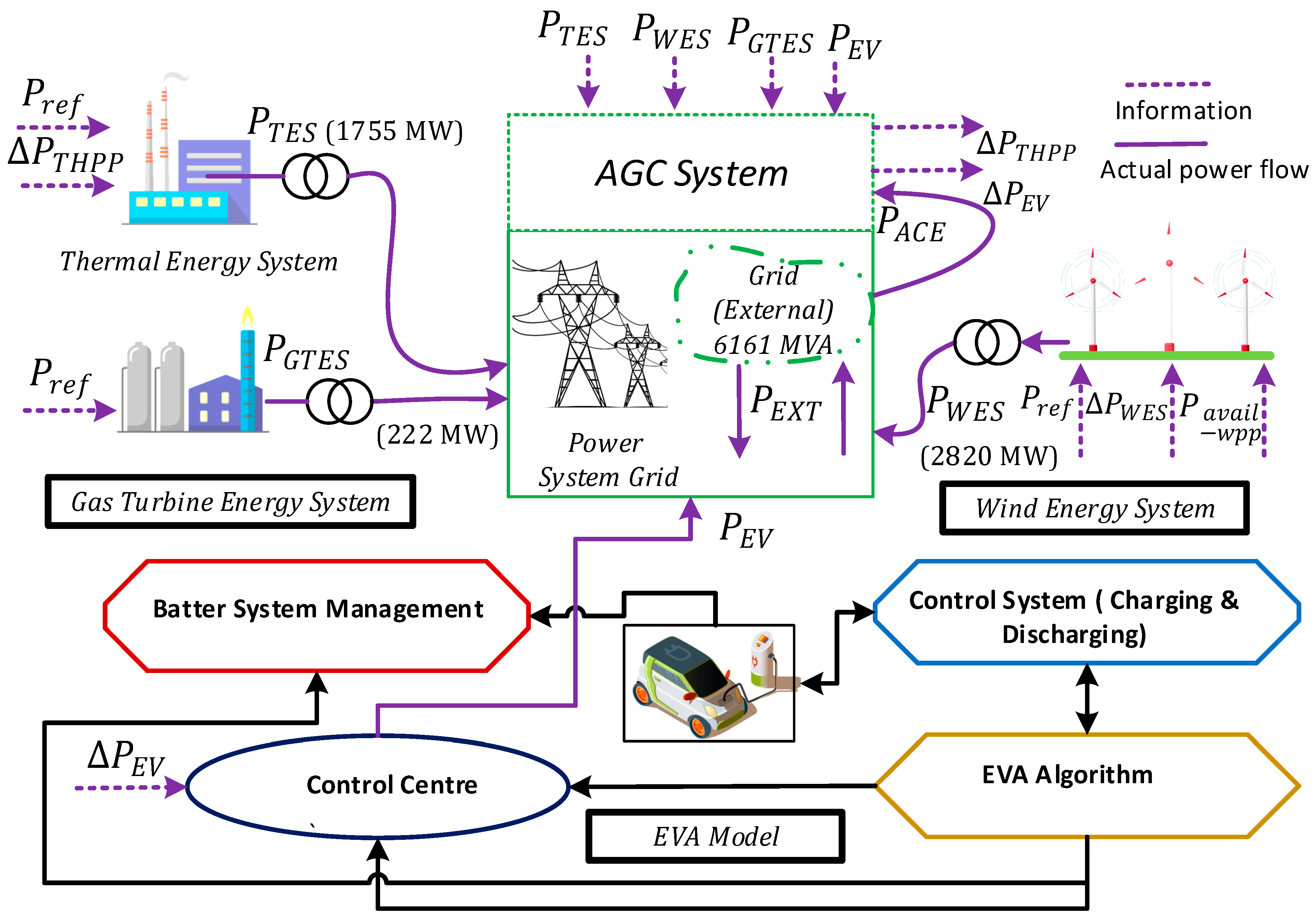
  • A centralized AGC model for the proposed power system is developed to facilitate secondary frequency response and ensure power balancing operations.
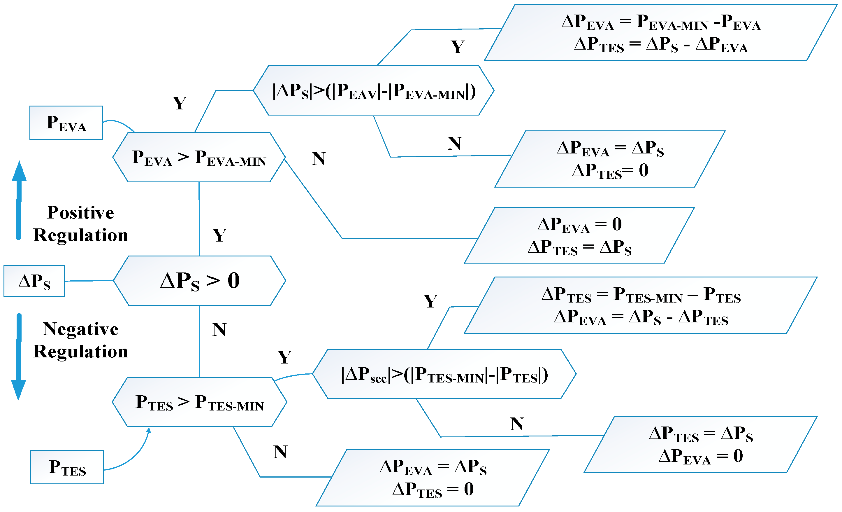
  • A real-time dynamic dispatch strategy is formulated for the AGC model to efficiently integrate reserve capacities from the EVA model and prioritize its utilization over TES.

1.3. Paper Outline

This paper is structured systematically, with Section 2 focusing on the detailed modeling of TES, GTES, WES, and the EVA model. In Section 3, the AGC system modeling is outlined, incorporating the model of the power plant units and EVA system. Section 4 delineates the proposed power dispatch approach and validates its performance. Section 5 concludes the paper, drawing insightful conclusions from the investigation and providing future recommendations.

2. Generating Units and EVA Modelling

This section comprehensively overviews EVs’ modeling process and various power plant units, such as TES, GTES, and WES. Governors are accurately engineered and strategically positioned on each generating unit to ensure a highly efficient primary frequency response. Their vital role is effectively regulating and stabilizing the system’s power output. Additionally, we developed a sophisticated EVA model that plays a key role in this integrated system. The EVA model receives dispatch orders from the AGC system and employs an advanced inbuilt algorithm to efficiently route the instructions to individual EVs. This intelligent routing system ensures that the required secondary regulating reserves are promptly provided, contributing to the overall grid stability and efficient energy management.

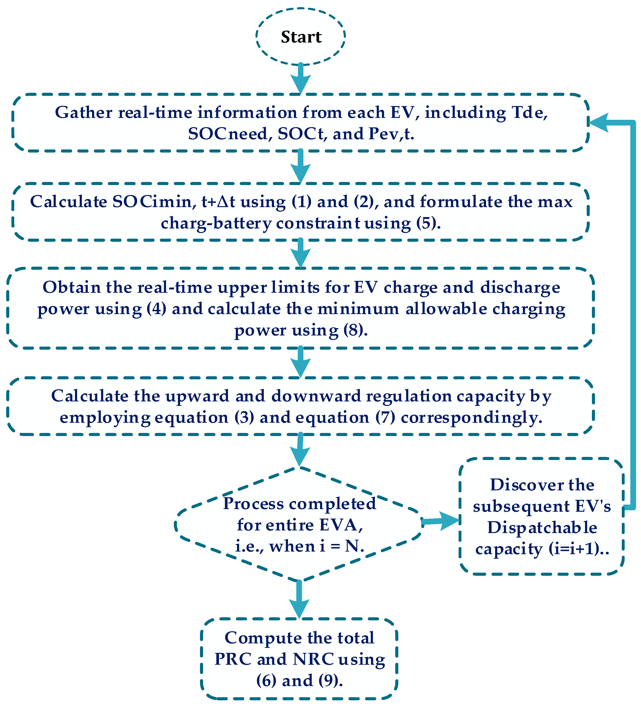
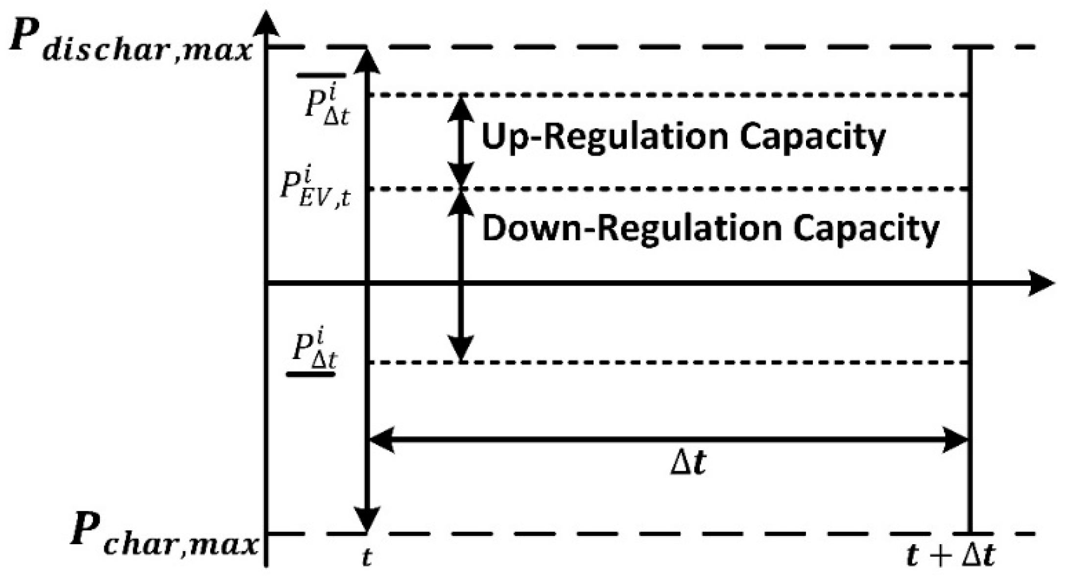
2.1. EVA Modelling for Grid Support

The integration of EVs offers substantial potential in effectively managing the system frequency and maintaining a harmonious equilibrium between demand and generation. This is accomplished by employing the EVs as both load and source, controllable by the AGC regulator. The AGC controller is crucial in supporting grid operations, as it promptly responds to any fluctuations in the system frequency. An EVA designates a specific zone where many EVs are assembled and overseen by a dedicated control center. These EVAs are entrusted with dispatch orders from the AGC and utilize an intrinsic algorithm, illustrated in Figure 1, to allocate the orders to individual EVs. The algorithm functions in actual time, perpetually calculating the controlling capability of EVAs for the existing dispatch interval. Consequently, the aggregator must comprehend each EV condition and conduct during this duration.
This research proposes a novel EVA model designed specifically for the AGC system. The formulation of the model follows a first-order transfer function, incorporating two pivotal parameters: frequency gain ( K E V ) and the time constant for charging and discharging ( T E V ). To attain maximum precision and pragmatic feasibility, we carefully integrated the inherent time lag reaction of the EVA model into the AGC system, covering a span of 0 to 3 s. This time delay encompasses two critical factors significantly influencing the overall system dynamics. The first is the duration for the aggregator to transmit the received orders to individual EVs within the system. This step introduces a certain degree of time delay in the overall response. The second factor contributing to the time delay is the inherent latency arising from communication channels, typically on the order of milliseconds. By acknowledging these time delay elements, we aims to construct a model that closely emulates real-world conditions. Our study delves into analyzing the response of EVs in the AGC system at the power system level, considering various important aspects, such as the time delay, dead band, and dynamic response characteristics. This comprehensive analysis provides valuable insights into the functioning and performance of the AGC system in conjunction with the proposed EVA model.
The EVA model provides positive regulation capacity (PRC) during positive imbalances in the system and negative regulation capacity (NRC) during negative imbalances. We consider a group of 17,000 EVs, each with an average battery capacity of 60 KWh ( C i ) . The installed inverters have an average capacity of 7.5 KW. Consequently, the cumulative peak power accessible for regulation intentions is ±127.5 MW. Figure 2 illustrates the calculations for PRC and NRC. In the case of a single EV, within a specific time interval ∆t, PRC can be defined as the discrepancy between the present charging power ( P E V , t i < 0 ) and the maximum discharging power ( P t i > 0 ). Conversely, NRC is determined by the difference between the current discharging power ( P E V , t i > 0 ) and the maximum charging power ( P t i < 0 ). To execute the PRC process, the loads linked to EVs are restricted, or the accumulated energy in their batteries is transmitted back to the grid using sophisticated V2G technology. In contrast, the EVs’ power demand is augmented for NRC operation to facilitate power absorption from the grid to charge their batteries. The role of the aggregator is paramount in efficiently managing the collective operation of all EVs, seamlessly orchestrating their contributions during specific time intervals, thereby ensuring a highly effective and harmonized regulation response.

Regulation Capacities

Determining PRC and NRC entails a scrupulous procedure, as depicted in Figure 2, where specific parameters are carefully measured. Subsequently, precise calculations are carried out for each dispatch interval to accurately evaluate the PRC and NRC. The realization of the PRC operation entails two key methods: mitigating the load effect or facilitating the transfer of EV battery stored power back to the grid through precise controls. For PRC computation, this study incorporates two important constraints. First, the current state of charge (SoC) represented as ( S o C t i ) must align with the user’s specific requirements S o C n e e d i . It is employed for regulation purposes at time ( t + Δ t ) as formulated in (1):
S o C m i n ,   t + t i       S o C n e e d i P c h a r g ,   m a x × η × T d e p ,   i t + t C i
where η represents the coefficient signifying the battery’s discharge and charge effectiveness, Ci indicates the battery’s capability, and T d e p ,   i   specifies the time of departure for the ith electric vehicle.
The second constraint pertains to battery deterioration, predominantly induced by charge cycles. Consequently, to balance achieving sufficient regulatory capacity and safeguarding battery health, careful attention is paid to the depth of discharge. This research establishes a limit of 60% for the depth of discharge (DoD) power, ensuring that the battery operates within a controlled DoD, mitigating the detrimental effects of excessive cycling while providing the necessary regulatory capacity.
S o C m i n ,   t + t i   40
Figure 2 depicts the charging or discharging power of EVs that can be precisely adjusted or increased within a specified Δt when P t i surpasses P E V , t i . This observation highlights the ability to enhance the PRC of each EV for the interval Δt, enabling an active contribution to grid stabilization and power regulation. The PRC of an EV within Δt is determined by considering the dynamic interrelationship between the EV’s charging or discharging power and its maximum available discharging power. This calculation effectively quantifies the capacity of each EV to participate in the positive regulation process, optimizing the overall power management system.
P P R C i = P t i P E V , t i
Here ,   P t i = min (   P c h a r g , m a x ,   ( S o C t i × C i   ) t × η )     if   S o C t i > 0 max (   P d i c h a r g , m a x ,   ( S o C t i × C i   ) t × η )    i f   S o C t i < 0
where P P R C i represents the PRC capacity of the ith vehicle, and the variation in SoC represented as S o C t i indicates the potential for increasing the maximum capacity of the EVs within Δt.
  S o C t t = S o C E V , m i n ,   t + t i S o C E V , t i
Derived from this, the entire PRC of EVAs can be computed in the following manner:
P P R C ( t o t a l ) i = i = 1 N P P R C i
Analogously, the charge or discharge rate of EVs can be curtailed for a specific time interval Δt when P t i surpasses P t i as shown in Figure 2. By implementing this measure, the NRC of each EV for the time interval Δt can be effectively ascertained. The NRC capacity of an EV during Δt is determined through a comprehensive assessment of its charging or discharging power in comparison to the maximum available discharging power.
P N R C i = ( P E V , t i P t i )
P t i = min   ( P c h a r g ,   m a x ,   ( S o C t i × C i   ) t × e f f )
where P N R C i represents the ith vehicle participating in the negative regulation capacity. Given this premise, the cumulative NRC of EVA can be computed as follows:
P N R C t o t a l i = i = 1 N P N R C i
In this context, it is essential to note that the constraints governing NRCs primarily revolve around the SoC and the maximum charging power of the charger.
S o C m i n ,   t + t i   100 %

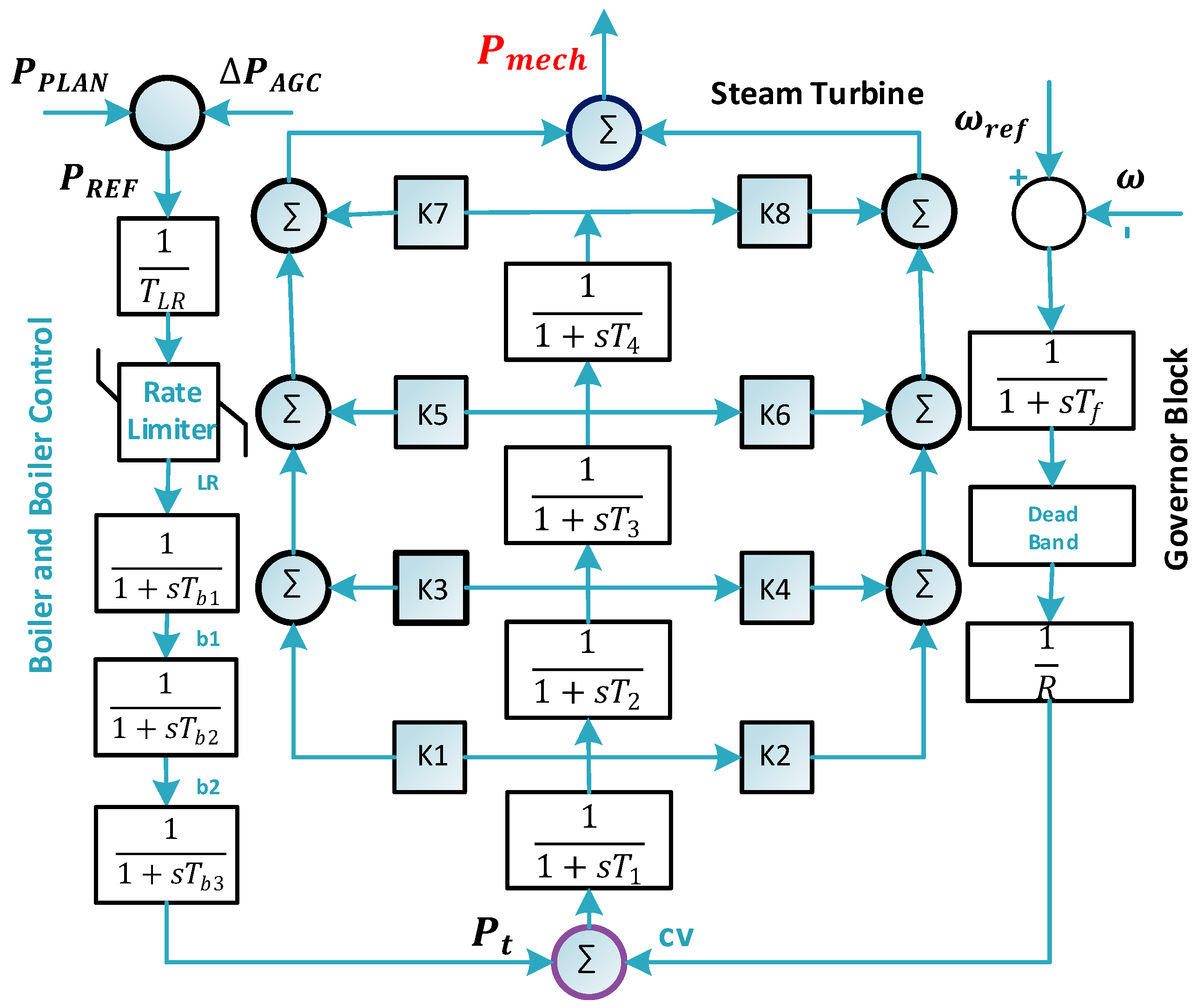
2.2. Modelling of the Thermal Energy System (TES)

This research extensively analyses the aggregated TES model concerning active power balancing control. A particular emphasis is placed on the boiler response time, a crucial parameter affecting the overall plant’s reaction and system stability. The TES model, depicted in Figure 3, is derived from previously described models [29,30]. The TES model underwent simplification to facilitate long-term dynamic simulations. Two essential inputs, main steam pressure ( P t ) from the boiler and control block, and the control valve (cv) from the governor block, determine the mechanical output power ( P m e c h ) of the steam turbine block. When load fluctuations ( L R ) arise, the boiler model quickly computes the suitable ( P t ) value to offset the load changes, considering the turbine’s output limitations and steam energy storage delays.
This all-encompassing approach guarantees superior precision and dependability in the dynamic simulation studies of the TPS model. The L R signal assumes a pivotal role, functioning as a forward signal to the boiler and a controller for the turbine valve. The model combines the influence of steam temperature regulation and generator reference current for accuracy and steadiness. The ramp-rate limit is maintained at 30 MW/min for a controlled response. The time lags ( T b 1 , T b 2 ,   a n d   T b 3 ) in the boiler model profoundly affect frequency and power time reactions. The boiler response severely affects the overall turbine response, taking about 5 to 6 min to settle. The power-to-mechanical conversion relies on the boiler model’s response ( P t ) and the governor’s output (cv), contributing to system dynamic behavior and stability. The steam turbine’s response depends on four-time constants ( T 1 , T 2 , T 3 , and T 4 ) representing different volumes. Coefficients ( K 1 K 8 ) determine power contributions from turbine sections. The speed governor regulates the turbine’s speed valve, considering generator speed and droop settings as inputs for primary frequency response, ensuring stability with a dead zone to prevent unnecessary adjustments.

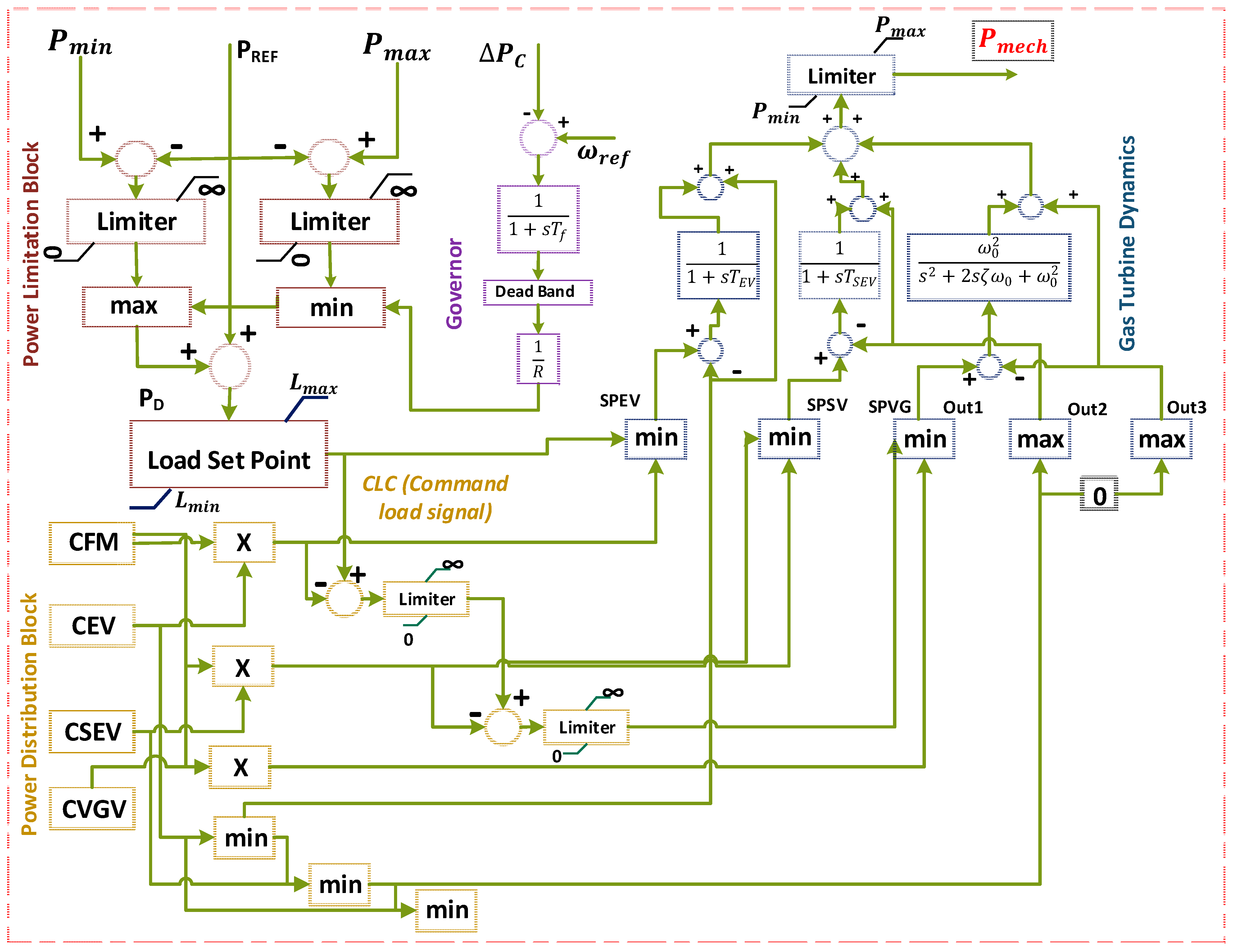
2.3. Modelling of Gas Turbine Energy System (GTES)

A detailed GTES model was developed (Figure 4). The GTES is the primary response source, achieved through the governor linked to the generator’s turbine. The GTES governor incorporates a dead band and a low-pass filter, showcasing droop characteristics. The dead band ensures stability by disregarding low-frequency deviations, while the low-pass filter stabilizes rotor speed against high-frequency deviations, further promoting system stability. Any power deviation beyond the dead band’s limits leads to frequency deviations, which activates the droop characteristic signal, ultimately generating a power demand signal ( P c ) . This signal drives the necessary adjustments in the power generation process, allowing the GTES to promptly and effectively respond to power fluctuations within the system. The P c signal holds utmost significance in the functioning of the GTES, which includes the power limitation block (PLB), power distribution block (PDB), and gas turbine dynamics block (GTDB) (Figure 4). The PLB imposes physical constraints on the turbine’s response, enforcing upper and lower power level restrictions ( P m a x and P m i n ) based on combustion technology limitations. To comply with combustion constraints, the set points L m a x and L m i n   act as maximum and minimum load limits. Additionally, a rate limiter block carefully regulates the rate of change for the P c   signal to optimize gas turbine performance while ramping up and down processes. The PLB produces a CLC signal that acts as an input to the PDB. Two sequential combustion chambers are included in the PDB block that skillfully blend compressed air with fuel to initiate efficient combustion processes. Initially, the environment incineration chamber receives compressed air, subjecting it to warming, and deftly blends it with 50% of the overall fuel. Subsequently, the mixture is forcibly expelled through a high-pressure turbine, provoking its rapid rotation. The resultant mixture is directed into the SEV chamber. Here, an additional 50% of the distributed gasoline is intricately amalgamated with a measured quantity of supplementary air, guaranteeing an optimal combustion process.
The setup includes a low-pressure turbine with operational adaptability, low emissions, and high efficacy. Power contribution coefficients such as CVGV, CFM, CEV, and CSEV are precisely adjusted to mirror system traits. The capabilities of the combustors, air compressor, and CLC signal from the power limitation block determine the output variables SPEV, SPSV, and SPVG. The configuration ensures optimal performance and environmental consciousness. The sophisticated interaction of factors significantly influences power generation, providing resource optimization. Gas turbine dynamics are closely linked with compressor and combustor dynamics. First-order leg functions elegantly represent the environment and sequential environment combustor dynamics, while second-order functions aptly describe VIGV dynamics. The mechanical power output ( P m e c h ) of the GTES relies on CFM, CEV, CSEV, CVGV, and CLC, ensuring optimal performance within the specified limits. The GTES exhibits a response time of 30 to 40 s when subjected to a step change in input power, primarily due to turbine ramp rates impacting its overall response time.

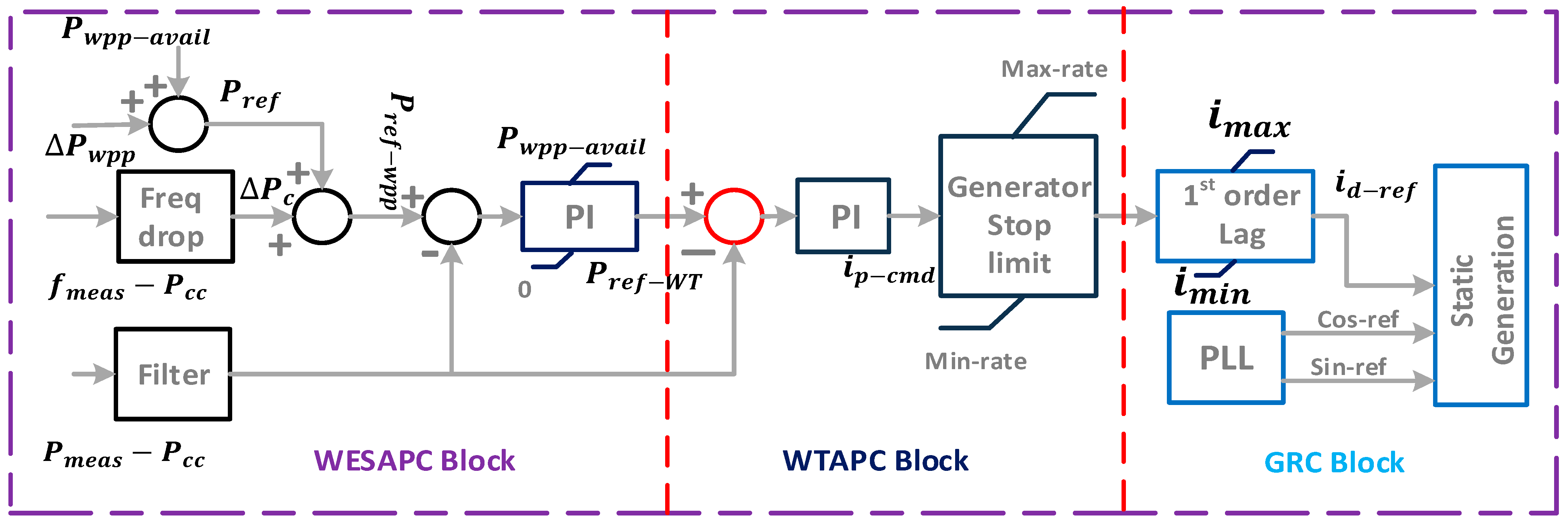
2.4. Modelling of Wind Energy System (WES)

Figure 5 provides a comprehensive investigation into the dynamic behavior of WES and its capacity to contribute to grid balancing through active power control. WES emphasizes the overall performance of aggregated wind energy systems (WESs) within the power system. The WES model is expertly streamlined and tailored for active power regulation and long-term dynamic simulation studies [7]. WES comprises essential blocks, such as wind turbine active power controller (WTAPC), WES active power controller (WESAPC), and generator reference current block. The frequency droop block is crucial in providing primary frequency response ( P c ) contingent on available wind power and systemic frequency droop parameters. This intricate relationship ensures the power plant responds actively and effectively, maintaining grid stability and balance through active power control. The efficacy of this reaction is contingent upon the magnitude of wind power accessible ( P W E S a v a i l ) and the intricacies of the power system’s frequency droop parameters, amplifying the plant’s dynamic interplay with the power grid.
When the reference power ( P r e f _ W E S ) of the WES is modified, the WESAPC block swiftly generates a novel turbine allusion power P r e f _ W T . The calculation for P r e f _ W E S within the WESAPC block is reliant on the allusion power P r e f , the prime frequency response signal P c , and the gauged power at the point of shared coupling P m e a s _ P C C . The PI regulator in the WESAPC block maintains the regulation of the allusion power signal for the WTAPC block. This regulation is established through an error comparison between P r e f _ W P P and P m e a s _ P C C . To avert extra power output, the available power signal P W E S a v a i l is employed to restrict the PI regulator’s output. Meanwhile, the WTAPC block generates the current active component ( I P c m d ) of the generator as its output, calculated by the PI regulator within the WTAPC block. This calculation relies on the discrepancy arising between the wind turbine reference power P r e f _ W T and P m e a s _ P C C . The investigation involves the intelligent development of the wind turbine’s generator type IV model, which confers unmatched operational flexibility compared to other generator models. This advanced design significantly boosts the wind turbine’s performance and adaptability in various operational situations, rendering it a beneficial option for wind power plants. The wind turbines are equipped with distinct machine-side and grid-side inverters, operating autonomously. The machine-side converter facilitates seamless generator rotation at the optimal rotor speed, while the grid-side converter independently regulates the flow of active and reactive power. The wind turbine generator is a static generator utilizing the model based on the current sources technology. The reference current and input from the phase-locked loop determine the dynamic response of the stationary generator. Controlled operation is ensured by limiting the ramp rate of the available wind power. The WES showcases a remarkable response time, swiftly adapting to fluctuations in system load within 2 to 4 s.

3. AGC Modelling

An effective, reliable, and consistent electricity supply within a cohesive power grid is achieved through AGC, which continuously monitors load oscillations and adapts generator output accordingly. The efficient operation of the AGC service requires continuous monitoring of frequency fluctuations to establish the area control error (ACE). The essential step in AGC control involves P A C E , i   as expressed in (11):
P A C E , i = j   ϵ   A n β i Δ f + ( P i j S c h P i j A c t )
where P A C E , i signifies the total discrepancy, and P i j S c h and  P i j A c t represent the prearranged and real data flows in the line; the difference between these is represented by P t i e . In this context, the parameter β i takes on significance as it embodies the frequency bias constant specific to the ith area. Its computation involves the ratio D i + 1 R i . Notably, Δf symbolizes the frequency deviation from the present value, making it a crucial indicator in AGC operations. During power supply–demand discrepancies, the speed governor initiates the frequency containment reserve (FCR) to address the imbalance. Simultaneously, the AGC system detects alterations in P A C E , i and triggers the frequency regulation reserves to stabilize ACE error and safeguard the pre-activated reserves. AGC, while acquiring the data input from the ACE, regulates the load operating points ( P r e f , i ) of all the power plant units to efficiently operate the system. This study incorporates the characteristics of the PI regulator to regulate P A C E , as defined in (12):
P S e c = K · P A C E + K T P A C E d t  
The attainment of the network’s original frequency and the restoration of tie-line power to its pre-determined value necessitate the determination of suitable parameters, T and K. These parameters are crucial in governing the secondary control system. To ensure effectiveness and adherence to industry standards, selecting K and T values follows a widely recognized guideline. The K constant typically ranges from 0 to 0.5, providing a spectrum of options for fine-tuning the control response. Meanwhile, T (time constant) spans from 50 s to 200 s, enabling flexibility in adjusting the system’s response time. These ranges are widely considered to strike an optimal balance between speed and stability, promoting efficient regulation of the PACE.
The time constant calculates the tracking speed of the regulator in activating the operating reserves from the power units, which contributes to the AGC regulation process. The resultant generated error of the AGC is divided into the power units and the EVA system as per the defined dispatch strategy in Figure 6. This study incorporates a diverse mix of resources in the AGC system, comprising TES, WES, and EVs, all contributing to the provision of regulation reserves. The dispatching section of the AGC, upon receiving inputs, such as P S e c , the EV aggregator data, and the P T E S ,     P W E S ,   P w i n d ,   A v a i l , effectively calculates the necessary adjustments in the load reference of the power producing units, denoted as P T E S , and P E V s , respectively.

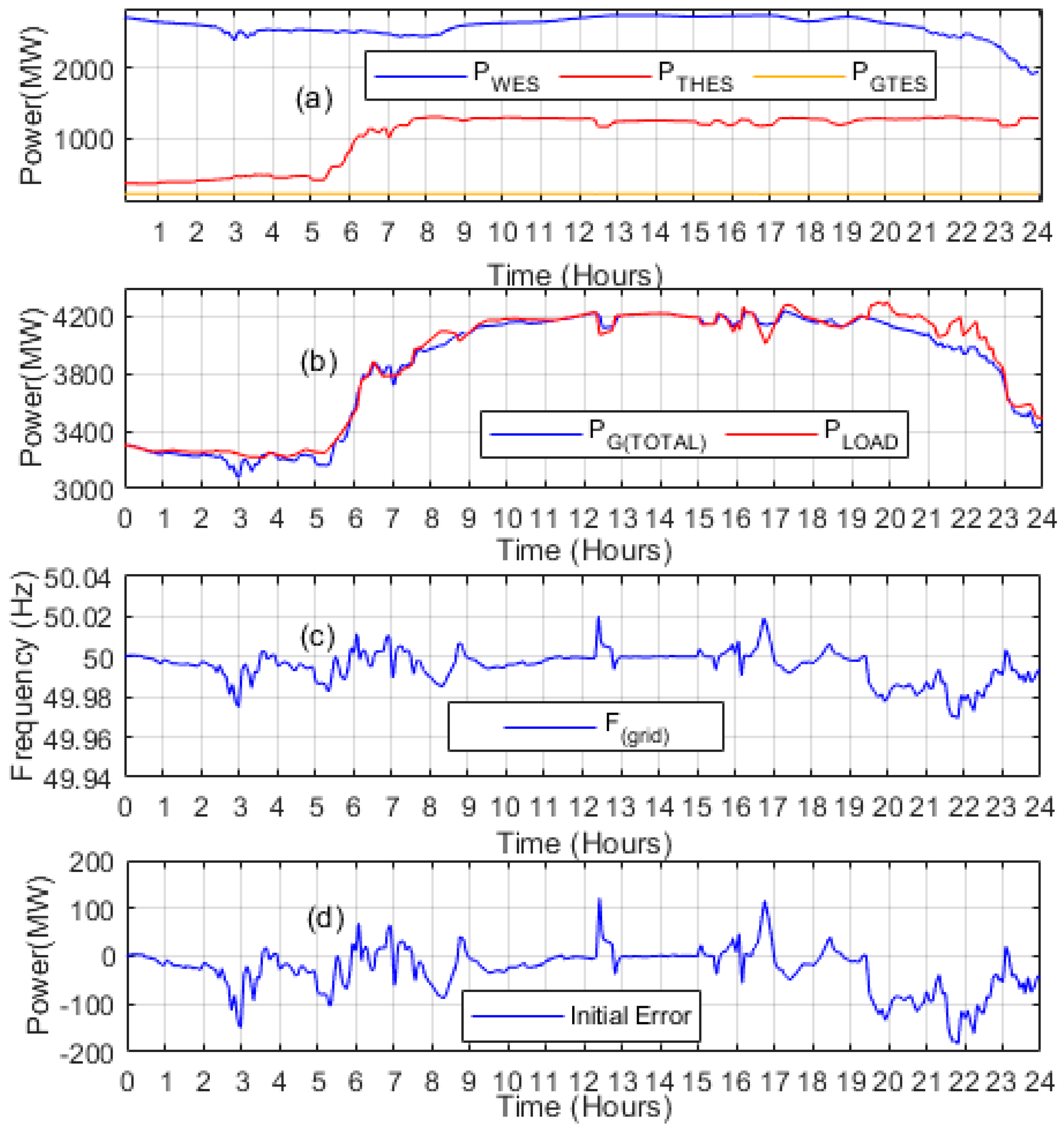
4. Performance Validation

The efficacy of the proposed AGC model was assessed on the established power grid model, comprising TES, GTES, WES, and an EVA model. An external grid with an interval of 16 s and a response rate of 6161 MW/Hz was connected to support the grid. The details regarding the parameters related to the power plant units and the EVA model are listed in Table 1, along with the maximum limits of the secondary operating reserves.
Figure 7a illustrates the actual power generation from various power plant units, comprising TES, GTES, and WES, over 24 h of the Pakistan power system. For data acquisition, a winter day in 2023, was carefully chosen as input data for the TES and WES. However, the GTES power remained constant, maintaining a fixed value throughout the entire period. An essential aspect to consider is that the real inputs of the WES differ from the reference values (forecasted values) initially used to calculate the load-generation balance. Hence, variations between the actual and forecasted values of WES and changing load demands cause a power disparity between power demand and supply, significantly impacting the overall power system performance.
Figure 7b exhibits the disparateness amid the load exigency and cumulative generation from all three sources. The constant alterations in the frequency response of the developed power grid model are clearly illustrated in Figure 7c, revealing the dynamic principle engendered by the oscillating load and generation behaviors. To rectify these power incongruities within the network, this investigation advanced a control strategy for the AGC regulator to optimally use the operating reserves sourced from generating units and EVs. Figure 7d depicts the consequential power asymmetry within the load demand and overall power generation, represented for subsequent comparison. Active power balance management entails multifarious phases. At the outset, disparities in the power grid result in frequency oscillations identified by the governors on individual generating units. Consequently, the governors trigger the utilization of FCRs based on the features of a power plant and the synchronous power of the entire network. These intricate adaptations are crucial for reestablishing balance and stability within the power system. FCRs quickly stabilize the system frequency using governors’ droop characteristics. Secondary reserves fine-tune frequency back to the nominal level. AGC dispatches balancing power to minimize ACE, however, lacks flexibility, increasing costs and risking system security. Hence, a more appropriate approach is required for efficient and secure power system operation.
Implementing an AGC system with a dynamic dispatch approach is crucial. This study proposes a smart power distribution approach for AGC, supporting grid integration with abundant renewable energy resources. The suggested system utilizes EVs and a thermal energy system for power regulation operation in wind energy-based power systems. The AGC system’s dispatch strategy overcomes challenges by integrating EVs. This intelligent power system effectively balances the grid, reducing the need for conventional regulation sources. Hence, it reduces costs and operational stress, while providing an eco-friendly solution, curbing greenhouse effects. The case study demonstrates the efficacy of combining EV storage capacities with TES reserve power for a secondary response, ensuring a stable and responsive power system.

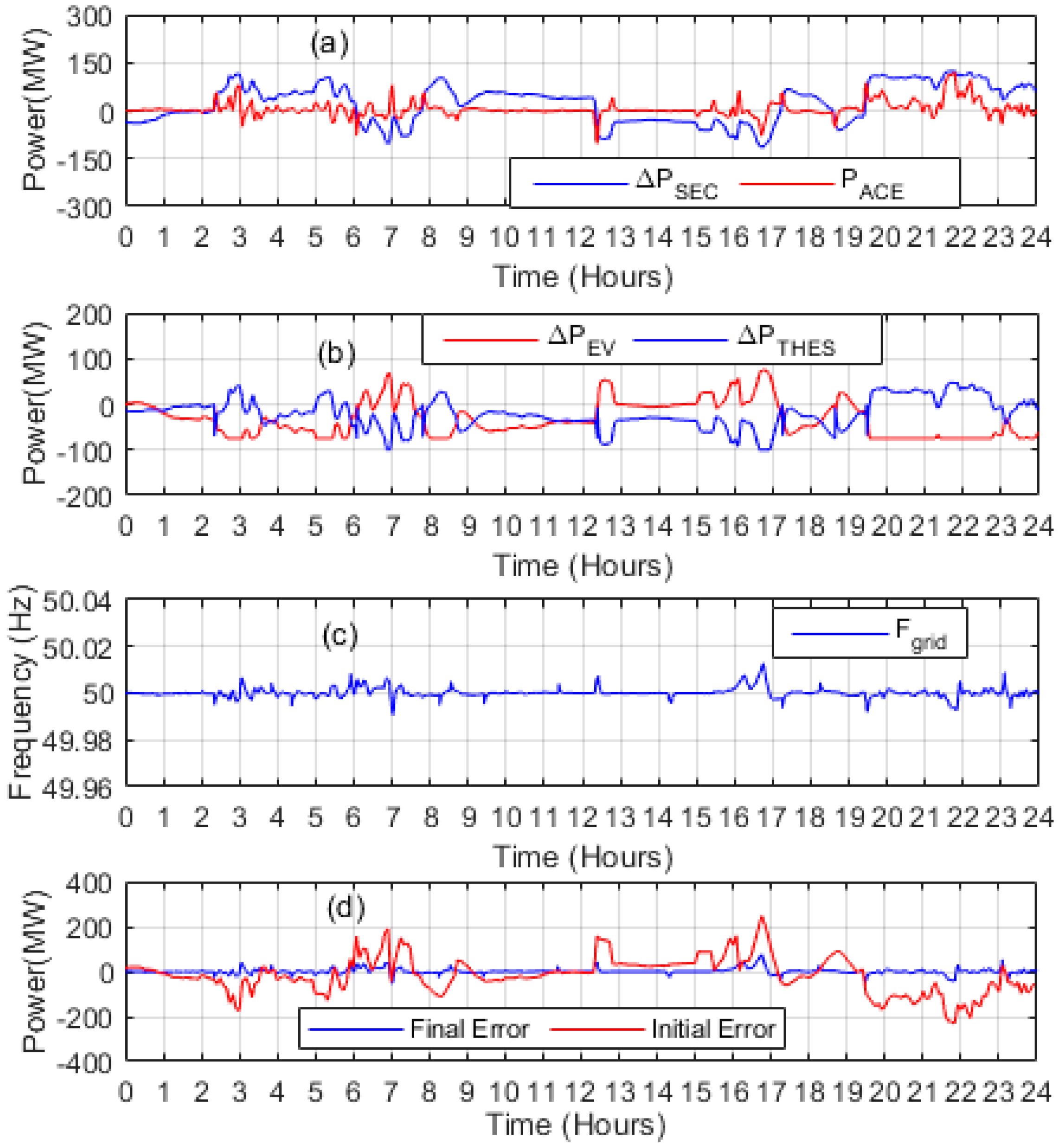
Case Study: Power Balancing through EVA and TES

This case study explores the integration of EVs and TES for power-balancing operations. The study demonstrates how EVs contribute to AGC by providing regulatory power to handle intermittent wind power. The AGC effectively minimizes system frequency deviations by regulating reserves from TES and EVs. The intelligent allocation of operating reserves optimizes power balancing, enhancing overall power system stability and reliability. As shown in Figure 8, the AGC dispatch strategy was developed utilizing EVs’ ability to provide positive and negative regulation strength. The process depicted in Figure 2 systematically determined these capacities. Initial measurements of various parameters led to calculating PRCs and NRCs for each dispatch interval. When PRC P s > 0 , the AGC commanded the EVA to employ all existing reserves before the TES responded. This involved either decreasing the load impact or supplying battery power to the grid. Conversely, during NRC, the battery’s discharge power was increased to counteract the frequency deviation. Integrating EVs facilitated a more advanced and dynamic AGC dispatch, enabling better power balancing control and overall power system efficiency and stability.
The observed occurrence can be recognized as the inferior incremental cost of generating power from EVs. In the NRC, battery power loading is increased solely when the TES hits its lower limit ( P T E S ,   m i n ) , fixed at 20% of its capacity, or when the AGC’s secondary dispatch touches its lower limit ( P T E S ,   m i n ), which equals −100 MW. Figure 7d visually depicts the initial demand and generation imbalance, effectively compensated through the AGC system. The AGC achieves this by dispatching the operating reserves from EVs and the TES. This responsive and dynamic control mechanism efficiently mitigates power imbalances, ensuring grid stability and a dependable power supply.
The cumulative secondary dispatch (Δ P S e c ) from the power sources in the secondary response is visually depicted in Figure 9a, closely tracking the P A C E error. The relatively sluggish response can be ascribed to the inherent delays linked to the AGC system and the power plant units. Figure 9b presents the dispatch (secondary) power producing units ( Δ P E V   a n d   Δ P W P P ). TES responded only after all the reserve power from EVs was utilized during the up-regulation process. This highlights the prioritization of using EV reserves before engaging the TES resources. In scenarios where power generation is exceeded, operating reserves from the TES are rendered before dispatching power from EVs. This approach effectively reduces the incremental cost associated with power generation and enhances overall system efficiency. The strategic deployment of secondary reserves and the coordination between generating units and EVs contribute to successfully managing power imbalances, ensuring optimal grid operation, and minimizing operational costs.
Figure 9c presents the frequency variations observed in the system grid after the AGC’s response. The AGC actions effectively mitigated the frequency deviations, leading to a more stable and controlled power system operation. Figure 9d compares real-time power disparities before and after the AGC response. The AGC intervention significantly reduced power imbalances in generation deficit and generation excess scenarios. This underscores the crucial role of AGC in maintaining grid stability and ensuring that power demand is met efficiently. To measure the EV response, the AGC activated 1.8 GWh of energy from EVs during generation shortages and surpluses. This indicates the substantial contribution of EVs in addressing active power imbalances in a power system characterized by large wind power integration. Without leveraging EVs for power balancing, many conventional power plants would be required to compensate for the imbalances, leading to higher operational costs and reduced sustainability. Thus, integrating EVs into the AGC process is a valuable solution for power system operators, providing dynamic and cost-effective reserve resources to enhance grid reliability and accommodate the intermittent nature of renewable energy sources.
Additionally, the study conducted a quantitative analysis to enhance the understanding, and compare the outcomes, of the AGC control system with the initial system error. This involved calculating the area under the positive and negative curves depicted in Figure 9d; the results have been presented in Table 2. These findings demonstrated a significant reduction in power error due to integrating large-scale wind energy systems into the network.

5. Conclusions and Future Directions

This research conducted an extensive analysis of providing active power support to power systems heavily reliant on wind integration, utilizing the capacities of EVs in conjunction with TES. Wind-based power systems inherently possess an intermittent character, leading to forecasting errors that cause power imbalances between demand and generation. Additional operating reserves of traditional power plants often seek to meet the increased reserve requirements. However, such an approach is economically impractical and burdensome to the environment. Hence, in the current study, a real-time dynamic dispatch strategy was formulated for the AGC system to utilize EV capabilities in secondary power dispatch processes. A case study was conducted, integrating EVs into the proposed AGC system alongside the TES to offer regulation services. The performance analysis demonstrates that the integration of EVs with TES can substantially alleviate real-time power imbalances stemming from extensive wind power integration, elevating system operational security and reliability. Further, the quantitative comparison conducted in this study highlights the significant cost savings achieved through the reduced reliance on conventional power plants, underscoring the valuable role of EVs in the power system. Hence, this research provides valuable insights for power system operators to strategically leverage EVs as a dynamic and cost-effective solution to address power imbalances and improve power systems’ overall sustainability and efficiency.
The study lays a strong foundation for future extensions, particularly in an artificial intelligence (AI)-based AGC system. The power system’s operational parameters can be accurately forecasted using AI techniques like machine learning and predictive analytics. Moreover, while the current control system was tailored for a power system with substantial inertia, it holds promise for application in future micro-grid scenarios where system inertia is minimal due to the massive integration of renewable energy sources. This adaptability highlights the versatility of the suggested control system, making it well-suited for diverse power system configurations and ensuring its relevance in the face of evolving energy landscapes. Additionally, integrating building loads, particularly those utilized for heating or cooling purposes, represents a crucial avenue for future exploration. By incorporating building loads alongside EVs in the proposed control strategies, the potential for harnessing energy from diverse sources becomes more comprehensive. This integration could lead to a scenario where the reserve capacity obtained from traditional generation sources is fully replaced, resulting in a more sustainable and eco-friendly power system.

Author Contributions

Conceptualization, Z.U., K.U., C.D.-L., G.G. and A.B.; Methodology, Z.U., K.U. and C.D.-L.; Software, Z.U., K.U. and A.B.; Validation, Z.U., K.U. and G.G.; Formal analysis, C.D.-L. and G.G.; Investigation, Z.U., K.U. and A.B.; Resources, C.D.-L. and G.G.; Data curation, K.U. and A.B.; Writing—original draft, Z.U., K.U., A.B. and C.D.-L.; Writing—review & editing, K.U., C.D.-L., G.G. and A.B.; Visualization, K.U., C.D.-L. and A.B.; Supervision, G.G.; Project administration, C.D.-L. and G.G. All authors have read and agreed to the published version of the manuscript.

Funding

This research received no external funding.

Data Availability Statement

This study did not report any data.

Conflicts of Interest

The authors declare no conflict of interest.

Abbreviations

AcronymDefinition
BESsBattery Energy Storage System
PAUp-regulation area
CESsCapacitive Energy Storage System
CEVEnvironmental Burning Capacity
CFMBaseload function
CIGREInternational Council on Large Electric Systems
CSEVSequential Environmental burner capacity
CVGVVariable inlet guide vane position compressor capacity
FCRFrequency Containment Reserve
FRRFrequency Regulation Reserves
GTDBGas turbine dynamics block
GTESGas Turbine Energy System
NRCNegative regulation capacity
NADown-regulation area
PDBPower distribution block
PLBPower limitation block
PJMRegional Transmission Company
RPSReference Power Signal
SEVSequential environmental combustion
SMASmart Management Approach
STCSteam Temperature Control
SEVSequential environmental combustion
TSOTransmission system operator
TESThermal Energy System

References

  1. Lee, T.-Y. Optimal Spinning Reserve for a Wind-Thermal Power System Using EIPSO. IEEE Trans. Power Syst. 2007, 22, 1612–1621. [Google Scholar] [CrossRef]
  2. Nassar, I.A.; Abdella, M.M. Impact of replacing thermal power plants by renewable energy on the power system. Therm. Sci. Eng. Prog. 2018, 5, 506–515. [Google Scholar] [CrossRef]
  3. Albadi, M.; El-Saadany, E. Comparative study on impacts of wind profiles on thermal units scheduling costs. IET Renew. Power Gener. 2011, 5, 26–35. [Google Scholar] [CrossRef]
  4. Hashmi, M.H.; Ullah, Z.; Asghar, R.; Shaker, B.; Tariq, M.; Saleem, H. An Overview of the current challenges and Issues in Smart Grid Technologies. In Proceedings of the 2023 International Conference on Emerging Power Technologies (ICEPT), Topi, Pakistan, 6–7 May 2023; pp. 1–6. [Google Scholar] [CrossRef]
  5. Hussain, S.; Lai, C.; Eicker, U. Flexibility: Literature review on concepts, modeling, and provision method in smart grid. Sustain. Energy Grids Netw. 2023, 35, 101113. [Google Scholar] [CrossRef]
  6. Asghar, R.; Fulginei, F.R.; Wadood, H.; Saeed, S. A Review of Load Frequency Control Schemes Deployed for Wind-Integrated Power Systems. Sustainability 2023, 15, 8380. [Google Scholar] [CrossRef]
  7. Ullah, K.; Ullah, Z.; Aslam, S.; Salam, M.S.; Salahuddin, M.A.; Umer, M.F.; Humayon, M.; Shaheer, H. Wind Farms and Flexible Loads Contribution in Automatic Generation Control: An Extensive Review and Simulation. Energies 2023, 16, 5498. [Google Scholar] [CrossRef]
  8. Asghar, R.; Ullah, Z.; Azeem, B.; Aslam, S.; Hashmi, M.H.; Rasool, E.; Shaker, B.; Anwar, M.J.; Mustafa, K. Wind Energy Potential in Pakistan: A Feasibility Study in Sindh Province. Energies 2022, 15, 8333. [Google Scholar] [CrossRef]
  9. Guille, C.; Gross, G. A conceptual framework for the vehicle-to-grid (V2G) implementation. Energy Policy 2009, 37, 4379–4390. [Google Scholar] [CrossRef]
  10. Khooban, M.-H. Secondary Load Frequency Control of Time-Delay Stand-Alone Microgrids With Electric Vehicles. IEEE Trans. Ind. Electron. 2017, 65, 7416–7422. [Google Scholar] [CrossRef]
  11. Li, Z.; Su, S.; Jin, X.; Chen, H.; Li, Y.; Zhang, R. A hierarchical scheduling method of active distribution network considering flexible loads in office buildings. Int. J. Electr. Power Energy Syst. 2021, 131, 106768. [Google Scholar] [CrossRef]
  12. Mignoni, N.; Scarabaggio, P.; Carli, R.; Dotoli, M. Control frameworks for transactive energy storage services in energy communities. Control Eng. Pract. 2023, 130, 105364. [Google Scholar] [CrossRef]
  13. Venkatesan, K.; Govindarajan, U. Optimal power flow control of hybrid renewable energy system with energy storage: A WOANN strategy. J. Renew. Sustain. Energy 2019, 11, 015501. [Google Scholar] [CrossRef]
  14. Hernández, J.; Sanchez-Sutil, F.; Vidal, P.; Rus-Casas, C. Primary frequency control and dynamic grid support for vehicle-to-grid in transmission systems. Int. J. Electr. Power Energy Syst. 2018, 100, 152–166. [Google Scholar] [CrossRef]
  15. Falahati, S.; Taher, S.A.; Shahidehpour, M. A new smart charging method for EVs for frequency control of smart grid. Int. J. Electr. Power Energy Syst. 2016, 83, 458–469. [Google Scholar] [CrossRef]
  16. Giordano, F.; Arrigo, F.; Diaz-Londono, C.; Spertino, F.; Ruiz, F. Forecast-Based V2G Aggregation Model for Day-Ahead and Real-Time Operations. In Proceedings of the 2020 IEEE Power & Energy Society Innovative Smart Grid Technologies Conference (ISGT), Washington, DC, USA, 17–20 February 2020; pp. 1–5. [Google Scholar] [CrossRef]
  17. Diaz-Londono, C.; Gruosso, G.; Maffezzoni, P.; Daniel, L. Coordination Strategies for Electric Vehicle Chargers Integration in Electrical Grids. In Proceedings of the 2022 IEEE Vehicle Power and Propulsion Conference (VPPC), Merced, CA, USA, 1–4 November 2022; IEEE: Piscataway, NJ, USA; pp. 1–6. [Google Scholar]
  18. Diaz-Londono, C.; Vuelvas, J.; Gruosso, G.; Correa-Florez, C.A. Remuneration Sensitivity Analysis in Prosumer and Aggregator Strategies by Controlling Electric Vehicle Chargers. Energies 2022, 15, 6913. [Google Scholar] [CrossRef]
  19. Mignoni, N.; Carli, R.; Dotoli, M. Distributed Noncooperative MPC for Energy Scheduling of Charging and Trading Electric Vehicles in Energy Communities. IEEE Trans. Control Syst. Technol. 2023, 31, 2159–2172. [Google Scholar] [CrossRef]
  20. Hosseini, S.M.; Carli, R.; Parisio, A.; Dotoli, M. Robust Decentralized Charge Control of Electric Vehicles under Uncertainty on Inelastic Demand and Energy Pricing. In Proceedings of the 2020 IEEE International Conference on Systems, Man, and Cybernetics (SMC), Toronto, ON, Canada, 11–14 October 2020; pp. 1834–1839. [Google Scholar] [CrossRef]
  21. Knezovic, K.; Martinenas, S.; Andersen, P.B.; Zecchino, A.; Marinelli, M. Enhancing the Role of Electric Vehicles in the Power Grid: Field Validation of Multiple Ancillary Services. IEEE Trans. Transp. Electrif. 2016, 3, 201–209. [Google Scholar] [CrossRef]
  22. Falvo, M.C.; Sbordone, D.; Bayram, I.S.; Devetsikiotis, M. EV charging stations and modes: International standards. In Proceedings of the IEEE International Symposium on Power Electronics, Electrical Drives, Automation and Motion, Ischia, Italy, 18–20 June 2014; pp. 1134–1139. [Google Scholar]
  23. Cui, Y.; Hu, Z.; Luo, H. Optimal Day-Ahead Charging and Frequency Reserve Scheduling of Electric Vehicles Considering the Regulation Signal Uncertainty. IEEE Trans. Ind. Appl. 2020, 56, 5824–5835. [Google Scholar] [CrossRef]
  24. Tushar, M.H.K.; Zeineddine, A.W.; Assi, C.M. Demand-Side Management by Regulating Charging and Discharging of the EV, ESS, and Utilizing Renewable Energy. IEEE Trans. Ind. Inform. 2018, 14, 117–126. [Google Scholar] [CrossRef]
  25. Liu, H.; Qi, J.; Wang, J.; Li, P.; Li, C.; Wei, H. EV Dispatch Control for Supplementary Frequency Regulation Considering the Expectation of EV Owners. IEEE Trans. Smart Grid 2016, 9, 3763–3772. [Google Scholar] [CrossRef]
  26. Pham, T.N.; Trinh, H.; Van Hien, L. Load Frequency Control of Power Systems With Electric Vehicles and Diverse Transmission Links Using Distributed Functional Observers. IEEE Trans. Smart Grid 2015, 7, 238–252. [Google Scholar] [CrossRef]
  27. Sanki, P.; Basu, M.; Pal, P.S.; Das, D. Application of a novel PIPDF controller in an improved plug-in electric vehicle integrated power system for AGC operation. Int. J. Ambient. Energy 2021, 43, 4767–4781. [Google Scholar] [CrossRef]
  28. Khezri, R.; Oshnoei, A.; Hagh, M.T.; Muyeen, S. Coordination of Heat Pumps, Electric Vehicles and AGC for Efficient LFC in a Smart Hybrid Power System via SCA-Based Optimized FOPID Controllers. Energies 2018, 11, 420. [Google Scholar] [CrossRef]
  29. Gruoup, I.W. Dynamic Models For Fossil FUELED Steam Units In Power System Studies. IEEE Trans. Power Syst. 1991, 6, 753–761. [Google Scholar]
  30. Suwannarat, A. Integration and Control of Wind Farms in the Danish Electricity System; Institut for Energiteknik, Aalborg Universitet: Aalborg East, Denmark, 2008; Available online: https://vbn.aau.dk/ws/portalfiles/portal/7254073/Suwannarat.pdf (accessed on 13 September 2023).
Figure 1. Flow chart for calculation of PRC and NRC.
Energies 16 07118 g001
Figure 2. Calculation of PRC and NRC of EVs.
Energies 16 07118 g002
Figure 3. Thermal energy system model.
Energies 16 07118 g003
Figure 4. Gas turbine energy system model (GTES).
Energies 16 07118 g004
Figure 5. Wind energy system model.
Energies 16 07118 g005
Figure 6. Optimized power system AGC network.
Energies 16 07118 g006
Figure 7. (a) Power generation, (b) net load and power demand, (c) frequency, (d) power demand error.
Energies 16 07118 g007
Figure 8. EVs and TES integration process.
Energies 16 07118 g008
Figure 9. (a) ACE and power dispatch, (b) TES and EVs individual dispatch, (c) resulted system frequency, (d) power imbalances comparison.
Energies 16 07118 g009
Table 1. Parameter data for power plant units and the EVA system.
Generating Units (MW)TES GTESWES EVA
Maximum Power (MW)17552222820 127.5
Operating Reserves (MW) ± 100 0−500 ± 75
Table 2. Quantitative comparative analysis.
Case StudiesUp-Regulation Area
( 10 6 )
Down-Regulation Area
( 10 6 )
% Reduction
in Positive
Regulation Error
% Reduction
in Negative
Regulation Error
Initial Error3.1374.1350.00%0.00%
Case Study0.34710.214590.0%93.25%
Disclaimer/Publisher’s Note: The statements, opinions and data contained in all publications are solely those of the individual author(s) and contributor(s) and not of MDPI and/or the editor(s). MDPI and/or the editor(s) disclaim responsibility for any injury to people or property resulting from any ideas, methods, instructions or products referred to in the content.

