Article

Failure Mechanism of Integrity of Cement Sheath under the Coupling Effect of Formation Creep and Temperature during the Operation of Salt Rock Gas Storage

1
Key Laboratory of Unconventional Oil & Gas Development, China University of Petroleum (East China), Qingdao 266580, China
2
School of Petroleum Engineering, China University of Petroleum (East China), Qingdao 266580, China
*
Author to whom correspondence should be addressed.
Energies 2023, 16(20), 7089; https://doi.org/10.3390/en16207089
Submission received: 11 August 2023 / Revised: 11 September 2023 / Accepted: 13 October 2023 / Published: 13 October 2023
(This article belongs to the Special Issue Advances in Reservoir Simulation)

Abstract

:
Maintaining the integrity of the cement sheath is essential for the sealing of underground gas storage. The formation creep, temperature changes, and operating pressure changes during the operation of underground gas storage can cause changes in the stress of the cement sheath, which probably induces the failure of the cement sheath’s integrity. A creep model taking the effects of stress and temperature into account is developed to study the cement sheath’s integrity in creep formation, and the feasibility of creep simulation via finite element method is verified. The finite element method is used to analyze the effects of formation creep, temperature, operating pressure, and the cement sheath’s elastic modulus on the cement sheath’s integrity. The result shows that the coupling effect of formation creep and temperature increases the cement sheath’s failure risk; both the formation creep and the decrease in cement sheath temperature increase the Von Mises stress on the cement sheath, increasing the risk of the cement sheath’s shear failure. The decrease in cement sheath temperature decreases the circumferential compressive stress on the cement sheath and raises the risk of the cement sheath’s tensile failure. Shear failure of the cement sheath occurs at high operating pressure upper limits. The operating pressure is less than 70 MPa, or the cement sheath’s elastic modulus is less than 3 GPa, which can prevent the failure of the cement sheath’s integrity during the operation of underground gas storage.

1. Introduction

Salt rock exhibits extremely low permeability and porosity [1], making it a commonly employed choice as a sealing caprock for depleted oil and gas reservoirs [2]. Under deviatoric stress, the salt rock formation will creep and compress the cement sheath, potentially resulting in the failure of the cement sheath’s integrity (CSI). The operation of underground gas storage (UGS) includes gas injection and gas production phases. The gas injected into the wellbore undergoes heat exchange with the assembly comprising the downhole casing, cement sheath, and formation. Alterations in the assembly’s temperature can subsequently impact the stress state of the cement sheath [3], potentially leading to compromised CSI. Variations in the operating pressure of UGS can also cause changes in the stress state of the cement sheath, potentially leading to compromised integrity. Weakening of the CSI will diminish its capacity to seal effectively. This could potentially result in the escape of gas from the UGS, carrying negative consequences for safety, the environment, and the economy [4]. The failure types of CSI include shear failure (i.e., compressive failure), debonding failure, and tensile failure (i.e., radial crack) [5,6,7]. The Von Mises criterion [8,9,10,11,12,13], Tresca criterion [14,15], Mohr–Coulomb criterion [5,16,17], and Drucker–Prager criterion [18,19] are often used to judge the cement sheath’s shear failure. The cement sheath’s shear failure can produce plastic strain. The cement sheath’s tensile failure is evaluated by the maximum tensile stress criterion [20,21,22]. When the cement sheath’s circumferential stress surpasses its ability to withstand tension, tensile failure occurs. The cement sheath’s debonding failure is evaluated by the interfacial radial stress. When the interfacial radial tensile stress surpasses its bonding strength, debonding failure occurs [23,24].
Liu [25] and Orlic [26,27] studied the impact of formation creep on the closure of the wellbore. Their research results indicated that wellbore closure can be triggered by salt formation creep, and the greater the wellbore’s Von Mises stress, the faster the wellbore closure rate. Melo [28], Yu [29], and Velilla [30] have investigated the effect of salt formation’s creep on casing. The result indicated that salt rock creep can cause increased casing stress and may cause casing yield failure. Jandhyala [9] investigated the effect of formation creep on the cement sheath. The result indicated that the cement with a higher elasticity has a stronger bearing capacity. Jesus [5], Raoof [31], and Yin [3] investigated the effect of downhole temperature changes on CSI. The finding showed that the decrease in temperature may cause the debonding failure. Zhang [16] analyzed the CSI during the operation of UGS using elastoplastic theory. The findings indicated that shear failure may occur when the casing is pressurized; during casing pressure relief, debonding failure may occur. Yang [2] used the finite element method (FEM) to investigate the effect of the creep of salt formation on CSI within UGS, considering non-uniform in situ stress conditions. The finding showed that salt rock creep under non-uniform in situ stress can cause the cement sheath’s shear failure. The greater the non-uniform in situ stress, the earlier the shear failure occurs. In summary, scholars’ research mainly focuses on the influences of the salt formation’s creep on wellbore closure and casing failure. However, few studies have investigated the failure of CSI in the salt formation of UGS. In investigations concerning the influence of salt formation creep on CSI, the influence of downhole temperature fluctuations on both formation creep and CSI has been overlooked. In investigations concerning the failure of CSI during the operation of UGS, the impact of downhole temperature fluctuations on the cement sheath’s integrity has been overlooked. Therefore, studying the effects of formation creep, downhole temperature changes, and the operating pressure on CSI throughout UGS operations holds immense importance in ensuring UGS safety.
In this study, a creep model for salt rock was developed by conducting creep experiments that involved subjecting the salt rock to varying temperature and pressure loads. The feasibility of simulating salt rock creep using the FEM is verified by comparing the FEM-simulated steady-state creep rate of salt rock with the steady-state creep rate obtained in actual salt rock creep experiments. By establishing an FEM model of casing–cement sheath–creep formation assembly, the effects of salt rock formation creep, temperature changes, and the upper limit of operating pressure on the CSI throughout the operation of UGS were studied. The influences of these factors on the CSI were determined. By examining how variations in the cement sheath’s elastic modulus impact its integrity, measures to avert the failure of the CSI during the operation of UGS were obtained. The findings from this study offer valuable insights into the potential integrity issues concerning cement sheaths in UGS wells. These results hold significant importance in terms of averting cement sheath integrity failures and ensuring the secure and effective functioning of the operation of UGS.

2. Establishment of FEM Model for Casing–Cement Sheath–Creep Formation Combination

In this section, a salt rock creep model is obtained from the salt rock creep experiments at firs; then, the feasibility of salt rock creep simulations in FEM is verified by comparing the steady-state creep rates between FEM simulations and salt rock creep experiments. Finally, an FEM model of the combined casing–cement sheath–creep formation is developed based on the salt rock creep model obtained from experiments.

2.1. Salt Rock Creep Model

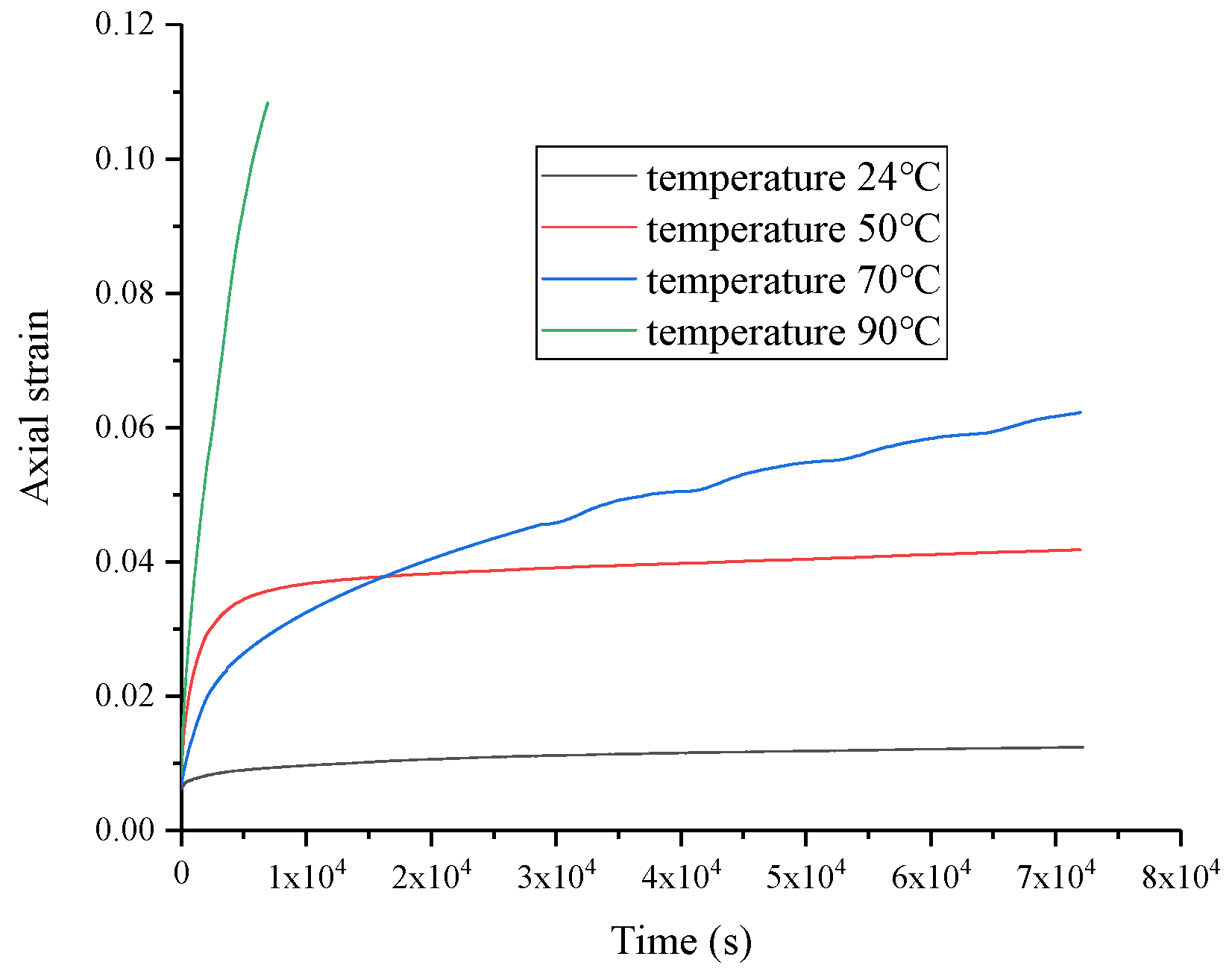
In order to develop the FEM model for the casing–cement sheath–creep formation assembly, it is necessary to acquire the creep model of the creep formation. Consequently, we conducted creep experiments on salt rock under various temperatures and pressures. The salt rock creep model can be derived by fitting the results of salt rock creep experiments. The experimental equipment used in the salt rock creep experiment is GCTS RTR-2000. The length-to-diameter ratio for the experimental salt rock creep samples is 2:1, which is consistent with the experimental criteria of rock mechanics. The temperature and pressure loads applied to the samples are shown in Table 1. The deviator stress is determined as the disparity between the axial pressure and the confining pressure. Sample numbers 1–5 refer to creep experiments conducted on salt rock under various deviatoric stress conditions, and sample numbers 3, 6, 7, and 8 refer to creep experiments conducted on salt rock under various temperatures. The figures illustrate the creep behavior of salt rock at varying deviatoric stresses (Figure 1) and varying temperatures (Figure 2). As depicted in Figure 1, higher deviator stress corresponds to increased axial strain. Moreover, elevated deviator stress leads to a more rapid increase in axial strain. As depicted in Figure 2, higher temperature corresponds to increased axial strain. Furthermore, elevated temperature leads to a more rapid increase in axial strain. Table 2 displays the steady-state creep rates for diverse samples. Higher deviator stress corresponds to an increased steady-state creep rate, indicating that the deviator stress promotes creep. Higher temperature corresponds to an increased steady-state creep rate, indicating that temperature promotes creep.
During the long-term creep process, compared to transition and accelerated creep stages, the duration of steady-state creep is the longest, and the creep strain of long-term creep is mainly contributed by steady-state creep. Therefore, the salt rock creep model mainly focuses on steady-state creep. Currently, the commonly used creep model that represents the influences of temperature and stress on the steady-state creep rate is the hyperbolic sine law model [30,32,33,34,35,36,37,38], as shown in Equation (1):
ε c r = A ( sinhB q ) n exp ( Δ H R ( θ θ Z ) ) ,
where ε c r represents the steady-state creep rate (−1); q represents the Von Mises stress (MPa); θ represents the temperature (°C); θ Z represents the absolute zero in temperature (−273.15 °C); R represents the universal gas constant (8314.3 mJ/(mol·°C)); Δ H represents the activation energy (mJ/mol); and A, B, and n are material parameters.
The Von Mises stress in Equation (1) equals to the deviator stress in the salt rock creep experiment. We use MATLAB curve fitting tool to fit the data in Table 2, and the fitting result is shown in Equation (2), where R2 = 0.9442 indicates that the goodness of fit is close to 1, showing a favorable fitting outcome. Equation (2) effectively portrays the interplay between temperature, stress, and the steady-state creep rate:
ε c r = 32.31 ( sinh 0.2186 q ) 1.197 exp ( 6.097 × 10 7 8314.3 ( θ + 273.15 ) ) , R 2 = 0.9442

2.2. Feasibility Verification of Salt Rock Creep Simulation in FEM

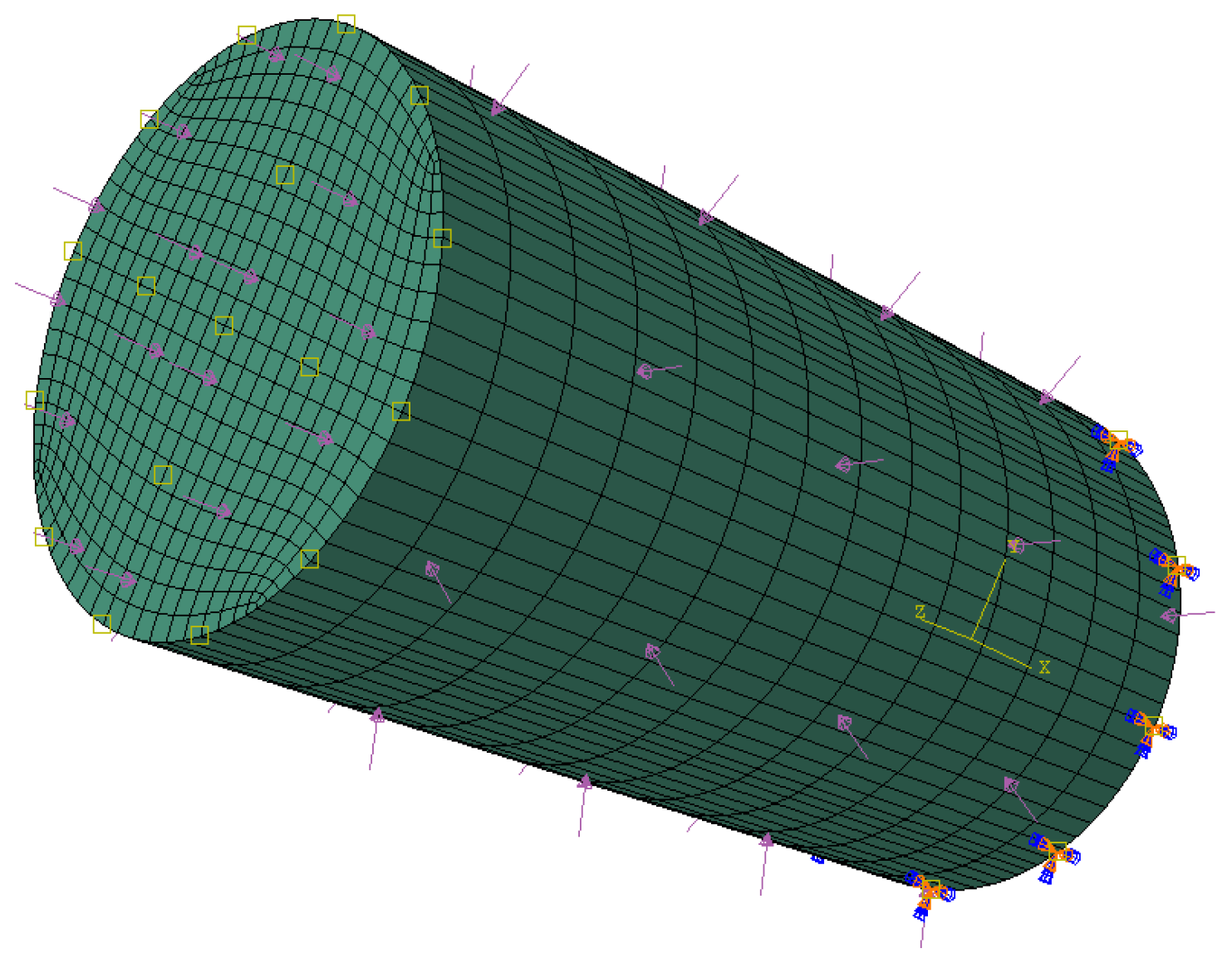
Using Equation (2), we establish an FEM model in ABAQUS that replicates the dimensions of the salt rock creep experimental specimen, as depicted in Figure 3. The entire model is loaded with temperature load, the top surface is loaded with axial pressure, the side surface is loaded with confining pressure, and the bottom of the model is immovable. The steady-state creep rates of salt rock creep experiments and finite element simulations under different temperature and pressure loads are illustrated in Figure 4. The steady-state creep rates of salt rock creep experiments and the steady-state creep rates of finite element simulation have a good consistency, indicating that finite element simulation can well reflect the steady-state creep rate of salt rock at varying temperatures and pressure loads, verifying the feasibility of salt rock creep simulation in FEM.

2.3. FEM Model of Casing–Cement Sheath–Creep Formation Combination

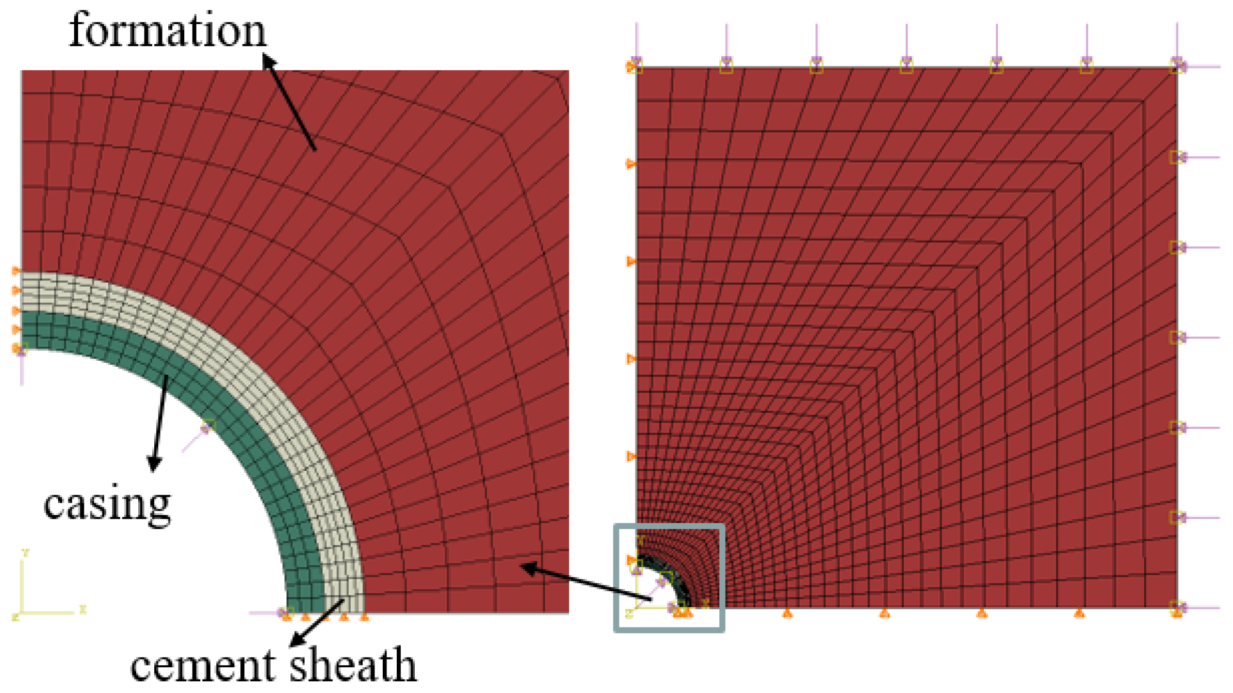
The FEM model of the casing–cement sheath–formation combination in a salt rock formation at a well depth of 2500 m in an UGS is established. The axial strain of the casing–cement sheath–formation combination is very small and can be ignored. According to the theory of elasticity, the casing–cement sheath–formation combination can be simplified as a plane strain model [2], as illustrated in Figure 5. The model’s geometric parameters are detailed in Table 3, and the model’s physical attributes are detailed in Table 4. The mesh type is CPE4T. The contact methodology adopted for interactions between the casing and cement sheath, as well as for those between the cement sheath and the formation, are as follows: normal behavior is hard contact; tangential behavior is frictionless. The casing’s yield strength is 758 MPa. The cement sheath’s compressive strength is 42.13 MPa, along with a tensile strength of 3.99 MPa. The bonding strength between cement sheath and casing is 1.23 MPa. The formation creep model is shown in Equation (2). The formation temperature and uniform in situ stress are exerted onto the upper and right boundaries of the model. The casing internal pressure (i.e., operating pressure) and gas injection temperature are exerted onto the casing’s inner wall. Symmetric constraints are exerted onto the model’s lower and left boundaries. The uniform in situ stress and temperature of the model come from a real case. The uniform in situ stress is 50 MPa. The formation temperature is 90 °C. The gas injection temperature is 20 °C. The model’s initial temperature is 90 °C.
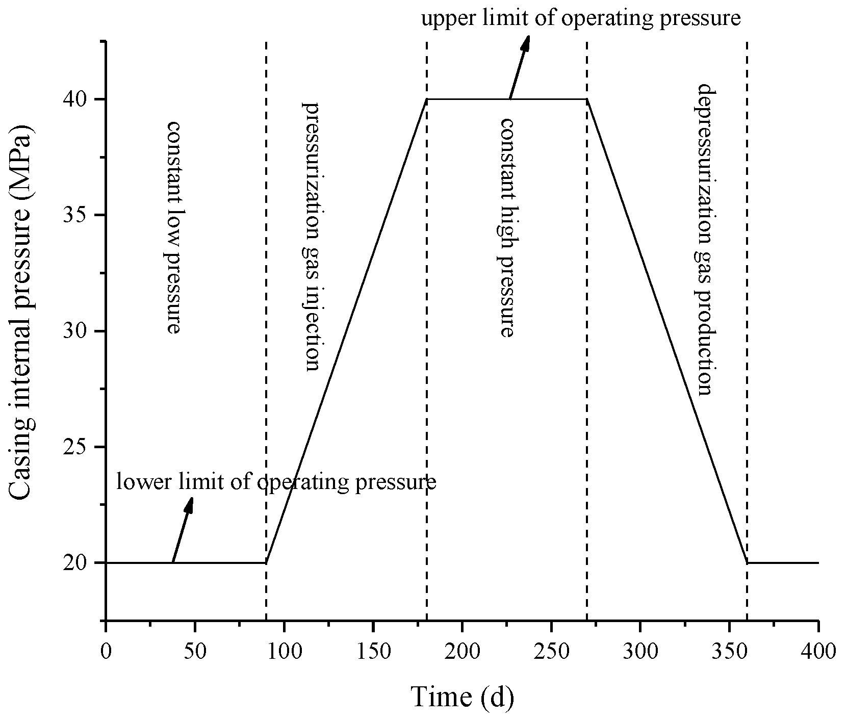
The operating pressure of UGS for one cycle is shown in Figure 6. The operating cycle of UGS includes four stages: constant low pressure, pressurization gas injection, constant high pressure, and depressurization gas production. The upper and lower limit operating pressure are crucial parameters. The duration of one cycle of UGS operation is one year, and the duration of each operation phase is three months.

3. Results and Discussion

3.1. Variation of Formation Temperature and Stress during Operation of UGS

Creep refers to the increase in the strain of an object over time under a fixed load. The formation in the combination model in this paper is a salt rock formation with creep characteristics. When subjected to a constant load, the salt rock formation will undergo creep, exerting pressure on the cement sheath. This continuous pressure escalation on the cement sheath could potentially result in an eventual integrity failure. Therefore, it is imperative to investigate the variation of temperature and stress over time in the formation near the borehole during the operation of UGS to determine when the salt rock formation will creep during the UGS’s operation.
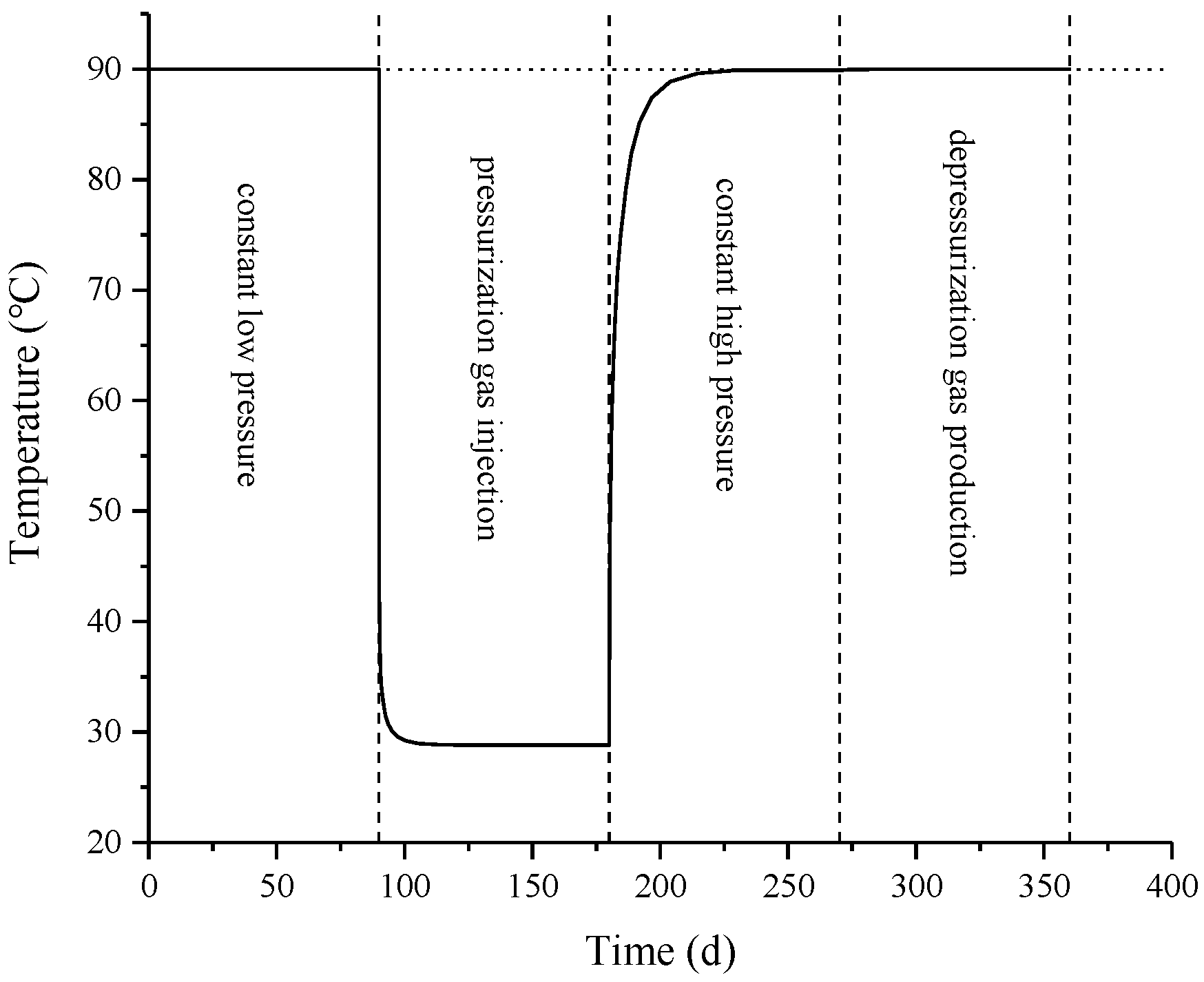
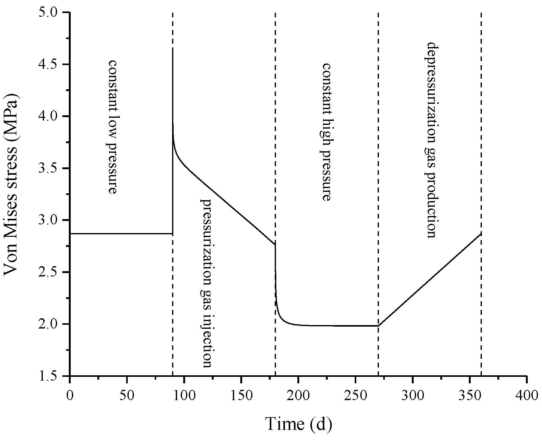
The remaining parameters remain unchanged, regardless of formation creep. The UGS has an upper operating pressure limit of 40 MPa and a lower operating pressure limit of 20 MPa. To simulate a full UGS operation cycle, we study the temperature and stress changes in the formation near the borehole and determine when the salt rock formation will occur creep. Figure 7 illustrates the alteration in temperature within the inner wall of the formation over a duration of UGS operation, while Figure 8 presents the corresponding changes in Von Mises stress. The observations from Figure 7 and Figure 8 reveal that during the constant low pressure stage, the temperature and Von Mises stress acting on the formation’s inner wall always remain unchanged. During the pressurized gas injection stage, the temperature of the formation’s inner wall rapidly decreases, resulting in a large thermal stress and leading to a rapid escalation of Von Mises stress on the formation’s inner wall. Subsequently, with gradual stabilization of the formation temperature and a concurrent increase in casing internal pressure, the Von Mises stress on the formation’s inner wall gradually decreases. During the constant high pressure stage, the temperature of the formation’s inner wall gradually recovers and eventually reaches a stable state, leading to a gradual decline and subsequent stabilization of the Von Mises stress of the formation’s inner wall. During the depressurization gas production stage, the temperature of the formation’s inner wall remains unchanged, while the casing internal pressure gradually decreases, resulting in a gradual increase in Von Mises stress on the formation’s inner wall. Based on the preceding analysis, it is evident that during the constant low pressure stage, the Von Mises stress of the formation always remain unchanged, so the formation will occur creep at this stage. During the pressurized gas injection stage, the formation’s Von Mises stress is not constant, so the formation will not occur creep at this stage. During the later period of the constant high pressure stage, the formation’s Von Mises stress remains unchanged, and the formation will occur creep during this time period. During the depressurization gas production stage, the formation’s Von Mises stress is not constant, so the formation will not occur creep at this stage.
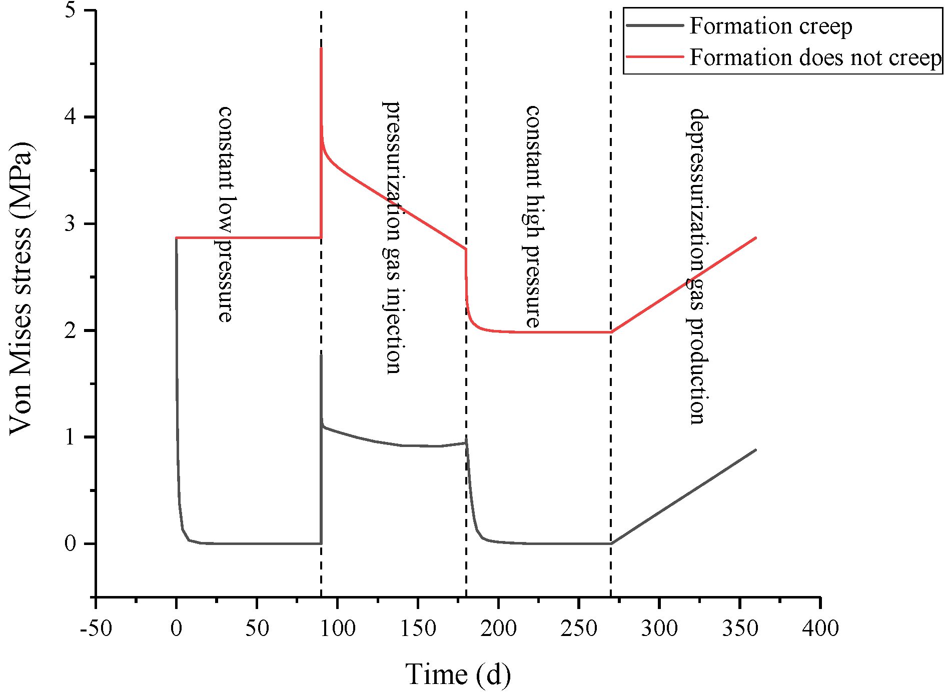
The other parameters of the model remain constant, taking into account the formation creep that occurs during the stages of constant low pressure and constant high pressure. The UGS is operated for one cycle; the comparison of the Von Mises stress of the formation’s inner wall with and without formation creep is illustrated in Figure 9. As depicted in Figure 9, in the case of formation creep, the formation’s Von Mises stress experiences a decline during both the constant low-pressure and constant high-pressure stages, gradually converging toward zero. The formation creep compresses the cement sheath, which plays a resistance role to the formation creep, causing the radial stress of the formation’s inner wall to increase, the Von Mises stress of the formation’s inner wall to decrease, and the ability of formation creep to decrease.

3.2. Effects of Downhole Temperature Changes and Formation Creep on Integrity Failure of Cement Sheath

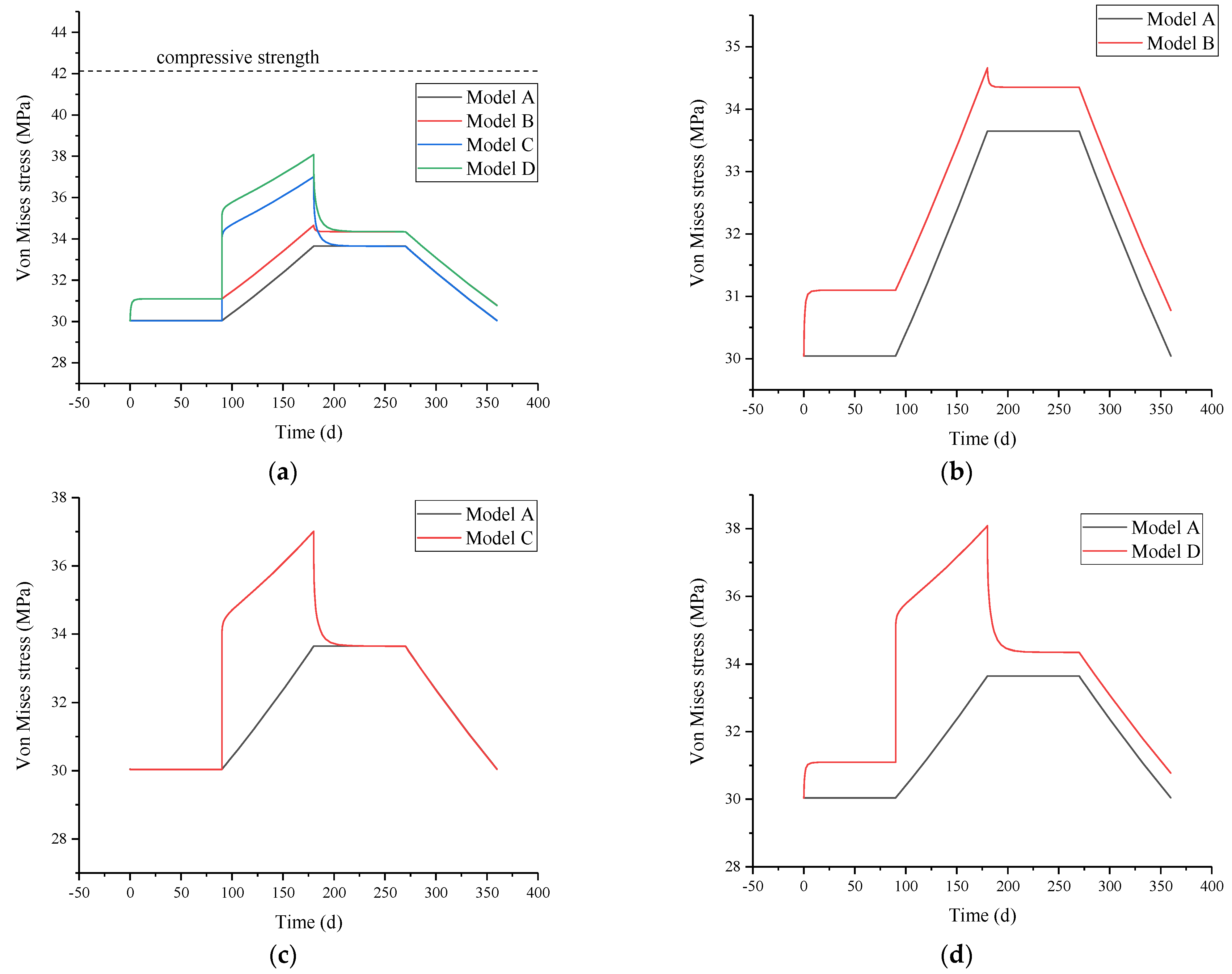
To investigate the effect of downhole temperature fluctuations, formation creep, and the combined influence of these two factors on the CSI during the operation of UGS, four different combination models were established, as shown in Table 5. Model A: the impact of downhole temperature changes and formation creep is not considered; Model B: not considering downhole temperature changes but considering the impact of formation creep; Model C: not considering formation creep but considering the influence of downhole temperature changes; Model D: considering the influence of downhole temperature changes and formation creep. The comparison between Model A and Model B can determine the impact of formation creep on the CSI. The comparison between Model A and Model C can determine the influence of downhole temperature changes on the CSI. The comparison between Model A and Model D can determine the impact of the combined effects of downhole temperature changes and formation creep on the CSI. In this study, the cement sheath’s shear failure is assessed by employing equivalent plastic strain (PEEQ) and Von Mises stress as evaluation criteria. The evaluation of the cement sheath’s tensile failure is conducted using circumferential stress. The evaluation of the cement sheath’s debonding failure is conducted using radial stress at the cement sheath interface. The UGS has an upper operating pressure limit of 40 MPa and a lower operating pressure limit of 20 MPa. We simulate the operation of the UGS for one cycle and assess the CSI failure of four different models.
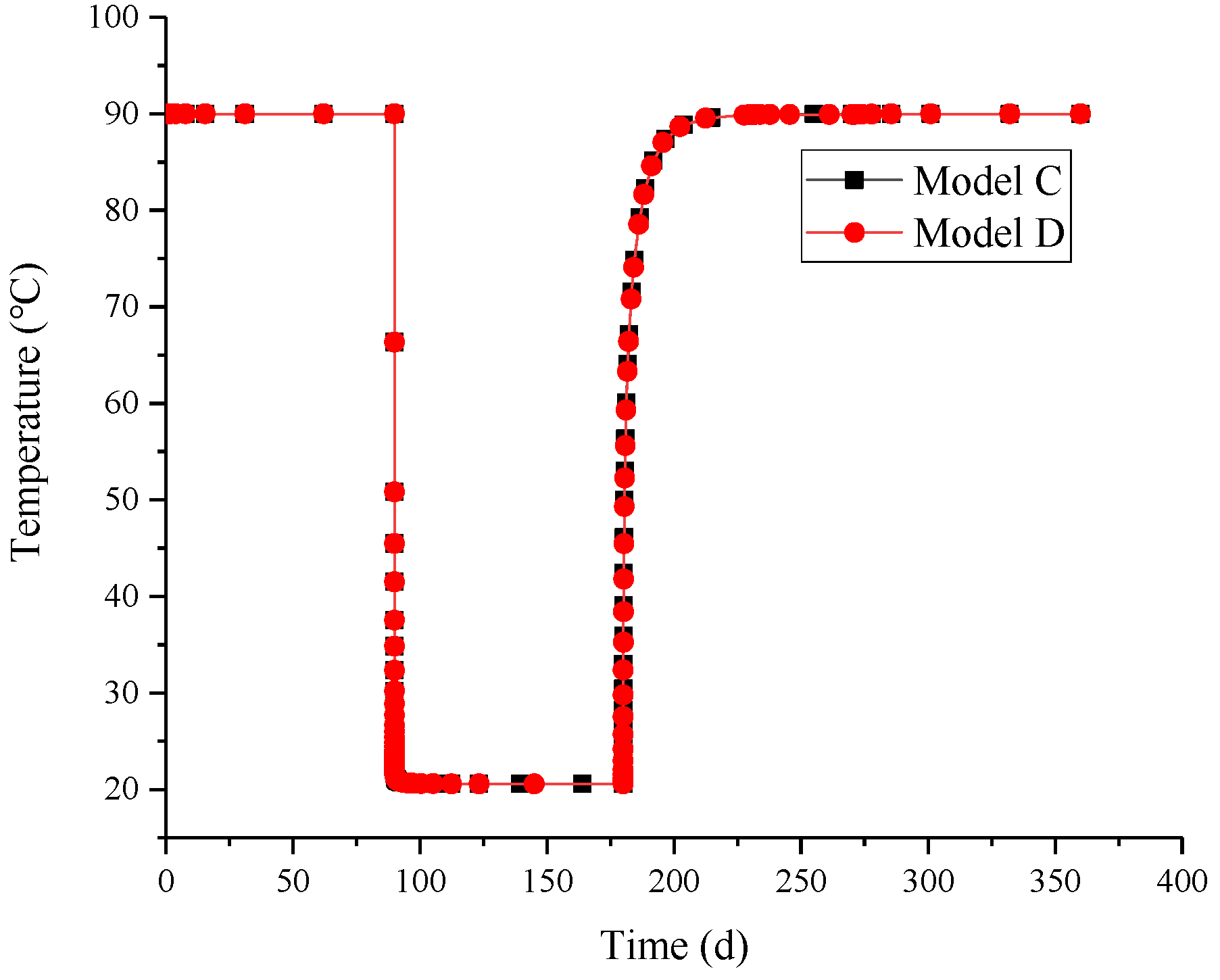
During one complete UGS operational cycle, the temperature of the cement sheath’s inner wall (CSIW) of Model C and Model D varies over time, as depicted in Figure 10. The temperature curves of the CSIW of Model C and Model D overlap approximately, showing that the formation creep has almost no influence on the cement sheath’s temperature. During the constant low pressure stage, the cement sheath’s temperature remains constant. During the pressurized gas injection stage, the temperature of the cement sheath rapidly decreases and then stabilizes. During the constant high pressure stage, the cement sheath’s temperature gradually recovers and subsequently reaches a stable state. During the depressurization gas production stage, the cement sheath’s temperature remains unchanged.
The Von Mises stress on the CSIW of different models fluctuates over time during the operation of the UGS for one cycle, as illustrated in Figure 11. As depicted in Figure 11a, during the operation of UGS, the Von Mises stress on the CSIW for the four models remains below the cement sheath’s compressive strength, indicating that the cement sheath of the four models did not occur shear failure. The order of maximum Von Mises stress on the CSIW for the four models is Model D > Model C > Model B > Model A, which indicates that Model D carries the highest risk of the cement sheath’s shear failure. Combining Figure 9 and Figure 11b, it is evident that formation creep leads to an elevation in Von Mises stress on the CSIW during the constant low pressure stage. Subsequently, as the Von Mises stress on the formation’s inner wall decreases and reaches a stable state, the ability of formation creep weakens, leading to a gradually stabilization of the Von Mises stress on the CSIW gradually stabilizes. Combining Figure 10 and Figure 11c, it is evident that during the initial stage of pressurized gas injection, there is a swift decline in the temperature of the CSIW, leading to a pronounced surge in Von Mises stress on the CSIW. Subsequently, the temperature of the CSIW stabilizes, while the casing internal pressure gradually increases, consequently causing a sustained elevation in the Von Mises stress on the CSIW. During the constant high pressure stage, the temperature of the CSIW gradually increases and then stabilizes. Consequently, the Von Mises stress on the CSIW gradually decreases and then stabilizes. Combining Figure 11d with Figure 9 and Figure 10, it can be seen that the formation creep that occurs during the constant low pressure stage causes the Von Mises stress on the CSIW to first increase and then stabilize. Moreover, the cement sheath’s temperature during the pressurized gas injection stage decreases, causing an increase in Von Mises on the CSIW. Therefore, among the four models, Model D exhibits the highest Von Mises stress on the CSIW.
The circumferential stress on the CSIW of different models fluctuates over time during a complete cycle of UGS operation, as illustrated in Figure 12. As depicted in Figure 12a, the circumferential stresses in all four models remain negative (indicating compressive stress) and are below the cement sheath’s tensile strength. This observation implies that the cement sheath of the four models does not occur circumferential tensile failure. Among the four models, the maximum circumferential stress on the CSIW follows this order: Model C > Model D > Model A > Model B. This ranking indicates that Model C presents the greatest risk of the cement sheath’s tensile failure. As depicted in Figure 12b, during the constant low pressure stage, formation creep induces a 0.7 MPa increase in the circumferential compressive stress on the CSIW. Conversely, in Figure 12c, during the pressurized gas injection stage, the temperature of the cement sheath decreases, leading to a reduction of 7.8 MPa in circumferential compressive stress on the CSIW. Consequently, Figure 12d shows a decrease in the maximum circumferential compressive stress on the CSIW.
The radial stress on the CSIW of different models varies over time during a complete cycle of UGS operation, as illustrated in Figure 13. As depicted in Figure 13a, the radial stresses in all four models are all negative (indicating compressive stress), showing the absence of debonding failure in the cement sheaths of these models. The maximum radial stress on the CSIW follows this order for the four models: Model C > Model A > Model D > Model B. Figure 13b shows that the formation creep increases the radial compressive stress on the CSIW. In Figure 13c, during the pressurized gas injection stage, the temperature of the cement sheath decreases, resulting in decreased radial compressive stress on the CSIW. Conversely, during the constant high pressure stage, the temperature increase in the cement sheath elevates the radial compressive stress on the CSIW. Figure 13d shows that the combined influence of formation creep and temperature changes in the cement sheath leads to an increase in the radial compressive stress on the CSIW.
To summarize, the Von Mises stress on the CSIW reaches its peak under the combined effect of formation creep and downhole temperature changes, consequently posing the highest risk of shear failure for the cement sheath. The circumferential compressive stress on the CSIW is the lowest under the influence of underground temperature changes, thus elevating the risk of tensile failure for the cement sheath.

3.3. The Influence of the Upper Limit of Operating Pressure of UGS on the Integrity of Cement Sheath

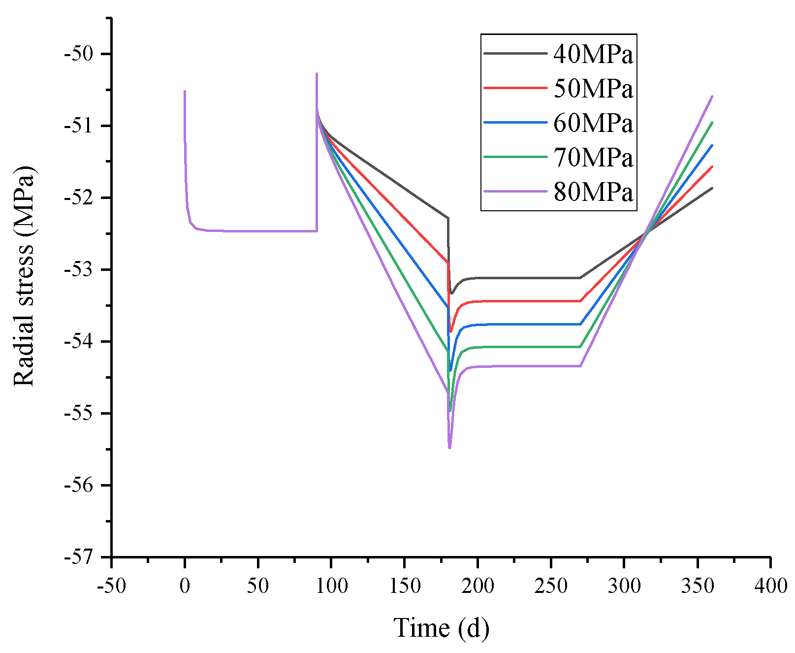
Considering the comprehensive effect of formation creep and downhole temperature changes, while keeping other parameters constant, the impact of the upper limit of operating pressure on the CSI is investigated. Figure 14 illustrates the Von Mises stress and PEEQ on the CSIW with the different upper limits of operating pressure during a complete cycle of UGS operation. As depicted in Figure 14, the higher the upper limit of operating pressure, the greater the maximum Von Mises stress and PEEQ on the CSIW. Notably, the Von Mises stress on the CSIW reached the cement sheath’s compressive strength at upper operating pressure limits of 70 MPa and 80 MPa, leading to shear failure for the cement sheath. The variation of circumferential stress on the CSIW with the different upper limits of operating pressure over time is illustrated in Figure 15, and the variation of radial stress over time is illustrated in Figure 16. The circumferential stress on the CSIW with different upper operating pressure limits are all circumferential compressive stresses, and the tensile failure for the cement sheath is not observed. Likewise, the radial stresses on the CSIW with different upper operating pressure limits are all radial compressive stresses, and the debonding failure for the cement sheath is not observed. In summary, under the high upper limit of operating pressure conditions, the CSI will fail in the form of shear failure. Therefore, to guarantee the safe and efficient operation of UGS, the upper limit of operating pressure should be controlled to not exceed 70 MPa.

3.4. Measure to Prevent the Integrity Failure of Cement Sheath

From the perspective of regulating the cement sheath’s elastic modulus to prevent the cement sheath’s shear failure during the operation of UGS under the combined effects of formation creep and downhole temperature changes, considering the formation creep and downhole temperature changes, the upper limit of the operating pressure is 80 MPa, keeping all other parameters unchanged. The UGS is operated for one cycle, and the cement sheath’s elastic modulus varies at 3 GPa, 6 GPa, 9 GPa, 12 GPa, and 15 GPa, respectively. We investigate how the cement sheath’s elastic modulus influences its susceptibility to shear failure. After one cycle of operation of the UGS, Figure 17 shows the PEEQ cloud diagrams of the cement sheath with different elastic moduli. As depicted in Figure 17, a higher elastic modulus corresponds to a larger PEEQ in the cement sheath and a greater extent of failure area. When the elastic modulus is 3 GPa, the PEEQ of the cement sheath registers at 0, indicating the absence of shear failure.
The Von Mises stress and PEEQ on the CSIW with different elastic moduli vary over time during the operation of the UGS for one cycle, as illustrated in Figure 18. In Figure 18, increasing the cement sheath’s elastic modulus results in higher Von Mises stress and PEEQ on its inner wall. A higher cement sheath’s elastic modulus leads to an earlier attainment of Von Mises stress, approaching the cement sheath elastic modulus inner wall, thus resulting in quicker PEEQ generation and earlier onset of cement sheath shear failure. In summary, reducing the cement sheath’s elastic modulus can maintain the CSI during the operation of the UGS.

4. Conclusions

This study performs creep experiments on salt rock to acquire the steady-state creep rate of salt rock across different temperatures and deviatoric stress levels. Experimental data are fitted to obtain the hyperbolic sine law mode for salt rock creep, reflecting the influence of temperature and deviatoric stress on the steady-state creep rate. Using the salt rock creep model as a foundation, an FEM model of the casing–cement sheath–creep formation assembly was developed in ABAQUS to study the effects of formation creep, temperature changes, and the upper limit of operating pressure on the CSI. The results demonstrate that both formation creep and a decrease in the cement sheath’s temperature increase the cement sheath’s Von Mises stress, consequently elevating the risk of shear failure. Reduced cement sheath temperature, conversely, diminishes circumferential compressive stress in the cement sheath, thereby elevating the risk of tensile failure. Under a high upper limit of operating pressure, shear failure manifests within the cement sheath. A higher cement sheath’s elastic modulus leads to increased maximum Von Mises stress, larger shear failure area, and higher PEEQ values. Lowering the cement sheath’s elastic modulus and limiting operating pressure can maintain the CSI under the combined effect of formation creep and downhole temperature changes during the operation of the UGS.

Author Contributions

Conceptualization, methodology and writing—original draft preparation, H.Y.; resources and supervision, Y.B.; investigation and validation, S.J.; visualization and data curation, S.G.; writing—reviewing and editing and formal analysis, H.L. All authors have read and agreed to the published version of the manuscript.

Funding

This work was funded by the National Natural Science Foundation of China [51974355].

Data Availability Statement

Not applicable.

Conflicts of Interest

The authors declare no conflict of interest.

Abbreviations

Finite element method (FEM); equivalent plastic strain (PEEQ); underground gas storage (UGS); cement sheath integrity (CSI); cement sheath inner wall (CSIW).

References

  1. Yang, C.; Daemen, J.J.K.; Yin, J.H. Experimental investigation of creep behavior of salt rock. Int. J. Rock Mech. Min. Sci. 1999, 36, 233–242. [Google Scholar] [CrossRef]
  2. Yang, H.; Bu, Y.; Guo, S.; Liu, H.; Du, J.; Cao, X. Effects of in-situ stress and elastic parameters of cement sheath in salt rock formation of underground gas storage on seal integrity of cement sheath. Eng. Fail. Anal. 2021, 123, 105258. [Google Scholar] [CrossRef]
  3. Yin, F.; Hou, D.; Liu, W.; Deng, Y. Novel assessment and countermeasure for micro-annulus initiation of cement sheath during injection/fracturing. Fuel 2019, 252, 157–163. [Google Scholar] [CrossRef]
  4. Bu, Y.; Du, J.; Guo, S.; Liu, H.; Liang, Y.; Su, Z.; Li, Y. Effects of formation water influx on the bonding strength between oil well cement and the formation. Constr. Build. Mater. 2020, 251, 118989. [Google Scholar] [CrossRef]
  5. De Andrade, J.; Sangesland, S. Cement Sheath Failure Mechanisms: Numerical Estimates to Design for Long-Term Well Integrity. J. Pet. Sci. Eng. 2016, 147, 682–698. [Google Scholar] [CrossRef]
  6. Bu, Y.; Yang, H.; Zhao, L.; Guo, S.; Liu, H.; Ma, X. Stress concentration of perforated cement sheath and the effect of cement sheath elastic parameters on its integrity failure during shale gas fracturing. Front. Mater. 2022, 9, 980920. [Google Scholar] [CrossRef]
  7. He, T.; Wang, T.; Wang, D.; Xie, D.; Daemen, J. Failure mechanism of gas storage salt cavern cement sheath under the coupling effect of plasticity and fatigue damage. Constr. Build. Mater. 2022, 354, 129179. [Google Scholar] [CrossRef]
  8. Zhao, L.; Yang, H.; Wei, Y.; Bu, Y.; Jing, S.; Zhou, P. Integrity and Failure Analysis of Cement Sheath Subjected to Coalbed Methane Fracturing. Fluid Dyn. Mater. Process. 2023, 19, 329–344. [Google Scholar] [CrossRef]
  9. Jandhyala, S.R.K.; Barhate, Y.R.; Anjos, J.; Fonseca, C.E.; Ravi, K. Cement Sheath Integrity in Fast Creeping Salts: Effect of Well Operations. In Proceedings of the SPE Offshore Europe Oil and Gas Conference and Exhibition, Aberdeen, UK, 3–6 September 2013; Society of Petroleum Engineers: Alexandria, VA, USA. [Google Scholar] [CrossRef]
  10. Tian, L.; Bu, Y.; Liu, H.; Lu, C.; Guo, S.; Xu, H.; Ren, Y. Effects of the mechanical properties of a cement sheath and formation on the sealing integrity of the cement-formation interface in shallow water flow in deep water. Constr. Build. Mater. 2023, 369, 130496. [Google Scholar] [CrossRef]
  11. Zhou, S.; Liu, R.; Zeng, H.; Zeng, Y.; Zhang, L.; Zhang, J.; Li, X. Mechanical characteristics of well cement under cyclic loading and its influence on the integrity of shale gas wellbores. Fuel 2019, 250, 132–143. [Google Scholar] [CrossRef]
  12. Li, C.; Guan, Z.; Zhao, X.; Yan, Y.; Zhang, B.; Wang, Q.; Sheng, Y. A new method to protect the cementing sealing integrity of carbon dioxide geological storage well: An experiment and mechanism study. Eng. Fract. Mech. 2020, 236, 107213. [Google Scholar] [CrossRef]
  13. Yang, H.; Bu, Y.; Jing, S.; Guo, S.; Liu, H. Adaptability of Different Shear Failure Criteria in Shear Failure Evaluation of Cement Sheaths. Arab. J. Sci. Eng. 2023, 1–10. [Google Scholar] [CrossRef]
  14. Patel, H.; Salehi, S. Development of an Advanced Finite Element Model and Parametric Study to Evaluate Cement Sheath Barrier. J. Energy Resour. Technol.-Trans. ASME 2019, 141, 092902. [Google Scholar] [CrossRef]
  15. Patel, H.; Salehi, S. Structural integrity of liner cement in oil & gas wells: Parametric study, sensitivity analysis, and risk assessment. Eng. Fail. Anal. 2021, 122, 105203. [Google Scholar] [CrossRef]
  16. Zhang, H.; Shen, R.; Yuan, G.; Ba, Z.; Hu, Y. Cement sheath integrity analysis of underground gas storage well based on elastoplastic theory. J. Pet. Sci. Eng. 2017, 159, 818–829. [Google Scholar] [CrossRef]
  17. Yan, X.; Jun, L.; Gonghui, L.; Qian, T.; Wei, L. A new numerical investigation of cement sheath integrity during multistage hydraulic fracturing shale gas wells. J. Nat. Gas Sci. Eng. 2018, 49, 331–341. [Google Scholar] [CrossRef]
  18. Liu, K.; Gao, D.; Zeng, J.; Wang, Z. Study on Cement Sheath Integrity in Horizontal Wells during Hydraulic Fracturing Process. In Proceedings of the 52nd U.S. Rock Mechanics/Geomechanics Symposium, Seattle, WA, USA, 17–20 June 2018. [Google Scholar]
  19. Bagheri, M.; Shariatipour, S.M.; Ganjian, E. Parametric study on the integrity of wellbores in CO2 storage sites. Constr. Build. Mater. 2021, 268, 121060. [Google Scholar] [CrossRef]
  20. Liu, K.; Gao, D.; Taleghani, A.D. Analysis on integrity of cement sheath in the vertical section of wells during hydraulic fracturing. J. Pet. Sci. Eng. 2018, 168, 370–379. [Google Scholar] [CrossRef]
  21. Guo, S.; Bu, Y.; Yang, X.; Wang, C.; Guo, B.; Sun, B. Effect of casing internal pressure on integrity of cement ring in marine shallow formation based on XFEM. Eng. Fail. Anal. 2020, 108, 104258. [Google Scholar] [CrossRef]
  22. Han, X.; Feng, F.; Zhang, J. Study on the whole life cycle integrity of cement interface in heavy oil thermal recovery well under circulating high temperature condition. Energy 2023, 278, 127873. [Google Scholar] [CrossRef]
  23. Chu, W.; Shen, J.; Yang, Y.; Li, Y.; Gao, D. Calculation of micro-annulus size in casing-cement sheath-formation system under continuous internal casing pressure change. Pet. Explor. Dev. 2015, 42, 414–421. [Google Scholar] [CrossRef]
  24. Bu, Y.; Tian, L.; Guo, B.; Wang, C.; Sun, B. Experiment and simulation on the integrity of cement ring interface in deep water shallow formation. J. Pet. Sci. Eng. 2020, 190, 107127. [Google Scholar] [CrossRef]
  25. Liu, X.; Birchwood, R.; Hooyman, P.J. A new analytical solution for wellbore creep in soft sediments and salt. In Proceedings of the 45th U.S. Rock Mechanics/Geomechanics Symposium, San Francisco, CA, USA, 26–29 June 2011; American Rock Mechanics Association: Alexandria, VA, USA, 2011. [Google Scholar]
  26. Orlic, B.; Buijze, L. Numerical modeling of wellbore closure by the creep of rock salt caprocks. In Proceedings of the 48th U.S. Rock Mechanics/Geomechanics Symposium, Minneapolis, MN, USA, 1–4 June 2014; American Rock Mechanics Association: Alexandria, VA, USA, 2014. [Google Scholar]
  27. Orlic, B.; Thienen-Visser, V.; Schreppers, G. Numerical estimation of structural integrity of salt cavern wells. In Proceedings of the 50th US Rock Mechanics/Geomechanics Symposium, Houston, TX, USA, 26–29 June 2016; American Rock Mechanics Association: Alexandria, VA, USA, 2016. [Google Scholar]
  28. Melo, D.; Fountoura, S.A.B.; Inoue, N.; Anjos, J.L.R. Finite Element Analysis of Casing-in-Casing Integrity due to Annulus Pressurization by means of Salt Creep. In Proceedings of the 49th US Rock Mechanics/Geomechanics Symposium, San Francisco, CA, USA, 28 June–1 July 2015; American Rock Mechanics Association: Alexandria, VA, USA, 2015. [Google Scholar]
  29. Yu, B.; Hardy, M.P.; Zhao, H. Laboratory Testing of Casing-Cement Interface and Multi-Scale Modeling of Casing Integrity Within Salt. In Proceedings of the 51st US Rock Mechanics/Geomechanics Symposium, San Francisco, CA, USA, 25–28 June 2017; American Rock Mechanics Association: Alexandria, VA, USA, 2017. [Google Scholar]
  30. Velilla, J.; Fountoura, S.A.B.; Inoue, N.; Anjos, J.L.R. Numerical modelling of casing integrity in salt layers including the effects of dissolution and creep. In Proceedings of the 49th US Rock Mechanics/Geomechanics Symposium, San Francisco, CA, USA, 28 June–1 July 2015; American Rock Mechanics Association: Alexandria, VA, USA, 2015. [Google Scholar]
  31. Gholami, R.; Aadnoy, B.; Fakhari, N. A thermo-poroelastic analytical approach to evaluate cement sheath integrity in deep vertical wells. J. Pet. Sci. Eng. 2016, 147, 536–546. [Google Scholar] [CrossRef]
  32. Jenab, A.; Taheri, A.K.; Jenab, K. The Use of ANN to Predict the Hot Deformation Behavior of AA7075 at Low Strain Rates. J. Mater. Eng. Perform. 2013, 22, 903–910. [Google Scholar] [CrossRef]
  33. Erisov, Y.; Surudin, S.; Grechnikov, F. Hot Deformation Behavior of Al-Cu-Li-Mg-Zn-Zr-Sc Alloy in As-Cast and Hot-Rolled Condition. Mater. Sci. Forum 2018, 920, 244–249. [Google Scholar] [CrossRef]
  34. Maia, C.A.; Poiate, E., Jr.; Falcao, J.L.; Coelho, L.F.M. Triaxial Creep Tests in Salt Applied in Drilling Through Thick Salt Layers in Campos Basin-Brazil. In Proceedings of the SPE/IADC Drilling Conference, Amsterdam, The Netherlands, 23–25 February 2005. [Google Scholar]
  35. Poiate, E., Jr.; Costa, A.M.; Falcao, J.L. Well Design for Drilling Through Thick Evaporite Layers in Santos Basin—Brazil. In Proceedings of the IADC/SPE Drilling Conference, Miami, FL, USA, 21–23 February 2006. [Google Scholar]
  36. da Costa, A.; Amaral, C.; Poiate, E.; Pereira, A.; Martha, L.; Gattass, M.; Roehl, D. Underground storage of natural gas and CO2 in salt caverns in deep and ultra-deep water offshore Brazil. In Proceedings of the 12th ISRM Congress, Beijing, China, 16–21 October 2011; pp. 1659–1664. [Google Scholar] [CrossRef]
  37. Costa, A.M.; Roehl, D.; da Costa, A.M.; Amaral, C.d.S.; Poiate, E., Jr. Rock Mechanics and Computer Modeling Applied in the Design of Underground Salt Caverns Opened by Solution Mining for Brine Production and Natural Gas Storage. In Proceedings of the 13th ISRM International Congress of Rock Mechanics, Montreal, QC, Canada, 10–13 May 2015. [Google Scholar]
  38. Da Costa, A.M.; Costa, P.V.M.; Miranda, A.C.O.; Goulart, M.B.R.; Bergsten, A.; Meneghini, J.R.; Nishimoto, K.; Assi, G.R.S.; Sampaio, C.M.; Ebecken, N.F.F.; et al. Well Design for the Construction and Operation of an Experimental Salt Cavern Built Offshore in Ultra-Deep Water for CCS in Brasil. In Proceedings of the 54th U.S. Rock Mechanics/Geomechanics Symposium, Physical Event Cancelled, 28 June–1 July 2020. [Google Scholar]
  39. Fan, M.; Liu, G.; Li, J.; Guo, L.; He, M.; Li, B. Study on Micro-gap Generation Mechanism of Cement Ring Interface Under Thermal Alternating Pressure. Sci. Technol. Eng. 2016, 16, 72–76. [Google Scholar]
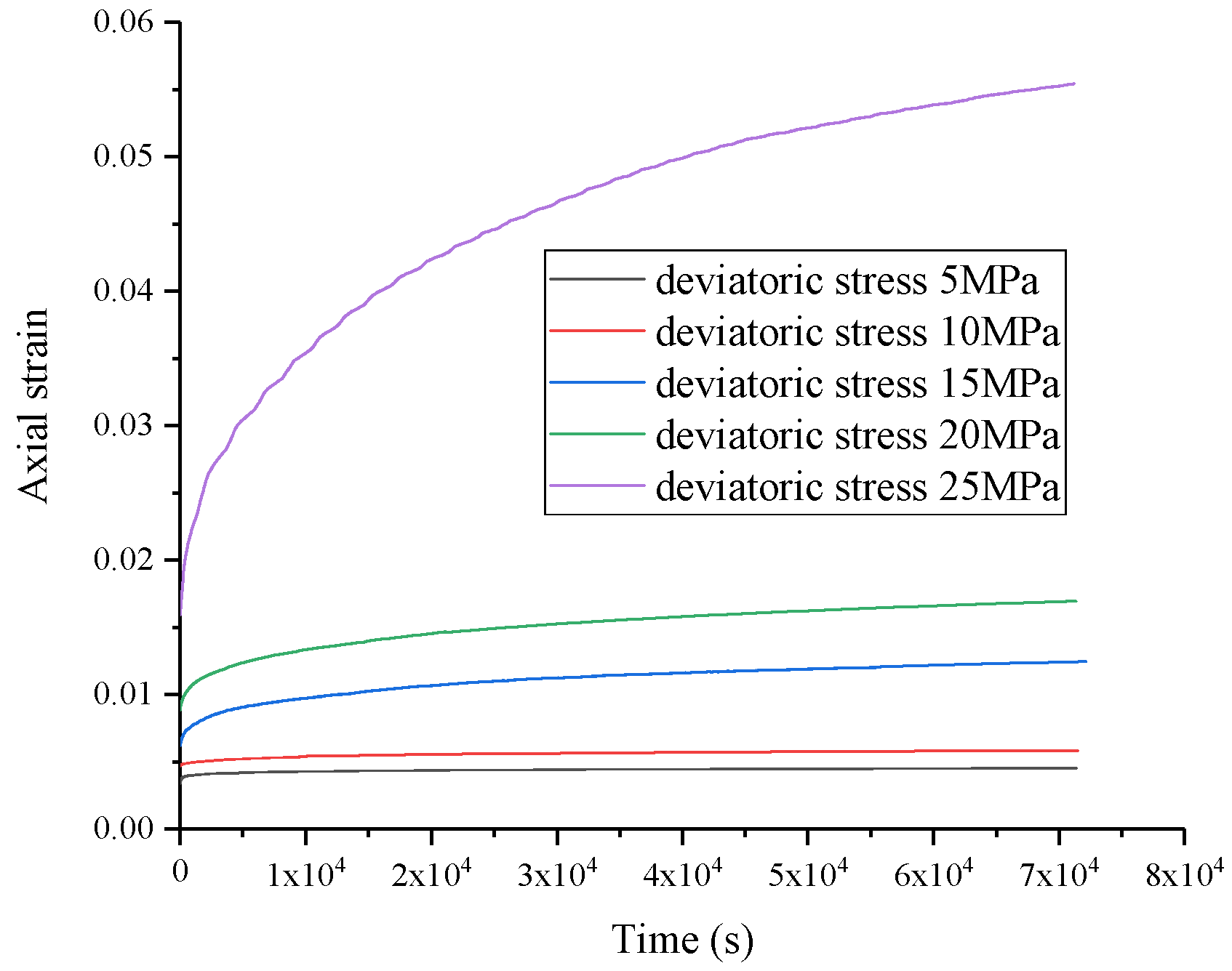
Figure 1. Creep curves of salt rock at varying deviatoric stresses.
Energies 16 07089 g001
Figure 2. Creep curves of salt rock at varying temperatures.
Energies 16 07089 g002
Figure 3. FEM model for creep simulation.
Energies 16 07089 g003
Figure 4. Steady-state creep rate of salt rock at varying temperatures and pressure loads.
Energies 16 07089 g004
Figure 5. FEM model of casing–cement sheath–creep formation combination.
Energies 16 07089 g005
Figure 6. Change of casing internal pressure during one cycle of UGS operation.
Energies 16 07089 g006
Figure 7. Temperature variation of formation inner wall of UGS during one cycle of operation without formation creep.
Energies 16 07089 g007
Figure 8. Von Mises stress variation of formation inner wall of UGS during one cycle of operation without formation creep.
Energies 16 07089 g008
Figure 9. Comparison of Von Mises stress of formation inner wall with and without formation creep.
Energies 16 07089 g009
Figure 10. Variation of temperature on the CSIW with time for diverse models.
Energies 16 07089 g010
Figure 11. Variation of Von Mises stress on the CSIW with time for different models. (a) comparison of all models; (b) comparison between Model A and Model B; (c) comparison between Model A and Model C; (d) comparison between Model A and Model D.
Energies 16 07089 g011
Figure 12. Variation of circumferential stress on the CSIW with time for four models: (a) comparison of all models; (b) comparison between Model A and Model B; (c) comparison between Model A and Model C; (d) comparison between Model A and Model D.
Energies 16 07089 g012
Figure 13. Variation of radial stress on the CSIW with time for four models: (a) comparison of all models; (b) comparison between Model A and Model B; (c) comparison between Model A and Model C; (d) comparison between Model A and Model D.
Energies 16 07089 g013
Figure 14. Variation of Von Mises stress and PEEQ on the CSIW with time for different upper limit of operating pressure: (a) Von Mises stress; (b) PEEQ.
Energies 16 07089 g014
Figure 15. Variation of circumferential stress on the CSIW with time for different upper limit of operating pressure.
Energies 16 07089 g015
Figure 16. Variation of radial stress on the CSIW with time for different upper limit of operating pressure.
Energies 16 07089 g016
Figure 17. PEEQ cloud diagrams of cement sheath with different cement sheath elastic moduli: (a) 3 GPa; (b) 6 GPa; (c) 9 GPa; (d) 12 GPa; (e) 15 GPa.
Energies 16 07089 g017
Figure 18. Variation of Von Mises stress and PEEQ on the CSIW with time for different cement sheath elastic moduli: (a) Von Mises stress; (b) PEEQ.
Energies 16 07089 g018
Table 1. Temperature and pressure loads in salt rock creep experiments.
Sample NumberConfine Pressure/MPaAxial Pressure/MPaDeviatoric Stress/MPaTemperature/°C
15302524
210302024
315301524
420301024
52530524
615301550
715301570
815301590
Table 2. Steady-state creep rates for diverse samples.
Sample NumberSteady-State Creep Rate/s−1
11.782 × 10⁻⁷
21.192 × 10⁻⁷
34.199 × 10⁻⁸
43.687 × 10⁻⁸
52.543 × 10⁻⁹
66.655 × 10⁻⁸
73.753 × 10⁻⁷
88.534 × 10⁻⁶
Table 3. Model geometric parameters [2].
MaterialInner Diameter/mmOuter Diameter/mm
Casing247.94282.58
Cement sheath282.58320
Formation3203200 × 3200
Table 4. Physical property parameters of the model [2,39].
MaterialElastic
Modulus/GPa
Poisson’s RatioDensity/(kg·m−3)Coefficient of Expansion
/10−5 °C−1
Specific Heat/
(J kg−1·°C−1)
Thermal Conductivity/
(W·m−1·°C−1)
Casing2100.378001.2246045
Cement sheath10.610.2218001.058650.9
Formation1.800.3823001.038962.2
Table 5. Comparison of different models.
ModelFormation CreepDownhole Temperature Change
Model A××
Model B×
Model C×
Model D
Disclaimer/Publisher’s Note: The statements, opinions and data contained in all publications are solely those of the individual author(s) and contributor(s) and not of MDPI and/or the editor(s). MDPI and/or the editor(s) disclaim responsibility for any injury to people or property resulting from any ideas, methods, instructions or products referred to in the content.