Article

Self- and Mutual-Inductance Cross-Validation of Multi-Turn, Multi-Layer Square Coils for Dynamic Wireless Charging of Electric Vehicles

by
Mincui Liang
*,
Khalil El Khamlichi Drissi
and
Christopher Pasquier
Institut Pascal, CNRS, Clermont Auvergne INP, Université Clermont Auvergne, F-63000 Clermont-Ferrand, France
*
Author to whom correspondence should be addressed.
Energies 2023, 16(20), 7033; https://doi.org/10.3390/en16207033
Submission received: 20 September 2023 / Revised: 4 October 2023 / Accepted: 9 October 2023 / Published: 10 October 2023
(This article belongs to the Section E: Electric Vehicles)

Abstract

:
Dynamic Wireless Power Transfer (DWPT) has high potential to overcome electric vehicles’ battery issues of size and range and to achieve fully autonomous driving. Accurately extracting the self- and mutual-inductance of the coils is essential for controlling and optimizing the overall performance of the DWPT system under real driving conditions. Due to the limited space for coil installation at the bottom of the vehicles, multi-turn, multi-layer square coils are proposed to maximize the space utilization of the DWPT system. For the first time, this paper presents a theoretical model for calculating the self- and mutual-inductance and the coupling coefficients of multi-turn, multi-layer square coils. Taking a four-turn, four-layer square coil as an example, the model is cross-validated by 3D coil modelling and simulation, as well as practical measurements. A theoretical–experimental verification is further conducted to indirectly corroborate the cross-validated coupling coefficients of the two coils. On average, the normalized root mean square errors of the resultant self-inductance and coupling coefficients of two identical coils are 1.04 % and 4.29 % , respectively. Specifically, for the selected case, normalized root mean square errors of the zero-phase angle frequencies of the system under different misalignment situations average out at 1.32 % .

1. Introduction

The concept of resonance wireless power transfer (WPT) was first proposed by Nicola Tesla and later patented in the early twentieth century [1]. Since then, it has been studied and developed further into an important branch of wireless charging, and applied in different near-field charging applications, such as implantable devices in bio-engineering [2,3], 3D integrated circuits [4], mobile devices [5,6], Internet of Things (IoT) devices [7], mobility devices [8] and even powering multiple home appliances [9]. Specifically, after a group of researchers from the Massachusetts Institute of Technology demonstrated the improved efficiency of the resonance coupling WPT [10,11,12], its potential and applications in static and dynamic wireless charging of electric vehicles (EVs) have been widely investigated [13,14,15,16,17]. Potentially, dynamic wireless power transfer (DWPT) can help achieve truly autonomous driving without restriction. Although the feature of driving freely is tempting, the coupling coefficient of the DWPT system changes over time and the control of the system becomes challenging under dynamic conditions [18]. Hence, thoroughly understanding the self- and mutual-inductance is of vital importance for gaining a deeper understanding of its natural phenomenon and laying a theoretical foundation for studying mutual inductance and coupling coefficients between two coils under different misalignment situations in the DWPT systems.
The self- and mutual-inductance calculation depends essentially on the coil geometry. Two common shapes of the EV’s WPT coils are circular and rectangular/square [19,20,21]. Most of the studies focus on circular coils [22] and single-layer coils [23]. However, rectangular/square coils are more tolerant towards the misalignment between coils, which makes them more favourable for DWPT applications [24,25]. Furthermore, square coils are advantageous in terms of space utilization rate and area maximization with the same wire length compared to rectangular coils. This can potentially lead to much less copper consumption when practically building the DWPT charging infrastructure, which is a huge advantage since cost is one of the obstacles to DWPT’s uptake in EV applications. Although the square coil’s coupling coefficient is low, it can still achieve maximum power and high efficiency by optimal frequency control for each given coupling coefficient [26], instead of coil structure design optimization by adding ferrite materials [27]. To optimize the power transfer of the DWPT system, it is critical to obtain an accurate theoretical model of the DWPT system, where the coupling coefficient is the key parameter.
In this paper, we created four-turn, four-layer square coils for the DWPT system and developed a set of mathematical formulas to determine the self- and mutual-inductance as well as the coupling coefficients of multi-turn, multi-layer square coils. We used the finite element method and two practical measurement techniques to cross-validate our findings. Finally, we incorporated the validated coupling coefficients into the theoretical model of the DWPT system to calculate the Zero Phase Angle (ZPA) frequencies and compared them with the frequencies obtained from the experiment. This approach ensures the accuracy of the coupling coefficient of the multi-turn, multi-layer square coil.
The rest of the paper is organized as follows. Section 2 gives a brief introduction to one multi-turn, multi-layer square coil. Section 3 develops a detailed theoretical model of the self- and mutual-inductance of the multi-turn, multi-layer square coil, and the coupling coefficients between two identical square coils. Section 4 provides a 3D finite-element modelling and simulation method to simulate the magnetic flux distribution, calculate the self-inductance of the coil and estimate the mutual inductance and coupling coefficients of the square coils. Section 5 further reports the measured results of the self- and mutual-inductance and coupling coefficients of the square coils, conducted using two common measuring methods. Section 6 provides a concise cross-validation of the three methods presented in Section 3, Section 4 and Section 5. In Section 7, theoretical–experimental verification is conducted to confirm the correctness of the self and mutual inductance and coupling coefficients of the coils cross-validated in Section 6. Finally, Section 8 concludes the paper with the achievements and gives suggestions for future studies.

2. A Multi-Turn, Multi-Layer Square Coil

According to an evaluation of the available surface area and self-inductance value of around 118 μ H for the experimental set-up, a four-turn, four-layer square coil was built. Figure 1 shows the detailed configuration and notations of this coil. These notations are also applied to a multi-turn, multi-layer square coil. The round winding wire has a diameter of ϕ = 3 mm, which is 0.04 % of its total length. Therefore, it is small enough to be considered an electric filament. The exterior dimension of the square coil, measured between two exterior round wires, is a = 253 mm. Similarly, the interior dimension equals 217 mm. In practice, the approximate geometric mean distance of two electric filaments, i.e., between the centres of their round cross sections, is used for calculating their mutual inductance [28]. Thus, the distance between two outer filaments of the coil is a 1 = 250 mm. The distance between two adjacent filaments in both vertical and horizontal directions is D = 5 mm. The straight section of each side of the coil, notated as b, is 130 mm in length. The exterior and interior corners of the coil have radii of 61.5 mm and 43.5 mm, respectively. Accordingly, the exterior and interior corners of the coil filaments have radii of R e x = 60 mm and R i n = 45 mm, respectively.
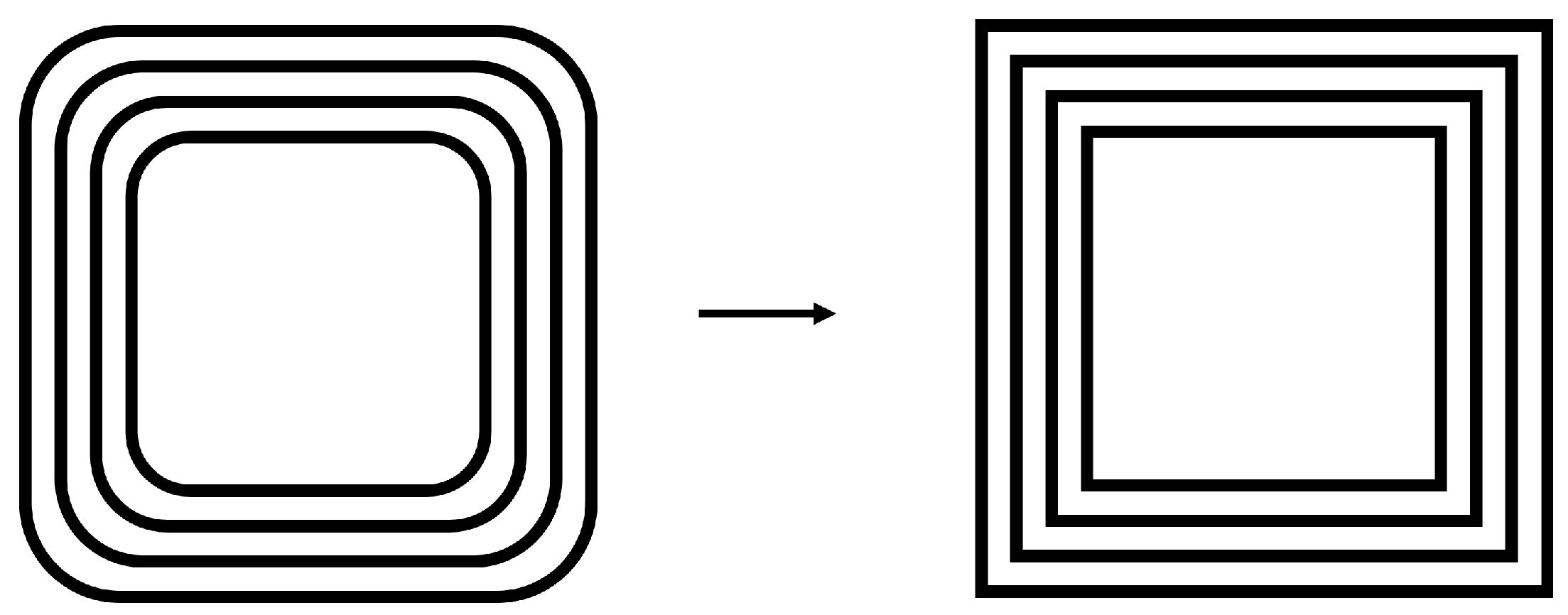
Practically, when constructing square coils using round wires, it is unavoidable to add fillets at the corners, which complicates the calculation of the coils’ self- and mutual-inductance. Therefore, for the ease of theoretical calculation, it is necessary to reconstruct the multi-turn, multi-layer square coil as an equivalent true square model of filaments with a slightly bigger surface area, shown in Figure 2.
For the convenience of theoretical calculation, Figure 3 gives a detailed illustration and notation of the equivalent filament coil from its top view and cross-section. The four sides of the coil, notated as s, are labelled 1 to 4 in a clockwise order, i.e., s [ 1 , 4 ] . x , y represent any two elements in s. From the horizontal cross-section drawing ( B B ) , the layer of the equivalent coil is notated as k and labelled 1 to P from top to bottom, i.e., k [ 1 , P ] , and m , n represent any two elements in k. P is the total number of layers. Similarly, the turn of filaments on one layer is notated as t and labelled 1 to N from outside to inside, i.e., t [ 1 , N ] , and i , j represent any two elements in t. N is the total number of turns on one layer.
Two random cross-section elements from two opposite sides, highlighted in red, demonstrate the relationship of the distance between two filaments of the coil given as
d i j m n = θ i j 2 + θ m n 2
where θ i j and θ m n are the horizontal and vertical distance between any two elements of the coil, respectively. i , j [ 1 , N ] and m , n [ 1 , P ] are the indexes of the turns and layers of the two filaments in question, respectively.
Furthermore, the length of one filament is notated as
l t k
where t indicates the t- t h turn, t [ 1 , N ] ; k indicates the k- t h layer, k [ 1 , P ] . When only one coil is concerned, side indication is not necessarily needed due to the square nature of the coil where all sides on one layer are of the same length.
However, if two coils are concerned when calculating their mutual inductance, a more specific notation of each parameter is necessary for distinguishing the coils, sides, layers, and turns of the filament pairs in question. In this case, the length of one filament according to its position is given as
l A s t k
where t, s, k and A indicate the t- t h turn, the s- t h side, the k- t h layer and the coil A, respectively.
Similarly, the distance between any two filaments of a coil A is given as
d A s i j m n
where i , j are the indexes of two turns from the N turns; m , n are the layer indexes of two filaments from the P layers.
The distance between one filament of a coil A and another filament of a coil B is notated as
d A x B y i j m n = d B y A x j i n m
where A x , B y represent the x- t h side filament of coil A and the y- t h side filament of coil B, respectively; i , j [ 1 , N ] are the indexes of the turns of the filament pair from coil A and coil B, respectively; m , n [ 1 , P ] are the layer indexes of the filament pair from coil A and coil B, respectively. For simplicity, the notations will be specified only where necessary in the rest of the paper.

3. Theoretical Calculation

Since Michael Faraday discovered the induction phenomena and James Clerk Maxwell formulated it mathematically [29] in the nineteenth century, many scholars have extended and applied them to the self- and mutual-inductance calculation to provide a simpler formula for various fundamental electrical circuits without dealing with surface integral [30]. These formulae can be carefully selected and used for more complicated coil geometry structures including multi-turn, multi-layer square coils. In this section, a mathematical formula is derived for calculating the self-inductance of the multi-turn, multi-layer square coil presented in Section 2, the mutual inductance and coupling coefficient of two identical square coils. For theoretical calculation, it is assumed that the coil is placed in the air without magnetic materials. Therefore, the inductance calculation depends only on the coil geometry and is independent of the current [28]. The formulae given for calculating the self- and mutual-inductance are for low-frequency situations since, when the total length of the wire is long enough, i.e., over 1000 times longer than the diameter of its cross-section, the change of inductance with frequency is negligible except for extremely high-precision needs [31].

3.1. Self Inductance

The self-inductance of the coil is equal to the summation of the self-inductance of each section of the filament and the mutual inductance of all paired combinations of filament sections which are used to compose the coil [28]. The formula for calculating the self-inductance of a straight filament in low frequency is given as [32]
L ( l , r ) = 0.002 [ l ln ( l + l 2 + r 2 r ) l 2 + r 2 + l 4 + r ]
where l and r are the length and radius of the filament in centimetres ( c m ), respectively. The unit of result is in microhenry ( μ H ).
The calculation of the mutual inductance between straight filament pairs depends on their geometric inter-relation since the relation of two current elements for producing mutual inductance is the dot product. Specifically, the mutual inductance is zero when the angle of two current elements is 90 . Therefore, the calculation only considers the mutual inductance of the filament pairs in parallel. The formula for calculating the mutual inductance of two parallel equal-length filaments in low frequency is given as [32]
M ( l , d ) = 0.002 [ l ln ( l + l 2 + d 2 d ) l 2 + d 2 + d ]
where l is the length of the filaments in centimetres (cm); d is the distance between two parallel filaments in centimetres (cm). The unit of result is in microhenry ( μ H ).
Due to the symmetric structure of the square coil, it is sufficient to separate it into four parts [33] to calculate only the self-inductance of one side of the coil and multiply it by four, shown as follows:
L c o i l = 4 × L o n e s i d e
The self-inductance of one side is calculated as
L o n e s i d e = L s e l f + M S S M O S
where L s e l f is the summation of the self-inductance of all filaments on one side. The calculation of mutual inductance involves two situations: (1) two filaments are on the same side and with the same current direction, which is called the Same Side (SS) situation; (2) two filaments are from opposite sides, i.e., one filament is from one side and the other filament is from its opposite side with an opposite current direction, which is called the Opposite Side (OS) situation. M S S is the summation of the mutual inductance of all filament pairs in the SS situation; M O S is the summation of the mutual inductance in the OS situation and its sign is negative, i.e., M o s , since the current flows in opposite directions in the parallel filaments.
The length of the filaments mainly depends on the ordinal number of turns, which is given as
l t k = a 1 2 × ( t 1 ) × D
where k represents the k- t h layer of the coil, k [ 1 , P ] , and t indicates the t- t h turn of the k- t h layer of the coil, t [ 1 , N ] .
Therefore, the self-inductance of one side of the coil, L s e l f , is calculated as
L s e l f = k = 1 P t = 1 N L ( l t k , r )
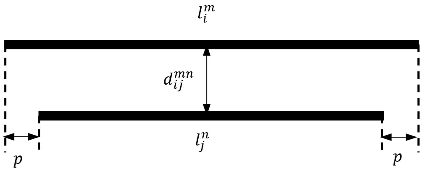
When calculating the mutual inductance of the coil, M S S and M O S , it involves both equal-length filament pairs and unequal-length filament pairs. The equal-length filament pairs have the same turn index t while the unequal-length filament pairs do not. Figure 4 provides an illustration of a parallel filament pair of unequal length, where two filaments are symmetrically arranged and the length difference between these two filaments is the same p at both ends.
In this case, the mutual inductance can be calculated as the combination of two re-arranged equal-length filaments, given as
M s e l f ( l , d , p ) = M ( l m i n + p , d ) M ( p , d )
where i , j are the turn indexes of any two elements; p is the one-end difference between two vertically centre-aligned filaments with unequal lengths; l m i n = min ( l i m , l j n ) . This formula holds true also for p = 0 when two filaments are of equal length.
As shown in (12), the main parameters are the distance between any two parallel filaments of the coil, d, and their lengths, l, calculated in (10). The distance is calculated differently for the SS situation and OS situation. The distance between two parallel filaments in the SS situation is given as
d S S i j m n = D × ( i j ) 2 + ( m n ) 2
The distance between two parallel filaments in the OS situation is calculated as
d O S i j m n = ( a 1 ( j + i 2 ) D ) 2 + ( m n ) 2 D 2
Therefore, the total mutual inductance in the SS situation, M S S , is calculated as
M S S = m , n = 1 P i , j = 1 ( i j , m = n ) N M s e l f ( min ( l i m , l j n ) , d S S i j m n , p )
The total mutual inductance in the OS situation, M O S , is calculated as
M O S = m , n = 1 P i , j = 1 N M s e l f ( min ( l i m , l j n ) , d O S i j m n , p )
To combine (1)–(16), the self inductance of an N-turn P-layer square coil is calculated as
L c o i l = 4 × ( L s e l f + M S S M O S )
Accordingly, as summarised in Table 1, the self-inductance of the four-turn, four-layer square coil, shown in Figure 1, is calculated to be 113.76   μ H .

3.2. Mutual-Inductance

The calculation of the mutual-inductance between two multi-turn, multi-layer square coils is the summation of the mutual inductance of all the filament pairs between two coils. It is similar to the mutual-inductance calculation in the self-inductance calculation Section 3.1 but the filament pairs are from two coils, instead of one coil. Therefore, full notations, created in the expressions (3)–(5), should be taken into use so as to specify the coil, side, layer, and turn of the selected filaments and avoid ambiguities during the calculation.
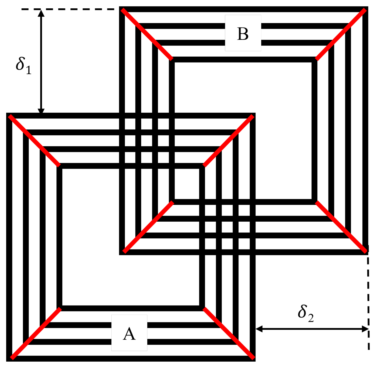
Misalignment between the primary coil and secondary coil is common in dynamic wireless charging systems and hence is of major concern for us when calculating their mutual inductance. Figure 5 shows one instance of misalignment with overlapping between two multi-turn, multi-layer square coils A and B. The vertical and horizontal misalignment between the two coils is δ 1 and δ 2 , respectively.
From a practical point of view, when calculating the mutual inductance between two coils, only the overlapping situations are considered, since when there is no overlapping between two coils, the mutual inductance is too low to transfer power. Considering an example shown in Figure 6, the filament pair consists of one filament of the coil A with a length of l A i m , and the other filament of the coil B with a length of l B j n . The distance between the two filaments is d A B i j m n and the overlapping length is Δ .
Following the special case of the unequal-length mutual-inductance calculation in Section 3.1, the mutual inductance of the filament pair in Figure 6 is the summation of the mutual inductance of four pairs of equal-length parallel filament segments, M o , given as [28]
M o ( l A i m , l B j n , d A B i j m n , Δ ) = 1 2 [ ( M α + M Δ ) ( M β + M γ ) ] M α = M ( l A i m + l B j n Δ , d A B i j m n ) M β = M ( l A i m Δ , d A B i j m n ) M γ = M ( l B j n Δ , d A B i j m n ) M Δ = M ( Δ , d A B i j m n )
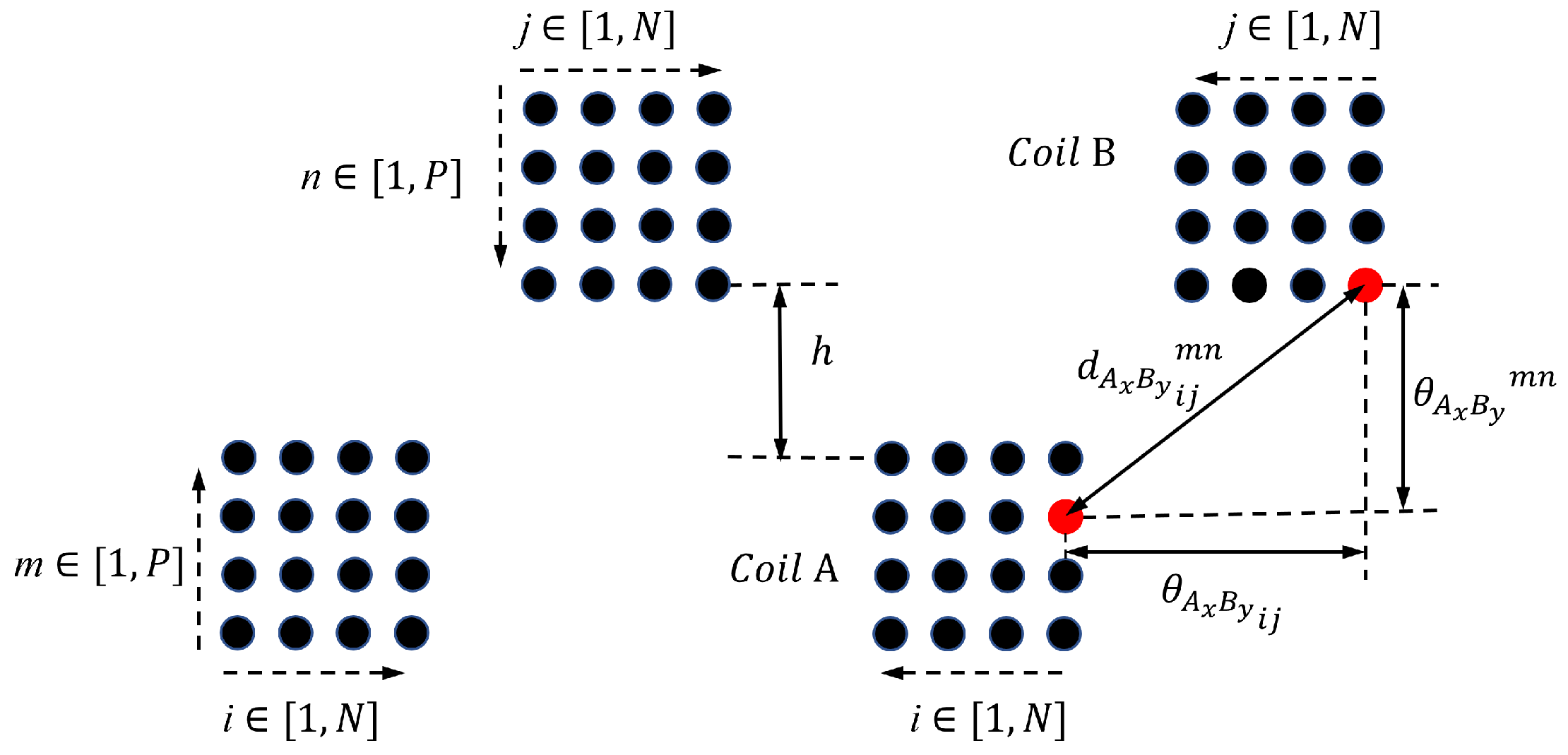
As a result of misalignment, the filament pairs between two coils A and B are practically asymmetric. Consequently, the calculation of the distance and overlapping length between the filament pair of the coils is much more complex. Specifically, two situations have to be considered when calculating Δ , and four situations have to be considered when calculating d A B i j m n . In order to calculate the distance between each parallel filament pair of coil A and coil B, we need first to obtain the vertical distance, θ A x B y m n , and the horizontal distance, θ A x B y i j , between these two filaments, as shown in Figure 7, which is a cross-section drawing of Figure 5. The diagonal distance, d A x B y i j m n , is the distance for mutual-inductance calculation. The top coil represents the coil B and the bottom coil is the coil A. There is a vertical distance, notated as h between two coils. The turns, i and j in coil A and coil B, separately, are notated from exterior to interior from 1 to N. The notation of layer, m in coil A and n in coil B are mirrored symmetry. m is counted from 1 to P from the bottom and n is labeled from 1 to P from the top.
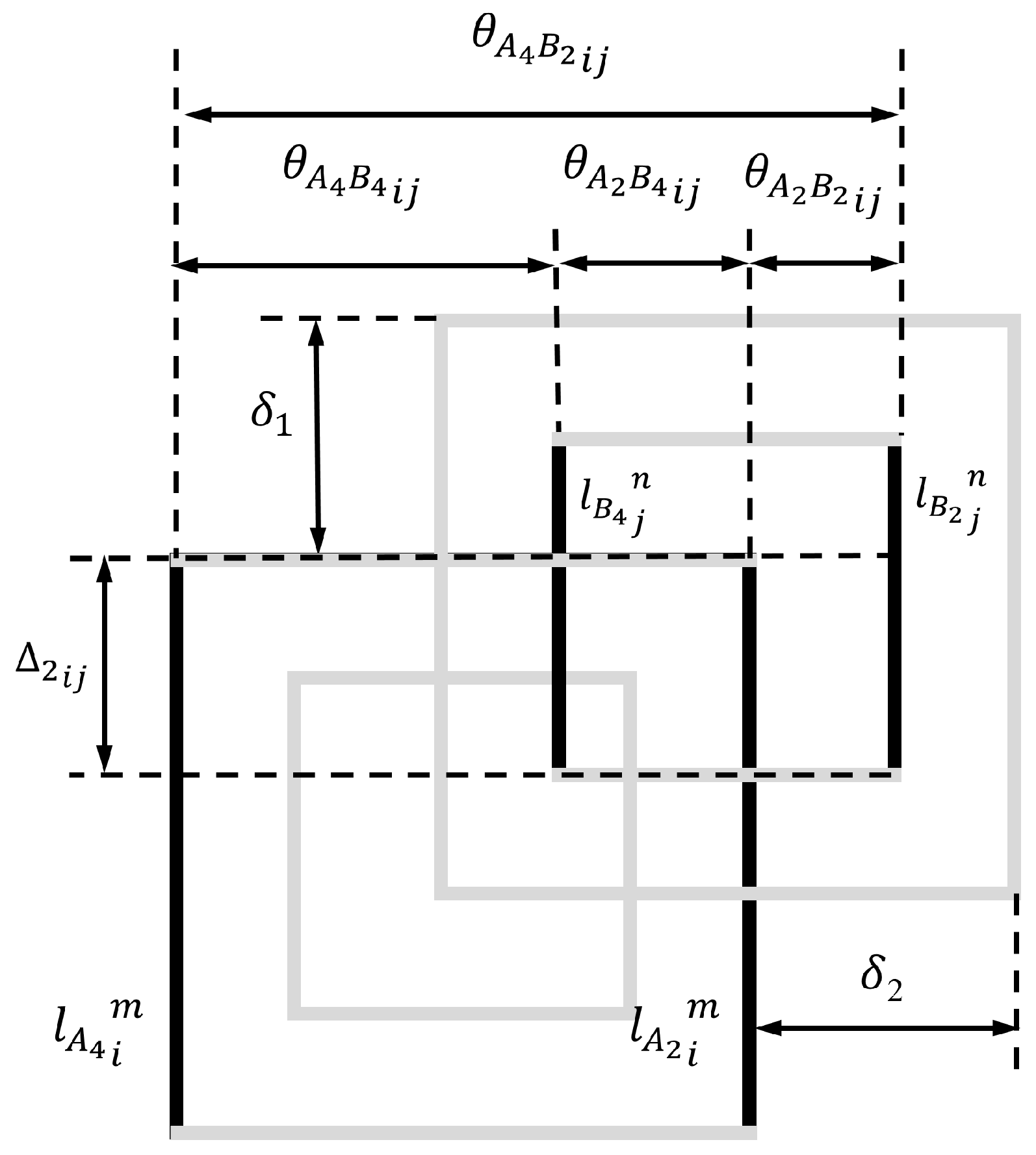
For ease of illustration and calculation, we consider the horizontally and vertically aligned filament pairs separately. The horizontally aligned situation concerns all the filaments at the side 1 and side 3 of both coils, as illustrated in Figure 8. The vertically aligned situation concerns all the filaments at the side 2 and side 4 of both coils, as illustrated in Figure 9. It is assumed that coil A is fixed and coil B moves with a vertical distance of δ 1 and a horizontal distance of δ 2 . The δ 1 and δ 2 are considered positive when the coil B moves up and right, referring to coil A. The full notation, created in the expressions (3)–(5), is followed. For example, l A 1 i m in Figure 8 refers to the length of the i- t h filament on the side 1 of m- t h layer of coil A. l B 1 j n refers to the length of the j- t h filament on the side 1 of n- t h layer of coil B. θ A 1 B 1 i j is the horizontal distance between the i- t h filament on the side 1 of coil A and the j- t h filament on the side 1 of coil B. θ A 1 B 1 m n is the vertical distance between the filament on the side 1 of m- t h layer of coil A and the filament on the side 1 of n- t h layer of coil B. And d A 1 B 1 i j m n is their diagonal distance.
For the horizontally aligned situations in Figure 8, when the square coil B moves up δ 1 and right δ 2 , the filaments on the side 1 and side 3 of coil B also move up δ 1 and right δ 2 , referring to the same filaments of coil A. Therefore, Δ 1 i j , the overlapping length of the filament pairs for both side 1 and side 3 are the same and are calculated as
Δ 1 i j = l i [ ( j i ) D + δ 2 ]
On the other hand, since the distances between the filament pairs of coil A and coil B are different for side 1 and 3, the horizontal distances between the filaments on the side 1 and 3 of the coil A and the filaments on the side 1 and 3 of the coil B are calculated for four different situations, given as
θ A 1 B 1 i j = ( i j ) D + δ 1 θ A 1 B 3 i j = a 1 ( i + j 2 ) D δ 1 θ A 3 B 3 i j = ( j i ) D + δ 1 θ A 3 B 1 i j = a 1 ( i + j 2 ) D + δ 1
where, for θ A x B y i j , when x = y , they refer to as the same-side (SS) situations; when x y , they refer to as the opposite-side (OS) situations.
Similarly for the vertically aligned situations in Figure 9, when the square coil B moves up δ 1 and right δ 2 , the filaments on the side 2 and side 4 of coil B also move up δ 1 and right δ 2 , referring to the same filaments of coil A. Therefore, Δ 2 i j , the overlapping length of the filament pairs for both side 2 and side 4 are calculated as
Δ 2 i j = l i [ ( j i ) D + δ 1 ]
The horizontal distances between the filaments on the side 2 and 4 of the coil A and the filaments on the side 2 and 4 of the coil B are also calculated for four different situations as
θ A 2 B 2 i j = ( i j ) D + δ 2 θ A 2 B 4 i j = a 1 ( i + j 2 ) D δ 2 θ A 4 B 4 i j = ( j i ) D + δ 2 θ A 4 B 2 i j = a 1 ( i + j 2 ) D + δ 2
The vertical distances between the m- t h layer of the coil A and the n- t h layer of the coil B are the same for all horizontal distance situations, given as
θ A x B y m n = ( 2 P m n ) × D + h
where h is the vertical distance between the top of the coil A and the bottom of the coil B, referred to in Figure 7.
Taking (20), (22) and (23), the distances between two filaments from the coil A and B are calculated as
d A x B y i j m n = ( θ A x B y i j ) 2 + ( θ A x B y m n ) 2
Now, we are able to calculate the mutual inductance between the coil A and B, using (18), separately, for the same-side situation, M A B S S , given as
M A B S S 1 = m , n = 1 P i , j = 1 N M o ( l A 1 i m , l B 1 j n , d A 1 B 1 i j m n , Δ 1 i j ) M A B S S 2 = m , n = 1 P i , j = 1 N M o ( l A 2 i m , l B 2 j n , d A 2 B 2 i j m n , Δ 2 i j ) M A B S S 3 = m , n = 1 P i , j = 1 N M o ( l A 3 i m , l B 3 j n , d A 3 B 3 i j m n , Δ 1 i j ) M A B S S 4 = m , n = 1 P i , j = 1 N M o ( l A 4 i m , l B 4 j n , d A 4 B 4 i j m n , Δ 2 i j ) M A B S S = M A B S S 1 + M A B S S 2 + M A B S S 3 + M A B S S 4
and opposite-side situation, M A B O S , given as
M A B O S 1 = m , n = 1 P i , j = 1 N M o ( l A 3 i m , l B 1 j n , d A 3 B 1 i j m n , Δ 1 i j ) M A B O S 2 = m , n = 1 P i , j = 1 N M o ( l A 4 i m , l B 2 j n , d A 4 B 2 i j m n , Δ 2 i j ) M A B O S 3 = m , n = 1 P i , j = 1 N M o ( l A 1 i m , l B 3 j n , d A 1 B 3 i j m n , Δ 1 i j ) M A B O S 4 = m , n = 1 P i , j = 1 N M o ( l A 2 i m , l B 4 j n , d A 2 B 4 i j m n , Δ 2 i j ) M A B O S = M A B O S 1 + M A B O S 2 + M A B O S 3 + M A B O S 4
Finally, the total mutual inductance between two multi-turn, multi-layer square coils, M A B , with misalignment, δ 1 and δ 2 , is calculated as
M A B = M A B S S M A B O S
The derived Equations (8)–(27) can be applied to N-turn P-layer square coils by adjusting the number of turns and layers.
Once both the self- and mutual-inductance of two coils are obtained, the coupling coefficient, k, can be calculated straightforwardly as
k = M A B L A × L B
where L A and L B are the self inductance of the coil A and B, respectively.

4. 3D Coil Modelling and Simulation

4.1. Model Development

Three-dimensional coil modelling and simulation can help not only to calculate the self- and mutual-inductance and the coupling coefficients of coils but also to visualize the magnetic flux distribution of the coils. When building the 3D coil model in COMSOL, the 3D geometric model of the four-turn, four-layer square coil directly imported from SOLIDWORKS, shown in Figure 1, is centrally surrounded by an extra air-filled block of an infinite element domain with a boundary layer of 70   m m as the region of free space, whose dimension is 600   m m × 600   m m × 600   m m . The exterior dimensions of the coils are 253   m m × 253   m m × 18   m m . In the 3D coil model and physical prototype, the litz cable is used to reduce the skin effect and ensure uniform current distribution over the cross-section of the round wire. The diameter of the litz cable ( 900 × 0.1   m m ) is 4   m m with insulation and 3 m m without insulation. Thus, 3 m m is used as the cross-section diameter of the wires in the 3D coil model, not including the insulation layer, which was incorporated into the horizontal and vertical gaps between two round wires.
When defining materials, air is specified for both block and coil domains but copper is only for the coil domain. By defining the materials, it is to define the relative permeability, electrical conductivity and relative permittivity for the magnetization model, conduction model and constitutive relation model under the coil feature. The stationary study under the “Magnetic field” interface was chosen to calculate the magnetic field of the coils. Ampere’s law was applied to all the domains to solve the magnetic field induced by a source such as current. The self-inductance is the constant of proportionality between the magnetic flux and the current. Magnetic insulation is set for the ground plate, which is the fact that the two terminals of the coils are connected. A perfect magnetic conductor was applied to all the faces of the block, except the ground plate, to ensure that the excitation is only for the coil, not other perfect conductors, so that no current flows on other faces. In this way, the coil is modelled within an ideal environment with good boundary conditions. There are no other current sources interfering in the calculations of the self-inductance of the coil and the mutual inductance between two coils. A similar finite element method (FEM) is used for a one-layer rectangular coil [34]. Others proposed to use a 3D electromagnetic solver in HFSS along with the formula of mutual inductance derived from Neumann’s equation to predict the mutual inductance [35] since other methods involve more complex numerical operations, i.e., lookup table and numerical integration of elliptical function, etc.

4.2. Self Inductance

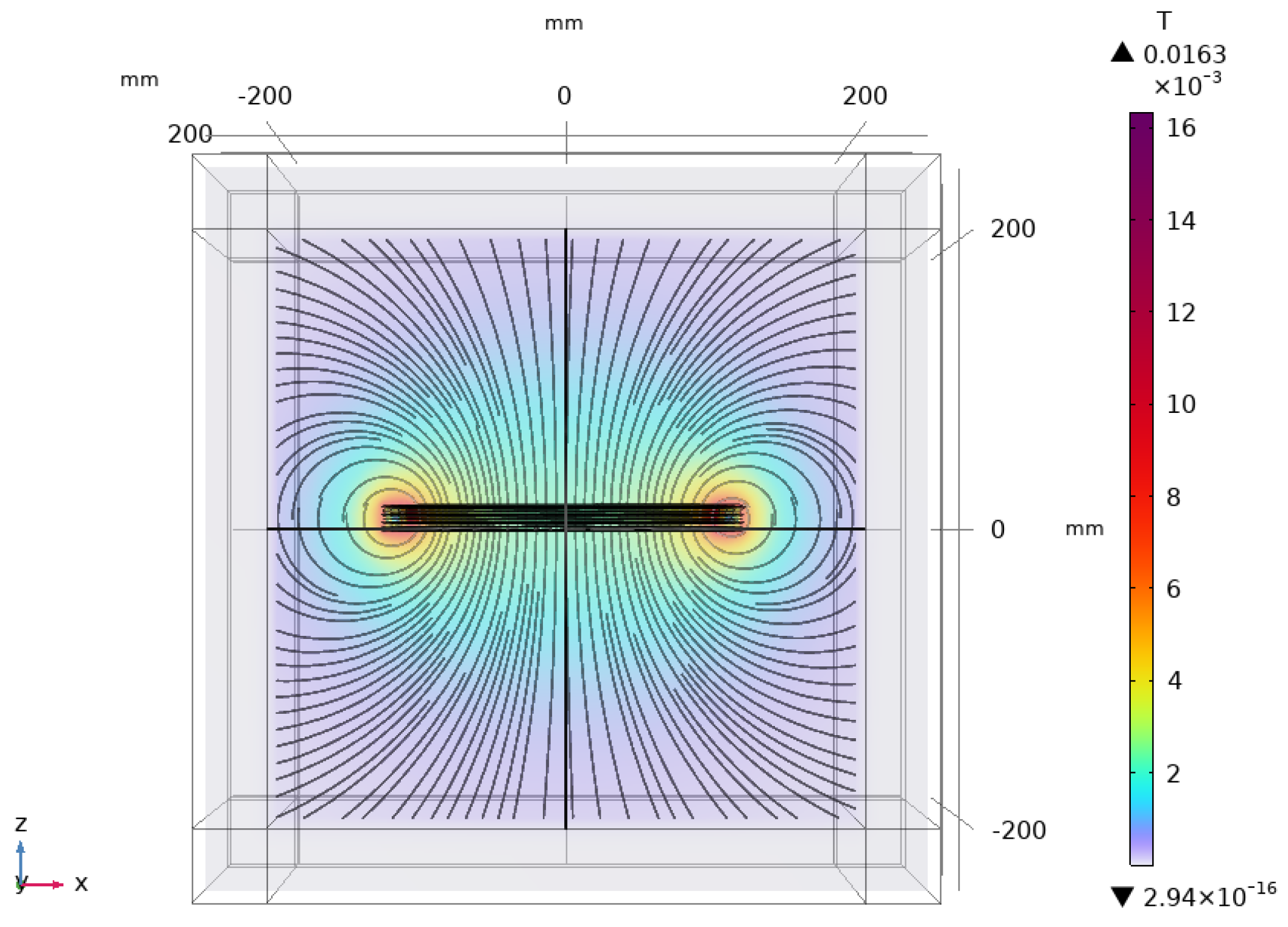
When simulating the magnetic fields and calculating the self-inductance of the coil, a 1 V voltage across the two terminals of the coil is defined as the excitation to form a complete current loop. Since the theoretical calculation is carried out in low frequency to ensure uniform current distribution, a stationary study is thus conducted to calculate its self-inductance and magnetic flux density. After simulation, the self-inductance of the coil is calculated to be 111.48   μ H . The magnetic flux density distribution of the coil and the magnetic flux density distribution path using a streamline plot are presented in Figure 10, showing a quite uniform magnetic flux density distribution of the coil. Obviously, the magnetic flux density reaches the maximum when close to the wires.

4.3. Mutual Inductance

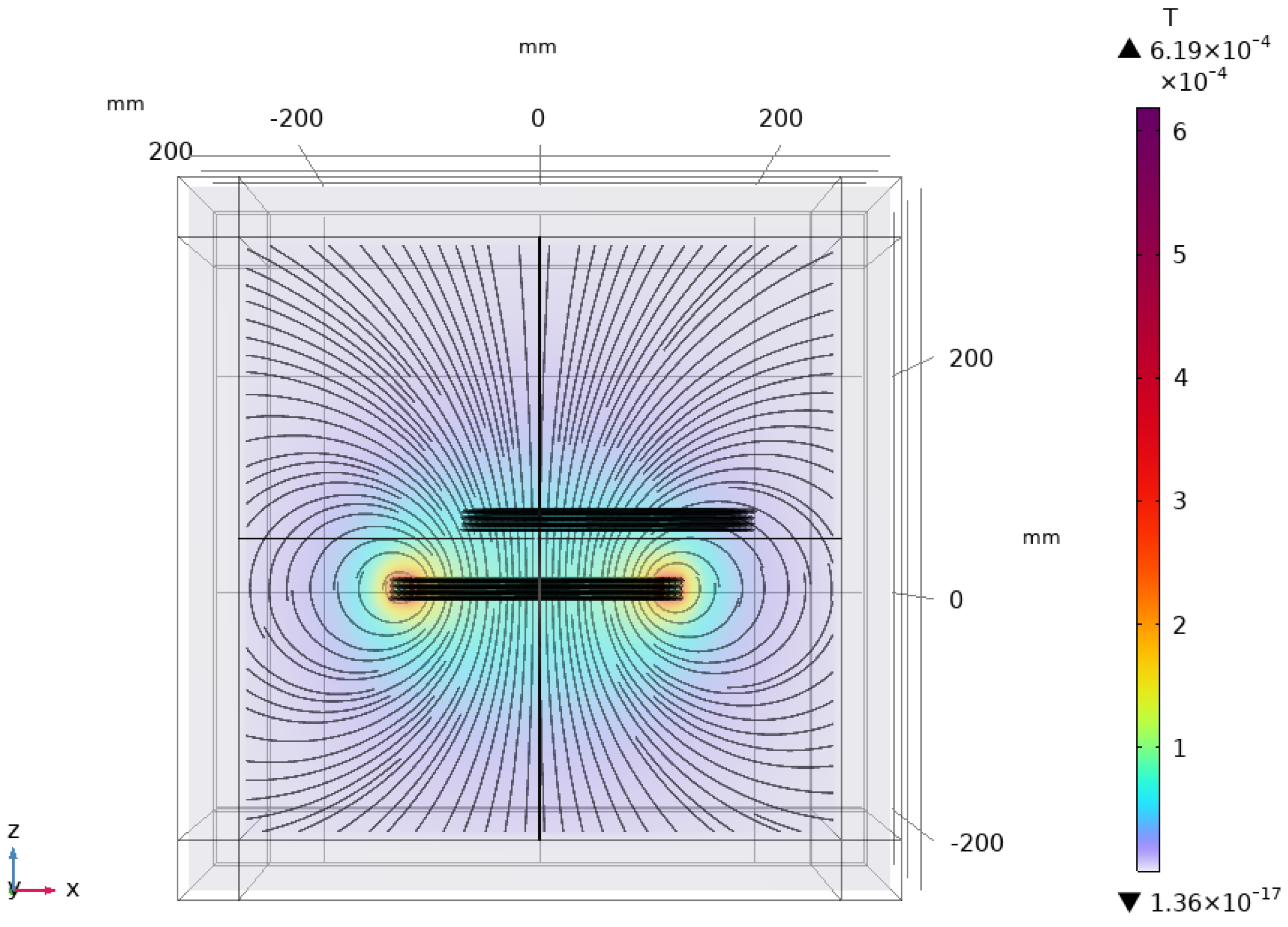
To calculate the mutual inductance of two four-turn, four-layer coils identical to Figure 1, the same simulation environment as in Section 4.1 is defined. Stationary studies were conducted to calculate the mutual inductance between the coils. To understand how vertical distance and misalignment affect their mutual inductance, 36 scenarios were generated by varying their vertical distances from 6 m m to 160 m m and one side of lateral misalignment, δ 1 , from 0 m m to 90 m m , respectively. Figure 11 presents one instance of the magnetic density of the lower coil and the mutual flux between the coils, with the vertical distance, h = 40   m m and the lateral misalignment, δ 1 = 30   m m , respectively. Eventually, the coupling coefficient is calculated for each given position.

5. Practical Measurement

As part of the study, two prototypes of the four-turn, four-layer square coil in Figure 1 were constructed, as shown in Figure 12, and used for measuring the self- and mutual-inductance and calculating the coupling coefficients under different misalignment situations.

5.1. Self Inductance

In order to measure its self-inductance, the coil is fixed on a platform, which is 66 c m away from the ground. An R&S® (Munich, Germany) HM8118 LCR meter is used to measure the self-inductance, with a chosen frequency of 1 kHz since the formulae used in the theoretical model section in Section 3 are in low frequency. The measured self-inductance of the four-turn, four-layer square coil results in 117.34   μ H with an averaged error of 0.43 % , operation frequency 1 k Hz , and impedance value 0.743   Ω [36].

5.2. Mutual Inductance

There are three methods to measure the mutual inductance between two coils and calculate the coupling coefficients. The first method is to measure the Root Mean Square (RMS) value of the primary coil voltage and the secondary coil voltage when applying an AC voltage across the two terminals of the primary coil. The coupling coefficient is calculated using (30). The second method is to measure the leakage inductance of the primary coil with the short-circuited secondary coil and the coupling coefficient is calculated using (32). The third method is to calculate the mutual inductance by measuring two equivalent self-inductance when connecting two coils in series with the same and opposite current flow directions, respectively [37]. The measurement results using the three methods are similar. In this paper, the first two methods were chosen as they are more efficient when conducting large amounts of measurements manually. Both methods are based on two coupled coil circuit models shown in Figure 13.
The corresponding theoretical model for both measurement methods is given as
V 1 = j ω L p I 1 + j ω M I 2 V 2 = j ω M I 1 + j ω L s I 2

5.2.1. Voltage Measurement Method

When the secondary coil is an open circuit, I 2 = 0 . In this case, a sinusoidal AC voltage with 10 V amplitude and 1 k Hz frequency is applied using Keysight Arbitrary Waveform Generator, and two FLUKE true RMS multi-meters are used to measure V 1 and V 2 , respectively. The coupling coefficient, k, is calculated as
k = V 2 V 1 = M L p

5.2.2. Leakage Inductance Measurement Method

When the secondary coil is short-circuited, V 2 = 0 , from (29), we derive
V 1 j ω I 1 = L p M 2 L s
The leakage inductance of the primary coil, L p M 2 L s , is obtained by measuring the inductance of the primary coil. Rearranging the equation, we obtain the coupling coefficient
k = 1 L s c s e c L p
where L p is the inductance of the primary coil when the secondary coil is an open circuit; L s c s e c is the leakage inductance of the primary coil when the secondary coil is short-circuited.
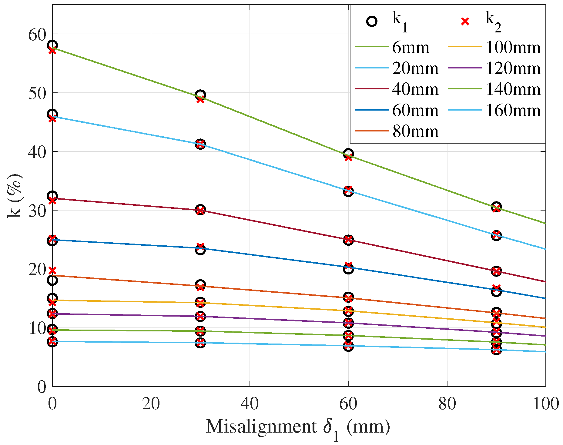
Figure 14 presents the coupling coefficients k 1 and k 2 , obtained using the voltage measurement method and the leakage inductance measurement method, respectively. During the measurements, the vertical distance varied from 6 m m to 160 m m , and the misalignment was realized only on one side by changing δ 1 from 0 m m to 90 m m , and there was no misalignment on the other side of the coil, i.e., δ 2 = 0 . Out of this range, the measured mutual inductance was close to zero and, therefore, not presented in this study. In reality, the DWPT system will rarely operate under such low coupling coefficient conditions, i.e., 0.01 , as the system becomes inefficient even with compensation and difficult to tune when the operating environment changes [38]. As shown in Figure 14, the resultant coupling coefficients, k 1 and k 2 , agree well with each other under different misalignment situations.

6. Cross-Validation

6.1. Self Inductance

In this section, the self-inductance of the four-turn, four-layer square coil is cross-validated using the three methods discussed in earlier sections, i.e., theoretical calculation, 3D coil modelling and simulation in COMSOL, and practical measurement of a laboratory prototype. The results and their Normalised Root Mean Square Errors (NRMSEs) are shown in Table 2.
In general, the results obtained by these three methods are close to each other, although an ideal environment is assumed for both the simulation and theoretical calculations. The equivalent true square coil model has a 1.24 % bigger surface area than the real square coil, which explains why the values are slightly higher than the results of the simulation. Moreover, the measurements are made in the university lab, not in an ideal environment, e.g., an anechoic chamber. Thus, the coils are not isolated from other surrounding energy sources, and consequently, the measurement values of self-inductance are higher than the results of the simulation and theoretical calculation. The theoretical calculation, simulation, and measurement results lie well within the range and close to the mean value, with an average NRMSE of 1.04 % .

6.2. Mutual-Inductance

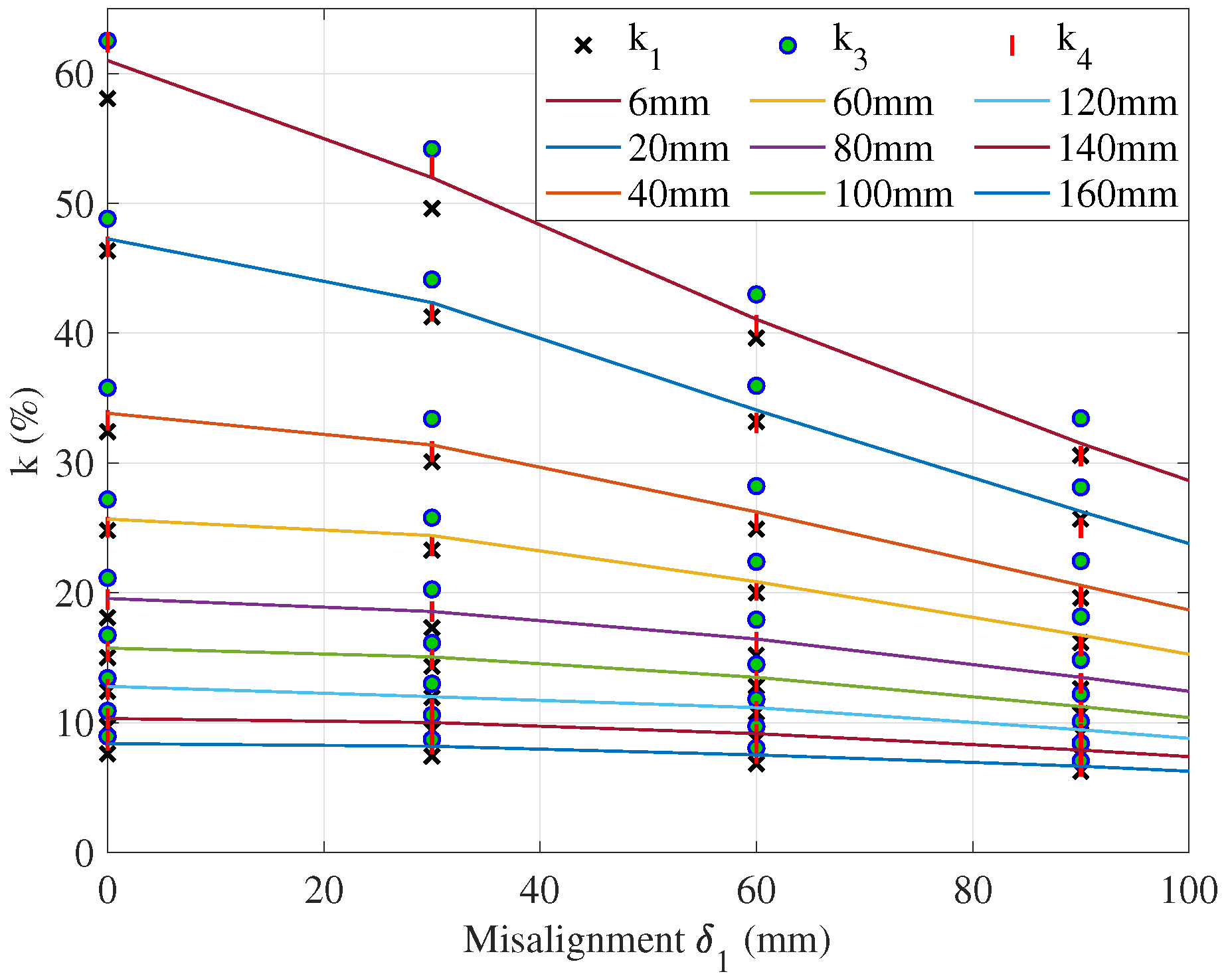
The coupling coefficients between the two four-turn, four-layer square coils are presented in Table 3. k 1 , k 2 , k 3 , and k 4 represent the coupling coefficients obtained using the voltage measurement, leakage inductance measurement, theoretical calculation, and simulation, respectively. The results of the coupling coefficient, k, obtained by varying the vertical distance and lateral misalignment, δ 1 , follow the same trend for the four data sets. When the vertical distance increases, the coupling coefficients decrease. Similarly, when the lateral misalignment, δ 1 , increases, the coupling coefficients decrease. The differences in the NRMSE among the four methods are mostly less than 10 % , with an average of 4.29 % . Generally, k 3 is slightly higher than k 1 , k 2 , and k 4 since the resultant self- and mutual-inductance are proportional to the area and the equivalent model has 1.24 % bigger area than the real geometry. Further validation results are shown in Figure 15. k 1 , k 3 and k 4 present the results obtained using the voltage measurement method, theoretical calculation, and 3D coil simulation, respectively. For better clarity, the results obtained using the leakage inductance measurement method, k 2 , were not included here, since the values k 1 and k 2 are both measurement results and close to each other. Each line represents one vertical distance variation, h, which increases from 6 m m to 160 m m from top to bottom. The x axis represents the misalignment, δ 1 , which increases from 0 m m to 100 m m . For each misalignment, three data points, representing the results obtained using the three methods, lie close to the mean value line.

7. Theoretical–Experimental Verification

Based on the circuit diagram of a previously studied Series-Series WPT (SS-WPT) system [26], an experimental set-up is established to indirectly verify the cross-validated coupling coefficients, as shown in Figure 16. The two coils are the ones validated by the three methods earlier, in Section 3, Section 4 and Section 5. The primary coil is connected to the inverter and the secondary coil is connected to the secondary board, which is connected with a resistive load. The inverter consists of four MOSFETs that can operate up to a frequency of 200 kHz. Additionally, the SS-WPT system includes two capacitors and a resistor. The values of these components, as well as their DC and AC losses, are measured across different frequencies to ensure the consistency of the theoretical model of the SS-WPT system and the actual experimental set-up. A DC power supply is used as the input power source.
Since the coupling coefficients are difficult to measure directly during the experiments, alternatively, they are verified by comparing some other characteristic parameters of the system, such as zero phase angle (ZPA) frequency, which can be measured in the experiments and calculated using the theoretical model with the cross-validated coupling coefficients. ZPA is the frequency that ensures the input current and voltage are in phase and the system is operated at high power transfer and high efficiency [39]. Therefore, the switching losses of the MOSFETs in the experimental set-up are not taken into account in the theoretical model of the SS-WPT system. During the process, the cross-validated coupling coefficients are loaded to the dimensionless theoretical model of an SS-WPT system [26] to calculate the ZPA frequencies, ω z , which are then compared with the ZPA frequencies found from the experimental set-up. In this case, the ZPA frequencies are normalized by the resonance frequency of the primary side of the DWPT system. Practically, these frequencies can be straightforwardly observed by measuring the input voltage and current of the experimental set-up. Hence, the ZPA frequencies can be found by manually altering the frequencies applied to the experimental set-up. The resultant ZPA frequencies for each given coupling coefficient of a resonance coupling WPT system are limited and precise. That is to say, for each coupling coefficient, k, there is not a range of frequencies but only one or two exact corresponding ZPA frequencies [26]. In order to find the exact ZPAs, all the component values of the theoretical model, especially the coupling coefficients, need to be close to the corresponding parameters of the experimental set-up. Therefore, for validation purposes, it is sufficient to select one instance from the cross-validation scenarios in Table 3.
Specifically, the coupling coefficients, k 1 , of the voltage measurement method under four misalignment situations with a vertical distance of 6 mm are selected for further verification. The calculated ZPA frequencies of the theoretical model are shown and highlighted in red in Figure 17, and the corresponding ZPA frequencies of the experimental set-up are highlighted in blue. Considering the acceptable ranges of the operation errors, i.e., the resolution of the oscillate scope, the measurement of two coils’ positions, etc., the results from these two methods match very well. It can be also seen clearly from Figure 17 that, for each given coupling coefficient, the two ZPA efficiencies are separated into lower or higher than 1, as expected. The more detailed results can be found in Table 4. The average NRMSE of the entire ZPA frequencies is 1.32 % . Specifically, the average NRMSEs of the ZPA frequencies, for both situations ( ω z < 1 and ω z > 1 ), are 0.635 % and 2.005 % , respectively.

8. Conclusions

Dynamic wireless power transfer is a promising solution for charging EVs. However, the coupling coefficient depends on the relative position between the transmission coil buried under the road and the receiver coil attached to the bottom of the EV, leading to low power transfer. This problem can be addressed by optimizing control frequencies. In order to find the optimal frequencies from the theoretical modelling of the DWPT, the first step is to calculate the self- and mutual-inductance and coupling coefficient of the coils. Therefore, a physical four-turn, four-layer square coil is built to verify the proposed theoretical model. By cross-validation, the well-matched results of the theoretical calculation, 3D coil simulation, and practical measurement methods not only confirm the results of the self and mutual inductance and coupling coefficients of the coils but also give us the confidence to extend these methods to deal with more complex systems and situations, such as designing and operating on-road multi-coil DWPT systems under dynamic and misaligned conditions. Even though the coupling coefficients are difficult to measure during operation, it is feasible to indirectly verify them by comparing some other characteristic parameters which are measurable in the experimental set-up, such as ZPA frequencies, and can be calculated using a theoretical model with the cross-validated coupling coefficients. The results of this paper provide a solid foundation to develop an optimal control strategy for EVs’ dynamic wireless charging systems.
Furthermore, the developed theoretical model can also be used for the design and optimization of multi-turn, multi-layer coils, with respect to a range of coil parameters. Alternatively, when the situations become more complex, the theoretical calculation and practical measurement can become difficult and time-consuming to evaluate and operate. In such cases, the 3D coil modelling and simulation method may be more favoured for calculating the self- and mutual-inductance and the coupling coefficients of complex multi-coil DWPT systems under different misalignment and vertical distance situations, providing better information for analyzing and controlling the DWPT systems. However, practical measurement methods can provide fast ways to measure the self- and mutual-inductance of the coils and coupling coefficients when the coils are available.

Author Contributions

All authors contributed to this work. Conceptualization, M.L. and K.E.K.D.; Methodology, M.L.; Software, M.L.; Validation, M.L.; Formal analysis, M.L.; Investigation, M.L.; Resources, M.L., K.E.K.D. and C.P.; Data curation, M.L.; Writing—original draft preparation, M.L.; Writing—review and editing, M.L., K.E.K.D. and C.P.; Visualization, M.L.; Supervision, K.E.K.D. and C.P.; Project administration, K.E.K.D. and C.P.; Funding acquisition, K.E.K.D. All authors have read and agreed to the published version of the manuscript.

Funding

This work was supported by the International Research Center “Innovation Transportation and Production Systems” of the I-SITE CAP 20-25.

Data Availability Statement

No new data were created or analyzed in this study. Data sharing is not applicable to this article.

Acknowledgments

The authors would like to thank Marc Nivoix from Institut Pascal for constructing the frame of the coils used in this paper.

Conflicts of Interest

The authors declare no conflict of interest. The funders had no role in the design of the study; in the collection, analyses, or interpretation of data; in the writing of the manuscript; or in the decision to publish the results.

Abbreviations

The following abbreviations are used in this manuscript:
DWPTDynamic Wireless Power Transfer
EVElectric Vehicle
FEMFinite Element Method
IoTInternet of Things
WPTWireless Power Transfer
ZPAZero Phase Angle

References

  1. Tesla, N. Apparatus for Transmitting Electrical Energy. US Patent 1119732, 1 December 1914. [Google Scholar]
  2. Si, P.; Hu, A.P.; Malpas, S.; Budgett, D. A Frequency Control Method for Regulating Wireless Power to Implantable Devices. IEEE Trans. Biomed. Circuits Syst. 2008, 2, 918284. [Google Scholar] [CrossRef] [PubMed]
  3. Bakula, M.; Pelgrims, P.; Puers, R. A Wireless Powering and Communication System for Implantable Devices Based on a Royer Oscillator with Radio and Near-field Communication Links. Procedia Eng. 2015, 120, 306–309. [Google Scholar] [CrossRef]
  4. Han, S.; Wentzloff, D.D. Wireless power transfer using resonant inductive coupling for 3D integrated ICs. In Proceedings of the 2010 IEEE International 3D Systems Integration Conference (3DIC), Munich, Germany, 16–18 November 2010; pp. 1–5. [Google Scholar] [CrossRef]
  5. Riehl, P.S.; Satyamoorthy, A.; Akram, H.; Yen, Y.C.; Yang, J.C.; Juan, B.; Lee, C.M.; Lin, F.C.; Muratov, V.; Plumb, W.; et al. Wireless Power Systems for Mobile Devices Supporting Inductive and Resonant Operating Modes. IEEE Trans. Microw. Theory Tech. 2015, 63, 780–790. [Google Scholar] [CrossRef]
  6. Kuo, R.C.; Riehl, P.; Satyamoorthy, A.; Plumb, W.; Tustin, P.; Lin, J. A 3D resonant wireless charger for a wearable device and a mobile phone. In Proceedings of the 2015 IEEE Wireless Power Transfer Conference (WPTC), Boulder, CO, USA, 13–15 May 2015; pp. 1–3. [Google Scholar] [CrossRef]
  7. Shinohara, N. Trends in Wireless Power Transfer: WPT Technology for Energy Harvesting, Mllimeter-Wave/THz Rectennas, MIMO-WPT, and Advances in Near-Field WPT Applications. IEEE Microw. Mag. 2021, 22, 46–59. [Google Scholar] [CrossRef]
  8. Azad, A.; Teeneti, C.R.; Zane, R.; Pantic, Z. DAB-based WPT Charger with Integrated Battery Management System for Fast Charging of Mobility Devices. In Proceedings of the 2019 IEEE Transportation Electrification Conference and Expo (ITEC), Detroit, MI, USA, 19–21 June 2019; pp. 1–6. [Google Scholar] [CrossRef]
  9. Shoki, H. Issues and Initiatives for Practical Deployment of Wireless Power Transfer Technologies in Japan. Proc. IEEE 2013, 101, 1312–1320. [Google Scholar] [CrossRef]
  10. Hamam, R.E.; Karalis, A.; Joannopoulos, J.; Soljačić, M. Efficient weakly-radiative wireless energy transfer: An EIT-like approach. Ann. Phys. 2009, 324, 1783–1795. [Google Scholar] [CrossRef]
  11. Karalis, A.; Joannopoulos, J.; Soljačić, M. Efficient wireless non-radiative mid-range energy transfer. Ann. Phys. 2008, 323, 34–48. [Google Scholar] [CrossRef]
  12. Kurs, A.; Karalis, A.; Moffatt, R.; Joannopoulos, J.D.; Fisher, P.; Soljačić, M. Wireless Power Transfer via Strongly Coupled Magnetic Resonances. Science 2007, 317, 83–86. [Google Scholar] [CrossRef]
  13. Imura, T.; Okabe, H.; Hori, Y. Basic experimental study on helical antennas of wireless power transfer for Electric Vehicles by using magnetic resonant couplings. In Proceedings of the 2009 IEEE Vehicle Power and Propulsion Conference, Dearborn, MI, USA, 7–10 September 2009; pp. 936–940. [Google Scholar] [CrossRef]
  14. Mou, X.; Gladwin, D.T.; Zhao, R.; Sun, H. Survey on magnetic resonant coupling wireless power transfer technology for electric vehicle charging. IET Power Electron. 2019, 12, 3005–3020. [Google Scholar] [CrossRef]
  15. Li, S.; Liu, Z.; Zhao, H.; Zhu, L.; Shuai, C.; Chen, Z. Wireless Power Transfer by Electric Field Resonance and Its Application in Dynamic Charging. IEEE Trans. Ind. Electron. 2016, 63, 6602–6612. [Google Scholar] [CrossRef]
  16. Cai, C.; Wang, J.; Fang, Z.; Zhang, P.; Hu, M.; Zhang, J.; Li, L.; Lin, Z. Design and Optimization of Load-Independent Magnetic Resonant Wireless Charging System for Electric Vehicles. IEEE Access 2018, 6, 17264–17274. [Google Scholar] [CrossRef]
  17. Aydin, E.; Aydemir, M.T.; Aksoz, A.; El Baghdadi, M.; Hegazy, O. Inductive Power Transfer for Electric Vehicle Charging Applications: A Comprehensive Review. Energies 2022, 15, 4962. [Google Scholar] [CrossRef]
  18. Feng, H.; Cai, T.; Duan, S.; Zhao, J.; Zhang, X.; Chen, C. An LCC-Compensated Resonant Converter Optimized for Robust Reaction to Large Coupling Variation in Dynamic Wireless Power Transfer. IEEE Trans. Ind. Electron. 2016, 63, 6591–6601. [Google Scholar] [CrossRef]
  19. Panchal, C.; Stegen, S.; Lu, J. Review of static and dynamic wireless electric vehicle charging system. Eng. Sci. Technol. Int. J. 2018, 21, 922–937. [Google Scholar] [CrossRef]
  20. Barsari, V.Z.; Thrimawithana, D.J.; Covic, G.A. An Inductive Coupler Array for In-Motion Wireless Charging of Electric Vehicles. IEEE Trans. Power Electron. 2021, 36, 9854–9863. [Google Scholar] [CrossRef]
  21. Song, B.; Cui, S.; Li, Y.; Zhu, C. A Fast and General Method to Calculate Mutual Inductance for EV Dynamic Wireless Charging System. IEEE Trans. Power Electron. 2021, 36, 2696–2709. [Google Scholar] [CrossRef]
  22. Budhia, M.; Covic, G.A.; Boys, J.T. Design and Optimization of Circular Magnetic Structures for Lumped Inductive Power Transfer Systems. IEEE Trans. Power Electron. 2011, 26, 3096–3108. [Google Scholar] [CrossRef]
  23. Choi, Y.; Kwak, B.; Kim, M. 4kW magnetic resonance wireless power transfer system. In Proceedings of the 2016 IEEE International Conference on Power System Technology (POWERCON), Wollongong, Australia, 28–30 September 2016; pp. 1–3. [Google Scholar] [CrossRef]
  24. Mahesh, A.; Chokkalingam, B.; Mihet-Popa, L. Inductive Wireless Power Transfer Charging for Electric Vehicles—A Review. IEEE Access 2021, 9, 137667–137713. [Google Scholar] [CrossRef]
  25. Budhia, M.; Boys, J.T.; Covic, G.A.; Huang, C.Y. Development of a Single-Sided Flux Magnetic Coupler for Electric Vehicle IPT Charging Systems. IEEE Trans. Ind. Electron. 2013, 60, 318–328. [Google Scholar] [CrossRef]
  26. Liang, M.; Khamlichi Drissi, K.E.; Pasquier, C. Optimal frequency for Dynamic Wireless Power Transfer. In Proceedings of the 2022 24th European Conference on Power Electronics and Applications (EPE’22 ECCE Europe), Hanover, Germany, 5–9 September 2022; pp. 1–10. [Google Scholar]
  27. Patil, D.; McDonough, M.K.; Miller, J.M.; Fahimi, B.; Balsara, P.T. Wireless Power Transfer for Vehicular Applications: Overview and Challenges. IEEE Trans. Transp. Electrif. 2018, 4, 3–37. [Google Scholar] [CrossRef]
  28. Grover, F.W. Inductance Calculations; Dover Publications: Mineola, NY, USA, 2004. [Google Scholar]
  29. Maxwell, J.C. A Treatise on Electricity and Magnetism. In Cambridge Library Collection—Physical Sciences; Cambridge University Press: Cambridge, UK, 2010; Volume 1. [Google Scholar] [CrossRef]
  30. Rosa, E.B.; Frederick, W.G. Formulas and Tables for the Calculation of Mutual and Self-Inductance, Number 169, 3rd ed.; US Department of Commerce and Labor, Bureau of Standards: Washington, DC, USA, 1948. [Google Scholar]
  31. NIST. Circular of the Bureau of Standards C74: Radio Instruments and Measurements. NBS Circulars; National Institute of Standards and Technology (NIST), Commerce Department: Washington, DC, USA, 1937; p. 242.
  32. Rosa, E.B. The self and mutual inductance of linear conductors. Bull. Bur. Stand. 1908, 4, 301–344. [Google Scholar] [CrossRef]
  33. López-Alcolea, F.J.; Real, J.V.d.; Roncero-Sánchez, P.; Torres, A.P. Modeling of a Magnetic Coupler Based on Single- and Double-Layered Rectangular Planar Coils With In-Plane Misalignment for Wireless Power Transfer. IEEE Trans. Power Electron. 2020, 35, 5102–5121. [Google Scholar] [CrossRef]
  34. Kushwaha, B.K.; Rituraj, G.; Kumar, P. 3-D Analytical Model for Computation of Mutual Inductance for Different Misalignments With Shielding in Wireless Power Transfer System. IEEE Trans. Transp. Electrif. 2017, 3, 332–342. [Google Scholar] [CrossRef]
  35. Raju, S.; Wu, R.; Chan, M.; Yue, C.P. Modeling of Mutual Coupling Between Planar Inductors in Wireless Power Applications. IEEE Trans. Power Electron. 2014, 29, 481–490. [Google Scholar] [CrossRef]
  36. Rohde & Schwarz GmbH & Co. KG. R&S® HM8118 LCR Bridge User Manual; Rohde & Schwarz GmbH & Co. KG.: Muhich, Germany, 2016. [Google Scholar]
  37. Su, Y.P.; Liu, X.; Hui, S.Y.R. Mutual Inductance Calculation of Movable Planar Coils on Parallel Surfaces. IEEE Trans. Power Electron. 2009, 24, 1115–1123. [Google Scholar] [CrossRef]
  38. Covic, G.A.; Boys, J.T. Modern Trends in Inductive Power Transfer for Transportation Applications. IEEE J. Emerg. Sel. Top. Power Electron. 2013, 1, 28–41. [Google Scholar] [CrossRef]
  39. Jiang, J.; Dai, X.; Hu, A.P. A Dynamic Tuning Method for ZPA Frequency Operation of MEU-WPT System by DC Input Voltages Regulation. IEEE Trans. Power Electron. 2022, 37, 11369–11381. [Google Scholar] [CrossRef]
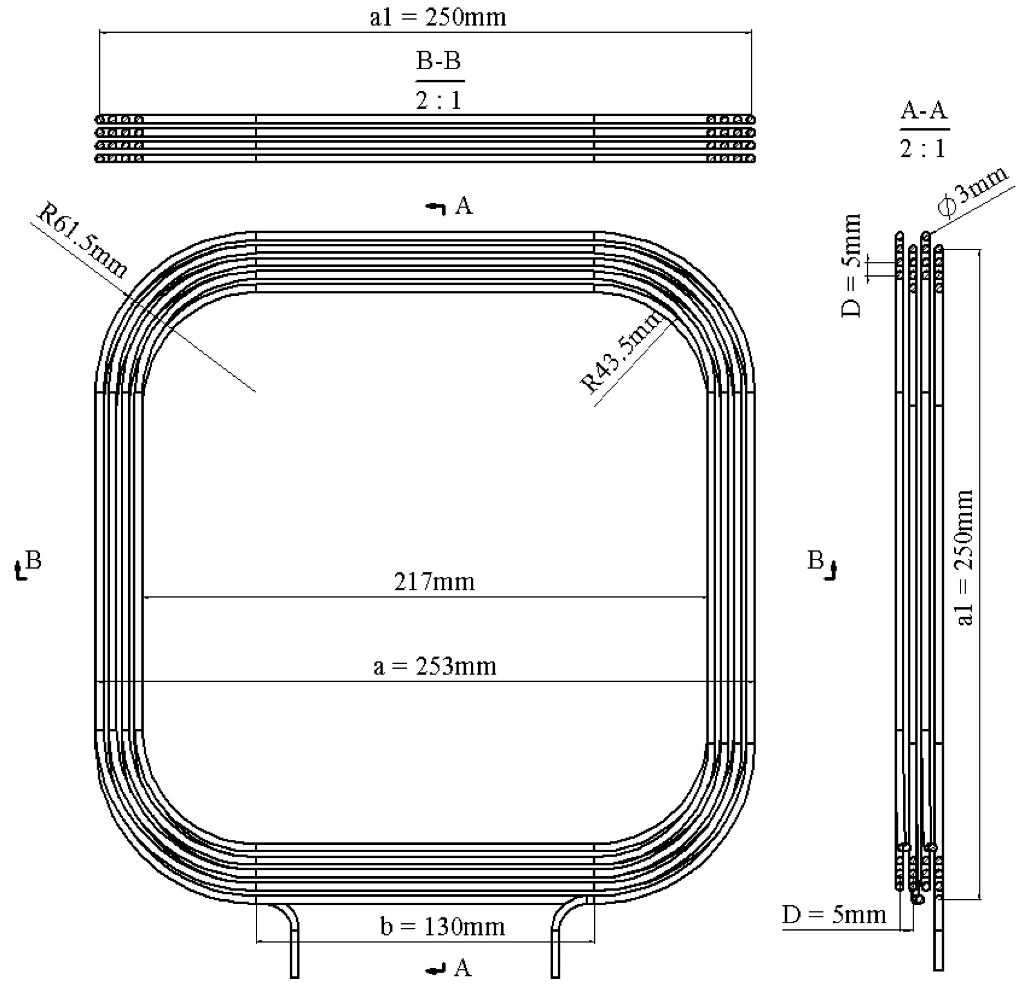
Figure 1. A multi-turn, multi-layer square coil with notations.
Energies 16 07033 g001
Figure 2. The equivalent filament model of a multi-turn, multi-layer square coil.
Energies 16 07033 g002
Figure 3. The horizontal cross-section drawing of the equivalent filament coil.
Energies 16 07033 g003
Figure 4. A special case of unequal parallel filament pairs.
Energies 16 07033 g004
Figure 5. Misalignment between two multi-turn, multi-layer square coils.
Energies 16 07033 g005
Figure 6. Overlap between two parallel filaments.
Energies 16 07033 g006
Figure 7. A cross-section illustration of misalignment between two multi-turn, multi-layer square coils.
Energies 16 07033 g007
Figure 8. An illustration of horizontally aligned filament pairs of two coils.
Energies 16 07033 g008
Figure 9. An illustration of vertically aligned filament pairs of two coils.
Energies 16 07033 g009
Figure 10. Magnetic flux density of one four-turn, four-layer square coil.
Energies 16 07033 g010
Figure 11. Magnetic flux density of two four-turn, four-layer square coils with vertical distance, h = 40   m m and lateral misalignment, δ 1 = 30   m m .
Energies 16 07033 g011
Figure 12. A physical prototype of the 4-turn, 4-layer square coil.
Energies 16 07033 g012
Figure 13. Two coils circuit diagram.
Energies 16 07033 g013
Figure 14. Measurement results ( k 1 , k 2 ) of two methods.
Energies 16 07033 g014
Figure 15. Measurement ( k 1 ), theoretical ( k 3 ), simulation ( k 4 ) coefficients’ results.
Energies 16 07033 g015
Figure 16. The experimental set-up.
Energies 16 07033 g016
Figure 17. Comparison of the ZPA frequencies between the theoretical model and experimental set-up.
Energies 16 07033 g017
Table 1. The key parameters and calculated self-inductance of a four-turn, four-layer square coil.
a 1 (cm)r (cm)D (cm) N P L coil ( μ H)
25.000.150.5044113.76
Table 2. The self inductance of a 4-turn, 4-layer square coil.
ResultsTheoretical ModelSimulationMeasurement
L coil ( μ H ) 113.76111.48117.34
NRMSE (%)0.512.573.02
Table 3. Coupling coefficients comparison among the measurement, theoretical calculation, and simulation.
VD *
(mm)
Misalignment  δ 1 = 0 mmMisalignment  δ 1 = 30 mm
M-1 * (%)M-2 * (%)T * (%)S * (%)M-1 (%)M-2 (%)T (%)S (%)
k 1 ε * k 2 ε k 3 ε k 4 ε k 1 ε k 2 ε k 3 ε k 4 ε
658.083.3057.234.7162.534.1162.413.9049.623.4648.914.8454.195.4552.892.85
2046.351.0945.612.6548.824.1946.650.4541.251.9741.251.9844.134.8741.690.92
4032.402.6531.654.9235.797.5233.300.0430.103.1229.9023.7633.407.5130.870.64
6024.812.8725.131.6127.196.4525.041.9723.273.5423.811.2925.796.9023.632.07
8018.087.8019.740.6821.157.8719.460.7617.315.1316.867.5820.2611.0518.551.66
10015.002.5214.336.8616.748.7915.480.5914.333.6814.184.6516.138.4414.860.12
12012.402.1412.332.7613.435.9512.541.0511.920.4411.940.3013.008.5511.047.81
1409.713.889.486.1210.907.8910.322.119.424.439.444.2610.597.409.991.29
1607.607.487.716.128.948.898.604.717.407.267.486.268.708.988.354.54
VD
(mm)
Misalignment  δ 1 =  60 mmMisalignment  δ 1 =  90 mm
M-1 (%)M-2 (%)T (%)S (%)M-1 (%)M-2 (%)T (%)S (%)
k 1 ε k 2 ε k 3 ε k 4 ε k 1 ε k 2 ε k 3 ε k 4 ε
639.622.3239.013.8242.996.0040.610.1430.582.0030.282.9533.447.1730.512.22
2033.172.2133.471.3435.955.9833.102.4225.671.8625.831.2428.137.5325.004.43
4024.903.9525.033.4728.228.8425.561.4119.623.5619.633.4822.4510.3719.663.32
6020.003.8020.600.9122.397.7020.172.9916.153.4416.710.1118.178.6115.885.06
8015.195.4214.946.9917.9311.6216.190.7812.604.7512.436.0214.8312.1413.041.38
10012.794.2412.962.9414.498.5013.181.3110.674.5411.021.4712.199.0210.853.14
12010.772.7910.861.9611.816.6010.871.859.132.949.301.1410.097.219.123.14
1408.654.198.693.789.717.509.080.487.503.987.602.748.417.687.740.96
1606.837.557.024.998.048.887.653.656.254.476.254.507.057.766.621.21
* Note: VD—vertical distance; M-1—voltage measurement method; M-2—leakage inductance measurement method; T—theoretical calculation; S—simulation; ε —NRMSE.
Table 4. ZPA frequencies.
δ 1 ( m m ) k 1 ( % ) ω z 1 < 1 ω z 2 < 1 NRMSE ( % ) ω z 1 > 1 ω z 2 > 1 NRMSE ( % )
058.080.79240.79440.851.50971.51673.28
3049.620.82410.81830.731.37301.38233.60
6039.620.85600.84980.711.21591.26050.68
9030.580.89010.88260.251.13481.17260.46
Note: ω z 1 —ZPA frequency of the experimental set-up; ω z 2 —ZPA frequency of the theoretical model.
Disclaimer/Publisher’s Note: The statements, opinions and data contained in all publications are solely those of the individual author(s) and contributor(s) and not of MDPI and/or the editor(s). MDPI and/or the editor(s) disclaim responsibility for any injury to people or property resulting from any ideas, methods, instructions or products referred to in the content.