Abstract
The paper presents a survey of the experimental and numerical studies of shell-and-tube systems in which phase change material (PCM) is used. Due to the multitude of design solutions for shell-and-tube systems, the emphasis is placed on double-tube (DT), triplex-tube (TT), and multi-tube (MT) units. Additionally, only single-pass systems are considered. Particular attention is paid to the method of heat transfer intensification. The analysis of the research results begins with the classification of each of the three mentioned systems. The systems are divided according to the angle of inclination, the method of heat transfer enhancement (HTE), the flow direction of heat transfer fluid (HTF), and the arrangement of tubes in the bundle. Moreover, the simplified schemes of the particular research cases are proposed. Then, the works on each of the mentioned systems, i.e., DT, TT, and MT, are discussed chronologically. Finally, in the corresponding tables, details of the discussed cases are presented, such as geometric dimensions, and the type of PCM or HTF used. A novelty in the present work is the precise classification of PCM TESUs as DT, TTH, and MTH. In the literature, there is a lot of discretion in this regard. Second, the methods of heat transfer intensification in the presented PCM TESUs are listed and discussed. Third, unified schemes of design solutions for the discussed PCM TESUs are proposed. The review shows that development directions for shell-and-tube TESUs include systems with high conductivity fins of different shapes, heights, and spacing, several PCMs, and modified shells.
1. Introduction
Full use of renewable energy sources (RES) will be possible if the problem of energy storage is effectively solved. Problems with the utilization of RES result from intermittent RES operation, maladjustment of the instantaneous energy supply to demand, maladjustment of the operating temperature, and maladjustment of the location of the RES system and the energy system. In the case of solar energy, thermal energy storage is a major problem. There are three methods of thermal energy storage: in the form of sensible heat, latent heat, and thermochemically [1,2]. In terms of the operating temperature of energy systems up to 100 °C, the most promising is the use of PCM [3].
The key shortcoming of phase change materials (PCMs) is their weak thermal conductivity resulting in low intensity of heat transfer leading to long charging and discharging times of thermal energy storage units (TESU). Thus, various techniques are used to improve heat transfer in PCMs systems. The simplest one is, of course, increasing the heat transfer surface. This is achieved, for example, by the use of extended surfaces, and finned surfaces, e.g., [4,5]. Another way is to use inserts immersed in PCM with a large surface area and high thermal conductivity, such as carbon brushes [6,7], metal foams [8,9], porous materials [10,11,12], metal rings [13,14], or metal matrices [15,16]. Another possibility is the use of honeycomb fillers [17,18]. A considered method is to use a bed of metal spheres that contain PCM [19]. A variation of this solution is the use of encapsulation techniques [20,21,22,23]. The use of nanoadditives, which, when mixed with the base PCM, forms a mixture (composite) characterized by a thermal conductivity much higher than the base PCM, is also considered, e.g., [24,25].
As for the construction of TESU, exceptionally attractive are—due to the mastered manufacturing technique—shell-and-tube systems. Many variants of possible solutions for shell-and-tube TESU are considered in the literature. For a given design, TESU capacity, charging and discharging time, PCM temperature distributions, the influence of HTF parameters, etc., are tested. Numerical studies have shown that during PCM solidification, heat conduction is the dominant mechanism all the time, while during the melting stage, in the initial period, heat conduction is the dominant heat transfer mechanism, and when the liquid phase appears, free convection is the dominating mechanism of heat transfer. Hence, the geometry of the system in which the melting process takes place is very important.
The paper presents the state of knowledge concerning three types of shell-and-tube systems used as potential TESUs, namely double-tube units, triplex-tube units, and multi-tube units. The review includes systems in which methods of heat transfer intensification were applied based on an extension of the heat exchange surface. Methods of direct increase of the thermal conductivity of PCM, such as nanoPCM, were not considered in this paper.
2. Materials and Methods
2.1. Double-Tube Units
Double-tube systems have been divided into three main groups, namely horizontal (DTH)—Figure 1, vertical (DTV)—Figure 2, and inclined (DTI)—Figure 3. This division results from the influence of free convection on the PCM melting and solidification processes. Regardless of the angle of inclination, the division of DT units results from the arrangement of PCM and HTF. Two solutions are considered. In the first, the PCM fills the shell side, and the HTF flows in the tube. In the second, the PCM is placed inside the tube, and the HTF flows in the annular gap. The proposed classification takes into account the methods of heat transfer intensification, both on the PCM and HTF sides. In the case of vertical DT, the direction of HTF flow—in line with or against gravity—is important. It is also important to indicate whether the DT unit was used only for the charging or discharging process, or for both processes. Thus, for example, Case DTH-ILF-VG-M concerns a horizontal arrangement, in which the melting process took place and longitudinal fins were applied on the outer surface of the HTF tube, and a vortex generator was placed inside the HTF tube.
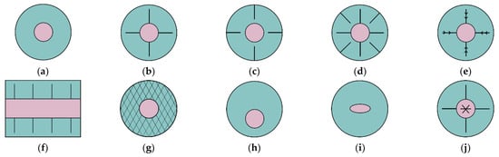
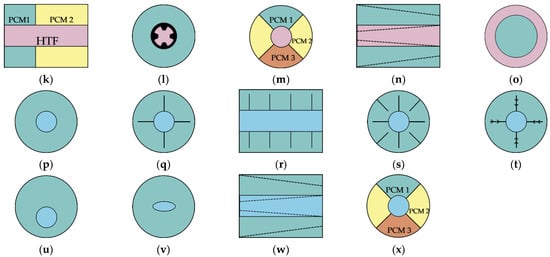
Figure 1.
Horizontal double-tube arrangements; (a) Case DTH-M; (b) Case DTH-ILF-M; (c) Case DTH-ELF-M; (d) Case DTH-ILF+ELF-M; (e) Case DTH-AF-M; (f) Case DTH-CF-M; (g) Case DTH-FO-M; (h) Case DTH-E-M; (i) Case DTH-EL-M; (j) Case DTH-ILF-VG-M; (k) Case DTH-MP-M; (l) Case DTH-IFT-MP-M; (m) Case DTH-ILF-MP-M; (n) Case DTH-FR-M; (o) Case DTH-SP-M; (p) Case DTH-S; (q) Case DTH-ILF-S; (r) Case DTH-CF-S; (s) Case DTH-ILF+ELF-S; (t) Case DTH-AF-S; (u) Case DTH-E-S; (v) Case DTH-EL-S; (w) Case DTH-FR-S; (x) Case DTH-ILF-MP-S.
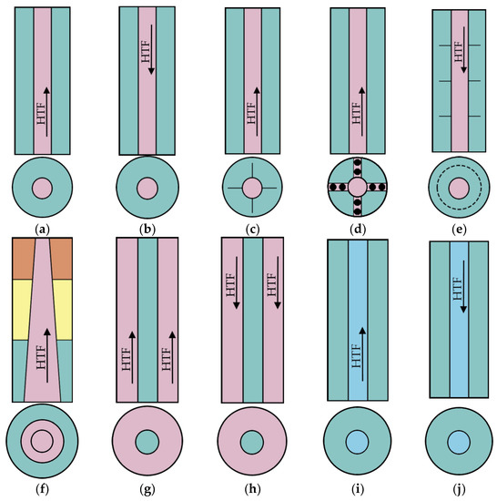
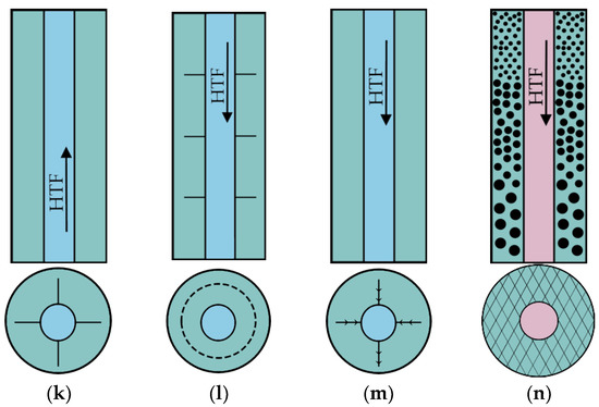
Figure 2.
Vertical double-tube arrangements; (a) Case DTV-B-M; (b) Case DTV-T-M; (c) Case DTV-B-ILF-M; (d) Case DTV-B-SC-M; (e) Case DTV-T-CF-M; (f) Case DTV-B-FR-MP-M; (g) Case DTV-B-SP-M; (h) Case DTV-T-SP-M; (i) Case DTV-B-S; (j) Case DTV-T-S; (k) Case DTV-B-ILF-S; (l) Case DTV-T-CF-S; (m) Case DTV-T-AF-S; (n) Case DTV-T-FO-M.
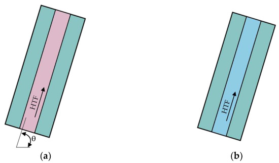
Figure 3.
Inclined double-tube arrangements; (a) Case DTI-B-M; (b) Case DTI-B-S.
More details of the considered cases are discussed in the following, and also presented in Table 1, Table 2 and Table 3.
Lacroix [26] showed numerically and confirmed experimentally that the efficacy of the DTH TESU—Figure 1a, depends on the shell-to-HTF tube diameter ratio, HTF flow rate, and inlet temperature. Ettouney et al. [27] established experimentally that the use of screen-ball inserts causes a 3-fold decrease in the melting time of PCM placed inside vertical DTV TESU—Figure 2d. Experimental and numerical investigations conducted by Trp [28] showed that only a small amount of HTF thermal energy is transferred to the PCM in the tested DTV TESU—Figure 2b,j. Adine and Qarnia [29] investigated the numerical influence of HTF mass flow rate and mass ratio of two PCMs on the melting performance of DTH TESU—Figure 1k. It was established that the maximum efficacy of the examined TESUs did not depend on the HTF inlet temperature. Chiu and Martin [30] showed numerically and confirmed experimentally that proper determination of the PCM thermophysical properties results in the accurate design of DTV TESU circular fins—Figure 2e,l. Avci and Yazici [31] established experimentally that an increase of the HTF inlet temperate improves the melting process, while a decrease in the HTF inlet temperate enhances the solidification process in DTH TESU—Figure 1a,p. Solomon and Velraj [32] investigated experimentally the influence of the internal longitudinal fin height on the solidification process in DTV TESU with a bottom HTF inlet—Figure 2k. It was found that the maximum intensification of heat transfer was achieved for the fin height of about 60% of the annular gap. Longeon et al. [33] showed numerically and confirmed experimentally that for DTV TESU—Figure 2a,b,i,j—top HTF inlet is preferable for the melting process and a bottom HTF inlet is superior for the solidification process. According to Longeon et al. [33], this is due to the fact that the top inlet of HTF causes a greater temperature gradient in the axial direction and a smaller one in the radial direction than in the case of the bottom inlet of HTF. Hosseini et al. [34] determined experimentally and numerically that even a slight increase in inlet HTF temperature results in a substantial efficacy increase for DTH TESU—Figure 1a,p. Kibria et al. [35] showed numerically and experimentally that impact of inlet HTF temperature on the charging and discharging performance of DTH TESU—Figure 1a,p—is much greater than the mass flow rate of HTF. Yazici et al. [36] observed experimentally that shifting of the HTF tube both up and down inside DTH TESU—Figure 1u— causes an increase in the solidification time. Liu and Groulx [37] established experimentally that the application of internal longitudinal fins substantially enhances the performance of the DTH TESU—Figure 1b,q. However, the rotation of the fins by 45° does not affect clearly the melting and solidification processes. Tao and He [38] studied the numerical effect of two enhancement techniques applied for DTH TESU, namely an internally finned HTF tube and various combinations of three PCMs—Figure 1l. It was established that combined enhancement results in a substantial decrease in melting and solidification time. Rathod and Banerjee [39] observed experimentally that the application of longitudinal fins in DTV TESU with a bottom HTF inlet—Figure 2c—results in a pronounced decrease in melting time. Sciacovelli et al. [40] investigated numerically the solidification process in DTV TESU with advanced fins—Figure 2m. It was established that the effectiveness of Y-shaped longitudinal fins with one or two bifurcations depends on operating time. Seddegh et al. [41] studied numerically the charging and discharging of DTV TESU with a bottom HTF inlet—Figure 2a,i. It was established that a numerical model which included free convection better fits experimental data. Hu et al. [42] conducted a numerical study on the effect of two enhancement techniques applied for DTV TESU with a bottom HTF inlet, namely a frustum-shaped HTF tube and three PCMs—Figure 2f. It was established that the frustum-shaped geometry results in a substantial melting time reduction. Darzi et al. [43] studied numerically the influence of elliptically-shaped HTF tubes and longitudinal fins on the charging and discharging performance of DTH TESU—Figure 1b,i,q,v. It was established that the application of both enhancement techniques results in a decrease in melting and solidification time. The theoretical analysis conducted by Tao and Carey [44] shows that for DTH TESU—Figure 1a—the most important parameters influencing its performance are melting temperature, thermal conductivity, density, specific heat, and heat of phase transition. Yuan et al. [45] studied numerically the influence of internal longitudinal fin arrangement on the charging performance of DTH TESU—Figure 1b. It was established that two fins positioned vertically results in the highest melting rate. Han et al. [46] studied numerically the melting process for various geometrical and HTF flow configurations. For DTH TESU it was established that the case with PCM placed on the shell side—Figure 1a—is superior to the case with PCM placed inside the tube—Figure 1o. Contrary to Longeon et al. [33], Han et al. [46] found that in the case of DTV TESU, the shortest melting time was obtained for the system with PCM on the shell side and a HTF inlet at the bottom—Figure 2g. Han et al. [46] attributed this to the effect of free convection, which causes the liquid PCM to move upwards and the solidified PCM to fall downwards. Thus, the solidified PCM is in the high-temperature region of the HTF, opposite the HTF top inlet. Kuboth et al. [47] determined numerically that the effect of circular fins spacing on the solidification process in DTH TESU—Figure 1r, is negligible. Tao et al. [48] studied numerically the charging and discharging performance of DTV TESU with PCM placed in the tube—Figure 2h—or on the shell side—Figure 2b. It was established that for the case with PCM placed inside the tube, the heat storage rate is higher than for the case with PCM situated on the shell side. Yang et al. [49] showed numerically that application of circular fins in DTV TESU with top HTF inlet—Figure 2e, results in a substantial decrease in melting time. Seddegh et al. [50] studied experimentally and numerically the heat transfer regimes and melting/solidification front behavior in DTV TESU with a top HTF inlet—Figure 2b,j. Pizzolato et al. [51] used a topology optimization approach to solve the problem of optimum design of DTV TESU with advanced fins—Figure 2m. Discharge time was the main optimization parameter. Kousha et al. [52] studied experimentally the influence of the inclination angle on the performance of DTI TESU with a bottom inlet of HTF—Figure 3a,b. It was established that the highest rate of heat transfer for the melting and solidification process was obtained for horizontal and vertical positions, respectively. Mehta et al. [53] studied experimentally the performance of DTH TESU—Figure 1a,p, and DTV TESU—Figure 2a,i—during the charging and discharging stages. It was established that the DTH design is superior to DTV because of the shorter melting time. Dukhan et al. [54] studied experimentally the performance of the DTH TESU—Figure 1a. It was established that even a small increment of HTF temperature results in a substantial reduction of melting time. Yu et al. [55] studied numerically the influence of fin geometry—Figure 1b,e, on the performance of DTH TESU. It was determined that the application of fractal tree-like fins may result in a substantial reduction of melting time. Huang et al. [56] studied numerically the influence of height, thickness, and number of straight longitudinal fins on discharging performance of DTH TESU—Figure 1q. It was determined that solidification time decreases with fin height increase. Liu et al. [57] studied numerically the effect of two enhancement techniques applied for DTH TESU, namely an internally finned HTF tube and various combinations of three PCMs—Figure 1m,x. It was established that combined enhancement results in a substantial decrease in melting and solidification time compared to the case with a single PCM. Sodhi et al. [58] investigated numerically the influence of converging/diverging shell and tube geometry on the performance of DTH TESU—Figure 1n,w. Multi-variant calculations show that the case of converging shell and converging HTF tube is a better solution than the conventional cylindrical system, and can be as good as the system with longitudinal fins. Mahdi et al. [59] studied numerically the influence of various fins on the charging and discharging performance of DTH TESU geometry—Figure 1b,e,q,t. It was established that the melting or solidification rate can be substantially improved by the use of advanced fins compared to straight longitudinal fins. Andrzejczyk et al. [60] conducted an experimental study of the charging and discharging performance of DTV TESU—Figure 2a,i, with coconut oil as a PCM characterized by variable thermophysical properties. It was observed that the melted or solidified PCM was in the form of a truncated cone. Ye and Khodadadi [61] studied numerically the influence of advanced fins on the melting process in DTH TESU—Figure 1e. It was shown that the application of arrow-shaped longitudinal fins substantially reduces melting time. Li et al. [62] studied numerically the influence of longitudinal fins and vortex generators inside the HTF tube on the melting process in DTH TESU—Figure 1j. It was established that contrary to fins, the application of a vortex generator increases melting time. Ao et al. [63] investigated numerically the influence of advanced fins—Figure 1e, on the melting process in DTH TESU. It was found that properly designed V-shaped fins reduce melting time substantially. Moreover, essential in reducing the melting time is the intensification of heat transfer in the bottom zone of DTH TESU. Shakrina et al. [64] studied numerically the influence of longitudinal fins—Figure 1b,q and circular fins—Figure 1f,r, on the charging and discharging performance of DTH TESU. It was determined that circular fins are superior to longitudinal fins, particularly for a higher number of fins. Liu et al. [6] conducted an experimental and numerical study on the effect of metal foam structure on the charging and discharging performance of DTV TESU—Figure 2n. It was established that foam structure with pore density gradient did not affect melting and solidification processes. Foam structure with porosity gradient lowered the melting time by about 21%.

Table 1.
Studies dealing with horizontal double-tube arrangements.
Table 1.
Studies dealing with horizontal double-tube arrangements.
| Executor(s) | Case (Figure 1) | Approach | Geometry | PCM | HTF | PCM HTE/HTFE |
|---|---|---|---|---|---|---|
| Lacroix [26] | DTH-M | Numerical and experiment | dt = 12.7 mm ds = 25.8 mm L = 1000 mm | n-octadekane | Water | Without |
| Adine and Qarnia [29] | DTH-MP-M | Numerical | dt = 12.7 mm ds = 22.7 mm L1 = 470 mm L2 = 530 mm | n-octadekane P116 | Water | Two PCMs |
| Avci and Yazici [31] | DTH-M DTH-S | Experiment | dt,o = 28 mm ds = 110 mm L = 500 mm | P56-58 | Water | Without |
| Hosseini et al. [34] | DTH-M DTH-S | Experiment Numerical | dt,o = 22 mm ds = 85 mm L = 1000 mm | RT50 | Water | Without |
| Kibria et al. [35] | DTH-M DTH-S | Experiment Numerical | dt = 10.8 mm ds = 36 mm L = 1000 mm | Paraffin wax | Water | Without |
| Yazici et al. [36] | DTH-E-S | Experiment | dt,o = 28 mm ds = 110 mm L = 500 mm | P56-58 | Water | HTF tube eccentricity |
| Liu and Groulx [37] | DTH-ILF-M DTH-ILF-S | Experiment | dt,o = 12.7 mm ds = 139.7 mm L = 304.8 mm | Dodecanoic acid | Water | Internal longitudinal fins |
| Tao and He [38] | DTH-MP-IFT-M | Numerical | dt = 25 mm ds = 50 mm L = 1000 mm |
| He/Xe mixture |
|
| Darzi et a. [43] | DTH-El-M DTH-El-S DTH-ILF-M DTH-ILF-S | Numerical | dt = 40 mm ds = 80 mm S = 0.0049 m2 | n-eicosane | Not specified tw = const. |
|
| Tao and Carey [44] | DTH-M | Orthogonal experiment | dt = 25 mm ds = 50 mm L = 1000 mm |
| He/Xe mixture | Without |
| Yuan et al. [45] | DTH-ILF-M | Numerical | dt = 25 mm ds = 50 mm L = 1000 mm | Lauric acid | Not specified tw = const. | Internal longitudinal fins |
| Han et al. [46] | DTH-M DTH-SP-M | Numerical | dt = 10 mm ds = 14.14 mm L = 500 mm | KNO3/NaNO3 salt | Air | Without |
| Kuboth et al. [47] | DTH-CF-S | Numerical | dt = 10 mm ds = 40 mm L = 1000 mm | RT42 | Water | Circular fins |
| Mehta et al. [53] | DTH-M DTH-S | Experiment | dt,i = 28 mm ds,i = 88 mm L = H = 600 mm | Stearic acid | Water | Without |
| Dukhan et al. [54] | DTH-M | Experiment | dt = 25 mm ds = 75 mm L = 700 mm | RT42 | Water | Without |
| Yu et al. [55] | DTH-ILF-M DTH-AF-M | Numerical | dt = 90 mm ds = 304 mm | Lauric acid | Not specified tw = const. | Internal longitudinal fins (straight and fractal tree-like) |
| Huang et al. [56] | DTH-ILF-S | Numerical | dt,i = 40 mm ds = 170 mm | Water | Not specified tw = const. | Internal longitudinal straight fins |
| Liu et al. [57] | DTH-ILF-MP-M DTH-ILF-MP-S | Numerical | dt = 12.7 mm ds = 48.26 mm | RT55 RT60 RT65 | Not specified tw = const. |
|
| Sodhi et al. [58] | DTH-ILF-M DTH-ILF-S DTH-FR-M DTH-FR-S | Numerical | dt = 24.6 mm ds = 92.5 mm L = 700 mm | NaNO3 | Air |
|
| Mahdi et al. [59] | DTH-ILF-M DTH-ILF-S DTH-AF-M DTH-AF-S | Numerical | dt = 20 mm ds = 85 mm L = 700 mm | RT50 | Not specified tw = const. | Internal longitudinal fins (straight and branch shaped) |
| Ye and Khodadadi [61] | DTH-AF-M | Numerical | dt = 14.453 mm ds = 50.8 mm | n -octadekane | Not specified tw = const. | Internal arrow shape-longitudinal fins |
| Li et al. [62] | DTH-ILF-M DTH-ILF-VG-M | Numerical | dt = 22 mm ds = 85 mm L = 1000 mm | RT50 | Water |
|
| Ao et al. [63] | DTH-AF-M | Numerical | dt = 10 mm ds = 30 mm L = 1000 mm |
| Not specified tw = const. | Internal V-shaped longitudinal fins |
| Shakrina et al. [64] | DTH-ILF-M DTH-ILF-S DTH-CF-M DTH-CF-S | Numerical | dt = 26.6/42.2/60.3 mm ds = 46.6/102.2/160.3 mm L = 1000 mm | n-Butane | LNG |
|
Table 2.
Studies dealing with vertical double-tube arrangements.
Table 2.
Studies dealing with vertical double-tube arrangements.
| Executor(s) | Case (Figure 2) | Approach | Geometry | PCM | HTF | HTE |
|---|---|---|---|---|---|---|
| Ettouney et al. [27] | DTV-B-SC-M | Experiment | dt = 54 mm ds = 74.2 mm H = 365 mm | Paraffin wax | Water | Screen-balls insert |
| Trp [28] | DTV-T-M DTV-T-S | Experiment and numerical | dt = 33 mm ds = 128 mm H = 1000 mm | Paraffin RT30 | Water | Without |
| Chiu and Martin [30] | DTV-T-CF-M DTV-T-CF-S | Experiment and numerical | dt,i = 7 mm ds = 85 mm H = 150 mm | Paraffin Salt-hydrate | Water | Circular fins |
| Solomon and Velraj [32] | DTV-B-ILF-S | Experiment | dt = 73 mm ds = 140 mm H = 280 mm | RT21 | Air | Longitudinal straight fins |
| Longeon et al. [33] | DTV-B-M DTV-B-S DTV-T-M DTV-T-S | Experiment and numerical | dt = 10 mm ds = 44 mm H = 400 mm | RT35 | Water | Without |
| Rathod and Banerjee [39] | DTV-B-ILF-M | Experiment | dt = 33 mm ds = 128 mm H = 1000 mm | Stearic acid | Water | Longitudinal straight fins |
| Sciacovelli et al. [40] | DTV-T-AF-S | Numerical | dt,o = 21 mm ds = 115 mm | Paraffin wax | Water | Longitudinal Y-shaped fins with single and double bifurcation |
| Seddegh et al. [41] | DTV-B-M DTV-B-S | Numerical | dt,o = 33 mm ds = 128 mm H = 1000 mm | Paraffin wax | Water | Without |
| Hu et al. [42] | DTV-B-FR-MP-M | Numerical | dt,i = 100.28 mm dt,i = 17.2 mm ds = 120 mm H = 300 mm | Paraffin | Water | Frustum–shaped HTF tube Multiple PCMs |
| Tao et al. [48] | DTV-T-M DTV-T-SP-M DTV-T-S | Numerical | dt,i = 25/43.3 mm ds,i = 50 mm H = 1000 mm | LiF/CaF2 | He/Xe mixture | Without |
| Yang et al. [49] | DTV-T-CF-M | Numerical | dt,i = 10 mm ds,i = 44 mm H = 1000 mm | RT35 | Water | Circular fins |
| Seddegh et al. [50] | DTV-T-M DTV-T-S | Experiment and numerical | dt,i = 10 mm ds,i = 44 mm H = 1000 mm | RT60 | Water | Without |
| Pizzolato et al. [51] | DTV-T-AF-S | Topology optimization | Dimensionless parameters | Dimensionless parameters | Not specified | Advanced fins |
| Han et al. [46] | DTV-T-M DTV-B-M DTV-T-SP-M DTV-B-SP-M | Numerical | dt = 10 mm ds = 14.14 mm L = 500 mm | KNO3/NaNO3 salt | Air | Without |
| Mehta et al. [53] | DTV-B-M DTV-B-S | Experiment | dt,i = 28 mm ds,i = 88 mm L = H = 600 mm | Stearic acid | Water | Without |
| Andrzejczyk et al. [60] | DTV-B-M DTV-B-S | Experiment | dt,i = 8 mm ds,i = 40 mm H = 169 mm | Coconut oil | Water | Without |
| Liu et al. [65] | DTV-T-FO-M DTV-T-FO-S | Experiment and numerical | dt,i = 20 mm ds,i = 85 mm H = 300 mm | Paraffin | Water | Metal foam of different pore densities and porosities |
Table 3.
Studies dealing with inclined double-tube arrangements.
Table 3.
Studies dealing with inclined double-tube arrangements.
| Executor(s) | Case (Figure 3) | Approach | Geometry | PCM | HTF | HTE |
|---|---|---|---|---|---|---|
| Kousha et al. [52] | DTI-B-M DTI-B-S | Experiment | dt,i = 10.7 mm ds,i = 70 mm L = H = 380 mm | RT35 | Water | Without |
2.2. Triplex-Tube Units
Triplex-tube systems were divided into two main groups, namely horizontal (TTH)—Figure 4 and vertical (TTV)—Figure 5. Similarly to DT units, this division results from the influence of free convection on the PCM melting and solidification process. Typically, charging of the TT TESU is carried out by two hot HTFs, one of which flows in the inner tube and the other in the annular gap between the middle tube and the shell. When discharging TT TESU, two cold HTFs are applied in the inner tube and in the annular gap, respectively. The PCM is located in the annular gap between the inner tube and the middle tube.
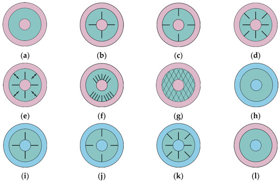
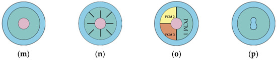
Figure 4.
Horizontal triplex-tube arrangements; (a) Case TTH-M; (b) Case TTH-ILF-M; (c) Case TTH-ELF-M; (d) Case TTH-ILF+ELF-M; (e) Case TTH-AF-M; (f) Case TTH-ILF+ELF-AT-M; (g) Case TTH-FO-M; (h) Case TTH-S; (i) Case TTH-ILF-S; (j) Case TTH-ELF-S; (k) Case TTH-ILF+ELF-M; (l) Case TTH-EH-M+S; (m) Case TTH-IH-M+S; (n) Case TTH-IH-ILF+ELF-M+S; (o) Case TTH-ILF-MP-M+S; (p) Case TTH-WT-S.
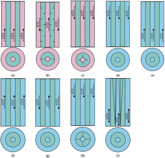
Figure 5.
Vertical triplex-tube arrangements; (a) Case TTV-B-T-M; (b) Case TTV-B-T-CF-M; (c) Case TTV-T-ILF-M; (d) Case TTV-T-S; (e) Case TTV-B-S; (f) Case TTV-T-BA-S; (g) Case TTV-TA-B-S; (h) Case TTV-T-ILF-S; (i) Case TTV-T-B-FR-S.
However, using the TT, it is possible to charge and discharge the TESU simultaneously. In this case, two solutions are possible. There is hot HTF in the inner tube and cold HTF in the annular gap or vice versa. Regardless of the TT TESU position and operating mode, different HTE techniques are applied. First of all, various types and arrangements of finning are used. In the case of vertical TT many combinations of hot and cold HTFs flow directions are possible. Thus, for example, the case TTH-ILF+ELF-S concerns a horizontal arrangement, in which the solidification process takes place and longitudinal fins are applied on the outer surface of the HTF tube and the inner surface of the middle tube. More details of the considered cases are discussed in the following, and also presented in Table 4 and Table 5.
Al-Abidi et al. [66] studied numerically the influence of longitudinal fin arrangement on charging TTH TESU with HTF flowing in an inner tube and outer annulus—Figure 4a,b,d. It was established that a partition of the middle tube with PCM into separate cells by longitudinal fins results in a substantial reduction in melting time. Al-Abidi et al. [67] conducted numerical calculations for similar geometry of TTH TESU but this time for the discharging process—Figure 4h,i,k. The results show that the case of separate PCM cells leads to the shortest solidification time. Mat et al. [68] investigated numerically the influence of longitudinal fin height on the charging performance of TTH TESU with HTF flowing in an inner tube and outer annulus—Figure 4a–d. The results show that the melting time decreases with fin height increase. Başal and Ünal [69] studied numerically the effect of inner tube, middle tube, and outer tube radii—Figure 4a—on the charging performance of TTH TESU. It was determined that for fixed PCM thickness and an outer tube radius the increase in inner tube radius results in a stored energy increase while melting time is constant. Abdulateef et al. [70] studied numerically the influence of straight and triangular longitudinal fins on the charging performance of TTH TESU—Figure 4a–d. It was determined that the shortest melting time was obtained for external finning by the use of triangular fins. Joybari et al. [71] investigated numerically the influence of free convection during the simultaneous charging and discharging performance of TTH TESU. Two heat transfer modes were investigated, namely with inner tube heating and external annulus cooling—Figure 4m, and with inner tube cooling and external annulus heating—Figure 4l. It was established that for the case of internal cooling and external heating, melted PCM affected the whole domain which resulted in maximum stored energy. Eslamnezhad and Rahimi [72] studied numerically the influence of rectangular longitudinal fin arrangement and shifting down the middle tube on the charging performance of TTH TESU—Figure 4d. It was found that depending on the position of the circumference, the fins should be placed on the inner tube or the middle tube. Moreover, shifting down the middle tube results in a reduction in melting time. Almsater et al. [73] investigated experimentally and numerically the charging and discharging performance of TTV TESU with a top inlet of HTF. Inner and middle tubes were connected by straight longitudinal fins, so the inner annulus with PCM was divided into separate cells. It was found that the melting time is generally shorter than the solidification time due to the effect of free convection. Mahdi et al. [74] studied numerically the influence of rectangular longitudinal fin height and number on the charging performance of TTH TESU—Figure 4d. It was determined that to achieve the shortest possible melting time, the top and bottom regions of the middle tube should be finned differently. The top fins should be shorter than the bottom fins and their number should be smaller. Wang et al. [75] studied numerically the discharging of TTH TESU with an inner HTF tube having a wavy cross section—Figure 4p. It was established that an increase in the amplitude of the inner tube results in a reduction of solidification time. Mahdi et al. [76] investigated numerically simultaneous charging and discharging performance of TTH TESU with inner tube heating and external annulus cooling. Additionally, internal and external longitudinal fins—straight and V-shaped, were considered—Figure 4n. It was established that the proposed fin arrangement allows a fast thermal response of the TESU. Alizadeh et al. [77] studied numerically the influence of longitudinal V-shaped fins attached to the middle tube on the discharging performance of TTH TESU—Figure 4j. It was shown that the length of the fin and branches angle are the essential parameters influencing the solidification time. Patel and Rathod [78] investigated numerically the influence of longitudinal straight fin arrangements on the charging and discharging performance of TTH TESU. Three locations of the fins were tested, namely internal, external and combined internal–external—Figure 4a–d,h–k. It was established that an internal–external fin arrangement is superior to other fin arrangements and results in a substantial reduction of melting and solidification time. Hosseini and Rahimi [79] studied numerically the influence of longitudinal straight fin arrangements on the charging performance of TTH TESU. Particularly the impact of fin height, the distance between fins, and fin position on the inner tube or middle tube were investigated—Figure 4f. It was established that a proper combination of these three components may result in a substantial reduction of melting time compared to the conventional case—Figure 4d. Zhao et al. [80] conducted a comparative numerical study on the effect of fin geometry—Figure 4d and metallic foam—Figure 4g, on the charging performance of DTH TESU. It was established that straight fins can be competitive with tree-shaped fins or metallic foams. Sun et al. [81] examined numerically the charging performance of TTV TESU with a bottom and top outer annulus HTF inlet—Figure 5a. Additionally, circular fins of different dimensions and various configurations in the middle tube with PCM were used. It was found that the application of circular fins both in in-line and staggered arrangements reduces the melting time substantially—Figure 5b. Mozafari et al. [82] investigated numerically the simultaneous charging and discharging performance of TTH TESU with inner tube heating and external annulus cooling. Additionally, the middle tube with various PCMs with different melting temperatures was divided into separate cells by longitudinal fins—Figure 4o. The second enhancement technique used was shifting the middle tube upward. It was established that the proposed application of two PCMs with different melting temperatures enhances both melting and solidification processes. It was also found that an upward shift of the middle tube results in a significant intensification of both energy storage and energy recovery. NematpourKeshteli et al. [83] studied numerically the influence of internal longitudinal fins and metal foams on the charging performance of TTH TESU—Figure 4b,g. Additionally, multilayer PCMs with different melting temperatures were placed in the middle tube. It was found that the use of both fins and metal foam resulted in a significant reduction in the melting time. The porosity of the metal foam is an important parameter. Ju et al. [84] examined numerically the frustum geometry of inner and middle tubes with various HTF flow arrangements on the discharging performance of TTV TESU—Figure 5d–g,i. It was determined that the solidification time for frustum geometry of inner and middle tubes is shorter than for conventional cylindrical design. Moreover, it was also shown that the maximum discharging rate was obtained for the top HTF inlet for both the tube and the outer annulus. Yan et al. [85] tested numerically the influence of internal longitudinal Y-shaped fins on the charging performance of TTH TESU—Figure 4e. From an extensive parametric study, it was found that for a certain combination of fin thickness and fin angle it is possible to significantly shorten the melting time.
Table 4.
Studies dealing with horizontal triplex-tube arrangements.
Table 4.
Studies dealing with horizontal triplex-tube arrangements.
| Executor(s) | Case (Figure 4) | Approach | Geometry | PCM | HTFt | HTFs | HTE |
|---|---|---|---|---|---|---|---|
| Al-Abidi et al. [66] | TTH-M TTH-ILF-M TTH-ILF+ELF-M | Numerical | dt,i = 50.8 mm ds,i = 150 mm dT,i = 200 mm L = 1000 mm | RT82 | Water | Water | Internal/external longitudinal straight fins |
| Al-Abidi et al. [67] | TTH-S TTH-ILF-S TTH-ILF+ELF-S | Numerical | dt,i = 50.8 mm ds,i = 150 mm dT,i = 200 mm L = 480 mm | RT82 | Water | Water | Internal/external longitudinal straight fins |
| Mat et al. [68] | TTH-M TTH-ILF-M TTH-ILF+ELF-M | Numerical | dt,i = 50.8 mm ds,i = 150 mm dT,i = 200 mm L = 480 mm | RT82 | Water | Water | Internal/external longitudinal straight fins |
| Başal and Ünal [69] | TTH-M | Numerical | dt,i = 20 mm ds,i = 40 mm dT,i = 100 mm L = 2000 mm | RT52 | Water | Water | Without |
| Abdulateef et al. [70] | TTH-M TTH-ILF-M TTH-ELF-M TTH-ILF+ELF-M | Experiment and numerical | dt,i = 76.2 mm ds,i = 381 mm dT,i = 500 mm L = 3000 mm | RT82 | Water | Water | Internal/external longitudinal straight and triangular fins |
| Joybari et al. [71] | TTH-IH-M+S TTH-EH-M+S | Numerical | dt,i = 51.02 mm ds,i = 124.64 mm | RT31 | Not specified tw = const. | Not specified tw = const | Without |
| Eslamnezhad an Rahimi [72] | TTH-ILF+ELF-M | Numerical | dt,i =50.8 mm ds,i = 150 mm dT,i = 200 mm L= 3000 mm | RT82 | Water | Water |
|
| Mahdi et al. [74] | TTH-ILF+ELF-M | Numerical | dt,i = 48.4 mm ds,i = 146 mm dT,i = 196 mm L = 500 mm | RT82 | Not specified tw = const. | Not specified tw = const | Internal/external longitudinal straight fins |
| Wang et al. [75] | TTH-WT-S | Numerical | 3 ≤ m ≤ 5.7 0.1 ≤ m ≤ 0.5 | Water Water-Al2O3 | Not specified tw = const. | Not specified tw = const. | Wavy shape of inner wall |
| Mahdi et al. [76] | TTH-IH-ILF+ELF-M+S | Numerical | Not specified | RT82 | HHTF Not specified tw = const. | CHTF Not specified tw = const. | Internal/external longitudinal straight and V-shaped fins |
| Alizadeh et al. [77] | TTH-ELF-S | Numerical | dt,i = 20 mm ds,i = 80 mm | Water | HHTF Not specified tw = const. | CHTF Not specified tw = const. | External longitudinal V-shaped fins |
| Patel and Rathod [78] | TTH-M TTH-S TTH-ILF-M TTH-ILF-S TTH-ELF-M TTH-ELF-S TTH-ILF+ELF-M TTH-ILF+ELF-S | Numerical | dt,i = 22 mm ds,i = 85 mm dT,i = 115 mm L = 2000 mm | RT50 | Not specified tw = const | HTF Not specified tw = const | Internal/external longitudinal straight fins |
| Hosseini and Rahimi [79] | TTH-ILF+ELF-M TTH-ILF+ELF-AT-M | Numerical | dt,i = 50.8 mm ds,i = 150 mm dT,i = 200 mm | RT82 | Not specified tw = const | Not specified tw = const | Internal/external longitudinal straight fins |
| Zhao et al. [80] | DTH-ILF+ELF-M DTH-FO-M | Numerical | dt =48.4 mm ds = 150 mm | RT82 | Not specified tw = const. | Not specified tw = const. |
|
| Mozafari et al. [82] | TTH-ILF-MP-M+S | Numerical | dt,i = 50.8 mm ds,i = 150 mm | RT55 RT60 RT65 | Not specified tw = const. | Not specified tw = const |
|
| NematpourKeshteli et al. [83] | TTH-ILF-M TTH-FO-M | Numerical | dt,i = 40 mm ds,i = 80 mm dT,i = 120 mm L = 2000 mm | RT31 RT35 RT42 | Water | Water |
|
| Yan et al. [85] | TTH-AF-M | Numerical | dt,i = 48.4 mm ds,i = 146 mm dT,i = 196 mm L = 500 mm | RT82 | Water | Water | Internal/external longitudinal Y-shaped fins |
Table 5.
Studies dealing with vertical triplex-tube arrangements.
Table 5.
Studies dealing with vertical triplex-tube arrangements.
| Executor(s) | Case (Figure 5) | Approach | Geometry | PCM | HTFt | HTFs | HTE |
|---|---|---|---|---|---|---|---|
| Almsater et al. [73] | TTV-T-ILF-M TTV-T-ILF-S | Experiment and numerical | dt,i = 50 mm ds,i = 150 mm dT,i = 200 mm H = 480 mm | Water | Dynalene HC-50 | Dynalene HC-50 | Longitudinal straight fins |
| Sun et al. [81] | TTV-B-T-M TTV-B-T-CF-M | Numerical | dt,i = 18 mm ds,i = 38 mm dT,i = 58 mm H = 250 mm | RT58 | Water | Water | Circular fins |
| Ju et al. [84] | TTV-T-S TTV-B-S TTV-T-BA-S TTV-TA-B-S TTV-T-B-FR-S | Numerical | dt,i,h = 18 mm ds,i,h = 38 mm dT,i, h = 58 mm H = 250 mm | RT35 | Frustum inner and middle tubes |
2.3. Multi-Tube Units
Multi-tube systems were divided into two main groups, namely horizontal (MTH)—Figure 6 and vertical (MTV)—Figure 7. In the case of MT systems, the tube bundle arrangement is important. In TESU, as in conventional shell and tube heat exchangers, in-line, staggered, and centrosymmetric layouts are used. Typically, regardless of the horizontal or vertical position and tube bundle layout, PCM is located on the shell side, while hot or cold HTF flows in tubes. However, in the case of MT systems, it is possible to charge and discharge the TESU simultaneously. Then, hot HTF flows in several tubes and cold HTF in the others. The MT TESU can also be designed like TT. When charging, PCM on the shell side is heated by the tube bundle and through the inner surface of the shell. During discharging process, PCM is cooled by the tube bundle and the inner surface of the shell. Various HTE techniques are applied. Different types and arrangements of finning are used. In the case of vertical MT TESU, many combinations of hot and cold HTFs flow directions are possible. Thus, for example, the case MTHL-TT-AT-M concerns a multi-tube horizontal TESU, with an in-line tube arrangement, in which the melting process takes place. Moreover, TESU is designed as TT with a non-conventional tube bundle layout. More details of the considered cases are discussed in the following, and also presented in Table 6 and Table 7.
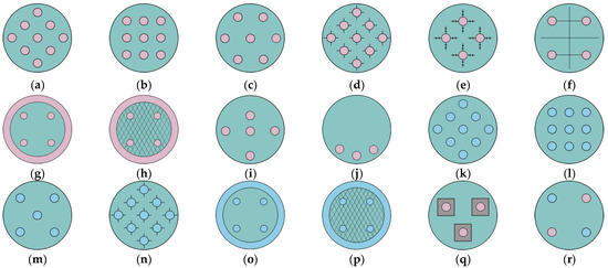
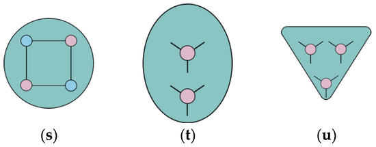
Figure 6.
Horizontal multi-tube arrangements; (a) Case MTHC-M; (b) Case MTHL-M; (c) Case MTHS-M; (d) Case MTHC-ILF-M; (e) Case MTHL-AF-M; (f) Case MTHL-WBT-M; (g) Case MTHL-TT-S; (h) Case MTHL-TT-FO-M; (i) Case MTHL-AT-M; (j) Case MTHL-AT-M; (k) Case MTHC-S; (l) Case MTHL-S; (m) Case MTHS-S; (n) Case MTHC-ILF-S; (o) Case MTHL-TT-S; (p) Case MTHL-TT-FO-S; (q) Case MTHS-P-M; (r) Case MTHL-M+S; (s) Case MTHL-WBT-M+S; (t) Case MTHL-SH-ILF-M; (u) Case MTHS-SH-ILF-M.
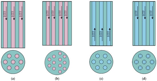
Figure 7.
Vertical multi-tube arrangements; (a) Case MTV-T-M; (b) Case MTV-B-AT-M; (c) Case MTV-B-S; (d) Case MTV-T-IFT-S.
Hendra et al. [86] investigated experimentally and numerically the charging process of MTHS TESU—Figure 6c. It was established that free convection was dominating the heat transfer mechanism and its occurrence depends on wall heat flux. Agyenim et al. [87] studied experimentally the charging and discharging performance of MTHS TESU—Figure 6c,m. It was established that MTHS TESU is superior to DTH-ILF and DTH-CF TESUSs for the charging process. The discharging process of DTH-ILF TESU was the most effective. In [88] Agyenim et al. examined experimentally MTHI TESU—Figure 6b,l. It was established that the MHTI TESU performance was very sensitive to HTF inlet temperature due to the balance between complete melting during charging process and subcooling during discharging process. Luo et al. [89] studied numerically the influence of tube arrangement, namely in-line—Figure 6b, staggered—Figure 6c, and centrosymmetric—Figure 6a—on the charging process of MTHC TESU. It was found that the most effective tube layout is centrosymmetric. Esapour et al. [90] studied numerically charging performance of MTHS and MTHL TESUs having TT geometry. It was determined that melting time decreased with an increase of tube number. In [91] Esapour et al. examined numerically the influence of tube bundle position in a shell during the charging performance of MTHL and MTHS TESUs using TT geometry. It was found that the melting time for the tube bundle placed in the bottom region is shorter than for the tube bundle situated in the top region of the shell. Al-Mudhafar et al. [92] studied numerically the charging process of MTHL TESU with and without longitudinal fins that connect HTF tubes—Figure 6f. It was shown that for MTHL TESU without webbed tubes, the melting rate is half of that with webbed tubes for the same time. Esapour et al. [93] investigated numerically the charging and discharging performance of MTH TESUs having TT geometry. Additionally, metal foam was applied in the middle tube with PCM—Figure 6h. It was found that metallic foam intensifies the solidification process more than the melting process. Raul et al. [94] investigated experimentally the discharging process of MTV TESU with top HTF inlet—Figure 7d. The HTF tubes were internally finned. Obtained results show that solidification time depended first of all on HFT inlet temperature and initial PCM temperature. The influence of HTF mass flow rate was of secondary importance. Sodhi et al. [95] studied numerically the influence of tube diameter and number of tubes on the charging and discharging performance of MTHC TESU—Figure 6a,k. It was established that for the same heat transfer area shorter melting and solidification time was obtained for tubes with smaller diameters. Abreha et al. [96] investigated numerically and experimentally the charging and discharging performance of MTHC TESU with longitudinal fins—Figure 6d,n. It was found that an increase in HTF temperature and mass flow rate results in a reduction of melting time. Park et al. [97] studied numerically the influence of tube bundle arrangement and the number of tubes on the charging process of MTHC—Figure 6a, MTHL—Figure 6b, and MTHS—Figure 6c, TESUs. A parameter—proportional to the melting time—is proposed. The parameter incorporates the main geometrical dimensions of the tube bundle and should be minimized. Kudachi et al. [98] investigated experimentally and numerically the charging process of MTHC TESU—Figure 6a. It was determined that numerically calculated temperature is distinctly higher than measured. This was explained by heat losses which were not included in the calculations. Mahdi et al. [99] studied numerically the tube bundle arrangement in the charging process of MTHL TESU. The results indicate that melting time is the shortest for tube bundles situated radially in the bottom region—Figure 6j. Yang et al. [100] studied numerically the charging and discharging performance of DTV TESU with a top and bottom HTF inlet—Figure 7a,c. An optimization procedure was carried out by the use of a variety of geometric, thermophysical, and economic parameters. According to Yang et al., an ε-NTU approach is a reliable design method of shell-and-tube TESU. Shaikh et al. [101] examined numerically the charging performance of MTHS and MTHL TESUs with TT geometry—Figure 6g. It was established that melting time decreases with increasing HTF temperature and the number of HTF tubes. Mahdavi et al. [102] studied numerically the simultaneous charging and discharging performance of MTHL TESU with webbed tubes—Figure 6s. Various configurations of hot and cold HTF tubes were examined. The most effective configuration was obtained for hot HTF tubes placed in the lower half of the shell. Qaiser et al. [103] conducted a comprehensive numerical and experimental study dealing with the charging process of MTH TESU. Various enhancement techniques were discussed, namely longitudinal Y-fin HTF tube, variable number of Y-fin HTF tubes, and variable position of Y-fin HTF tubes in a bundle. Finally, elliptic—Figure 6t and triangular—Figure 6u, cross-sections of the shell were examined. It was found that melting time decreases with the number of Y-fin HTF tubes. Second, the MTH TESU with elliptic and triangular cross-section shells performs better than conventional cylindrical shells. Song et al. [104] studied numerically the charging process of MTHL TESU with HTF tubes equipped with advanced fins—Figure 6e. It was established that tree-shaped fins impressively reduce melting time compared to smooth HTF tubes and longitudinally finned tubes. Vikas et al. [105] studied numerically the charging process of MTHL and MTHS TESUs for different tube bundle arrangements. It was determined that to achieve minimum melting time the HTF tubes should be arranged eccentrically. Moreover, the tubes placed in the upper half of the shell should be shifted to the center, while the tubes situated in the lower half of the shell should be shifted to the bottom—Figure 6i. Finally, it was established that the staggered tube arrangement is more efficient than the in-line layout at a given eccentricity. In [106] Vikas et al. investigated numerically the charging process of MTHL and MTHS TESUSs with longitudinally finned HTF tubes situated eccentrically in the shell. It was determined that the staggered finned tube arrangement with bigger eccentricity was the most efficient configuration. Wang et al. [107] studied numerically the charging process of DTV TESU with a bottom HTF inlet—Figure 7b. Additionally, the tube bundle was non-symmetrical. Obtained results show that modeling of heat transfer in MT TESU using the DT TESU approach and assuming the adiabatic condition at the outer shell side, significantly does not correspond to reality. This approach can, however, be substantially improved if the Neumann or Dirichlet boundary condition is used instead of the adiabatic condition. Zaglanmis et al. [108] investigated numerically the charging process of MTHL TESU—Figure 6b. Four different PCMs were tested. It was found that regardless of the type of PCM increase in HTF inlet temperature resulted in a decrease in melting time. Qaiser et al. [109] studied numerically the influence of a modified external cross-section of HTF tubes on the charging process of MTHS TESU—Figure 6q. The examined external cross-sections of the HTF tube were triangular, square, pentagonal, and hexagonal. Second, a triangular cross-section of the shell was discussed. It was found that HTF tubes with triangular external cross-sections and an oriented vertex pointing downwards improved the melting process unbeatably. Moreover, the combination of these tubes with shells with triangular cross-sections offered the best melting behavior. Fabrykiewicz and Cieśliński [110] studied experimentally the charging and discharging performance of MTHL and MTHS TESUs—Figure 6b,c. A variable number of HTF tubes, two pitch ratios, and different tube positions in a shell were examined. It was established that the shortest melting and solidification time was obtained for the tube bundle with the highest tube number, lower pitch ratio, and staggered tube arrangement.
Table 6.
Studies dealing with horizontal multi-tube arrangements.
Table 6.
Studies dealing with horizontal multi-tube arrangements.
| Executor(s) | Case (Figure 6) | Approach | Geometry | PCM | HTF | HTE |
|---|---|---|---|---|---|---|
| Hendra et al. [86] | MTHS-M | Experiment and numerical | dt,i = 12.7 mm ds = 262.5 mm L = 1000 mm Staggered | Mikro | Water | Without |
| Agyenim et al. [87] | MTHS-M MTHS-S | Experiment | dt,o = 23 mm ds = 146.4 mm L = 937.5 mm Staggered | Erythritol | Not specified tin = 140 °C | Without |
| Agyenim et al. [88] | MTHL-M MTHL-S | Experiment | dt,i = 23 mm ds = 146 mm L = 1000 mm In-line | Erythritol | Not specified 130 ≤ tin ≤ 140 °C | Without |
| Luo et al. [89] | MTHC-M | Numerical | dt = R/6 ds = 2R In-line Staggered Centrosymmetric | Pr = 0.1 Pr = 0.02 | Not specified tw = const. | Without |
| Esapour et al. [90] | MTHL-TT-M | Numerical | 15 ≤ dt,i [mm] ≤ 21.2 ds,i = 95 mm dT,i = 125 mm L = 1000 mm In-line | RT35 | Water | Triplex-tubes |
| Esapour et al. [91] | Numerical | 15 ≤ dt,i [mm] ≤ 21.2 ds,i = 95 mm dT,i = 125 mm L = 1000 mm In-line | RT35 | Water | Triplex-tubes | |
| Al-Mudhafar et al. [92] | MTHL-M MTHL-WBT-M | Numerical | dt,i = 20 mm ds = 150 mm L = 1000 mm In-line | RT82 | Water | Webbed tubes |
| Esapour et al. [93] | MTHL-TT-FO-M MTHL-TT-FO-S | Numerical | 15 ≤ dt,i [mm] ≤ 21.2 ds,i = 95 mm dT,i = 125 mm L = 1000 mm In-line Staggered | RT35 | Water |
|
| Sodhi et al. [95] | MTHC-M MTHC-S | Numerical | 8.7 ≤ dt,i [mm] ≤ 21.4 227.7 ≤ ds,i [mm] ≤ 237.14 Centrosymmetric | NaNO3 | Not specified tw = const. | Without |
| Abreha et al. [96] | MTHC-ILF-M MTHC-ILF-S | Numerical and experiment | dt,i = 17 mm ds = 240 mm Centrosymmetric | Erythritol | Cooking waste oil | Internal longitudinal straight fins |
| Park et al. [97] | MTHC-M MTHL-M MTHS-M | Numerical | 2.25 ≤ dt,i [mm] ≤ 18 38.46 ≤ ds,i [mm] ≤ 41.98 In-line Staggered Centrosymmetric | N-eicosane | Not specified tw = const. | Without |
| Kudachi et al. [98] | MTHC-M | Experiment and numerical | dt,i = 14 mm ds = 108.2 mm L = 600 mm Centrosymmetric | OM65 | Water | Without |
| Mahdi et al. [99] | MTHL-AT-M | Numerical | dt = 10 mm ds = 70 mm L = 600 mm In-line | Lauric acid | Not specified tw = const. | Without |
| Shaikh et al. [101] | MTHL-TT-M | Numerical | 15 ≤ dt,i [mm] ≤ 30 ds = 150 mm dT,i = 200 mm L = 1000 mm In-line | KNO3/NaNO3 salt | Oil | Triplex-tubes |
| Mahdavi et al. [102] | MTHL-M+S MTHL-WBT-M+S | Numerical | dt = 15 mm ds = 70 mm In-line | RT82 | Not specified tw = const. | Fins |
| Qaiser et al. [103] | MTH-AT-ILF-M MTH-SH-ILF-M | Numerical and experiment | 14.355 ≤ dt,i [mm] ≤ 22.698 ds = 121 mm | Stearic acid | Water | Internal longitudinal fins |
| Song et al. [104] | MTHL-AF-M | Numerical | dt = 18 mm ds = 304 mm L = 400 mm In-line | Lauric acid | Not specified tw = const. | Internal longitudinal straight and tree-shaped fins |
| Vikas et al. [105] | MTHL-AT-M MTHS-AT-M | Numerical | dt,o = 12.5 mm ds = 100 mm In-line Staggered | Paraffin wax | Not specified tw = const. | Radial eccentricity of HTF tubes |
| Vikas et al. [106] | MTHL-AT-M | Numerical | dt,o = 12.5 mm ds = 100 mm In-line Staggered | Paraffin wax | Not specified tw = const. |
|
| Zaglanmis et al. [108] | MTHL-M | Numerical | dt,o = 10 mm ds = 80 mm L = 500 mm In-line | RT35 n-eicosane n-octadecane gallium | Water | Without |
| Qaiser et al. [109] | MTHS-P-M | Numerical | dt,o = 16 mm ds = 121 mm Staggered | Stearic acid | Not specified tw = const. | Polygon shape of external cross-section of HTF tubes |
| Fabrykiewicz and Cieśliński [110] | MTHL-M MTHS-M MTHL-S MTHS-S | Experiment | dt,i = 4 mm ds,i = 70 mm L = 400 mm In-line Staggered | LTP56 RT54HC P1808 | Water | Without |
Table 7.
Studies dealing with vertical multi-tube arrangements.
Table 7.
Studies dealing with vertical multi-tube arrangements.
| Executor(s) | Case (Figure 7) | Approach | Geometry | PCM | HTF | HTE |
|---|---|---|---|---|---|---|
| Raul et al. [94] | MTV-T-IFT-S | Experiment | dt,i = 10.4 mm ds = 100 mm H = 800 mm | A164 | Hytherm 600 | Longitudinal straight fins inside HTF |
| Yang et al. [100] | MTV-T-M MTV-B-S | Optimization | dt,o = 17.2 mm | PCMs with specified tm and hm | Not specified tin = 68 °C | Without |
| Wang et al. [107] | MTV-B-AT-S | Numerical | dt,i = 4.6 mm ds = 172.7 mm H = 508 mm | n-octadekane | Air | Non-symmetrical tube bundle |
3. Discussion
The basic geometry that is considered as PCM TESU is the DT system. This is due to the fact that it is the simplest geometry for both numerical considerations and experimental research. Very often, the results for DT unit are benchmark for more complex systems, such as TT or MT systems. In particular, MTV systems are numerically modeled using only a single DT unit. This approach results in a significant reduction in computational time. However, as shown in [106], the assumption of the adiabatic condition at the outer DT shell side gives incorrect results.
Figure 8 shows the effect of different types of fins on the average PCM temperature for the DTH TESU charging and discharging cycle.
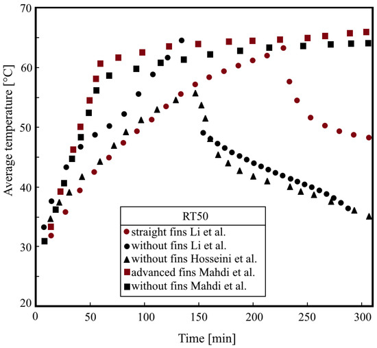
Figure 8.
Influence of fins on PCM temperature in DTH TESUs [34,59,62].
The results of Li et al. [62] and Mahdi et al. [59] clearly show that the use of fins causes intensification of heat transfer, which results in higher PCM temperatures during the charging process and lower PCM temperatures during discharge. It is worth noting that the calculation results of Li et al. [62] satisfactorily reflect the experimental data of Hosseini et al. [34] for DTH TESU without fins. On the other hand, the results of calculations by Mahdi et al. [59] overestimated experimental data by Hosseini et al. [34], which results from the different lengths of the TESU, as well as from the assumed boundary condition (tw = 70 °C), while the experiment was carried out for the HTF temperature at the inlet t = 70 °C. The advantage in the intensification of heat transfer of longitudinal branch-shaped fins considered by Mahdi et al. [59] should also be emphasized, above the straight longitudinal fins used by Li et al. [62].
Figure 9 illustrates the influence of tilt angle and location of HTF inlet on the PCM temperature in the middle section of DTH or DTV TESU.
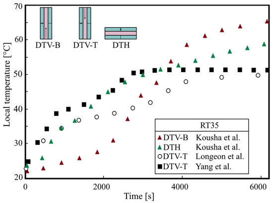
Figure 9.
Influence of angle of inclination on PCM temperature location of HTF inlet [33,49,52].
According to the research by Kousha et al. [52] for the same HTF inlet temperature t = 80 °C in the initial loading period, the PCM temperature in the middle section of the DTH TESU is higher than for the DTV TESU—Figure 9. However, after about 3000 s the impact of the location of the HTF inlet is negligible. Figure 9 also shows the results of research by Longeon et al. [33] for DTV TESU and HTF inlet at the top. Clearly, the lower PCM temperature in the middle section compared to the results of Kousha et al. [52] is mainly due to the lower HTF temperature at the inlet, i.e., t = 52 °C. In turn, the results of Yang et al. [49] confirm the positive effect of finning on the intensification of heat transfer during the charging process. The PCM temperature in the middle section using circular fins is higher than in the study by Kousha et al. [52], even though the HTF temperature at the inlet was only t = 52 °C.
The Frustum shell seems to be an effective alternative to the DTV cylindrical shell. As shown in Figure 10, the PCM melting process is more intense than in the case of a cylindrical shell.
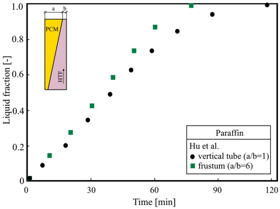
Figure 10.
Influence of DTV shell shape on melting process [42].
The TT TESU seems to be an interesting alternative to DT TESU due to shorter charging and discharging times with a small complexity of geometry. In addition, the use of TT TESU gives the opportunity to simultaneously store and download thermal energy.
Figure 11 shows a comparison of PCM average temperature distribution against time in DTH and TTH. As shown in Figure 11, to achieve the same average PCM temperature, in the case of TTH the inlet temperature of HTF needed is 50 °C, while for DT the HTF inlet temperature must be as high as 70 °C. Much higher average PCM temperature in the case of the study by Kousha et al. [52] for DTH compared to the results of Esapour et al. [90] is due to the significantly higher HTF inlet temperature. In the case of Kousha et al. [52] it was 70 °C, while for Esapoura et al. [90] it was 50 °C.
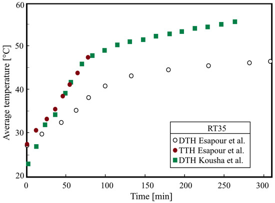
Figure 11.
Comparison of PCM temperature for DTH and TTH [52,90].
Figure 12 shows the influence of the HTE technique on the melting process in TTH TESUs. The highest liquid fraction rate was obtained for Cu metallic foam and fins made of carbon fiber with a very high axial thermal conductivity—900 W/(mK). The use of external triangular fins—for the same HTF inlet temperature (90 °C)—gave significantly lower liquid fraction values.
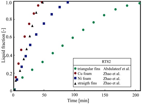
Figure 12.
Liquid fraction distribution for TTH TESU [70,80].
However, large-scale thermal energy storage will only be possible with MT TESUs. The work carried out so far concerns mostly systems with a very small number of tubes and a small amount of PCM. Test results obtained for small TESUs cannot be used in the design of large-scale systems. On the basis of the research carried out so far, it is difficult to clearly state which of the tube arrangement, namely in-line, staggered, or centrosymmetric, is the most advantageous from the point of view of TESU efficiency. The same applies to the pitch ratio and filling of the shell, defined as a ratio of the volume of the tube bundle to the shell volume.
Figure 13 shows the results of the numerical calculations of liquid fraction for the MTH TESU and in-line tube arrangement. As shown in Figure 13, the results of Park et al. [97] are qualitatively consistent with the results of Zanglanmis et al. [108] for n-eicosane as PCM. The higher liquid fraction values obtained by Park et al. [97]—despite a bundle with a larger number of tubes, they may result from a higher HTF temperature, which in the case of Park et al. [97] was 80 °C., while in Zaglanmis et al. [108] was 75 °C. The calculations of Zaglanmis et al. [108] show that for the tested MTH TESU, the most favorable PCM is gallium, and the least favorable is n-eicosane.
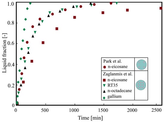
Figure 13.
Liquid fraction distribution for MTH TESU [97,108].
Figure 14 shows the melting fraction distribution for the three discussed TESU designs, i.e., DTH, TTH, and MTH.
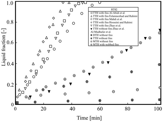
Figure 14.
Comparison of liquid fraction distribution for DTH, TTH, and MTH TESUs [66,72,76,79,80,92].
As shown in Figure 14, the results obtained by Al-Abidi et al. [66], Eslamnezhad and Rahimi [72], Mahdi et al. [76], Hosseini and Rahimi [79], and Zhao et al. [80] for TTH TESU with internal and external longitudinal fins are qualitatively consistent. Liquid fraction values calculated by Al-Mudhafar et al. [92] are much lower than those of other authors, but they were obtained for pipes without fins. The results of Al-Mudhafar et al. [92] for MTH with webbed tubes show good qualitative and quantitative agreement with the data of Zhao et al. [80] for TTH without fins. Unfortunately, no clear conclusions can be drawn as the tested TESUs did not contain the same amount of PCM.
The research carried out so far shows that the most advantageous way to intensify heat transfer in PCM systems is the use of fins on the surface of HTF tubes, fins on the surface of the shell, or the use of both finning methods simultaneously. Surface fining turned out to be more effective than the use of metal foams or screens. The fins of extremely complex shapes are considered, too. The arrangement of the tubes is also very important. However, it should be remembered that the tube layout, which is beneficial for the charging (melting) process, is most often not effective during the TESU discharging (solidification) process.
As shown in Table 1, Table 2, Table 3, Table 4, Table 5, Table 6 and Table 7, the majority of the published works are numerical studies. There is no doubt that in order to verify the results presented in them, systematic experimental research should be carried out.
The authors of numerical papers usually limit themselves to validating their models by referring to other numerical models or the least complex experimental cases. It happens that authors of numerical models carry out validation for a given design, but use a different PCM. Knowing how different the thermophysical properties of PCM [111,112] are and how complex the problem of determining the thermophysical properties of PCM [113] is, special attention should be paid to this issue.
The most prospective shell-and-tube TESUs seem to be systems with high-conductivity fins of different heights and spacing, dedicated PCM or several PCMs, and additionally with a modified jacket.
4. Conclusions
In order to unambiguously verify the results of numerical and experimental tests, in addition to geometrical conditions, thermal conditions should be precisely met, especially the HTF temperature at the inlet. In addition, the thermophysical properties of the PCM should be the same.
In most of the published works, the authors focused on the methods of intensifying the melting process, and after all, energy storage is a multiple charging and discharging cycle. The thermo-energy assessment should therefore cover the entire energy storage cycle, including charging, storage, and discharging. So far, no universal methodology for determining comparative criteria has been proposed.
Funding
This research received no external funding.
Conflicts of Interest
The authors declare no conflict of interest.
Nomenclature
| d | Diameter | (m) |
| H | Height | (m) |
| L | Length | (m) |
| m | Shape factor | (-) |
| S | Surface area of PCM zone | (m2) |
| t | Temperature | (°C) |
| Greek letters | ||
| θ | Inclination angle | (°) |
| Subscripts | ||
| h | Hydraulic diameter | |
| i | Inside | |
| o | Outside | |
| s | Shell | |
| t | Tube | |
| T | Third tube | |
| w | Wall | |
| Abbreviations | ||
| AF | Advanced fins | |
| AT | Tube bundle arrangement | |
| B | Bottom HTF inlet | |
| BA | Bottom annulus HTF inlet | |
| CF | Circular fins | |
| DT | Double-tube | |
| DTH | Double-tube horizontal | |
| DTI | Double-tube inclined | |
| DTV | Double-tube vertical | |
| E | Eccentricity | |
| EH | External annulus heating | |
| EL | Elliptical | |
| ELF | External longitudinal fins | |
| FO | Foam | |
| FR | Frustum shell or HTF tube | |
| HTE | Heat transfer enhancement | |
| HTF | Heat transfer fluid | |
| HTFE | Heat transfer fluid enhancement | |
| IFT | Internally finned heat transfer fluid tube | |
| IH | Internal tube heating | |
| ILF | Internal longitudinal fins | |
| ILF+ELF | Internal and external longitudinal fins | |
| M | Melting | |
| MP | Multiple PCMs | |
| M+S | Simultaneous melting and solidification | |
| MT | Multi-tube | |
| MTHC | Multi-tube horizontal centrosymmetric | |
| MTHL | Multi-tube horizontal in-line | |
| MTHS | Multi-tube horizontal staggered | |
| MTV | Multi-tube vertical | |
| S | Solidification | |
| SC | Screen | |
| SHE | Elliptical shell | |
| SHT | Triangular shell | |
| SP | PCM in shell side | |
| P | Modified shape of external cross-section of HTF tube | |
| T | Top HTF inlet | |
| TA | Top annulus HTF inlet | |
| TT | Triplex-tube | |
| TESU | Thermal energy storage unit | |
| TTH | Triplex-tube horizontal | |
| TTV | Triplex-tube vertical | |
| VG | Vortex generator inside HTF tube | |
| WT | Wavy HTF tube | |
| WBT | Webbed tubes |
References
- Letcher, T.M. Storing Energy with Special Reference to Renewable Energy Sources; Elsevier: Amsterdam, The Netherlands, 2016. [Google Scholar]
- Cabeza, L.F. (Ed.) Advances in Thermal Energy Storage Systems: Methods and Applications; Elsevier Ltd.: Amsterdam, The Netherlands, 2015. [Google Scholar]
- Fredi, G.; Dorigato, A.; Fambri, L.; Pegoretti, A. Evaluating the multifunctional performance of structural composites for thermal energy storage. Polymers 2021, 13, 3108. [Google Scholar] [CrossRef] [PubMed]
- Dhaidan, N.S.; Khodadadi, J.M. Improved performance of latent heat energy storage systems utilizing high thermal conductivity fins: A review. J. Renew. Sustain. Energy 2017, 9, 034103. [Google Scholar] [CrossRef]
- Ahmed, S.; Abderrahmane, A.; Saeed, A.M.; Guedri, K.; Mourad, A.; Younis, O.; Botmart, T.; Shah, N.A. Melting enhancement of PCM in a finned tube latent heat thermal energy storage. Sci. Rep. 2022, 12, 11521. [Google Scholar] [CrossRef]
- Fukai, J.; Hamada, Y.; Morozumi, Y.; Miyatake, O. Effect of carbon-fiber brushes on conductive heat transfer in phase change materials. Int. J. Heat Mass Transf. 2002, 45, 4781–4792. [Google Scholar] [CrossRef]
- Manikandan, K.S.; Sivasankar, B.; Kumar, V.S.; Sukumar, V.; Kumaresan, G. Experimental Investigation Of Latent Heat Thermal Energy Storage Characteristics Of Paraffin/Carbon Fiber Composite As Phase Change Material. Int. J. Curr. Res. 2011, 3, 211–214. [Google Scholar]
- Baumeister, J.; Weise, J.; Myslicki, S.; Kieseritzky, E.; Lindenberg, G. PCM-Based Energy Storage System with High Power Output Using Open Porous Aluminum Foams. Energies 2020, 13, 6198. [Google Scholar] [CrossRef]
- Cui, W.; Si, T.; Li, X.; Li, X.; Lu, L.; Ma, T.; Wang, Q. Heat transfer enhancement of phase change materials embedded with metal foam for thermal energy storage: A review. Renew. Sust. Energ. Rev. 2022, 169, 112912. [Google Scholar] [CrossRef]
- Yu, J.; Yang, Y.; Yang, X.; Kong, Q.; Yanhua, L.; Yan, J. Effect of porous media on the heat transfer enhancement for a thermal energy storage unit. Energy Procedia 2018, 152, 984–989. [Google Scholar] [CrossRef]
- Sweidan, A.H.; Heider, Y.; Markert, B. Simulation of PCM-saturated porous solid matrix for thermal energy storage using the phase-field method. Proc. Appl. Math. Mech. 2018, 18, e201800433. [Google Scholar] [CrossRef]
- Mabrouk, R.; Naji, H.; Dhahri, H.; Younsi, Z. On Numerical Modeling of Thermal Performance Enhancement of a Heat Thermal Energy Storage System Using a Phase Change Material and a Porous Foam. Computation 2022, 10, 3. [Google Scholar] [CrossRef]
- Albaldawi, R.; Shyaa, A.; Ban, M.H.H. Experimental Study on the Effect of Insertion of Copper Lessing Rings in Phase Change Material (PCM) on the Performance of Thermal Energy Storage Unit. Al Khwarizmi Eng. J. 2015, 11, 60–72. [Google Scholar]
- Velraj, R.; Seeniraj, R.V.; Hafner, B.; Faber, C.; Schwarzer, K. Heat transfer enhancement in a latent heat storage system. Sol. Energy 1999, 65, 171–180. [Google Scholar] [CrossRef]
- Lingamneni, S.; Asheghi, M.; Goodson, K.E. A parametric study of Microporous Metal Matrix-Phase Change Material composite heat spreaders for transient thermal applications. In Proceedings of the Fourteenth Intersociety Conference on Thermal and Thermomechanical Phenomena in Electronic Systems, Orlando, FL, USA, 27–30 May 2014; 2014; pp. 870–875. [Google Scholar] [CrossRef]
- Shastry, D.M.C.; Arunachala, U.C. Thermal management of photovoltaic module with metal matrix embedded PCM. J. Energy Storage 2020, 28, 101312. [Google Scholar] [CrossRef]
- Mahmoud, S.; Tang, A.; Toh, C.; AL-Dadah, R.; Soo, S.L. Experimental investigation of inserts configurations and PCM type on the thermal performance of PCM based heat sinks. Appl. Energy 2013, 112, 1349–1356. [Google Scholar] [CrossRef]
- Andreozzi, A.; Buonomo, B.; Ercole, D.; Manca, O. Phase Change Materials (PCMs) in a honeycomb system for solar energy applications. Int. J. Heat Technol. 2017, 35, S472–S477. [Google Scholar] [CrossRef]
- Klemm, T.; Meinert, J.; Goehler, H.; Hauser, R.; Kieback, B. PCM-filled metallic hollow spheres for high power thermal energy storage. In Proceedings of the Cellular Materials—CellMat 2014, Dresden, Germany, 22–24 October 2014. [Google Scholar]
- Li, M.J.; Jin, B.; Ma, Z.; Yuan, F. Experimental and numerical study on the performance of a new high-temperature packed-bed thermal energy storage system with macroencapsulation of molten salt phase change material. Appl. Energy 2018, 221, 1–15. [Google Scholar] [CrossRef]
- Huang, X.; Zhu, C.; Lin, Y.; Fang, G. Thermal properties and applications of microencapsulated PCM for thermal energy storage: A review. Appl. Therm. Eng. 2019, 147, 841–855. [Google Scholar] [CrossRef]
- Shchukina, E.M.; Graham, M.; Zheng, Z.; Shchukin, D.G. Nanoencapsulation of phase change materials for advanced thermal energy storage systems. Chem. Soc. Rev. 2018, 47, 4156. [Google Scholar] [CrossRef]
- Hayat, M.A.; Chen, Y. A Brief Review on Nano Phase Change Material-Based Polymer Encapsulation for Thermal Energy Storage Systems. In Energy and Sustainable Futures; Mporas, I., Kourtessis, P., Al-Habaibeh, A., Asthana, A., Vukovic, V., Senior, J., Eds.; Springer: Cham, Switzerland, 2021. [Google Scholar]
- Algarni, M.; Alazwari, M.A.; Safaei, M.R. Optimization of Nano-Additive Characteristics to Improve the Efficiency of a Shell and Tube Thermal Energy Storage System Using a Hybrid Procedure: DOE, ANN, MCDM, MOO, and CFD Modeling. Mathematics 2021, 9, 3235. [Google Scholar] [CrossRef]
- Punniakodi, B.M.S.; Senthil, R. Recent developments in nano-enhanced phase change materials for solar thermal storage. Sol. Energy Mater. Sol. Cells. 2022, 238, 111629. [Google Scholar] [CrossRef]
- Lacroix, M. Numerical simulation of a shell-and-tube latent heat thermal storage unit. Sol. Energy 1993, 50, 357–367. [Google Scholar] [CrossRef]
- Ettouney, H.; Alatiqi, I.; Al-Sahali, M.; Al-Ali, S. Heat transfer enhancement by metal screens and metal spheres in phase change energy storage systems. Renew. Energy 2004, 29, 841–860. [Google Scholar] [CrossRef]
- Trp, A. An experimental and numerical investigation of heat transfer during technical grade paraffin melting and solidification in a shell-and-tube latent thermal energy storage unit. Sol. Energy 2005, 79, 648–660. [Google Scholar] [CrossRef]
- Adine, H.A.; El Qarnia, H. Numerical analysis of the thermal behaviour of a shell-and-tube heat storage unit using phase change materials. Appl. Math. Model. 2009, 33, 2132–2144. [Google Scholar] [CrossRef]
- Chiu, J.N.W.; Martin, V. Submerged finned heat exchanger latent heat storage design and its experimental verification. Appl. Energy 2012, 93, 507–516. [Google Scholar] [CrossRef]
- Avci, M.; Yazici, M.Y. Experimental study of thermal energy storage characteristics of a paraffin in a horizontal tube-in-shell storage unit. Energy Convers. Manag. 2013, 73, 271–277. [Google Scholar] [CrossRef]
- Solomon, G.R.; Velraj, R. Analysis of the heat transfer mechanisms during energy storage in a Phase Change Material filled vertical finned cylindrical unit for free cooling application. Energy Convers. Manag. 2013, 75, 466–473. [Google Scholar] [CrossRef]
- Longeon, M.; Soupart, A.; Fourmigué, J.F.; Bruch, A.; Marty, P. Experimental and numerical study of annular PCM storage in the presence of natural convection. Appl. Energy 2013, 112, 175–184. [Google Scholar] [CrossRef]
- Hosseini, M.J.; Rahimi, M.; Bahrampoury, R. Experimental and computational evolution of a shell and tube heat exchanger as a PCM thermal storage system. Int. Commun. Heat Mass Transf. 2014, 50, 128–136. [Google Scholar] [CrossRef]
- Kibria, M.A.; Anisur, M.R.; Mahfuz, M.H.; Saidur, R.; Metselaar, I.H.S.C. Numerical and experimental investigation of heat transfer in a shell and tube thermal energy storage system. Int. Commun. Heat Mass Transf. 2014, 53, 71–78. [Google Scholar] [CrossRef]
- Yazici, M.Y.; Avci, M.; Aydin, O.; Akgun, M. On the effect of eccentricity of a horizontal tube-in-shell storage unit on solidification of a PCM. Appl. Therm. Eng. 2014, 64, 1–9. [Google Scholar] [CrossRef]
- Liu, C.; Groulx, D. Experimental study of the phase change heat transfer inside a horizontal cylindrical latent heat energy storage system. Int. J. Therm. Sci. 2014, 82, 100–110. [Google Scholar] [CrossRef]
- Tao, Y.B.; He, Y.L. Numerical study on performance enhancement of shell-and-tube latent heat storage unit. Int. Commun. Heat Mass Transf. 2015, 67, 147–152. [Google Scholar] [CrossRef]
- Rathod, M.K.; Banerjee, J. Thermal performance enhancement of shell and tube Latent Heat Storage Unit using longitudinal fins. Appl. Therm. Eng. 2015, 75, 1084–1092. [Google Scholar] [CrossRef]
- Sciacovelli, A.; Gagliardi, F.; Verda, V. Maximization of performance of a PCM latent heat storage system with innovative fins. Appl. Energy 2015, 137, 707–715. [Google Scholar] [CrossRef]
- Seddegh, S.; Wang, X.; Henderson, A.D. Numerical investigation of heat transfer mechanism in a vertical shell and tube latent heat energy storage system. Appl. Therm. Eng. 2015, 87, 698–706. [Google Scholar] [CrossRef]
- Hu, Z.; Li, A.; Gao, R.; Yin, H. Enhanced heat transfer for PCM melting in the frustum-shaped unit with multiple PCMs. J. Therm. Anal. Calorim. 2015, 120, 1407–1416. [Google Scholar] [CrossRef]
- Darzi, A.A.R.; Jourabian, M.; Farhadi, M. Melting and solidification of PCM enhanced by radial conductive fins and nanoparticles in cylindrical annulus. Energy Convers. Manag. 2016, 118, 253–263. [Google Scholar] [CrossRef]
- Tao, Y.B.; Carey, V.P. Effects of PCM thermophysical properties on thermal storage performance of a shell-and-tube latent heat storage unit. Appl. Energy 2016, 179, 203–210. [Google Scholar] [CrossRef]
- Yuan, Y.; Cao, X.; Xiang, B.; Du, Y. Effect of installation angle of fins on melting characteristics of annular unit for latent heat thermal energy storage. Sol. Energy 2016, 136, 365–378. [Google Scholar] [CrossRef]
- Han, G.S.; Ding, H.S.; Huang, Y.; Tong, L.G.; Ding, Y.L. A comparative study on the performances of different shell-and-tube type latent heat thermal energy storage units including the effects of natural convection. Int. Commun. Heat Mass Transf. 2017, 88, 228–235. [Google Scholar] [CrossRef]
- Kuboth, S.; König-Haagen, A.; Brüggemann, D. Numerical Analysis of Shell-and-Tube Type Latent Thermal Energy Storage Performance with Different Arrangements of Circular Fins. Energies 2017, 10, 274. [Google Scholar] [CrossRef]
- Tao, Y.B.; Liu, Y.K.; He, Y.L. Effects of PCM arrangement and natural convection on charging and discharging performance of shell-and-tube LHS unit. Int. J. Heat Mass Transf. 2017, 115 Pt B, 99–107. [Google Scholar] [CrossRef]
- Yang, X.; Lu, Z.; Bai, Q.; Zhang, Q.; Jin, L.; Yan, J. Thermal performance of a shell-and-tube latent heat thermal energy storage unit: Role of annular fins. Appl. Energy 2017, 202, 558–570. [Google Scholar] [CrossRef]
- Seddegh, S.; Joybari, M.M.; Wang, X.; Haghighat, F. Experimental and numerical characterization of natural convection in a vertical shell-and-tube latent thermal energy storage system. Sustain. Cities Soc. 2017, 35, 13–24. [Google Scholar] [CrossRef]
- Pizzolato, A.; Sharma, A.; Maute, K.; Sciacovelli, A.; Verda, V. Topology optimization for heat transfer enhancement in Latent Heat Thermal Energy Storage. Int. J. Heat Mass Transf. 2017, 113, 875–888. [Google Scholar] [CrossRef]
- Kousha, N.; Hosseini, M.J.; Aligoodarz, M.R.; Pakrouh, R.; Bahrampoury, R. Effect of inclination angle on the performance of a shell and tube heat storage unit—An experimental study. Appl. Therm. Eng. 2017, 112, 1497–1509. [Google Scholar] [CrossRef]
- Mehta, D.S.; Solanki, K.; Rathod, M.K.; Banerjee, J. Thermal performance of shell and tube latent heat storage unit: Comparative assessment of horizontal and vertical orientation. J. Energy Storage 2019, 23, 344–362. [Google Scholar] [CrossRef]
- Dukhan, W.A.; Dhaidan, N.S.; Al-Hattab, T.A. Experimental Investigation of the Horizontal Double Pipe Heat Exchanger Utilized Phase Change Material. IOP Conf. Ser. Mater. Sci. Eng. 2020, 671, 012148. [Google Scholar] [CrossRef]
- Yu, C.; Wu, S.; Huang, Y.; Yao, F.; Liu, X. Charging performance optimization of a latent heat storage unit with fractal tree-like fins. J. Energy Storage 2020, 30, 101498. [Google Scholar] [CrossRef]
- Huang, Y.; Sun, Q.; Yao, F.; Zhang, C. Performance optimization of a finned shell-and-tube ice storage unit. Appl. Therm. Eng. 2020, 167, 114788. [Google Scholar] [CrossRef]
- Liu, J.; Liu, Z.; Nie, C. Phase transition enhancement through circumferentially arranging multiple phase change materials in a concentric tube. J. Energy Storage 2021, 40, 102672. [Google Scholar] [CrossRef]
- Sodhi, G.S.; Kumar, V.; Muthukumar, P. Design assessment of a horizontal shell and tube latent heat storage system: Alternative to fin designs. J. Energy Storage 2021, 44 Pt A, 103282. [Google Scholar] [CrossRef]
- Mahdi, M.S.; Khadom, A.A.; Mahood, H.B.; Campbell, A.N. Numerical Study of Latent Heat Storage Unit Thermal Performance Enhancement Using Natural Inspired Fins. IOP Conf. Ser. Mater. Sci. Eng. 2021, 1076, 012028. [Google Scholar] [CrossRef]
- Andrzejczyk, R.; Kowalczyk, T.; Kozak, P.; Muszyński, T. Experimental and theoretical study of a vertical tube in shell storage unit with biodegradable PCM for low temperature thermal energy storage applications. Appl. Therm. Eng. 2021, 183 Pt 1, 116216. [Google Scholar] [CrossRef]
- Ye, W.; Khodadadi, J.M. Effects of arrow-shape fins on the melting performance of a horizontal shell-and-tube latent heat thermal energy storage unit. J. Energy Storage 2022, 54, 105201. [Google Scholar] [CrossRef]
- Li, F.; Abed, A.M.; Naghdi, O.; Nasajpour-Esfahani, N.; Hamedi, S.; Al Mashhadani, Z.I.; Fazilati, M.A.; Mohammed, B.M.; Hadrawi, S.K.; Smaisim, G.F.; et al. The numerical investigation of the finned double-pipe phase change material heat storage system equipped with internal vortex generator. J. Energy Storage 2022, 55 Pt A, 105413. [Google Scholar] [CrossRef]
- Ao, C.; Yan, S.; Hu, W.; Zhao, L.; Wu, Y. Heat transfer analysis of a PCM in shell-and-tube thermal energy storage unit with different V-shaped fin structures. Appl. Therm. Eng. 2022, 216, 119079. [Google Scholar] [CrossRef]
- Shakrina, G.; Rivera-Tinoco, R.; Bouallou, C. Numerical investigation and extensive parametric analysis of cryogenic latent heat shell and tube thermal energy storage system. Therm. Sci. Eng. Prog. 2022, 34, 101440. [Google Scholar] [CrossRef]
- Liu, G.; Xiao, T.; Guo, J.; Wei, P.; Yang, X.; Hooman, K. Melting and solidification of phase change materials in metal foam filled thermal energy storage tank: Evaluation on gradient in pore structure. Appl. Therm. Eng. 2022, 212, 118564. [Google Scholar] [CrossRef]
- Al-Abidi, A.A.; Mat, S.; Sopian, K.; Sulaiman, M.Y.; Mohammad, A.T. Internal and external fin heat transfer enhancement technique for latent heat thermal energy storage in triplex tube heat exchangers. Appl. Therm. Eng. 2013, 53, 147–156. [Google Scholar] [CrossRef]
- Al-Abidi, A.A.; Mat, S.; Sopian, K.; Sulaiman, M.Y.; Mohammad, A.T. Numerical study of PCM solidification in a triplex tube heat exchanger with internal and external fins. Int. J. Heat Mass Transf. 2013, 61, 684–695. [Google Scholar] [CrossRef]
- Mat, S.; Al-Abidi, A.A.; Sopian, K.; Sulaiman, M.Y.; Mohammad, A.T. Enhance heat transfer for PCM melting in triplex tube with internal–external fins. Energy Convers. Manag. 2013, 74, 223–236. [Google Scholar] [CrossRef]
- Başal, B.; Ünal, A. Numerical evaluation of a triple concentric-tube latent heat thermal energy storage. Sol. Energy 2013, 92, 196–205. [Google Scholar] [CrossRef]
- Abdulateef, A.A.; Mat, S.; Sopian, K.; Abdulateef, J.; Gitan, A.A. Experimental and computational study of melting phase-change material in a triplex tube heat exchanger with longitudinal/triangular fins. Sol. Energy 2017, 155, 142–153. [Google Scholar] [CrossRef]
- Joybari, M.M.; Haghighat, F.; Seddegh, S. Numerical investigation of a triplex tube heat exchanger with phase change material: Simultaneous charging and discharging. Energy Build. 2017, 139, 426–438. [Google Scholar] [CrossRef]
- Eslamnezhad, H.; Rahimi, A.B. Enhance heat transfer for phase-change materials in triplex tube heat exchanger with selected arrangements of fins. Appl. Therm. Eng. 2017, 113, 813–821. [Google Scholar] [CrossRef]
- Almsater, S.; Alemu, A.; Saman, W.; Bruno, F. Development and experimental validation of a CFD model for PCM in a vertical triplex tube heat exchanger. Appl. Therm. Eng. 2017, 116, 344–354. [Google Scholar] [CrossRef]
- Mahdi, J.M.; Lohrasbi, S.; Ganji, D.D.; Nsofor, E.C. Accelerated melting of PCM in energy storage systems via novel configuration of fins in the triplex-tube heat exchanger. Int. J. Heat Mass Transf. 2018, 124, 663–676. [Google Scholar] [CrossRef]
- Wang, R.; Sheikholeslami, M.; Mahmood, B.S.; Shafee, A.; Nguyen-Thoi, T. Simulation of triplex-tube heat storage including nanoparticles, solidification process. J. Mol. Liq. 2019, 296, 111731. [Google Scholar] [CrossRef]
- Mahdi, J.M.; Lohrasbi, S.; Ganji, D.D.; Nsofor, E.C. Simultaneous energy storage and recovery in the triplex-tube heat exchanger with PCM, copper fins and Al2O3 nanoparticles. Energy Convers. Manag. 2019, 180, 949–961. [Google Scholar] [CrossRef]
- Alizadeh, M.; Hosseinzadeh, K.; Shahavi, M.H.; Ganji, D.D. Solidification acceleration in a triplex-tube latent heat thermal energy storage system using V-shaped fin and nano-enhanced phase change material. Appl. Therm. Eng. 2019, 163, 114436. [Google Scholar] [CrossRef]
- Patel, J.R.; Rathod, M.K. Thermal performance enhancement of melting and solidification process of phase-change material in triplex tube heat exchanger using longitudinal fins. Heat Transf. Asian Res. 2019, 48, 483–501. [Google Scholar] [CrossRef]
- Hosseini, M.M.; Rahimi, A.B. Improving heat transfer in a triplex tube heat exchanger containing phase-change materials by modifications of length and position of fins. Sci. Iran. B 2020, 27, 239–251. [Google Scholar]
- Zhao, C.; Opolot, M.; Liu, M.; Bruno, F.; Mancin, S.; Hooman, K. Numerical study of melting performance enhancement for PCM in an annular enclosure with internal-external fins and metal foams. Int. J. Heat Mass Transf. 2020, 150, 119348. [Google Scholar] [CrossRef]
- Sun, X.; Mohammed, H.I.; Tiji, M.E.; Mahdi, J.M.; Majdi, H.S.; Wang, Z.; Talebizadehsardari, P.; Yaïci, W. Investigation of Heat Transfer Enhancement in a Triple Tube Latent Heat Storage System Using Circular Fins with Inline and Staggered Arrangements. Nanomaterials 2021, 11, 2647. [Google Scholar] [CrossRef]
- Mozafari, M.; Lee, A.; Cheng, S. A novel dual-PCM configuration to improve simultaneous energy storage and recovery in triplex-tube heat exchanger. Int. J. Heat Mass Transf. 2022, 186, 122420. [Google Scholar] [CrossRef]
- NematpourKeshteli, A.; Iasiello, M.; Langella, G.; Bianco, N. Enhancing PCMs thermal conductivity: A comparison among porous metal foams, nanoparticles and finned surfaces in triplex tube heat exchangers. Appl. Therm. Eng. 2022, 212, 118623. [Google Scholar] [CrossRef]
- Ju, Y.; Babaei-Mahani, R.; Ibrahem, R.K.; Khakberdieva, S.; Karim, Y.S.; Abdalla, A.N.; Mohamed, A.; Mahmoud, M.Z.; Ali, H.M. Discharge Enhancement in a Triple-Pipe Heat Exchanger Filled with Phase Change Material. Nanomaterials 2022, 12, 1605. [Google Scholar] [CrossRef]
- Yan, P.; Fan, W.; Yang, Y.; Ding, H.; Arshad, A.; Wen, C. Performance enhancement of phase change materials in triplex-tube latent heat energy storage system using novel fin configurations. Appl. Energy 2022, 327, 120064. [Google Scholar] [CrossRef]
- Hendra, R.; Hamdani; Mahlia, T.M.I.; Masjuki, H.H. Thermal and melting heat transfer characteristics in a latent heat storage system using mikro. Appl. Therm. Eng. 2005, 25, 1503–1515. [Google Scholar] [CrossRef]
- Agyenim, F.; Eames, P.; Smyth, M. A comparison of heat transfer enhancement in medium temperature thermal energy storage heat exchanger using fins and a multitubes. In Proceedings of the ISES World Congress; Goswami, D.Y., Zhao, Y., Eds.; Springer: Berlin/Heidelberg, Germany, 2007; Volume 1–5. [Google Scholar]
- Agyenim, F.; Eames, P.; Smyth, M. Heat transfer enhancement in medium temperature thermal energy storage system using a multitube heat transfer array. Renew. Energy 2010, 35, 198–207. [Google Scholar] [CrossRef]
- Luo, K.; Yao, F.J.; Yi, H.L.; Tan, H.P. Lattice Boltzmann simulation of convection melting in complex heat storage systems filled with phase change materials. Appl. Therm. Eng. 2015, 86, 238–250. [Google Scholar] [CrossRef]
- Esapour, M.; Hosseini, M.J.; Ranjbar, A.A.; Pahamli, Y.; Bahrampoury, R. Phase change in multi-tube heat exchangers. Renew. Energy 2016, 85, 1017–1025. [Google Scholar] [CrossRef]
- Esapour, M.; Hosseini, M.J.; Ranjbar, A.A.; Bahrampoury, R. Numerical study on geometrical specifications and operational parameters of multi-tube heat storage systems. Appl. Therm. Eng. 2016, 109 Pt A, 351–363. [Google Scholar] [CrossRef]
- Al-Mudhafar, A.H.N.; Nowakowski, A.F.; Nicolleau, F.C.G.A. Thermal performance enhancement of energy storage systems via phase change materials utilising an innovative webbed tube heat exchanger. Energy Procedia 2018, 151, 57–61. [Google Scholar] [CrossRef]
- Esapour, M.; Hamzehnezhad, A.; Darzi, A.A.R.; Jourabian, M. Melting and solidification of PCM embedded in porous metal foam in horizontal multi-tube heat storage system. Energy Convers. Manag. 2018, 171, 398–410. [Google Scholar] [CrossRef]
- Raul, A.K.; Bhavsar, P.; Saha, S.K. Experimental study on discharging performance of vertical multitube shell and tube latent heat thermal energy storage. J. Energy Storage 2018, 20, 279–288. [Google Scholar] [CrossRef]
- Sodhi, G.S.; Vigneshwaran, K.; Jaiswal, A.K.; Muthukumar, P. Assessment of Heat Transfer Characteristics of a Latent Heat Thermal Energy Storage System: Multi Tube Design. Energy Procedia 2019, 158, 4677–4683. [Google Scholar] [CrossRef]
- Abreha, B.G.; Mahanta, P.; Trivedi, G. Thermal performance evaluation of multi-tube cylindrical LHS system. Appl. Therm. Eng. 2020, 179, 115743. [Google Scholar] [CrossRef]
- Park, S.H.; Park, Y.G.; Ha, M.Y. A numerical study on the effect of the number and arrangement of tubes on the melting performance of phase change material in a multi-tube latent thermal energy storage system. J. Energy Storage 2020, 32, 101780. [Google Scholar] [CrossRef]
- Kudachi, B.; Varkute, N.; Mashilkar, B.; Guthulla, S.; Jayaprakash, P.; Aaron, A.; Joy, S. Experimental and computational study of phase change material based shell and tube heat exchanger for energy storage. Mater. Today Proc. 2021, 46 Pt 19, 10015–10021. [Google Scholar] [CrossRef]
- Mahdi, M.S.; Mahood, H.B.; Alammar, A.A.; Khadom, A.A. Numerical investigation of PCM melting using different tube configurations in a shell and tube latent heat thermal storage unit. Therm. Sci. Eng. Prog. 2021, 25, 101030. [Google Scholar] [CrossRef]
- Yang, L.; Xu, H.; Cola, F.; Akhmetov, B.; Gil, A.; Cabeza, L.F.; Romagnoli, A. Shell-and-Tube Latent Heat Thermal Energy Storage Design Methodology with Material Selection, Storage Performance Evaluation, and Cost Minimization. Appl. Sci. 2021, 11, 4180. [Google Scholar] [CrossRef]
- Shaikh, M.; Uzair, M.; Allauddin, U. Effect of geometric configurations on charging time of latent-heat storage for solar applications. Renew. Energy 2021, 179, 262–271. [Google Scholar] [CrossRef]
- Mahdavi, A.; Moghaddam, M.A.E.; Mahmoudi, A. Simultaneous charging and discharging of multi-tube heat storage systems using copper fins and Cu nanoparticles. Case Stud. Therm. Eng. 2021, 27, 101343. [Google Scholar] [CrossRef]
- Qaiser, R.; Khan, M.M.; Khan, L.A.; Irfan, M. Melting performance enhancement of PCM based thermal energy storage system using multiple tubes and modified shell designs. J. Energy Storage 2021, 33, 102161. [Google Scholar] [CrossRef]
- Song, L.; Wu, S.; Yu, C.; Gao, W. Thermal performance analysis and enhancement of the multi-tube latent heat storage (MTLHS) unit. J. Energy Storage 2022, 46, 103812. [Google Scholar] [CrossRef]
- Vikas; Yadav, A.; Samir, S.; Arıcı, M. A comprehensive study on melting enhancement by changing tube arrangement in a multi-tube latent heat thermal energy storage system. J. Energy Storage 2022, 55 Pt B, 105517. [Google Scholar]
- Vikas; Yadav, A.; Samir, S. Melting dynamics analysis of a multi-tube latent heat thermal energy storage system: Numerical study. Appl. Therm. Eng. 2022, 214, 118803. [Google Scholar] [CrossRef]
- Wang, L.L.; Wang, L.B.; Zhang, K.; Wang, Y.; Wang, W.W. Prediction of the main characteristics of the shell and tube bundle latent heat thermal energy storage unit using a shell and single-tube unit. Appl. Energy 2022, 323, 119633. [Google Scholar] [CrossRef]
- Zaglanmis, E.; Demircan, T.; Gemicioglu, B. Analysis of melting behaviours of phase change materials used in heat energy storage systems. Heat Transf. Res. 2022, 53, 31–46. [Google Scholar] [CrossRef]
- Qaiser, R.; Khan, M.M.; Ahmed, H.F.; Malik, F.K.; Irfan, M.; Ahad, I.U. Performance enhancement of latent energy storage system using effective designs of tubes and shell. Energy Rep. 2022, 8, 3856–3872. [Google Scholar] [CrossRef]
- Fabrykiewicz, M.; Cieśliński, J.T. Effect of Tube Bundle Arrangement on the Performance of PCM Heat Storage Units. Energies 2022, 15, 9343. [Google Scholar] [CrossRef]
- Mehling, H.; Cabeza, L.F. Phase change materials and their basic properties. In Thermal Energy Storage for Sustainable Energy Consumption; NATO Science Series; Paksoy, H.Ö., Ed.; Springer: Dordrecht, The Netherlands, 2007; Volume 234. [Google Scholar]
- Radomska, E. Properties of Phase Change Materials. Encyclopedia. Available online: https://encyclopedia.pub/entry/14148 (accessed on 8 January 2023).
- Martínez, A.; Carmona, M.; Cortés, C.; Arauzo, I. Characterization of Thermophysical Properties of Phase Change Materials Using Unconventional Experimental Technologies. Energies 2020, 13, 4687. [Google Scholar] [CrossRef]


Disclaimer/Publisher’s Note: The statements, opinions and data contained in all publications are solely those of the individual author(s) and contributor(s) and not of MDPI and/or the editor(s). MDPI and/or the editor(s) disclaim responsibility for any injury to people or property resulting from any ideas, methods, instructions or products referred to in the content. |
© 2023 by the authors. Licensee MDPI, Basel, Switzerland. This article is an open access article distributed under the terms and conditions of the Creative Commons Attribution (CC BY) license (https://creativecommons.org/licenses/by/4.0/).