2.1. Dust Handling System
One of the key components of these systems is the coal handling system, which is responsible for transporting the coal from the storage area to the boiler and feeding it into the combustion chamber. In many cases, the coal handling system includes a network of dust ducts that are used to transport the pulverized coal from the storage area to the boiler. These dust ducts, also known as pneumatic conveying systems, are typically made from a combination of steel or other durable materials, and they are designed to withstand the high temperatures and abrasive conditions that are present in the coal handling system. There are several factors that need to be considered when designing and operating the dust ducts in a pulverized coal-fired boiler. These include the type and size of the boiler, the type of coal being burned, and the specific requirements of the coal handling system. It is also important to consider the operating conditions of the dust ducts, including the pressure, temperature, and flow rate of the coal being transported. One of the key benefits of using dust ducts in a pulverized coal-fired boiler is that they can help to ensure a continuous and reliable supply of coal to the combustion chamber. This is particularly important in large-scale power plants, where the demand for electricity can be very high and any interruptions in the coal supply could have serious consequences.
Bielecki et al. [
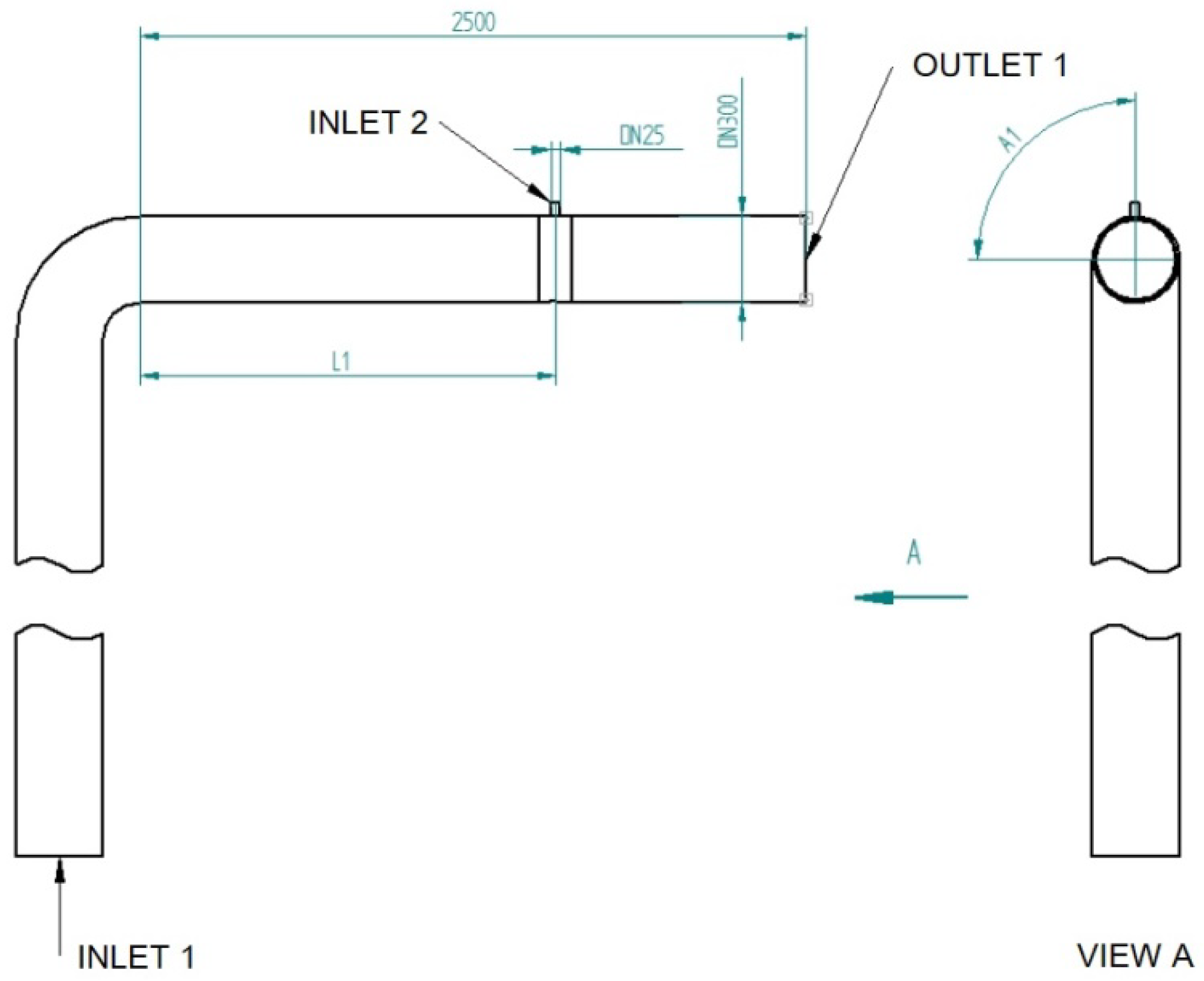
3] presented a method of improving combustion dynamics in boilers that operate in power plants, combined heat and power plants, and heating plants. Thanks to the proposed method, a greater degree of fuel burnout is obtained, which, in turn, results in lower energy consumption for the production of the same amount of power. The parameters of the emitted exhaust gases and ash are also improved. The method described in the article involves the adding of a catalyst to the dust duct of a boiler (
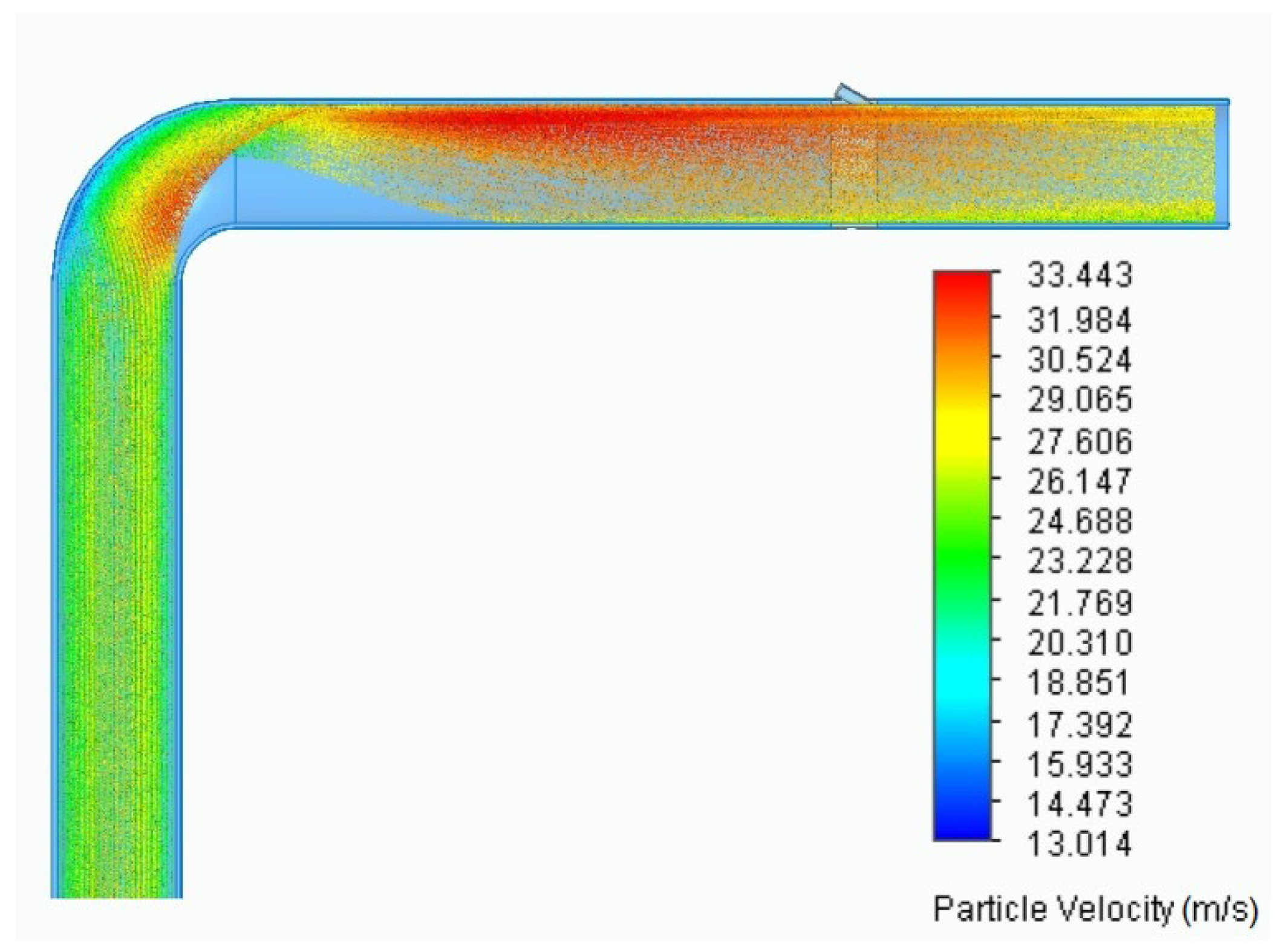
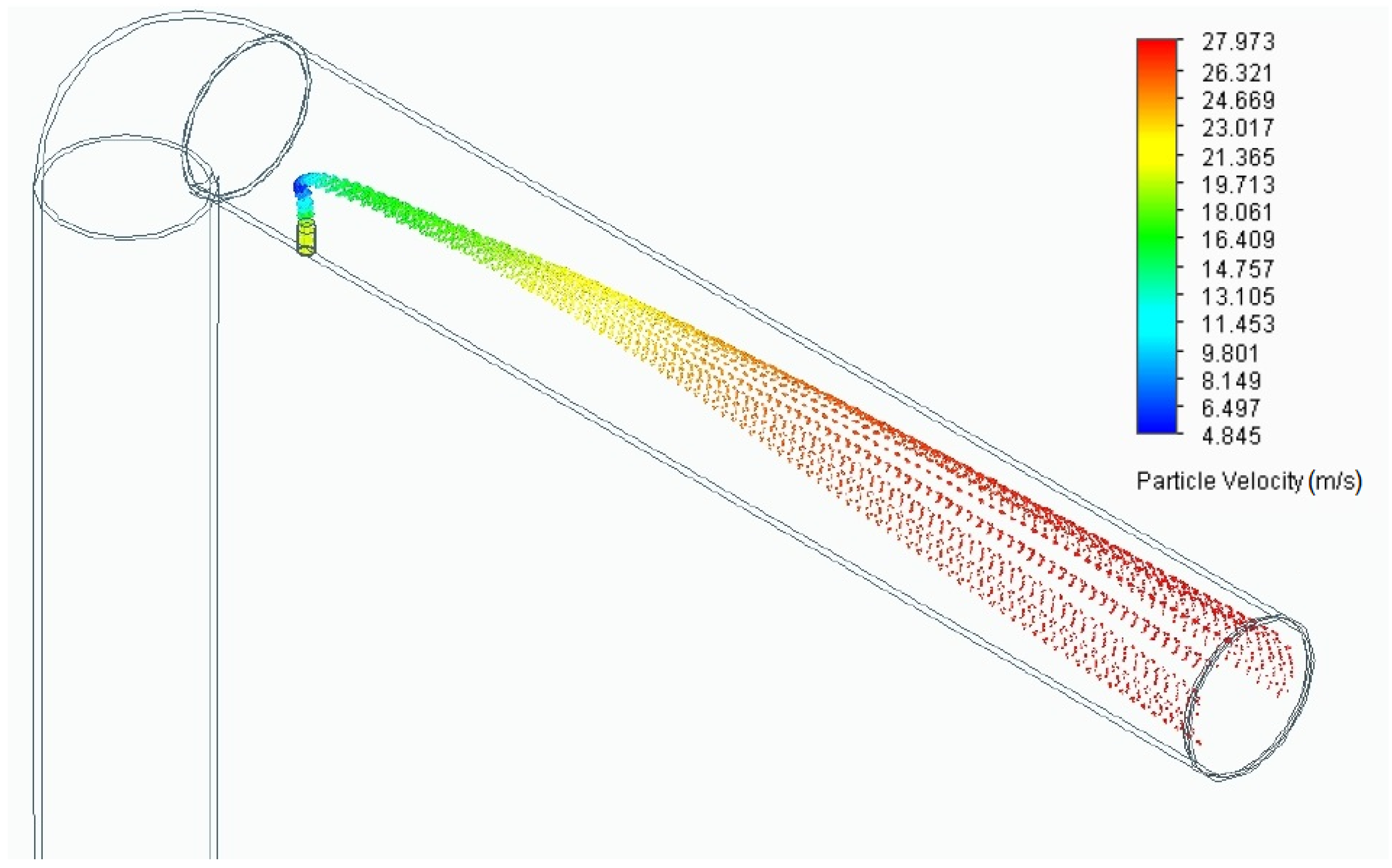
Figure 1), which improves the combustion parameters. The catalyst is applied with the use of a sprayer/nebulizer. In order to obtain the correct flow parameters, this nebulizer was modeled using CFD calculations. The calculations included the trajectories, velocities, concentrations, and pressure distributions for various flow parameters. The results of these measurements allow for the assessment of the parameters that guarantee the delivery of the catalyst (in the desired form) to the outlet of the dust duct (
Figure 2). The method described in this article involves the intensification of the combustion of solid fuels in a boiler with the use of alkyl alcohol and the Al-Ni catalyst as combustion promoters. It should be noted that the catalyst only works if there is alcohol in the droplets. In the event of evaporation, the desired effect will not occur. Thanks to the use of this method, a greater degree of fuel burnout is obtained, which, in turn, results in both lower energy consumption for the production of the same amount of power and an increased stability of the flame. The parameters of the emitted exhaust gases and ash are also improved.
Overall, the dust ducts are an important component of the coal handling system in pulverized coal-fired boilers, and they play a critical role in ensuring the reliable and efficient operation of these systems. Continued research and development in this area could lead to the development of more advanced and effective dust ducts that are able to improve the performance and reliability of pulverized coal-fired boilers. In the laboratory, research on dust ducts can help to better understand the fundamental principles of pneumatic conveying and the factors that influence the performance of these systems. This type of research can be used to develop new designs and technologies for dust ducts, as well as to identify and solve problems that may arise in their operation. In the industrial scale, research on dust ducts is equally important as it can help to improve the performance and reliability of these systems in real-world applications. This can include the development of new materials and manufacturing processes that are better suited to the demanding conditions of the coal handling system in a pulverized coal-fired boiler, as well as the development of advanced control and monitoring systems that can optimize the performance of the dust ducts. Overall, research on dust ducts is important in both the laboratory and industrial scales as it can help to improve the efficiency and reliability of these systems and ultimately contribute to the overall performance and environmental impact of pulverized coal-fired boilers.
2.2. New Combustion Catalysts
Increasing production efficiency is a very important issue in the energy sector because it is associated with fuel savings, as well as with reducing the amount of pollutants emitted per unit of generated energy. One possibility of increasing the energy efficiency of boilers is the use of modifiers (catalysts) that can be added to fuels [
8]. They improve the effectiveness, efficiency, and speed of the combustion process, e.g., by burning heavier hydrocarbon fractions that are formed during fuel combustion and thus by reducing the loss of incomplete combustion. At the same time, this affects the level of pollutant emissions into the atmosphere [
9]. The used catalyst is expected to have high catalytic activity and also high mechanical strength and abrasion resistance (so that it is not subjected to mechanical damage). A spherical shape; monodispersity, with regard to particle distribution; and also a nanometric size are preferred. In addition, the catalytic stability of the catalyst is important [
10]. The aspect that needs to be optimized is the appropriate amount of added catalyst. There are many limitations related to the selection of additives, e.g., the common problem of the high price of catalytic materials, as well as the fact that some of them cause corrosion or contaminate combustion products [
8].
Based on the literature review, it can be concluded that the topic of selecting the type of catalyst for the coal combustion process, as well as its optimization and modification, is a very popular issue [
11]. There are several types of catalysts that can be used in boilers, each with its own advantages and disadvantages. One type of catalyst that is commonly used in boilers is a metal oxide catalyst, which is made from a combination of metal oxides and other materials. Metal oxide catalysts are effective at increasing the efficiency of burning fuels, and they are relatively inexpensive to produce. However, they can be sensitive to temperature and may need to be replaced periodically. Another type of catalyst that is commonly used in boilers is a zeolite catalyst, which is made from a porous, crystalline material called zeolite. Zeolite catalysts are highly effective at increasing the efficiency of burning fuels, and they are relatively stable and long lasting. However, they can be more expensive to produce than metal oxide catalysts. A third type of catalyst that is sometimes used in boilers is a hydrocarbon catalyst, which is made from a mixture of hydrocarbons and other materials. Hydrocarbon catalysts are effective at increasing the efficiency of burning fuels, and they are relatively stable and long lasting. However, they can be more expensive to produce than metal oxide catalysts, and they may produce more pollutants when burned. In terms of a comparative analysis, it is important to consider the specific needs and goals of a particular boiler system when choosing a catalyst. Metal oxide catalysts may be a good choice for systems that are looking for an affordable, effective solution, while zeolite catalysts may be a better choice for systems that are looking for a more durable, long-lasting solution. Hydrocarbon catalysts may be a good choice for systems that are looking for an effective solution with relatively low pollutants, but they may be more expensive and may require more frequent replacement. Ultimately, the best catalyst for a particular boiler system will depend on a variety of factors, including the specific fuel being used, the efficiency goals of the system, and the available budget.
The most commonly used catalysts include copper compounds and sodium chloride [
12]. The amount of introduced catalyst depends on the surface area of the furnace. In 1997, a method of producing a specific catalyst, which allows for the optimization of the coal combustion process, was patented by Chinese scientists. The first step of this method involved the preparation of a suitable HN or CaN carrier. For this purpose, natural zeolite was soaked in a solution of HCl or CaCl
2. Afterwards, the carrier was placed in a machine in order to be blended. It was mixed with a saturated solution of FeSO
4, Cu(NO
3)
2, and H
2GeO
3 in specific proportions at an appropriate temperature (60-120 °C) and at properly selected time intervals. The mixture was then roasted for 4-8 h at 500-700 °C. The catalyst produced by this method has high activity and enables the efficiency of coal combustion to be increased, while, at the same time, enabling the quantity of the slag and the amount of discharged harmful gas to be reduced [
13].
Marcewicz-Kuba and Olszewska [
14] present the results of research concerning the impact of modifying DESONOX-type catalysts on the reduction in sulfur dioxide emissions generated during the hard coal combustion process. DESONOX-type catalysts are a very interesting alternative for flue gas desulfurization. They consist of a carrier, which is a zeolite or montmorillonite, and an active material, which can be transition metal ions. The authors of the research focused primarily on the impact of the catalyst’s preparation, with particular emphasis on the method of impregnating the active material on the carrier in relation to the obtained catalytic activity. Catalysts containing nickel and cobalt ions that are applied using one of three methods were compared. These methods include impregnation, adsorption of appropriate nitrates from aqueous solutions, and the use of modified methods: adsorption of appropriate nitrates from a water–sucrose solution and double impregnation using EDTA solution. The addition of the catalyst significantly reduced the emission of sulfur dioxide. In the case of using cobalt ions, the maximum degree of SO
2 reduction in flue gases was 60%, while in the case of nickel it even reached 85%.
Wang et al. [
15] studied the process of co-incineration of sewage sludge (SS) and coal dust (PC). In addition to the analysis of various variants that result from the variable quantitative shares of individual substrates, the influence of the catalyst on the course and characteristics of combustion was also examined. The tested catalysts were CaO, CeO
2, MnO
2, and Fe
2O
3. The obtained results showed that all the tested catalysts improved the combustion activity of the fuel mixture and also caused an increase in the combustion rate of solid coal. As a result, the ignition temperature and burnout temperature of the fuels were lowered. Considering full combustion efficiency and activation energy as the evaluation criteria, the best catalytic effects were obtained for CeO
2. In turn, Fe
2O
3 can be considered to be the second best of the tested catalysts. However, due to economic aspects, it seems more sensible to use Fe
2O
3.
Fedorov et al. [
10] present a method of obtaining an innovative CuFeAl nanocomposite catalyst, which can be successfully used in the combustion processes of, e.g., lignite. It was shown that the developed spherical CuFeAl nanocomposite catalyst exhibits high CO oxidation activity, is characterized by satisfactory mechanical properties, and has a high stability temperature (up to 800 °C).
Hu et al. [
16] determined the effect of selected catalysts on the characteristics and kinetics of the combustion of coal–char blends when using thermogravimetric analysis (TGA) and differential scanning calorimetry (DSC). Catalysts, such as Fe
2O
3, CaO, and MnO
2, were analyzed. The obtained test results showed that all the tested catalysts had a positive effect on the combustion characteristics of coal–char blends (especially in the initial period of the process). The addition of a catalyst in the amount of 1.5% by mass can satisfactorily improve the emission of volatile substances and also lower the ignition temperature. The new catalysts optimize the coal combustion process and are widely applicable to various types of coal (e.g., lignite, peat, soft coal) [
17]. Their great advantage is their simple production process, with the possibility of easily extending the scale of laboratory production to mass production. The developed catalyst may be produced by, e.g., dissolving raw materials in water and by distributing them evenly. The raw materials contain the following components by weight: 0.05–1% of an iodine compound, 0.5–5% of a rare earth compound, 0–15% of alkali metal salts, and 0–20% of earth metal salts [
17].
In order to develop effective catalysts for use in pulverized coal-fired boilers, researchers would need to consider a number of factors, including the chemical composition of the coal being burned and the specific pollutants that are being targeted. They would also need to consider the operating conditions of the boiler, including temperature, pressure, and the presence of other substances, which could affect the performance of the catalyst. Overall, the development of advanced catalysts for combustion in pulverized coal-fired boilers is an area of research that holds significant potential for improving the performance and environmental impact of these systems. Further research in this area could lead to the development of new and more effective catalysts that could be widely adopted in the power generation industry.
2.3. Supplying a Catalyst to a Dust Duct
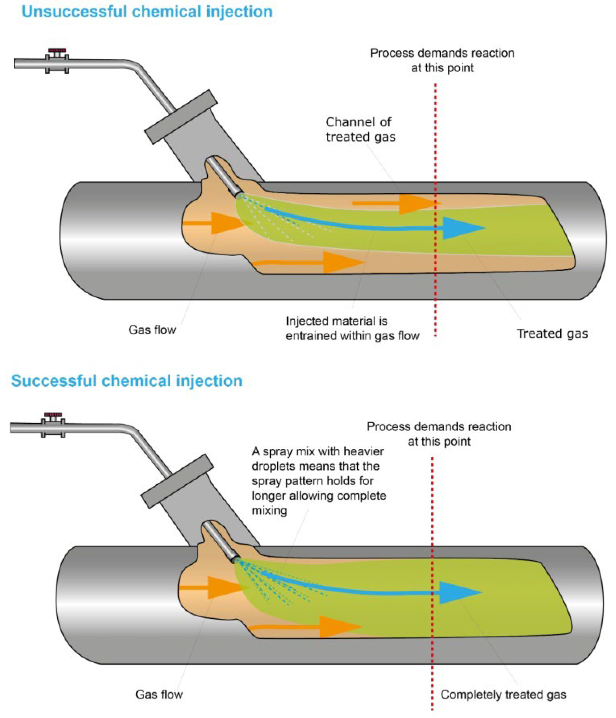
Another alternative solution to optimizing and improving the efficiency of the combustion process in boilers, which is used in many industries, is the method of delivering a catalyst to the system. The key role in this matter is played not only by the type and form of the catalyst, and the place of its injection but also by the injection system itself. Liquid that is injected into different fluid or gas mixes naturally over time (
Figure 3). The speed of this mixing depends on how evenly the liquid was distributed—the finer the spray, the quicker the mixing. In a moving fluid stream, the complete mixing of, e.g., fluid with the catalyst, may be required. This limits the time, ways, and possible locations of injecting the fluid that must be fully distributed. Quick and efficient mixing can be provided by selecting an effective nozzle. It is the angle of the spray stream or the consistency of the sprayed liquid that require adjustment. Finer sprays can often achieve the required mixing. When only small amounts of an additive have to be delivered into the system, the flow rates will need to be maintained at a low level. In such cases, a finely atomized spray is necessary. However, it is worth noting that fine atomization requires high pressure and high flow rates [
18].
All of the above-mentioned factors have a direct impact on the properties of the generated spray (droplet size and distribution spectrum). In the subject literature, numerous pieces of work that are devoted to various atomizers can be found. The most commonly used atomizers in combustion processes are: pressure, swirl, and pressure-swirl atomizers. Currently, effervescent-swirl atomizers are also becoming more and more popular [
19].
Bielecki et al. [
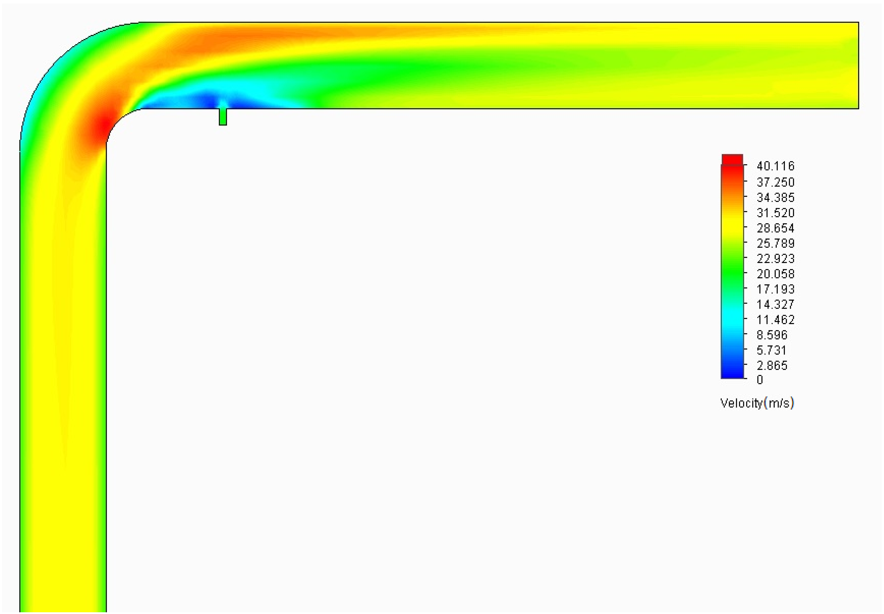
20] describe the possibility of feeding a catalyst using a jet atomizer. This solution is an innovative and interesting approach. The conducted tests showed that in this case a desired droplet size is 30 µm at a distance of 1 m from the nozzle’s outlet. As the distance increases, the desired droplet size should also increase in order to achieve the best efficiency of the process (
Figure 4). Current research shows that the best place for dosing the catalyst is probably to feed it behind the elbow pipe at a specific angle (
Figure 5) [
21]. However, it is worth noting that during the two-phase atomization, it is not only the catalyst but also air that is supplied to the system. Future research should focus on trying to reduce the amount of air supplied to the system, which is of particular importance during laboratory-scale tests. On an industrial scale, the introduction of excess air in an amount of < 1% should not be a significant problem. In connection with the above, it is worth attempting to modify the atomizer in order to reduce the amount of air that is supplied to the system together with the catalyst. One possible solution is the use of effervescent atomizers. It is also possible to try to reduce the amount of air supplied to the atomizer itself, thanks to which the amount of air supplied to the boiler will be limited.
Najafi et al. [
22] describe the micro- and macroscopic characteristics of atomization that was carried out using a pressure-swirl atomizer injecting heavy fuel oil. The conducted research proved that the heavy fuel oil (HFO) atomization method is very important when determining the efficiency of gas generators. The atomizer proposed in the paper proved to be effective in the spraying process that was carried out under various operating conditions (pressure and temperature). The use of pressure-swirl atomizers in the combustion process is also described in [
23,
24].
Effervescent atomization is a technique that can be used in pulverized coal-fired boilers to improve the efficiency and environmental performance of the combustion process. It involves the use of a special nozzle that generates a fine mist of pulverized coal particles and mixes them with air and steam. The mist is then injected into the boiler, where it is burned to produce heat and generate electricity. The use of effervescent atomization can improve the efficiency of the combustion process by ensuring that the coal is more evenly distributed and fully mixed with the air and steam, which can lead to more complete and efficient combustion. There are several potential benefits to using effervescent atomization in pulverized coal-fired boilers. For example, it can help to reduce the formation of pollutants, such as carbon monoxide and particulate matter, which can have negative impacts on air quality and public health. It can also help to reduce the amount of unburned coal particles that are released into the environment, which can be a major source of pollution. The use of an effervescent atomizer in the combustion chamber of a gas turbine, internal combustion engine, furnace or boiler, and also in other areas was discussed in papers [
25,
26]. An effervescent atomizer is a type of atomizer that uses bubbles as the atomizing force and which conducts the atomization process by creating bubbles, and then mixing, deforming, and blowing them out through the outlet. When compared to conventional pressure and pneumatic atomizers, effervescent atomizers are highly efficient, economical, and environmentally friendly. Therefore, they are attracting more and more interest from various environments. This type of atomizer is also popular due to the possibility of atomizing very viscous liquids (such as liquid fuels) into a fine spray at a low gas consumption [
27,
28]. In the study in [
29], the characteristics of the flow and the analysis of the energy balance of effervescent spraying were performed. The work includes a theoretical and experimental approach. The studies showed the influence of the gas–liquid velocity on the stability of atomization. When the GLR was small, the atomization was unstable. The atomization was gradually becoming more stable as the GLR increased. The optimum atomization area can then be obtained. The Sauter mean diameter (SMD) of the droplets was measured with a phase Doppler analyzer, and it was shown that the SMD decreases with an increasing GLR. Paper [
30] describes an innovative application of an effervescent atomizer, which is a new technology for atomizing cells in order to reduce the gas-to-liquid ratio. The paper proposes an atomizer of the authors’ own design. The conducted tests confirmed that the use of the new atomizer is suitable for cellular applications that require reduced amounts of supplied air. The effective use of effervescent atomizers in medicine is also described in [
31]. This approach may be an inspiration to expand the use of the effervescent atomizer. Effervescent atomizers are also subjected to various modifications in order to increase the efficiency of the spraying process and to adjust the properties of the generated aerosol to the requirements of a given process. Ochowiak et al. [
32] present an effervescent atomizer equipped with an air stone aerator. The use of additional aeration in the atomizer by means of an aerator contributed to the reduction in the average diameters of the generated aerosol. The obtained data are interesting from the point of view of designing new atomizers, in particular, two-phase atomizers. Niland et al. [
33] also undertook a study on an effervescent atomizer equipped with an aerator. In this experimental work, an internal flow field in the atomizer was presented for the first time, and an attempt was made to explain the complex mechanisms of the effervescent atomization process. The influence of working parameters (such as the air-to-liquid flow rate ratio (ALR), working pressure, the diameter of the aerator opening, aeration area, and the diameter of the mixing chamber) on the internal flow in the effervescent atomizer were investigated. When the ALR value increases, the gas injection mechanism takes the following forms: single bubbling, pulsed bubbling, elongated jetting, atomized jetting, and evacuated chamber. In addition, the flow regime changed with an increase in the ALR—from bubble flow to screw flow, then to swirl flow, and finally to annular flow. The dense-bubbly and bubbly slug flow regimes were also observed to produce stable aerosols with droplet sizes ranging from 50 to 80 μm for an ALR of 0.25%-1.50%. An example of the trajectory of the droplets with diameters of 50 micrometers, which were injected into the dust duct, is shown in
Figure 6 [
21]. In order to effectively implement effervescent atomization in pulverized coal-fired boilers, it is important to carefully design and optimize the nozzle and other components of the system. This can involve the use of advanced computational modeling and simulation techniques to optimize the design and operating conditions of the system. Overall, effervescent atomization is a promising technology for improving the efficiency and environmental performance of pulverized coal-fired boilers. Further research and development in this area could lead to the widespread adoption of this technology in the power generation industry.
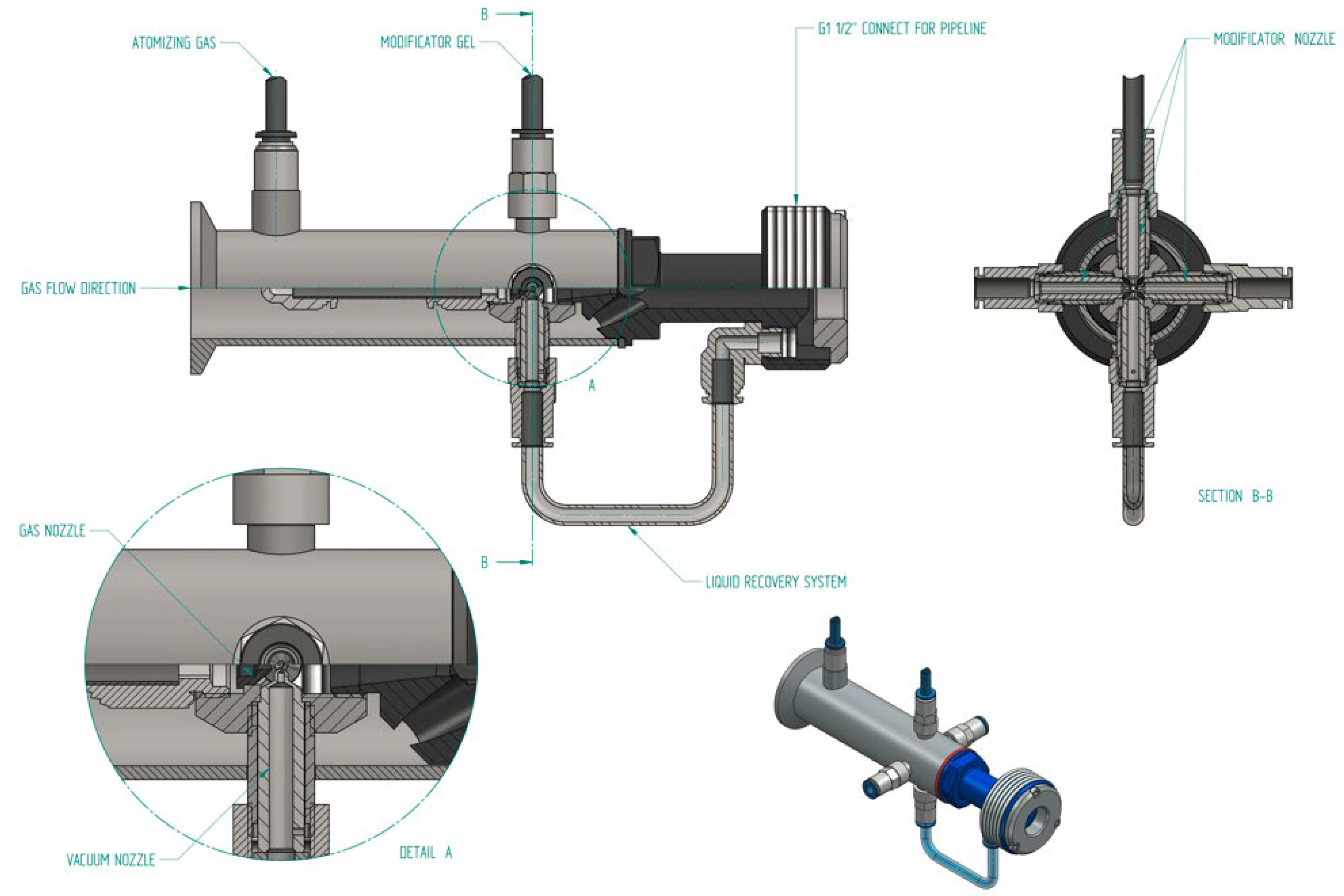
More and more advanced atomizer designs, i.e., multi-phase reactors, are used to generate droplets. The commonly used designs of reactor mixers with liquid spraying are limited either by the size of the generated droplets or the maximum viscosity of the sprayed substance, as well as the intensity of its stream. In order for the reactor (
Figure 7), which is described in paper [
34], to generate droplets of the assumed average diameter and velocity, the pneumatic atomization of the substances fed through internal nozzles that have a diameter selected appropriately for the sprayed substance should be used. The outlets of these nozzles must be placed on the axis of the gas nozzle’s outlet. The diameter of the gas nozzle is selected with regard to the assumed droplet diameter and the speed value required to atomize the substance. When developing new designs, it should be remembered that droplets with appropriate diameters and a specific atomization spectrum need to be generated. Moreover, there should be a small amount of additional air, and the construction of the atomization device should be as simple as possible. At the actual gas flow velocity of 20 m/s, the minimum droplet lifetime is 0.05 s. Assuming that the droplets have a diameter of about 30 µm, the resulting droplet evaporation time is about 1.4 s for a temperature of 293 K, 0.1 s for a temperature of 308 K, 0.087 s for a temperature of 313 K, and 0.023 s for a temperature of 373 K. Therefore, such a droplet would be able to cover the required distance in the aerosol while taking into account the changes in the temperature along the length of the dust duct, leading to the boiler [
3,
35]. For practical reasons (this is the average diameter, and, therefore, a significant number of droplets may have smaller diameters), it is better to generate a droplet with a larger diameter, e.g., 50 μm. This is due to the fact that flow conditions and the length of a dust duct may not only affect the diameters of the generated droplets but also the droplet’s lifetime. During this time, smaller droplets evaporate and/or coalesce to form larger droplets, and they also undergo other transformations [
3,
20,
35].
2.4. Control, Automation, Neural Networks, and Flame Imaging Methods
One of the possible and justified methods of development is automation through the use of electronics dedicated to the process and the use of the best quality fuels (including the aforementioned improved quality coal), which may result in the cleanest and most effective combustion. The automatic control of a boiler’s operation is one of the ways to increase its combustion efficiency and to reduce the amount of toxic compounds emitted to the environment [
36]. In paper [
37], a fuzzy logic control algorithm was used to control the amount of air that is needed for fuel combustion. The amount of air, before entering the combustion chamber, was regulated. For this purpose, the relationship between the actual amount of air required for combustion in the boiler and the amount of oxygen contained in the flue gases was used. Thanks to the use of the control system, the efficiency of the boiler increased by 4.34%. However, it was shown that the efficiency of the control process was influenced by the heat of combustion and the moisture content of the fuel.
In the combustion process, the important parameters for identifying instabilities are the flame’s temperature in the combustion chamber and the rate of heat release. Zhong et al. [
38] describe a sensor, the indications of which depend on radical emission spectroscopy. Changes in the heat release rate can be determined from the spectral intensities of a single band, whereas the flame temperature can be calculated from the ratio of the spectral intensities of the two bands.
Another solution for controlling the combustion process can be a predictive controller that allows for the controlling of the timing of fuel injection and ignition. The advantage of a predictive control system is its ability to take into account the limitations that are imposed on the controlled and controlling quantities during the design of a controller. It is one of the most effective methods for controlling non-linear systems in the case of state and control limitations. Ahmed et al. [
39] presented a model predictive controller for controlling the timing of both injection and ignition. The proposed controller is an auxiliary heating element for controlling combustion phases with self-ignition on a cycle-to-cycle basis. Simulation results obtained using a virtual non-linear engine show that the integral formula of the speed-based predictive controller enables the combustion phases to be tracked and the ignition to be controlled. In addition, the model allows for the coordination of two actuators over the entire range of the operating conditions of the combustion process, without the need to re-tune the controller.
Moreno et al. [
40] analyzed how the design of a controller affects combustion efficiency in a standard diesel engine with preliminary and main injection. Two types of controllers were tested during the conducted research. The first controller operated in a cycle and optimized injection continuously in order to achieve the highest combustion efficiency. The greatest advantage of controlling combustion in a cycle is the more accurate regulation of combustion. This solution was used to minimize random changes during the combustion process. The mass of the burnt fuel (from pre-injection) has the greatest influence on the combustion process. The second controller worked in an indirect way. The maximum pressure, the maximum velocity of an increase in pressure, and also the maximum and minimum flue gas temperatures were analyzed.
A common approach to controlling the indicated mean effective pressure (IMEP) outlet for a diesel engine is to use a calibrated map to control open-loop combustion. However, due to changes in the operating environment of the engine, combustion control may be inaccurate. An additional problem is the difference in the combustion process between the cylinders, which differ in terms of their construction and operation. This difference cannot be compensated for in an open loop. As a result, this leads to a deterioration in the efficiency of the combustion process and an increase in exhaust gas emissions. The solution to this problem may be the use of closed-loop combustion control (CLCC). Study [
41] proposed a reference governor-based combustion control (RGCC) strategy for balancing the indicated mean effective pressure, the reference and variable feedback values of which were generated based on a modified Kalman filter (KF) algorithm instead of on an MAP. Its effectiveness and efficiency were compared with the results of experimental studies on a commercial diesel engine test rig, which were carried out under steady-state and transient conditions [
41].
The use of artificial neural networks, which have access to very large data sets, is another direction of development in the field of process control. Artificial neural networks are used in the case of large coal-fired boilers, e.g., for predicting emissions of toxic combustion products [
36]. Krzywanski et al. [
42] used an artificial neural network (ANN) to estimate SO
2 emissions from circulating fluidized bed (CFB) boilers. It was proven that ANNs can be used to determine the amounts of SO
2 coming from small and large CFB boilers for a wide range of operating conditions, i.e., in air-firing, oxygen-enriched, and oxycombustion conditions.
In paper [
43], a model of a combined supercritical CO
2 (sCO
2) Brayton cycle–organic Rankine cycle (ORC) was proposed in order to increase the efficiency of the supercritical CO
2 (sCO
2) Brayton cycle. The model took into account specific designs of sCO
2 boilers, recuperators, coolers, and turbomachines. Artificial neural networks were also used to determine pressure drops and, as a result, to simplify the designed model. The proposed model enables the time of the processor to be reduced by more than 50%. Moreover, it also results in an increased thermal efficiency by 2.75% when compared to the supercritical CO
2 (sCO
2) Brayton cycle operating alone.
Han et al. [
44] proposed a hybrid deep neural network model in order to determine the amount of NOx in exhaust gases. An adversarial denoising auto-encoder (ADAE) model was used to determine the flame’s characteristics, whereas least support vector regression (LSSVR) was used to identify the amount of NOx. The correctness of the AD-AE-LSSVR model was verified on the basis of flame images of a 4.2 MW heavy-oil-fired boiler. In turn, the hyperparameters of the model were optimized in order to achieve greater process efficiency. The ADAE-LSSVR model allowed for the achievement of the high efficiency of the process and satisfactory accuracy of the prediction of the amount of NOx. The correlation coefficient R
2 was equal to 0.97. The proposed model has better features when compared to other models, e.g., artificial neural networks (ANN), extreme learning machine (ELM), and support vector regression (SVR).
One way to characterize the combustion process is to use the radiation emitted by the flame. The most important parameters of the combustion process can be determined from the recording of the flame’s image. Based on the observation of the flame, it is possible to determine the content of CO, CO
2, H
2O, H, NOx, or O
2, as well as the pressure, temperature, amount of heat released, air–fuel ratio, and many other quantities. It is extremely important to observe the flame zones in order to identify those that are most sensitive to the input parameters of the burner. Within the visible light range, images of the flame are obtained using cameras equipped with silicon image converters. The imaging element allows the radiation to reach the video transducer, where an image (continuous distribution of irradiation) is formed. Afterwards, this image is subjected to the operation of spatial sampling in an image converter, which consists of pixels. Two groups of methods are used to analyze the combustion process based on the shape of the flame: methods that use the contour and methods that use the area. Observing a flame during complex energy processes is a very difficult task. Kotyra [
45] presents a multi-channel, fiber-optic flame monitoring system in industrial conditions. The usefulness of detecting an abnormal state of the combustion process (unstable combustion) and the possibility of using the shape of the flame as a diagnostic signal were analyzed. The obtained results depend on the relative position of the camera and the tested flame. Flame image analysis can be successfully used to control the combustion process.
One of the main causes of damage to the elements of coal-fired boilers installations, leading to breakdowns and, consequently, a shutdown of the block, are erosive processes. The problem of erosion of the dust ducts supplying the pulverized coal–air mixture to the burners was presented by Hernik [
46]. In order to perform calculations, numerical modeling (CFD) in the commercial program Ansys Fluent (Ansys Fluent, Computational Fluid Dynamics, Ansys Inc., Pittsburgh, PA, USA) was used. The identification of places where erosion is expected can be used to protect these places from erosion adequately. It was shown that coal dust particles with a diameter greater than 100 µm largely erode the dust duct’s wall. The author presented a model for the calculation of the erosion process to be used in the dust ducts of the power plant.
