Article

Porous-Structured Three-Dimensional Iron Phosphides Nanosheets for Enhanced Oxygen Evolution Reaction

by
Sundaramoorthy Marimuthu
,
Ayyavu Shankar
and
Govindhan Maduraiveeran
*
Materials Electrochemistry Laboratory, Department of Chemistry, SRM Institute of Science and Technology, Kattankulathur 603 203, Tamil Nadu, India
*
Author to whom correspondence should be addressed.
Energies 2023, 16(3), 1124; https://doi.org/10.3390/en16031124
Submission received: 30 December 2022 / Revised: 13 January 2023 / Accepted: 18 January 2023 / Published: 19 January 2023
(This article belongs to the Special Issue Review Papers in Energy Storage and Related Applications)

Abstract

:
A rational designing nanostructured Earth-abundant and non-precious electrocatalysts for promoting an anodic oxygen evolution reaction (OER) is crucial for cutting-edge energy conversion and storage fields. Herein, we demonstrate a porous structured three-dimensional (3-D) FeP nanosheets on NiO modified Ni electrode (PS-3D-FeP@NiO|Ni) using of a facile and two-step electrodeposition strategy that exhibits enhanced OER under alkaline electrolyte. The as-developed porous-structured 3-D FeP nanosheets on NiO modified Ni electrode exhibits the best OER catalytic activity in relations of low onset potential (ղonset) of ~1.37 V (vs. RHE), small overpotential (η) of ~0.17 V to produce the current densities of 10 mA cm−2, lower Tafel slope value of ~40.0 mV/dec, higher turn-over frequency (TOF) of 0.435 s−1, and long-term stability when compared to other CoP@NiOǀNi, NiP@NiOǀNi, CuP@NiOǀNi, NiP|NF (nickel foam), and commercial IrO2|Ni electrodes established in this study. The anodic current density is calculated at the potential of ~1.80 V to be ~580, ~365, ~145, ~185, ~516, and 310 mA cm−2 for PS-3D-FeP@NiO|Ni, CoP@NiOǀNi, NiP@NiOǀNi, CuP@NiOǀNi, IrO2|Ni, and FeP|NF electrodes, respectively. The porous structured 3-D FeP nanosheets on NiO modified Ni electrode demonstrated a highest current density of ~580 mA cm−2 at ~1.80 V in comparison to other electrodes employed in the current investigation. The outperforming OER activity of PS-3D-FeP@NiO|Ni is majorly associated to its porous-structured 3-D sheet-like morphology, large amount of electrochemical active surface area, high electrical conductance characteristics and self-activated/supported active sites, facilitating the catalytic properties. The surface morphology, crystalline structure, chemical composition, and distribution of Fe, P and O elements have not been altered significantly after had a long-term OER test. These experimental results reveal that further optimization of porous structured 3D FeP nanomaterials is highly anticipated for practical water electrolysis systems.

1. Introduction

Growing concerns with the energy problem and environmental pollution have prompted researchers to look into alternative energy sources to traditional energy sources [1,2]. Water electrolysis is considered as an emergent electrochemical technology for converting energy to generate a non-toxic and sustainable chemical fuel of hydrogen (H2) [3,4,5]. Electrochemical water electrolysis is a highly demanding reaction, and ground-breaking advances are highly necessary to greatly improve the overall efficiency through rational design and advancement of catalysts for hydrogen evolution reaction (HER) and oxygen evolution reaction (OER) [6,7]. Particularly, the electrochemical water oxidation is a critical for electrochemical energy conversion and storage applications [8,9].
As a result, considerable efforts have been made over the last several decades to design an emergent OER catalyst that will facilitate electrode kinetics and its stability in acidic as well as alkaline medium. Typically, the low availability in earth-crust and higher price of the state-of-the-art materials like Pt, IrO2, and RuO2 limit its practicability [10,11,12]. Non-noble metal based catalytic materials such as transition metal phosphides [13,14], sulfides [15,16], hydroxides [17,18], and non-metallic catalysts, are currently being investigated for improving OER [19,20]. The NiO-based catalysts have been employed for various electrochemical energy conversion reactions with low overpotential and high catalytic current densities [21,22,23]. Recently, Bu and co-workers reviewed the recent progress of nickel–iron-based electrocatalysts such as layered hydroxides, metal-organic frameworks, oxyhydroxides, alloys, etc., for improved OER under alkaline electrolytes [24]. Transition metal phosphides (TMP) newly sparked a lot of interest in electrocatalytic OER due to the fact of their low electrical resistivity, high catalytic activity, and ever-lasting stability [25,26]. TMPs have been prepared using a variety of processes, including the solvothermal approach [27], solid-state reduction [28], gas–solid reaction [29], and electrodeposition [30].
For instance, Liu et al. recently reported the fabrication of a FeP coated CeO2 electrocatalyst (FeP@CeO2) by using electrochemical deposition and high-temperature phosphorylation in which the electrode materials delivered the OER overpotential of ~0.24 V at a current density of 100.0 mA cm−2 and a Tafel slope of ~39.1 mV dec−1 [31]. Huang and co-workers prepared a Ni0.75Fe0.25-P/PO3@f-CNT catalyst through a two-stage method using a liquid-phase decoration and gaseous phosphorization approach that exhibited OER overpotential of ~0.23 V at 10 mA cm−2 and Tafel slope of ~45.5 mV dec−1. It is reported that Fe oxide motifs at the edge, corner, or defect locations of Fe oxy-hydroxide, exhibit electrophilicity to mediate the water oxidation reaction. Furthermore, recent studies have discovered that transition-metal phosphide have stronger OER activity than other phosphides [32]. However, TMP derived electrocatalysts still present relatively lower OER catalytic performance when compared to state-of-the-art electrocatalysts.
Therefore, considerable efforts to enhance the inherent OER catalytic activity improve the conductivity and optimize the mass-transport characteristics may be executed [33]. Due to the adaptability and extreme prominence, the electrodeposition of TMP has extended devotion on spanning the central nanoscale materials to practical systems and capability to control the structure and electrochemical characteristic relations via amendment of electrochemical parameters [34]. On the other hand, it is worth emphasizing that the choice of electrode substrate is an important aspect in increasing OER performance and gaining fresh insights for handling industrial-scale challenges. As a result, the design and development of inexpensive, exceedingly active, and simple-to-fabricate OER electrode for water electrolysis is a key challenge.
Herein, we report a cost-effective and highly active OER catalyst that fabricates using a facile two-step strategy of porous-structured three-dimensional (3-D) FeP nanosheets on NiO modified Ni electrode (PS-3D-FeP@NiO|Ni) for the first time. The resultant PS-3D-FeP@NiO|Ni electrode delivered outperforming electrocatalytic OER activity under alkaline electrolyte. Specifically, the PS-3D-FeP@NiO|Ni electrode exhibited low onset potential (~1.37 V (vs. RHE)), small overpotential (η) (~0.17 V @ 10.0 mA cm−2), small Tafel slope (~40.0 mV dec−1), high turn-over frequency (TOF) (0.435 s−1), and long-term stability in comparison with the other electrodes examined in the present study and commercial IrO2|Ni electrodes.

2. Experimental Section

2.1. Materials

Cobalt (II) nitrate hexahydrate (Co (NO3)2.6H2O), ferric chloride anhydrous (FeCl3), copper sulphate (CuSO4), and nickel (II) nitrate hexahydrate (Ni (NO3)2.6H2O) were received from Sigma-Aldrich. Nitric acid (HNO3) and sodium dihydrogen phosphate (NaH2PO4) were received from Alfa-Aesar. The potassium hydroxide (KOH) and commercially available IrO2 catalysts were received from Sigma-Aldrich. All analytical-grade reagents were employed exactly deprived of any additional refinement. All of the solutions in this investigation were made with pure water collected from the ultra-pure deionized water purification system.

2.2. Fabrication of PS-3D-FeP@NiO Nanostructured Electrode

The nickel electrode initially was sonicated for 10 min in a 3.0 M HCl solution to remove any NiOx deposit on the surface, and then completely eroded by water and ethanol before drying in the air. The porous-structured three-dimensional (3-D) FeP nanosheets on NiO modified Ni electrode (PS-3D-FeP@NiO|Ni) was fabricated using a two-step approach. First, nickel electrode was dipped in a 0.1 M nitric acid solution for 1 h to form the rough nickel oxide surface [35,36]. The nickel oxide layer was formed on the surface of Ni electrode via natural formation of the passivation or oxide thin layer when an adequate local concentration was achieved [37]. The formed oxide on nickel surface led a rough surface and created more active oxides, which led to the establishment of a hetero-interface. This may influence the growth of 3D FeP sheets as well as the influence the activity of the catalysts. However, the formed nickel oxide may not dissolve under acidic solution as there is a simultaneous deposition of Fe and P on the surface of NiO|Ni electrode. Second, the resultant NiO modified Ni electrode was dipped in the electrolyte solution containing 0.1 M FeCl3 + 0.075 M sodium dihydrogen phosphate + 0.1 M nitric acid and applied constant potential of 0.9 V (vs. RHE) for 40 min using a potentiostatic approach [38]. In the typical electrodeposition process (Scheme 1), FeCl3 was used as the Fe3+ source, sodium dihydrogen phosphate was employed as the phosphate source, and nitric acid was utilized as the electrolyte. The transition metal cations of Fe3+ and hypophosphite anions in the electrolyte solution were reduced into their corresponding Fe atom forms by constantly applied potentials of 0.9 V (vs. RHE) for 40 min, according to the following Equations (1)–(3):
Fe3+ + 3e → Fe
H2PO2 + 2H+ + e → P + 2H2O
The reduced atoms are generally adsorbed on the electrode surface where P-atoms can diffuse and incorporate into Fe crystal lattices to develop the Fe–P phase.
Fe + P → FeP
The developed PS-3D-FeP@NiO|Ni electrodes were rinsed with water and dried at room temperature for further electrochemical experiments. The mass loading of the PS-3D-FeP@NiO catalysts was measured to be 0.10 mg cm−2.
For the comparison study, all other electrodes, including CoP@NiOǀNi, NiP@NiOǀNi, and CuP@NiOǀNi, were prepared using similar experimental conditions. After formation of NiO on Ni electrode, the resultant electrode was immersed in 0.1 M metal precursors (Co(NO3)2.6H2O or Ni(NO3)2.6H2O or CuSO4) + 0.075 M sodium dihydrogen phosphate in 0.1 M nitric acid and a constant potential of 0.9 V (vs. RHE) was applied for 40 min. The developed TMP@NiO|Ni electrodes were rinsed with water and dried at room temperature for further electrochemical experiments.
The mass loading of the catalysts was computed to be ~0.10, ~0.30, ~0.40, and ~0.20 mg cm−2 for FeP@NiO|Ni, CoP@NiOǀNi, NiP@NiOǀNi, and CuP@NiOǀNi, respectively. To fabricate the commercial IrO2|Ni electrode, typically, the catalyst ink was made by combining ~10.0 mg/mL of commercial IrO2 powder with 1.0 percent Nafion solution. The mixture underwent 30.0 min of ultrasonic treatment to create a uniform dispersion of IrO2 catalysts. About ~10.0 µL catalyst ink dispersion was cast on nickel foam electrode (~0.81 cm2), and it dried at room temperature. For the comparison, the electrochemical deposition of FeP without porous structures was developed based on the reported method [39]. Typically, the pre-cleaned nickel foam electrode that was immersed in the electrolyte solution contains a precursor mixture of 0.075 M monobasic sodium hypophosphite (NaH2PO2) and 0.1 M of FeCl3. Five continuous cyclic voltammograms (CVs) were recorded at the cleaned NF electrode, operating the potential cycle window between ~1.63 V and ~−0.16 V (vs. RHE) at a scan rate of 5 mV s−1. The resulting electrode was designated as the FeP|NF electrode.

2.3. Physicochemical Characterization

High-resolution transmission electron microscopic (HRTEM) study performed using a JEOL 2010F TEM. High-resolution scanning electron microscopic (HR-SEM) measurements and electron dispersive X-ray (EDX) studies were carried out with a Hitachi SU-70. X-ray diffraction (XRD) analysis was held with a Pananalytical Xpert Pro Diffractometer with a Ni filtered monochromatic Cu Kr (1.5406, 2.2 KW Max). The X-ray photoelectron spectroscopic (XPS) measurements were conducted with PHI Versaprobe III.

2.4. Electrochemical Characterization

Every electrochemical experiment was carried out using an electrochemical workstation (ORIGALYS Origoflex (OGF500) electrochem) in a three-electrode arrangement with nickel electrode (geometrical surface area: ~0.81 cm2), which served as the working electrode. Pt-coil was employed as the counter electrode and silver/silver chloride (Ag/AgCl, 3.0 M KCl) was employed as the reference electrode. The present Ag/AgCl reference electrode was standardized and converted to E(RHE) = E(Ag/AgCl) + 0.059 pH + E0, where E0 = 0.197 V at 25 °C.

2.5. Calculation Method

The mass loading m (g cm2) of the catalysts and the measured current density j (A cm2) at different overpotential (mass activity = j/m) were used to calculate the mass activity value (A g−1). The electrochemical active surface area (ECASA) of the developed electrodes was calculated using double-layer capacitance (Cdl) and specific capacitance (CS) of 0.04 mF cm−2, both of which were measured using cyclic voltammetry (CV) at different scan rates, starting from 10 to 125 mV s−1. The prepared PS-3D-FeP@NiO|Ni electrode has a Cdl of 6.31 mF cm−2 and an ECASA of 157.7 cm2, which are higher than the other electrodes [40].
ECASA = Cdl/CS
The turn over frequency (TOF) was calculated using Equations (5) and (6) [41].
na = mmass/M
TOF = JA/4Fnb
where na is the number of moles of the active sites, mmass is the catalyst loading, and M represents the molar mass of catalysts. J describes the current density at overpotential (η) of ~0.17 V in A cm−2, A is the surface area of the nickel substrate (~0.81 cm2), F represents the Faraday constant (96,485 C mol−1), and nb is the number of electrons transferred.

3. Result and Discussion

3.1. Physicochemical Characterization of PS-3D-FeP@NiO Nanostructures

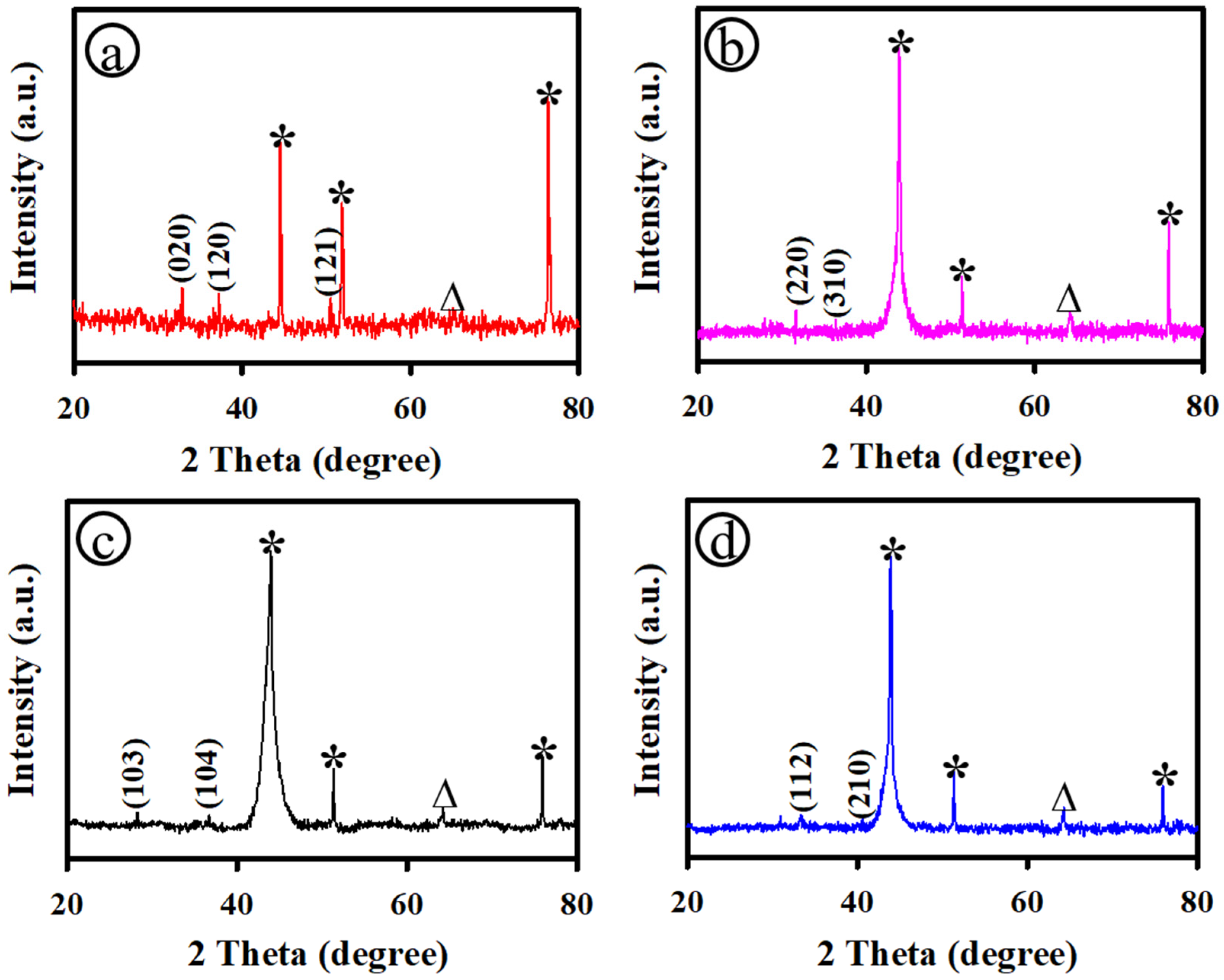
Figure 1 shows the XRD patterns of the PS-3D-FeP@NiO|Ni (a), CoP@NiOǀNi (b), NiP@NiOǀNi (c), and CuP@NiOǀNi (d) electrodes. As depicted in Figure 1a, the porous-structured 3-D FeP nanosheets dispersed on NiO electrode exhibited the peak (angle (2θ)) at ~32.8°, ~37.2°, and ~50.3°, which corresponded to the orthorhombic phase of FeP2 with the crystalline plane of (020), (120), and (121), respectively (JCPDS No. 89-2261) [42]. The CoP@NiOǀNi electrode (Figure 1b) showed the XRD peaks at ~31.6° and ~36.3°, indexed to the cubic phase of CoP3 with the plane of (220), and (310), respectively (JCPDS No. 29-0496) [43]. Figure 1c displays the XRD pattern of NiP@NiOǀNi electrode presented a couple of peaks at an angle (2θ) around ~28.2° and ~36.7°, assigned as the hexagonal phase of Ni5P4 with the planes of (103) and (104), respectively (JCPDS No. 18-0883) [44]. The CuP@NiOǀNi electrode demonstrated the XRD peaks at ~33.4°, and ~40.5°, ascribed to the hexagonal phase of Cu2P with the planes (112) and (210), respectively (JCPDS No. 74-1067) [45]. In Figure 1, the other XRD peaks were marked with a star (*) and triangle (∆) endorsed to the Ni and NiO electrode.
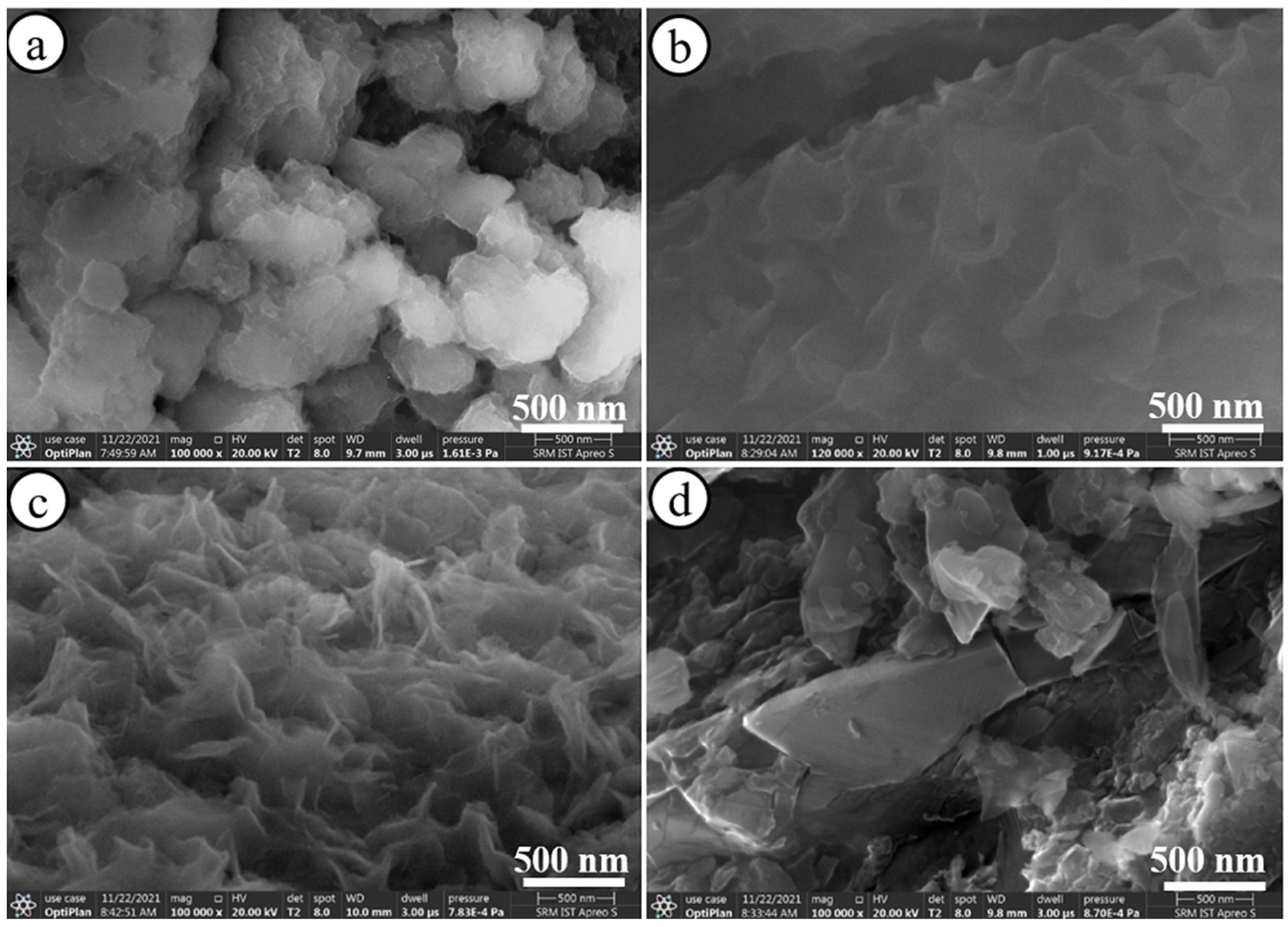
Figure 2 displays the HR-SEM images of the nanostructured PS-3D-FeP@NiO|Ni (a), CoP@NiOǀNi (b), NiP@NiOǀNi (c), and CuP@NiOǀNi (d) electrodes. As displayed in Figure 2a and Figure S1, the PS-3D-FeP@NiO|Ni electrode showed porous-structured three-dimensional (3-D) nanosheet-like FeP dispersed on NiO modified Ni electrode. The average dimension of 3-D FeP sphere was calculated to be ~226.0 nm with a high uniform distribution and the thickness of the FeP nanosheets was estimated to be in the range of ~7.0 nm–~9.0 nm. For our controlled study, the CoP@NiOǀNi, NiP@NiOǀNi, and CuP@NiOǀNi nanostructured electrodes were developed under similar experimental settings. The CoP@NiOǀNi electrode exhibited 2D nanoflake-structured surface morphology with an average thick of ~8.0 nm and is shown in Figure 2b. Figure 2c shows the HR-SEM image of the nanostructured NiP@NiOǀNi electrodes, which presented the homogeneous dispersal of 2-D flake-like surface morphology. The value of the average size of the thickness of the flakes was measured to be ~12.0 nm. However, the CuP@NiOǀNi electrodes exposed the thick sheets with average dimension of ~16.0 nm as illustrated in Figure 2d.
Figure S2 shows the EDX spectra of the PS-3D-FeP@NiO|Ni (a), CoP@NiOǀNi (b), NiP@NiOǀNi (c), and CuP@NiOǀNi (d) nanostructures. It has been revealed that all elements including Fe, Co, Ni, Cu, and P existed in the developed electrodes in the present study. The value of atomic percentage of Fe:P, Co:P, Ni:P, and Cu:P was calculated to be 4.2:8.6, 0.4:1.5, 59.7:2.9 and 1.4:0.8 for PS-3D-FeP@NiO|Ni (a), CoP@NiOǀNi (b), NiP@NiOǀNi (c), and CuP@NiOǀNi (d) nanostructured electrodes, respectively. An elemental mapping analysis was carried out to explain the dispersion of transition metal and phosphide in all established electrodes and the following results of PS-3D-FeP@NiO|Ni (a), CoP@NiO-Ni (b), NiP@NiO-Ni (c), and CuP@NiO-Ni (d) are shown in Figure 3. All the detected elements such as Fe, Co, Ni, Cu, and P were distributed uniformly throughout the electrodes.
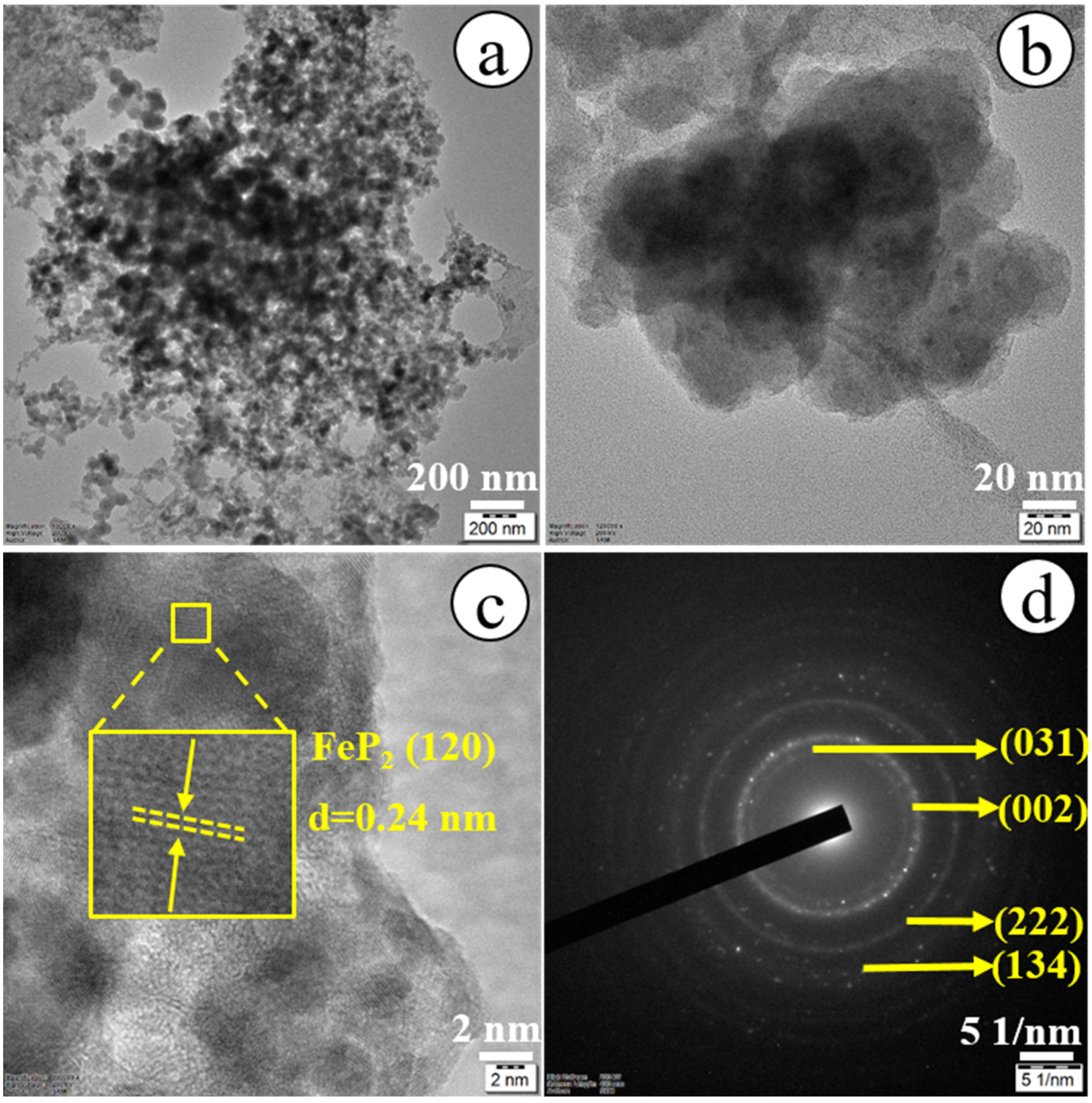
Figure 4 shows the TEM (a and b) and HRTEM images (c) and the SAED pattern (d) of the PS-3D-FeP@NiO nanostructures. As displayed in Figure 4a,b, the PS-3D-FeP@NiO showed 3-D nanosphere-like nanosheets with the average dimension of sphere of ~34.5 nm. Figure 4c displays the HRTEM image of the PS-3D-FeP@NiO nanostructures. The interplanar distance in the selected region is calculated to be ~0.24 nm, corresponding to the (120) crystal plane of the orthorhombic FeP2 [42]. The fabricated 3-D FeP@NiO nanosheets demonstrated the polycrystalline in nature, as evidenced by the SAED pattern of Figure 4d. The 3-D FeP@NiO nanosheets presented crystalline planes of (111), (211), and (222), which reveal the polycrystallinity [42,46].
The surface elemental valence states and the elemental composition of the developed electrodes were studied by using X-ray photoelectron spectroscopy (XPS). Figure 5a displays the complete XPS survey for PS-3D-FeP@NiO|Ni electrode and confirms the presence of Fe, P, and O. As depicted in Figure 5b, a couple of XPS peaks located at 708.3 eV and 712.6 eV related with Fe 2p3/2 and Fe 2p1/2, respectively, suggested the existence of Fe3+. A broad XPS peak at 726.9 eV is ascribed to Fe2+ (Fe 2p1/2 spin-orbit) in the PS-3D-FeP@NiO|Ni electrode. Additionally, another peak at 717.9 eV is associated to the satellite peak of Fe 2p. Among them, the XPS peak obtained at 726.9 eV arises from FeP chemical bonds, representing that P-doped Fe, which is gamely oxidized in atmosphere to develop metallic phosphate as well as the deposited Fe, exists as Fe2+ or Fe3+ [9,47,48]. As depicted in Figure 5c, two peaks in the P 2p region located at 132.4 eV (P 2p3/2) and 133.6 eV (P 2p1/2), attributed to phosphide (P) in 3-D FeP-NiO nanosheets electrode [49]. In the region of O 1s (Figure 5d), the XPS peaks at 531.1, 532.0, and 532.6 eV corresponded to the O–Fe bond, -OH bond (or O- imperfections locations), and adsorbent material oxygen at or near the electrode surface, respectively [9,31].

3.2. Electrochemical Characterization of PS-3D-FeP@NiO Nanostructures

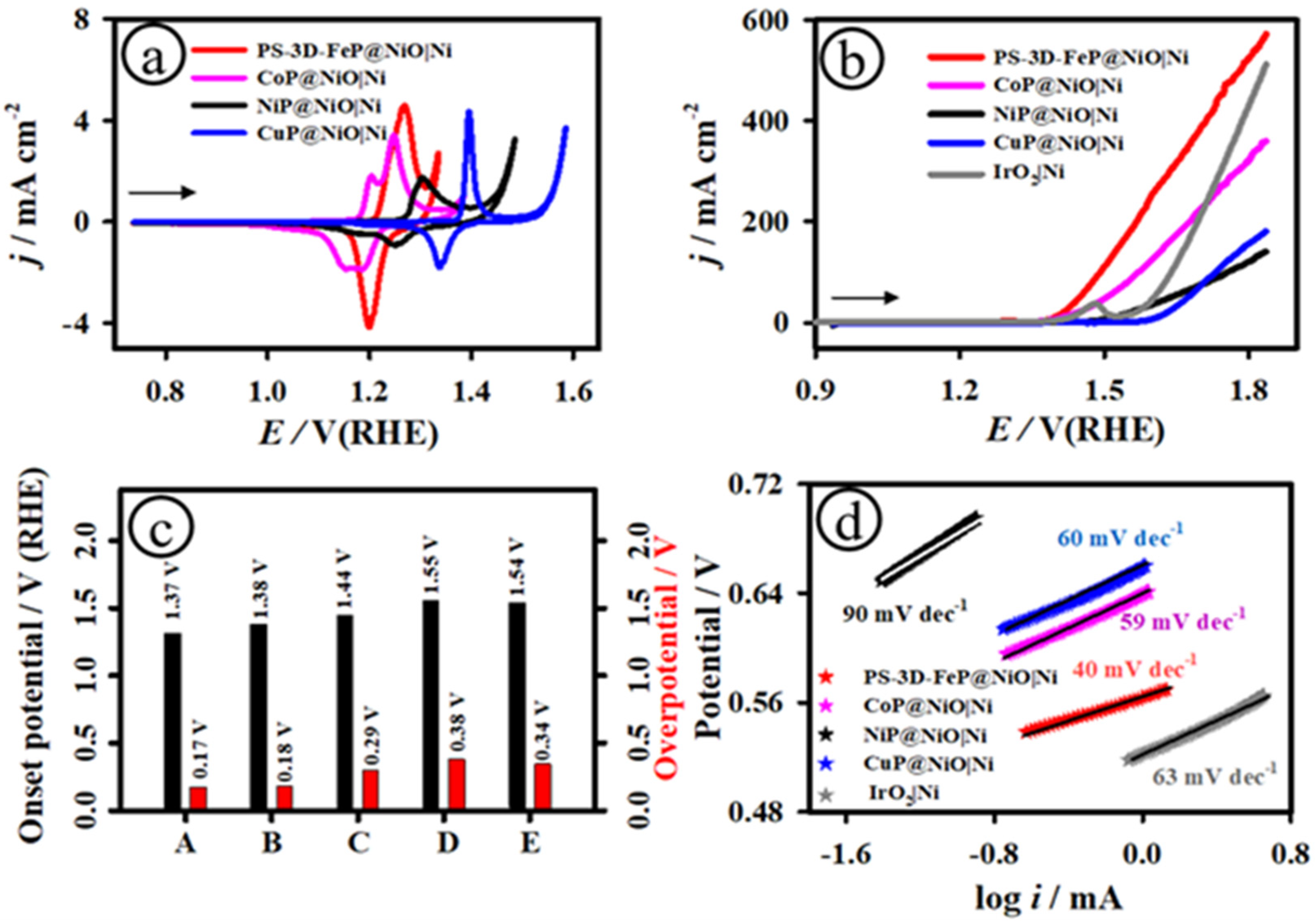
Figure 6a depicts the cyclic voltammetric (CV) curves of the PS-3D-FeP@NiO|Ni (red curve), CoP@NiOǀNi (pink curve), NiP@NiOǀNi (black curve), and CuP@NiOǀNi (blue curve) recorded in 1.0 M KOH electrolyte at the scan rate of 20 mV s−1 in the operating potential window of 0.74–1.64 V (vs. RHE). As shown in Figure 6a, all the as-developed electrodes presented the electrochemical redox behavior in the potential range of 1.0–1.5 V. The PS-3D-FeP@NiO|Ni electrode exhibited a strong anodic peak at ~1.27 V and cathodic peak at ~1.21 V, attributed to Fe2+/Fe3+ couple [50]. The CoP@NiOǀNi electrode showed two pairs of electrochemical redox peaks obtained at ~1.19 V/~1.16 V and ~1.24 V/~1.19 V, ascribed to Co2+/Co3+ and Co3+/Co4+, respectively [51]. A pair of redox peaks was observed at ~1.29 V/~1.27 V for the NiP@NiOǀNi electrode, corresponding to Ni2+/Ni3+ [52]. The CuP@NiOǀNi electrode showed a sharp anodic peak at more positive potential of ~1.39 V and cathodic peak at ~1.34 V, associated to Cu2+/Cu3+ [53].

3.3. Electrochemical Catalytic OER Activity of PS-3D-FeP@NiO Nanostructures

Among all the developed electrodes, the PS-3D-FeP@NiO|Ni electrode demonstrated good redox behavior in terms of peak currents and less positive potential, favoring the electrocatalytic OER. Figure S3 shows the CV curves of the PS-3D-FeP@NiO|Ni electrode (a), CoP@NiOǀNi (b), NiP@NiOǀNi (c), and CuP@NiOǀNi (d) recorded in 1.0 M KOH at different scan rates, starting from 10 mV s−1 to 125.0 mV s−1. With increasing scan rate, the anodic and cathodic peak current densities steadily increased and maintained their shape. As depicted in Figure S4, the plot of anodic and cathodic current densities vs. the square route of scan rates showed a linear trend, indicating a mass transport process regulated by diffusion [54]. To investigate the electrocatalytic OER activity of the porous structured three-dimensional (3D) FeP nanosheets on NiO modified Ni electrode, several electrochemical techniques such as linear sweep voltammetric (LSV), chronoamperometric (CA), chronopotentiometric (CP), and electrochemical impedance spectroscopic (EIS) measurements were employed.
Figure 6b shows the LSV curves of the PS-3D-FeP@NiO|Ni (red curve), CoP@NiOǀNi (pink curve), NiP@NiOǀNi (black curve), CuP@NiOǀNi (blue curve), and commercial IrO2|Ni (gray curve) electrodes recorded in 1.0 M KOH electrolyte at a scan rate of 20 mV s−1 in the operating potential range of 0.9–1.8 V (vs. RHE). As shown in Figure 6b, c, the OER onset potential was measured to be ~1.37, ~1.38, ~1.44, ~1.55, and ~1.54 V for PS-3D-FeP@NiO|Ni, CoP@NiOǀNi, NiP@NiOǀNi, CuP@NiOǀNi, and IrO2|Ni electrodes, respectively. The value of overpotential (η) was measured at the current density of ~10.0 mA cm−2 to be ~0.17, ~0.18, ~0.29, ~0.38, ~0.34, and ~0.24 V for PS-3D-FeP@NiO|Ni, CoP@NiOǀNi, NiP@NiOǀNi, CuP@NiOǀNi, IrO2|Ni, and FeP|NF electrodes, respectively. Besides the OER onset potential and overpotential, the anodic current density was calculated at the potential of ~1.80 V to be ~580, ~365, ~145, ~185, ~516, and 310 mA cm−2 for PS-3D-FeP@NiO|Ni, CoP@NiOǀNi, NiP@NiOǀNi, CuP@NiOǀNi, IrO2|Ni, and FeP|NF electrodes, respectively. The porous structured 3D FeP nanosheets on NiO modified Ni electrode demonstrated a highest current density of ~580 mA cm−2 at ~1.80 V in comparison to other electrodes employed in the current investigation (Figure 6 and Figure S5). The PS-3D-FeP@NiO|Ni electrode exhibited higher OER catalytic current densities over ~1.6, ~4.0, ~3.1, and ~1.1-times greater than that of the CoP@NiOǀNi, NiP@NiOǀNi, CuP@NiOǀNi, and IrO2|Ni electrodes, respectively.
Figure 6d presents the Tafel plots of the PS-3D-FeP@NiO|Ni, CoP@NiOǀNi, NiP@NiOǀNi, CuP@NiOǀNi, and IrO2|Ni electrodes, which is fitted in the strongly polarized area of the LSV curves. It is understood that a smaller Tafel slope is beneficial for the practical application of catalysts in electrode materials because it leads to faster catalytic reaction kinetics and greater charge transfer abilities. The Tafel slope values for PS-3D-FeP@NiO|Ni, CoP@NiOǀNi, NiP@NiOǀNi, CuP@NiOǀNi, and IrO2|Ni electrodes were determined to be ~40.0, ~59.0, ~90.0, ~60.0 and ~63.0 mV dec−1, respectively. Among the developed electrodes in the present study, the PS-3D-FeP@NiO|Ni exhibited the smallest Tafel slope when compared to other electrodes, indicating the faster catalytic oxygen evolution kinetics and greater charge transfer abilities than other materials employed in this work.
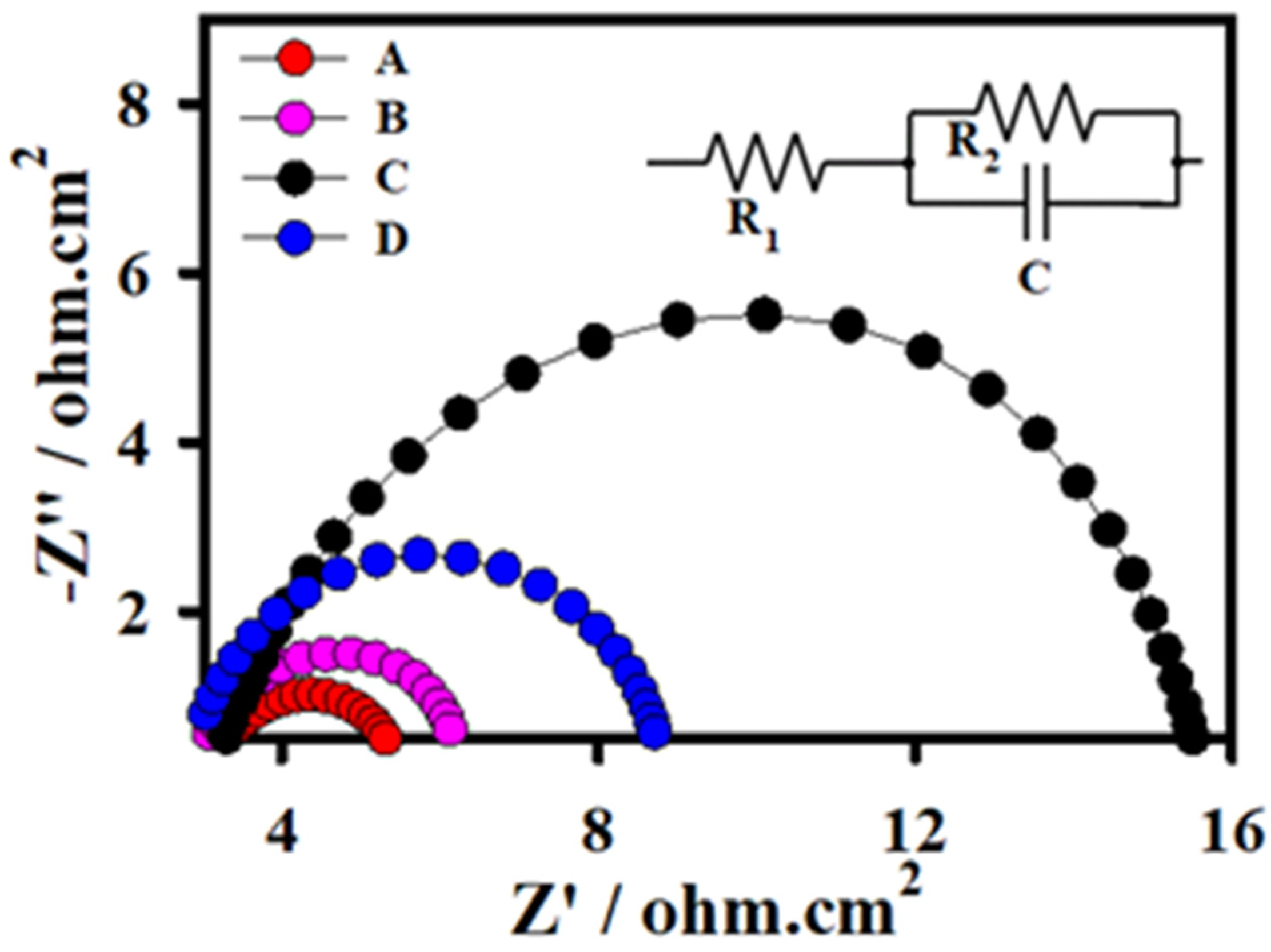
Figure 7 depicts the Nyquist plots of the PS-3D-FeP@NiO|Ni, CoP@NiOǀNi, NiP@NiOǀNi, and CuP@NiOǀNi electrodes at the applied potential of ~1.49 V. As shown in Figure 7, the PS-3D-FeP@NiO|Ni (A) exhibited the lowest polarization resistance (Rp) (~3.3 Ω) in comparison to other electrodes CoP@NiOǀNi (B) (~3.9 Ω), NiP@NiOǀNi (C) (~12.3 Ω), and CuP@NiOǀNi (D) (~6.5 Ω) electrodes developed in this study. In addition, the PS-3D-FeP@NiO|Ni demonstrated a high double layer capacitance (Cdl) of ~40. 5 mF cm−2, indicating accelerated charge transfer and mass diffusion processes at the electrode/electrolyte (Table S1).
Figure 8 displays the multi-step chronoamperometric (a) and chronopotentiometric (b) techniques to examine the electrocatalytic OER activity of the designed PS-3D-FeP@NiO|Ni nanostructured electrode at different applied potentials (Eapp) and applied currents (iapp) under alkaline electrolyte. The PS-3D-FeP@NiO|Ni electrode delivered high steady-state current density of ~55.1, ~123.2, ~195.3 and ~270.5 mA cm−2 at applied potentials of 1.58, 1.63, 1.68, and 1.73 V, respectively, as shown in Figure 8b. Furthermore, the PS-3D-FeP@NiO|Ni electrode exhibited low electrode potentials of ~1.58, ~1.62, ~1.66 and ~1.67 V at the applied current densities of ~50.0, ~100.0, ~150.0, and ~200.0 mA cm−2, respectively (Figure 8c,d). The electrochemical active surface area (ECASA) of the PS-3D-FeP@NiO|Ni electrode was calculated based on their double-layer capacitance (Cdl) and is shown in Figure S6. The value of Cdl was established to be 6.31 mF cm−2, revealed that the PS-3D-FeP@NiO|Ni electrode showed high double layer capacitance and a high ECASA due to the porous-structured 3D nanosheets-like surface morphology.
Based on these practical attentions, the OER CV curves were captured at the PS-3D-FeP@NiO|Ni electrode under 30% KOH electrolyte and are displayed in Figure S8. The CV and LSV curves of the PS-3D-FeP@NiO|Ni electrode delivered the overpotential of 0.20 V at a current density of 10 mA cm−2 (Figure S7). As summarized in Table 1, the as-developed PS-3D-FeP@NiO|Ni electrode delivered a lowest onset OER potential, overpotential, and high TOF values in comparison to other electrodes reported in the literature. The excellent OER electrocatalytic characteristics correspond to porous-structured 3D nanosheets of FeP@NiO on Ni electrode, which offer rich active sites, large volume of ECASA, and improved conductivity. In addition, the synergistic effect among FeP and NiO heterostructures would facilitate the charge transfer kinetics and ion diffusion.
The longstanding stability of the designed nanostructured PS-3D-FeP@NiO|Ni electrode was studied using chronopotentiometric measurements in 1.0 KOH for 24 h by operating a constant current density of ~10.0 mA cm−2 and is presented in Figure S9. After a 24-h continuous OER measurement, the PS-3D-FeP@NiO|Ni nanostructured electrode retained OER activity with an electrode potential of ~1.56 V, revealing good stability. The inset in Figure S8 displays the LSV curves of the three-brand new developed PS-3D-FeP@NiO|Ni electrodes recorded in 1.0 M KOH. As depicted in Figure S8 (inset), the PS-3D-FeP@NiO|Ni electrodes exhibited a stable polarization curve and delivered a similar overpotential of 0.172 V (red curve), 0.176 V (black curve), and 0.177 V (blue curve) at the current density of ~10.0 mA cm−2, suggesting good reproducibility.
As displayed in Figure 9 and Figure S9, the surface morphology of the 3D-FeP@NiO|Ni electrode had not altered after a long-term durability test conducted under an alkaline electrolyte. The EDS results suggested that the chemical composition, distribution of Fe, P and O, and crystalline structures were not altered significantly. The ECASA of the PS-3D-FeP@NiO|Ni electrode was calculated after a long-term durability test and is shown in Figure S10. The value of Cdl and ECASA was established to be 2.67 mF cm−2 and 66.7 cm2, respectively, revealing that the ECASA for PS-3D-FeP@NiO|Ni electrode was reduced after a long-term stability test due to the adsorption of intermediates on the catalyst surface.
Moreover, to demonstrate the practicability, full cell alkaline electrolysis was prepared using the PS-3D-FeP@NiO|Ni ǀǀ Pt/C couple in 1.0 M KOH. For the purpose of comparison, the state-of-the-art IrO2 ǀǀ Pt/C couple was also prepared. As depicted in Figure 10, the present PS-3D-FeP@NiO|Ni ǀǀ Pt/C (red curve) couple exhibited a low cell voltage of only ~1.66 V at a current density of 10 mA cm−2 and delivered a high current density of ~294.0 mA cm−2 at the potential of ~2.0 V, showing high performance for practical feasibility. On the other hand, the state-of-the-art IrO2 ǀǀ Pt/C couple (gray curve) delivered a cell potential of ~1.70 V at the current density of 10 mA cm−2 and exhibited the current density of ~219.0 mA cm−2 at the potential of ~2.0 V.

4. Conclusions

In summary, porous structured three-dimensional (3-D) FeP nanosheets on NiO modified Ni electrode is developed using of a simple method and two-step electrodeposition strategy. For comparison, a series of other nanostructured transition metal (cobalt, nickel, and copper)-derived phosphides on nickel oxide (NiO) modified Ni electrode is developed under similar experimental settings. The fabricated PS-3D-FeP@NiO|Ni electrode exhibits the best electrocatalytic activity towards OER under alkaline electrolyte with low onset potential (~1.37 V (vs. RHE)), small overpotential (η) (~0.17 V to produce the current densities of 10 mA cm−2), small Tafel slope (~40.0 mV dec−1), high turn-over frequency (TOF) (0.435 s−1), and long-term stability among the developed CoP@NiOǀNi, NiP@NiOǀNi, CuP@NiOǀNi, and commercial IrO2|Ni electrodes. The outclassing OER activity of PS-3D-FeP@NiO|Ni is allied to its porous-structured 3-D sheet-like morphology, a large quantity of electrochemical active surface area, high electrical conductance characteristics and self-activated/supported active sites, facilitating the catalytic properties towards OER. The surface morphology, crystalline structure, chemical composition, and distribution of Fe, P and O elements have not been altered significantly after a long-term OER test. This fabrication route may be expanded to produce a variety of bi-metallic and tri-metallic phosphides for electrochemical energy conversion and storage systems.

Supplementary Materials

The following are available online at https://www.mdpi.com/article/10.3390/en16031124/s1, Table S1. EIS data derived from Nyquist plots of Figure 7; Figure S1. HR-SEM images of FeP nanostructures with high (a) and low (b) magnification images; Figure S2. EDX spectra of the PS-3D-FeP@NiO|Ni (a), CoP@NiOǀNi (b), NiP@NiOǀNi (c), and CuP@NiOǀNi (d) electrodes; Figure S3. CV curves of the PS-3D-FeP@NiO|Ni (a), CoP@NiOǀNi (b), NiP@NiOǀNi (c), and CuP@NiOǀNi (d) electrodes recorded in 1.0 M KOH with the different scan rates, starting from 10 to 125 mV s1; Figure S4. The plot of anodic and cathodic peak current densities against the square root of the scan rates for PS-3D-FeP@NiO|Ni (a), CoP@NiOǀNi (b), NiP@NiOǀNi (c), and CuP@NiOǀNi (d); Figure S5. CV (a) and LSV (b) curves of the PS-3D-FeP@NiO|Ni (red curve) and FeP|NF (black curve) electrodes recorded in 1.0 M KOH electrolyte; Figure S6. (a) CVs of the PS-3D-FeP@NiO|Ni electrode recorded in 1.0 M KOH at different scan rates from 10 to 125 mV s1. (b) Plot of current density measured from non-faradaic region of the voltammograms against the function of the scan rates; Figure S7. CV curve (a) and LSV curves (b) of the PS-3D-FeP@NiO|Ni electrode recorded in 30% KOH. Figure S8. Chronopotentiometric curve of the PS-3D-FeP@NiO|Ni electrode recorded in 1.0 M KOH under applied current density of ~10.0 mAcm2. Inset: LSV curves of the PS-3D-FeP@NiO|Ni electrodes. Electrolyte: 1.0 M KOH; Scan rate of 20 mV s1; Figure S9. HR-SEM image (a), EDX spectra (b) and elemental mapping of Fe, P and O (c) for the PS-3D-FeP@NiO|Ni electrode measured after had a long-term stability test; Figure S10. (a) CVs of the PS-3D-FeP@NiO|Ni electrode recorded in 1.0 M KOH at different scan rates from 10 to 125 mV s1 measured after had a long-term stability test. (b) Plot of current density measured from non-faradaic region of the CVs against the function of the scan rates.

Author Contributions

G.M. designed the study; S.M. and A.S. performed the experimental work; S.M. analyzed the results and drafted the manuscript; G.M. discussed and corrected the manuscript. All authors have read and agreed to the published version of the manuscript.

Funding

This work was supported by a CPRI, Bangalore (Ref. No.: CPRI/R&D/TC/GDEC/2022).

Data Availability Statement

Not applicable.

Acknowledgments

We acknowledge by the SRM Institute of Science and Technology (SRM IST) for providing all the research facilities, including SRM-SCIF for HRTEM, HRSEM, and XRD measurements. This work was commercially supported by the Central Power Research Institute (CPRI), Bangalore (Ref.: CPRI/R&D/TC/GDEC/2022).

Conflicts of Interest

The authors declare no conflict of interest.

References

  1. Zhao, H.; Yuan, Z. Design Strategies of Transition-Metal Phosphate and Phosphonate Electrocatalysts for Energy-Related Reactions. ChemSusChem 2021, 14, 130–149. [Google Scholar] [CrossRef] [PubMed]
  2. Alsabban, M.M.; Eswaran, M.K.; Peramaiah, K.; Wahyudi, W.; Yang, X.; Ramalingam, V.; Hedhili, M.N.; Miao, X.; Schwingenschlögl, U.; Li, L.-J.; et al. Unusual Activity of Rationally Designed Cobalt Phosphide/Oxide Heterostructure Composite for Hydrogen Production in Alkaline Medium. ACS Nano 2022, 16, 3906–3916. [Google Scholar] [CrossRef] [PubMed]
  3. Yu, Z.Y.; Duan, Y.; Feng, X.Y.; Yu, X.; Gao, M.R.; Yu, S.H. Clean and Affordable Hydrogen Fuel from Alkaline Water Splitting: Past, Recent Progress, and Future Prospects. Adv. Mater. 2021, 33, 1–35. [Google Scholar] [CrossRef] [PubMed]
  4. Ganesan, V.; Son, J.; Kim, J. CoP2 /Fe-CoP2 Yolk–Shell Nanoboxes as Efficient Electrocatalysts for the Oxygen Evolution Reaction. Nanoscale 2021, 13, 4569–4575. [Google Scholar] [CrossRef] [PubMed]
  5. Yu, F.; Zhou, H.; Huang, Y.; Sun, J.; Qin, F.; Bao, J.; Goddard, W.A.; Chen, S.; Ren, Z. High-Performance Bifunctional Porous Non-Noble Metal Phosphide Catalyst for Overall Water Splitting. Nat. Commun. 2018, 9, 2551. [Google Scholar] [CrossRef] [PubMed] [Green Version]
  6. Zhang, A.; Xiao, Y.; Cao, Y.; Fang, H.; Zhang, Y.; Das, P.; Zhang, H. Electrodeposition, Formation Mechanism, and Electrocatalytic Performance of Co-Ni-P Ternary Catalysts Coated on Carbon Fiber Paper. J. Solid State Electrochem. 2021, 25, 1503–1512. [Google Scholar] [CrossRef]
  7. Li, D.; Zhou, C.; Yang, R.; Xing, Y.; Xu, S.; Jiang, D.; Tian, D.; Shi, W. Interfacial Engineering of the CoxP-Fe2P Heterostructure for Efficient and Robust Electrochemical Overall Water Splitting. ACS Sustain. Chem. Eng. 2021, 9, 7737–7748. [Google Scholar] [CrossRef]
  8. Lv, X.W.; Xu, W.S.; Tian, W.W.; Wang, H.Y.; Yuan, Z.Y. Activity Promotion of Core and Shell in Multifunctional Core–Shell Co2P@NC Electrocatalyst by Secondary Metal Doping for Water Electrolysis and Zn-Air Batteries. Small 2021, 17, 2101856. [Google Scholar] [CrossRef]
  9. Elakkiya, R.; Maduraiveeran, G. Iron Sulphide Rice Grain Nanostructures as Potential Electrocatalysts for an Improved Oxygen Evolution Reaction. Nanoscale 2021, 13, 14837–14846. [Google Scholar] [CrossRef]
  10. Zhang, L.; Chen, Y.; Liu, G.; Li, Z.; Liu, S.; Tiwari, S.K.; Ola, O.; Pang, B.; Wang, N.; Zhu, Y. Construction of CoP/Co2 P Coexisting Bifunctional Self-Supporting Electrocatalysts for High-Efficiency Oxygen Evolution and Hydrogen Evolution. ACS Omega 2022, 7, 12846–12855. [Google Scholar] [CrossRef]
  11. Guo, J.; Zhan, Z.; Lei, T.; Yin, P. Self-Supported FeNiP Nanosheet Arrays as a Robust Bifunctional Electrocatalyst for Water Splitting. ACS Appl. Energy Mater. 2022, 5, 5855–5866. [Google Scholar] [CrossRef]
  12. Chai, L.; Hu, Z.; Wang, X.; Xu, Y.; Zhang, L.; Li, T.; Hu, Y.; Qian, J.; Huang, S. Stringing Bimetallic Metal–Organic Framework-Derived Cobalt Phosphide Composite for High-Efficiency Overall Water Splitting. Adv. Sci. 2020, 7, 1903195. [Google Scholar] [CrossRef] [Green Version]
  13. Karmakar, A.; Karthick, K.; Kumaravel, S.; Sankar, S.S.; Kundu, S. Enabling and Inducing Oxygen Vacancies in Cobalt Iron Layer Double Hydroxide via Selenization as Precatalysts for Electrocatalytic Hydrogen and Oxygen Evolution Reactions. Inorg. Chem. 2021, 60, 2023–2036. [Google Scholar] [CrossRef] [PubMed]
  14. Marquez-Montes, R.A.; Kawashima, K.; Son, Y.J.; Weeks, J.A.; Sun, H.H.; Celio, H.; Ramos-Sánchez, V.H.; Mullins, C.B. Mass Transport-Enhanced Electrodeposition of Ni–S–P–O Films on Nickel Foam for Electrochemical Water Splitting. J. Mater. Chem. A 2021, 9, 7736–7749. [Google Scholar] [CrossRef]
  15. Gao, H.; Sun, W.; Tian, X.; Liao, J.; Ma, C.; Hu, Y.; Du, G.; Yang, J.; Ge, C. Amorphous–Amorphous Coupling Enhancing the Oxygen Evolution Reaction Activity and Stability of the NiFe-Based Catalyst. ACS Appl. Mater. Interfaces 2022, 14, 15205–15213. [Google Scholar] [CrossRef]
  16. Hafezi Kahnamouei, M.; Shahrokhian, S. Coupling NiCoS and CoFeS Frame/Cagelike Hybrid as an Efficient Electrocatalyst for Oxygen Evolution Reaction. ACS Appl. Energy Mater. 2022, 5, 5199–5211. [Google Scholar] [CrossRef]
  17. Asghar, M.A.; Ali, A.; Haider, A.; Zaheer, M.; Nisar, T.; Wagner, V.; Akhter, Z. Electrochemically Deposited Amorphous Cobalt-Nickel-Doped Copper Oxide as an Efficient Electrocatalyst toward Water Oxidation Reaction. ACS Omega 2021, 6, 19419–19426. [Google Scholar] [CrossRef] [PubMed]
  18. Wang, Q.; Xu, C.; Cai, W.; Chen, H.M.; Liu, W.; Hung, S.; Yang, H.B.; Li, J.; Liu, B. Coordination Engineering of Iridium Nanocluster Bifunctional Electrocatalyst for Highly Efficient and PH-Universal Overall Water Splitting. Nat. Commun. 2020, 11, 4246. [Google Scholar] [CrossRef]
  19. Li, M.; Zheng, K.; Zhang, J.; Li, X.; Xu, C. Design and Construction of 2D/2D Sheet-on-Sheet Transition Metal Sulfide/Phosphide Heterostructure for Efficient Oxygen Evolution Reaction. Appl. Surf. Sci. 2021, 565, 150510. [Google Scholar] [CrossRef]
  20. Li, R.; Li, Y.; Yang, P.; Wang, D.; Xu, H.; Wang, B.; Meng, F.; Zhang, J.; An, M. Electrodeposition: Synthesis of Advanced Transition Metal-Based Catalyst for Hydrogen Production via Electrolysis of Water. J. Energy Chem. 2021, 57, 547–566. [Google Scholar] [CrossRef]
  21. Díaz-Sainz, G.; Fernández-Caso, K.; Lagarteira, T.; Delgado, S.; Alvarez-Guerra, M.; Mendes, A.; Irabien, A. Coupling Continuous CO2 Electroreduction to Formate with Efficient Ni-Based Anodes. J. Environ. Chem. Eng. 2023, 11, 109171. [Google Scholar] [CrossRef]
  22. Zhao, J.; Zhang, J.; Li, Z.; Bu, X. Recent Progress on NiFe-Based Electrocatalysts for the Oxygen Evolution Reaction. Small 2020, 16, 2003916. [Google Scholar] [CrossRef] [PubMed]
  23. Sayed, D.M.; El-Nagar, G.A.; Sayed, S.Y.; El-Anadouli, B.E.; El-Deab, M.S. Activation/Deactivation Behavior of Nano-NiOx Based Anodes towards the OER: Influence of Temperature. Electrochim. Acta 2018, 276, 176–183. [Google Scholar] [CrossRef]
  24. Cai, Z.; Bu, X.; Wang, P.; Ho, J.C.; Yang, J.; Wang, X. Recent Advances in Layered Double Hydroxide Electrocatalysts for the Oxygen Evolution Reaction. J. Mater. Chem. A 2019, 7, 5069–5089. [Google Scholar] [CrossRef]
  25. Wang, D.; Zhang, Y.; Fei, T.; Mao, C.; Song, Y.; Zhou, Y.; Dong, G. NiCoP/NF 1D/2D Biomimetic Architecture for Markedly Enhanced Overall Water Splitting. ChemElectroChem 2021, 8, 3064–3072. [Google Scholar] [CrossRef]
  26. Pu, Z.; Liu, T.; Amiinu, I.S.; Cheng, R.; Wang, P.; Zhang, C.; Ji, P.; Hu, W.; Liu, J.; Mu, S. Transition-Metal Phosphides: Activity Origin, Energy-Related Electrocatalysis Applications, and Synthetic Strategies. Adv. Funct. Mater. 2020, 30, 2004009. [Google Scholar] [CrossRef]
  27. Yaqoob, L.; Noor, T.; Iqbal, N.; Nasir, H.; Zaman, N.; Talha, K. Electrochemical Synergies of Fe–Ni Bimetallic MOF CNTs Catalyst for OER in Water Splitting. J. Alloys Compd. 2021, 850, 156583. [Google Scholar] [CrossRef]
  28. Wang, M.; Zhang, L.; He, Y.; Zhu, H. Recent Advances in Transition-Metal-Sulfide-Based Bifunctional Electrocatalysts for Overall Water Splitting. J. Mater. Chem. A 2021, 9, 5320–5363. [Google Scholar] [CrossRef]
  29. Ibn Shamsah, S.M. Earth-Abundant Electrocatalysts for Water Splitting: Current and Future Directions. Catalysts 2021, 11, 429. [Google Scholar] [CrossRef]
  30. Jiang, Y.; Lu, Y. Designing Transition-Metal-Boride-Based Electrocatalysts for Applications in Electrochemical Water Splitting. Nanoscale 2020, 12, 9327–9351. [Google Scholar] [CrossRef]
  31. Liu, J.; Gao, Y.; Wei, Y.; Chen, X.; Hao, S.; Ding, X.; Pan, L. A Highly Efficient FeP/CeO2 –NF Hybrid Electrode for the Oxygen Evolution Reaction. Chem. Commun. 2020, 56, 4228–4231. [Google Scholar] [CrossRef] [PubMed]
  32. Huang, C.; Zou, Y.; Ye, Y.-Q.; Ouyang, T.; Xiao, K.; Liu, Z.-Q. Unveiling the Active Sites of Ni–Fe Phosphide/Metaphosphate for Efficient Oxygen Evolution under Alkaline Conditions. Chem. Commun. 2019, 55, 7687–7690. [Google Scholar] [CrossRef] [PubMed]
  33. Wu, L.; Yu, L.; Zhang, F.; McElhenny, B.; Luo, D.; Karim, A.; Chen, S.; Ren, Z. Heterogeneous Bimetallic Phosphide Ni2P-Fe2P as an Efficient Bifunctional Catalyst for Water/Seawater Splitting. Adv. Funct. Mater. 2021, 31, 1–12. [Google Scholar]
  34. Zhang, H.; Maijenburg, A.W.; Li, X.; Schweizer, S.L.; Wehrspohn, R.B. Bifunctional Heterostructured Transition Metal Phosphides for Efficient Electrochemical Water Splitting. Adv. Funct. Mater. 2020, 30, 2003261. [Google Scholar] [CrossRef]
  35. Dondapati, J.S.; Govindhan, M.; Chen, A. Direct Growth of Three-Dimensional Nanoflower-like Structures from Flat Metal Surfaces. Chem. Commun. 2022, 58, 11127–11130. [Google Scholar] [CrossRef]
  36. Zhang, J.; Shewale, P.S.; Yun, K.S. Fiber-Shaped Supercapacitors Fabricated Using Hierarchical Nanostructures of NiCo2O4 Nanoneedles and MnO2 Nanoflakes on Roughened Ni Wire. Energies 2019, 12, 3127. [Google Scholar] [CrossRef] [Green Version]
  37. Arivazhagan, M.; Maduraiveeran, G. Hierarchical Gold Dispersed Nickel Oxide Nanodendrites Microarrays as a Potential Platform for the Sensitive Electrochemical Detection of Glucose and Lactate in Human Serum and Urine. Mater. Chem. Phys. 2023, 295, 127084. [Google Scholar] [CrossRef]
  38. Shi, Y.; Huang, W.-M.; Li, J.; Zhou, Y.; Li, Z.-Q.; Yin, Y.-C.; Xia, X.-H. Site-Specific Electrodeposition Enables Self-Terminating Growth of Atomically Dispersed Metal Catalysts. Nat. Commun. 2020, 11, 4558. [Google Scholar] [CrossRef]
  39. Shankar, A.; Maduraiveeran, G. Hierarchical Bimetallic Iron-Cobalt Phosphides Nano-Island Nanostructures for Improved Oxygen Evolution Reaction. J. Electroanal. Chem. 2022, 923, 116806. [Google Scholar] [CrossRef]
  40. Jadhav, R.G.; Singh, D.; Krivoshapkin, P.V.; Das, A.K. Electrodeposited Organic–Inorganic Nanohybrid as Robust Bifunctional Electrocatalyst for Water Splitting. Inorg. Chem. 2020, 59, 7469–7478. [Google Scholar] [CrossRef]
  41. Chen, J.; Zhao, G.; Chen, Y.; Rui, K.; Mao, H.; Dou, S.X.; Sun, W. Iron-Doped Nickel Molybdate with Enhanced Oxygen Evolution Kinetics. Chem.-A Eur. J. 2019, 25, 280–284. [Google Scholar] [CrossRef] [PubMed]
  42. Jiang, J.; Wang, C.; Zhang, J.; Wang, W.; Zhou, X.; Pan, B.; Tang, K.; Zuo, J.; Yang, Q. Synthesis of FeP2 /C Nanohybrids and Their Performance for Hydrogen Evolution Reaction. J. Mater. Chem. A 2015, 3, 499–503. [Google Scholar] [CrossRef]
  43. Wu, T.; Pi, M.; Wang, X.; Zhang, D.; Chen, S. Three-Dimensional Metal–Organic Framework Derived Porous CoP3 Concave Polyhedrons as Superior Bifunctional Electrocatalysts for the Evolution of Hydrogen and Oxygen. Phys. Chem. Chem. Phys. 2017, 19, 2104–2110. [Google Scholar] [CrossRef] [PubMed]
  44. Li, H.; Lu, S.; Sun, J.; Pei, J.; Liu, D.; Xue, Y.; Mao, J.; Zhu, W.; Zhuang, Z. Phase-Controlled Synthesis of Nickel Phosphide Nanocrystals and Their Electrocatalytic Performance for the Hydrogen Evolution Reaction. Chem.-A Eur. J. 2018, 24, 11748–11754. [Google Scholar] [CrossRef]
  45. Chandrasekar, M.S.; Mitra, S. Thin Copper Phosphide Films as Conversion Anode for Lithium-Ion Battery Applications. Electrochim. Acta 2013, 92, 47–54. [Google Scholar] [CrossRef]
  46. Wang, Y.; Ma, B.; Chen, Y. Iron Phosphides Supported on Three-Dimensional Iron Foam as an Efficient Electrocatalyst for Water Splitting Reactions. J. Mater. Sci. 2019, 54, 14872–14883. [Google Scholar] [CrossRef]
  47. Yan, P.; Hu, Y.; Shoko, E.; Isimjan, T.T.; Tian, J.; Yang, X. Hierarchical Core-Shell N-Doped Carbon@FeP4 -CoP Arrays as Robust Bifunctional Electrocatalysts for Overall Water Splitting at High Current Density. Adv. Mater. Interfaces 2021, 8, 2100065. [Google Scholar] [CrossRef]
  48. Ju, Y.; Feng, S.; Wang, X.; Li, M.; Wang, L.; Xu, R.; Wang, J. Facile Preparation of a Porous Nanosheet P X -Doped Fe Bi-Functional Catalyst with Excellent OER and HER Electrocatalytic Activity. ChemistrySelect 2021, 6, 4979–4990. [Google Scholar] [CrossRef]
  49. Chen, Z.; Chen, W.; Jia, D.; Liu, Y.; Zhang, A.; Wen, T.; Liu, J.; Ai, Y.; Song, W.; Wang, X. N, P, and S Codoped Graphene-Like Carbon Nanosheets for Ultrafast Uranium (VI) Capture with High Capacity. Adv. Sci. 2018, 5, 1800235. [Google Scholar] [CrossRef]
  50. Li, R.; Qin, Y.; Tong, X. Synthesis of Iron Phosphide Nanoclusters by an Electroless Plating Method for Enhanced Oxygen Evolution Reaction. J. Electron. Mater. 2021, 50, 3071–3077. [Google Scholar] [CrossRef]
  51. Tang, Y.; Li, X.; Lv, H.; Xie, D.; Wang, W.; Zhi, C.; Li, H. Stabilized Co3+/Co4+ Redox Pair in In Situ Produced CoSe2− x -Derived Cobalt Oxides for Alkaline Zn Batteries with 10 000-Cycle Lifespan and 1.9-V Voltage Plateau. Adv. Energy Mater. 2020, 10, 2000892. [Google Scholar] [CrossRef]
  52. Msp, S.; Gnanasekaran, G.; Pazhamalai, P.; Sahoo, S.; Hossain, M.M.; Bhattarai, R.M.; Kim, S.-J.; Mok, Y.S. Hierarchically Porous Nanostructured Nickel Phosphide with Carbon Particles Embedded by Dielectric Barrier Discharge Plasma Deposition as a Binder-Free Electrode for Hybrid Supercapacitors. ACS Sustain. Chem. Eng. 2019, 7, 14805–14814. [Google Scholar]
  53. Prakash, V.; Srivastava, K.; Prasad, J. Cyclic Voltammetric Behavior of Binary and Mixed Ligand Copper Complexes with Picolinic Acid, Nicotinic Acid and Diethyldithiocarbamate in Acetone Medium. J. Indian Chem. Soc. 2019, 96, 585–591. [Google Scholar]
  54. Shankar, A.; Elakkiya, R.; Maduraiveeran, G. Self-Supported Fabrication and Electrochemical Water Splitting Study of Transition-Metal Sulphide Nanostructured Electrodes. New J. Chem. 2020, 44, 5071–5078. [Google Scholar] [CrossRef]
  55. Duan, D.; Guo, D.; Gao, J.; Liu, S.; Wang, Y. Electrodeposition of Cobalt-Iron Bimetal Phosphide on Ni Foam as a Bifunctional Electrocatalyst for Efficient Overall Water Splitting. J. Colloid Interface Sci. 2022, 622, 250–260. [Google Scholar] [CrossRef]
  56. Ganesan, P.; Sivanantham, A.; Shanmugam, S. Inexpensive Electrochemical Synthesis of Nickel Iron Sulphides on Nickel Foam: Super Active and Ultra-Durable Electrocatalysts for Alkaline Electrolyte Membrane Water Electrolysis. J. Mater. Chem. A 2016, 4, 16394–16402. [Google Scholar] [CrossRef] [Green Version]
  57. Man, H.-W.; Tsang, C.-S.; Li, M.M.-J.; Mo, J.; Huang, B.; Lee, L.Y.S.; Leung, Y.; Wong, K.-Y.; Tsang, S.C.E. Tailored Transition Metal-Doped Nickel Phosphide Nanoparticles for the Electrochemical Oxygen Evolution Reaction (OER). Chem. Commun. 2018, 54, 8630–8633. [Google Scholar] [CrossRef]
  58. Kale, S.B.; Babar, P.T.; Kim, J.H.; Lokhande, C.D. Synthesis of One Dimensional Cu2S Nanorods Using a Self-Grown Sacrificial Template for the Electrocatalytic Oxygen Evolution Reaction (OER). New J. Chem. 2020, 44, 8771–8777. [Google Scholar] [CrossRef]
  59. Li, G.; Yang, Q.; Rao, J.; Fu, C.; Liou, S.; Auffermann, G.; Sun, Y.; Felser, C. In Situ Induction of Strain in Iron Phosphide (FeP2 ) Catalyst for Enhanced Hydroxide Adsorption and Water Oxidation. Adv. Funct. Mater. 2020, 30, 1907791. [Google Scholar] [CrossRef] [Green Version]
  60. Elakkiya, R.; Maduraiveeran, G. Two-Dimensional Earth-Abundant Transition Metal Oxides Nanomaterials: Synthesis and Application in Electrochemical Oxygen Evolution Reaction. Langmuir 2020, 36, 4728–4736. [Google Scholar] [CrossRef]
  61. Kumar, L.; Antil, B.; Kumar, A.; Das, M.R.; Deka, S. A Superior and Stable Electrocatalytic Oxygen Evolution Reaction by One-Dimensional FeCoP Colloidal Nanostructures. ACS Appl. Mater. Interfaces 2022, 14, 5468–5477. [Google Scholar] [CrossRef] [PubMed]
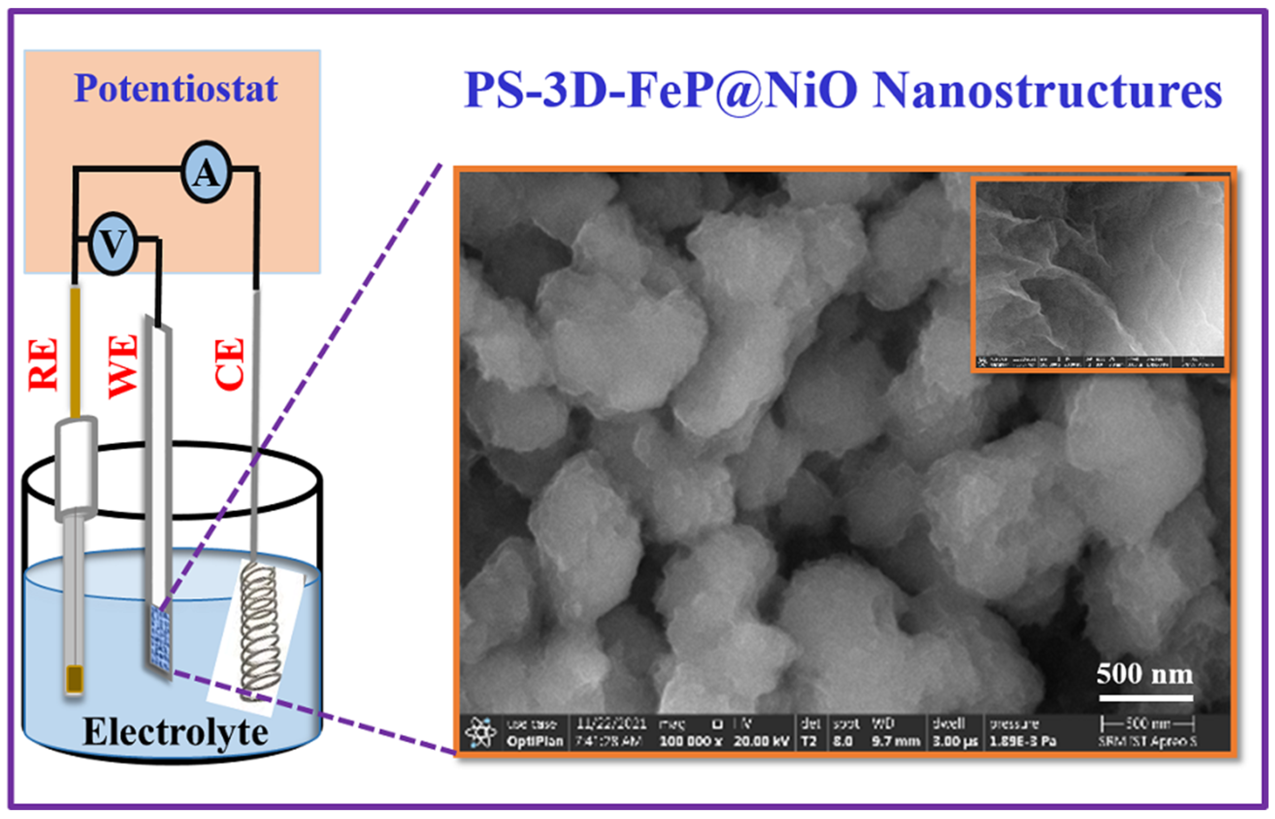
Scheme 1. The schematic illustration of electrochemical process of the fabrication of PS-3D-FeP@NiO nanostructures.
Energies 16 01124 sch001
Figure 1. XRD pattern of the PS-3D-FeP@NiO|Ni (a), CoP@NiOǀNi (b), NiP@NiOǀNi (c), and CuP@NiOǀNi (d) nanostructured electrodes. The other XRD peaks were marked with a star (*) and triangle (∆) endorsed to the Ni and NiO electrode.
Energies 16 01124 g001
Figure 2. HR-SEM images of the PS-3D-FeP@NiO|Ni (a), CoP@NiOǀNi (b), NiP@NiOǀNi (c), and CuP@NiOǀNi (d) nanostructured electrodes.
Energies 16 01124 g002
Figure 3. Elemental mapping of the PS-3D-FeP@NiO|Ni (a,b), CoP@NiOǀNi (c,d), NiP@-NiOǀNi (e,f), and CuP@NiOǀNi (g,h) electrodes.
Energies 16 01124 g003
Figure 4. TEM image (a,b), HR-TEM (c), and SAED (d) pattern of the PS-3D-FeP@NiO nanostructures.
Energies 16 01124 g004
Figure 5. (a) XPS survey spectrum of the FeP and high-resolution XPS spectra of (b) Fe 2p, (c) P 2p, and (d) O 1s spectra.
Energies 16 01124 g005
Figure 6. CV (a) and LSV (b) curves of the various electrodes including PS-3D-FeP@NiO|Ni (red curve), CoP@NiOǀNi (pink curve), NiP@NiOǀNi (black curve), and CuP@NiOǀNi (blue curve) electrodes recorded in 1.0 M KOH at the scan rate of 20 mVs−1. (The arrow indicates the potential cycle started) (c) The plot of onset potentials (Eonset) and overpotential measured at 10 mA cm−2 for PS-3D-FeP@NiO|Ni (A), CoP@NiOǀNi (B), NiP@NiOǀNi (C), CuP@NiOǀNi (D), and IrO|Ni (E) electrodes. (d) Tafel plots of the PS-3D-FeP@NiO|Ni, CoP@NiOǀNi, NiP@NiOǀNi, and CuP@NiOǀNi electrodes.
Energies 16 01124 g006
Figure 7. Nyquist plots of the nanostructured PS-3D-FeP@NiO|Ni (A) (red curve), CoP@NiOǀNi (B) (pink curve), NiP@NiOǀNi (C) (black curve), and CuP@NiOǀNi (D) (blue curve) electrodes recorded at the applied potential of ~1.49 V in 1.0 M KOH.
Energies 16 01124 g007
Figure 8. (a) Chronoamperometric response of the PS-3D-FeP@NiO|Ni electrode at different applied potentials of ~1.58, ~1.63, ~1.68, and ~1.73 V (vs. RHE); (b) The plot of the measured current density of the PS-3D-FeP@NiO|Ni electrode vs. different applied potentials; (c) Chronopotentiometric response of the PS-3D-FeP@NiO|Ni electrode at different applied current densities of ~50, ~100, ~150 and ~200 mA cm−2. (d) The plot of the measured electrode potential of the PS-3D-FeP@NiO|Ni electrode vs. different applied current densities.
Energies 16 01124 g008
Figure 9. TEM images of the low magnification (a) and high magnification (b), HRTEM image (c), and SAED pattern (d) for the PS-3D-FeP@NiO|Ni electrode measured after a long-term stability test.
Energies 16 01124 g009
Figure 10. LSV curves of the PS-3D-FeP@NiO|Ni||Pt/C (red curve) and state-of-the-art IrO2|Ni||Pt/C (grey curve) couple for overall water splitting recorded in 1.0 M KOH at a scan rate of 20 mV s−1.
Energies 16 01124 g010
Table 1. Comparison of the OER performance of the developed PS-3D-FeP@NiO|Ni electrode with the recently reported catalysts.
ElectrodesOverpotential
Ƞ (V)
Current Density
(mA cm−2 )
Tafel Slope (mV dec−1)Mass Activity
(A g−1)
TOF
(s−1)
ElectrolyteRef.
FeS0.321069 79.9-1.0 M KOH[54]
CoFe-P/NF0.281043.2--1.0 M KOH[55]
NiFeS-1/NF0.2310055276 0.5201.0 M KOH[56]
NiFeP0.332039--1.0 M KOH [57]
Cu2S/Cu0.2710128--1.0 M KOH[58]
strained FeP20.241056 --1.0 M KOH [59]
Co3O4 nanosheet0.381052112.30.0991.0 M KOH[60]
FeCoP0.2610054--1.0 M KOH[61]
PS-3D-FeP@NiO|Ni0.171040100.00.4351.0 M KOHThis study
NF-Nickel Foam; NP-Nanoporous; Pi-Phosphide; PS-Porous structure.
Disclaimer/Publisher’s Note: The statements, opinions and data contained in all publications are solely those of the individual author(s) and contributor(s) and not of MDPI and/or the editor(s). MDPI and/or the editor(s) disclaim responsibility for any injury to people or property resulting from any ideas, methods, instructions or products referred to in the content.