Article

A Generic Framework for Multiscale Simulation of High and Low Enthalpy Fractured Geothermal Reservoirs under Varying Thermodynamic Conditions

1
School of Environmental Studies, China University of Geosciences, Wuhan 430078, China
2
Department of Applied Mathematics, Faculty of Electrical Engineering, Mathematics and Computer Science, Delft University of Technology, 2628XE Delft, The Netherlands
3
Department of Geoscience and Engineering, Faculty of Civil Engineering and Geosciences, Delft University of Technology, 2628CV Delft, The Netherlands
*
Authors to whom correspondence should be addressed.
Energies 2023, 16(2), 928; https://doi.org/10.3390/en16020928
Submission received: 8 December 2022 / Revised: 10 January 2023 / Accepted: 11 January 2023 / Published: 13 January 2023
(This article belongs to the Special Issue Recent Advances in Reservoir Simulation)

Abstract

:
We develop a multiscale simulation strategy, namely, algebraic dynamic multilevel (ADM) method, for simulation of fluid flow and heat transfer in fractured geothermal reservoirs under varying thermodynamic conditions. Fractures with varying conductivities are modeled using the projection-based embedded discrete fracture model (pEDFM) in an explicit manner. The developed ADM method allows the fine-scale system to be mapped to a discrete domain with an adaptive grid resolution via the use of the restriction and prolongation operators. The developed framework is used (a) to investigate the impacts of formulations with different primary variables on the simulation results, and (b) to assess the performance of ADM in a high-enthalpy reservoir by comparing the simulation results against those obtained from fine-scale grids. Results show that the two formulations produce similar results in the case of single-phase flow, which indicates that the molar formulation is a favorable option that can be applied to varying thermodynamic conditions. Moreover, the ADM can provide accurate solutions with only a fraction of fine-scale grids, e.g., for the studied case, the maximum error is by average 1.3 with only 42% of active cells, thereby improving the computational efficiency. This is promising for applying the developed method to field-scale geothermal systems.

1. Introduction

The demand of geothermal energy is expected to increase within the next decades due to its high potential of sustainability [1,2,3]. The successful development of geothermal fields counts on accurate predictions of fluid and heat transport via the use of numerical simulations. However, there are key challenges in achieving such simulations. The spatial heterogeneity in rock properties, such as porosity and permeability, across multiple scales poses computational complexity which may result in poor convergence. Moreover, the fracture networks, which have been observed in many geothermal reservoirs, add to the complexity of the system further [4,5,6,7]. Fractures can act as either highly conductive flow channels, or impermeable faults blocking the flow. Additionally, their mechanical (thermoelastic) responses due to changes in temperature and pressure may alter their apertures [8,9]. Hence, they are expected to impact the heat production significantly. On the other hand, geothermal reservoirs can be categorized into different types with varying thermodynamic behaviors. In the case of high-enthalpy systems where multi-phase flow can occur, the convergence behavior becomes more severe [10,11]. These challenges emphasize the necessity of developing an advanced numerical framework that provides robust performance and high computational efficiency.
Several simulators have been developed for geothermal applications. TOUGH2 [12], which was developed for geothermal reservoir engineering originally, has been widely used in geothermal projects [13]. TOUGH2 employs the natural formulation in which pressure and temperature are primary variables. The AD-GPRS also provides geothermal capabilities [14]. Both natural and molar formulations are implemented, where the molar formulation takes pressure and enthalpy as primary variables. Recent development includes DARTS [10], in which the molar formulation is employed. A comparison study on the non-linear performance between both formulations has been performed [15], which concludes that there is no apparent preference in terms of formulation and the performance is largely dependent on the complexity of the model problem. Nevertheless, for the fractured system, the difference between the two formulations remains relatively unexplored. In addition, the large size of field-scale geothermal reservoirs demands imposing a large number of computational grids, which challenges the computational performance of conventional numerical models. An advanced solution strategy is, therefore, necessary to accelerate solving highly non-linear systems with systematic control of error.
Multiscale methods have been developed to solve the elliptic (or parabolic) pressure equation efficiently by constructing a coarse-scale system in which the fine-scale heterogeneities are preserved [16,17,18]. The full domain is divided into a set of coarser grid cells and the local solution, i.e., the basis function, is computed for each coarse grid cell. The system is then solved on a coarse grid resolution which will be mapped to the fine-scale resolution using the basis function. To improve the accuracy, iterative multiscale techniques have been introduced which allows for a systematic reduction of the error in the multiscale approximation [19]. Moreover, higher computational efficiency is achieved by using an algebraic framework for multiscale methods [20]. In the algebraic framework, the mapping between fine-scale and coarse-scale resolution is completed by using the prolongation and restriction operators. The prolongation operator, responsible for mapping from coarse-scale to fine-scale, contains locally computed basis functions. The restriction operator, on the contrary, maps from fine-scale to coarse-scale using the finite volume approach to ensure mass conservation. The local grid refinement (LGR), or dynamic LGR, is another technique that employs fine-scale grids in the computational domain where needed [21,22,23,24,25,26]. The algebraic dynamic multilevel (ADM) method is developed by extending the LGR and exploiting the basis functions from only one level into multiple levels to increase the efficiency even further [27,28,29].
In this work, the ADM method is developed for coupled mass–heat flow in fractured geothermal reservoirs for both high- and low-enthalpy systems. Due to the high non-linearity of the system (arising from the strong mass–heat coupling), the mass balance and the energy balance equations are coupled together using the fully implicit method (FIM). The projection-based embedded discrete fracture model (pEDFM) is used to explicitly represent fractures with varying permeability contrast comparing the hosting rock matrix. The discretized system of equations is obtained for the two primary unknowns (depending on the formulation) at fine-scale resolution. It is worth mentioning that the local thermal equilibrium is assumed to be valid in the simulation. This indicates the fluid and the hosting rock have identical temperatures at each grid cell, which is considered a safe assumption for the majority of the applications because of the large contact area between the liquid and solid phases [30]. It should be noted that analytical expressions have been developed to determine whether the fractured system satisfies the local thermal equilibrium [31]. Specifically, an idealized reservoir in which the matrix is intersected by two sets of fractures perpendicular to each other is considered. The resulting criterion, however, may not be appropriate for the system with complex fracture geometries.
This paper is structured as follows. First, the governing equations along with the choice of primary variables are presented. Next, the pEDFM implementation is covered, followed by a discussion on the ADM strategy. The two test cases are then presented to investigate the impact of formulations on simulation results, and to examine the performance of the ADM method, respectively. We close with the key findings of this work.

2. Materials and Methods

For a geothermal system, the flow can be either single-phase or multi-phase depending on thermodynamic conditions. In the case of low-enthalpy system, the phase change, i.e., evaporation of liquid phase into vapor phase and vice versa, does not occur. On the other hand, in high-enthalpy systems, due to more intense thermodynamic conditions, phase change may happen when fluid is subject to sudden changes in pressure or temperature. Here, we consider a general multi-phase formulation. The conservation law for each phase is added together to form one equation for the entire domain.

2.1. Mass and Energy Balance

The equation for conservation of mass for a single-component (water) multi-phase system is given by
t ϕ α ρ α S α m · α ρ α λ α · p m = ρ α q α m , w + α i ρ α q α m , f i ,
for matrix ( m ) and
t ϕ α ρ α S α f i · α ρ α λ α · p f i = ρ α q α f i , w + α ρ α q α f i , m + α j ρ α q α f i , f j j i ,
for the fracture ( f i ). In these equations, subscript α denotes the phase (either vapor or liquid phase); superscripts m , f i , and w refer to the rock matrix, the i -th fracture, and the well, respectively. ϕ is rock porosity, λ α is phase mobility expressed as λ α = k k r , α / μ α , where k is the absolute permeability of the rock, k r , α and μ α are the relative permeability and viscosity of phase α . Additionally, ρ α and S α are the phase density and saturation. q α m , f i and q α f i , m are the flux exchanges between matrix and fractures, and q α f i , f j are the flux exchange between intersecting fractures i and j . The well flux, i.e., q α m , w , is calculated using Peaceman well model.
The energy balance equation assuming local equilibrium is given by
t ρ U eff m · α ρ α h α λ α · p m · Λ eff · T m = ρ α h α q α m , w + α i ρ α h α q α m , f i + i r m , f i ,
for matrix ( m ) and
t ρ U eff f i · α ρ α h α λ α · p f i · Λ eff · T f i = ρ α h α q α f i , w + α ρ α h α q α f i , m + α j ρ α h α q α f i , f j j i + r f i , m + j r f i , f j j i ,
for the fracture ( f i ). Here h α is the fluid enthalpy. ρ U eff is the effective internal energy per unit of mass given by
ρ U eff = ϕ α ρ α S α U α + 1 ϕ ρ r U r ,
where U α and U r are the specific internal energy for fluid and rock, respectively. Λ eff is the effective thermal conductivity expressed as
Λ eff = ϕ α S α Λ α + 1 ϕ Λ r ,
where Λ α and Λ r are the thermal conductivities for fluid and rock, respectively. Note that Λ eff m = ϕ m α S α Λ α + 1 ϕ m Λ r , and Λ eff f i = ϕ f i α S α Λ α + 1 ϕ f i Λ r . r m , f i , r f i , m , and r f i , f j are the conductive heat flux exchanges between the rock matrix and the intersecting fractures.

2.2. Choice of Primary Variables

According to Gibbs phase rule [32], two independent primary variables are required to fully define the thermodynamic state of a single-component, two-phase system. As a result, we have two sets of formulations: (a) the natural formulation based on pressure ( p ) and temperature ( T ), and (b) the molar formulation based on pressure ( p ) and total enthalpy ( H ).
The use of the natural formulation poses difficulties when describing a two-phase system, in which pressure and temperature are dependent, i.e., p = p sat T . This means that an additional variable is required to define the thermodynamic state of the system. Saturation is used as a viable alternative. On the other hand, the molar formulation ensures that the thermodynamic state is uniquely defined in both single- and two-phase conditions, as the pressure and enthalpy remain independent in both scenarios. The thermodynamic state of the system can be determined by comparing the total enthalpy of the system to the saturated phase enthalpies [11,33]. This is given by
Phase   state = single   phase l ,                     if   h l p H multiphase ,     if   h l p < H < h v p single   phase   v ,                 if   H h v p
In two-phase region, the saturation of each phase can be calculated directly from the total enthalpy given by
S v = ρ v h v H H ρ l ρ v h l ρ l h v ρ v
For low-enthalpy systems, the single-phase liquid water is the main working fluid, whereas for high-enthalpy fields, either single phase vapor or two-phase mixtures can be present depending on thermodynamic condition of the reservoir. In general, thermodynamic properties are presented in terms of pressure and temperature, for this reason the natural formulation may be preferred for simulations in single-phase conditions. The molar formulation requires the use of implicit relations which describe the properties as functions of pressure and enthalpy.

2.3. pEDFM Implementation

Fractures are represented in an explicit manner via embedded discretization. The non-conforming embedded discrete method, i.e., EDFM, allows the fracture and the hosting rock to be modeled independently, and therefore, it provides significant flexibility in terms of the gridding structure for matrix and fractures. Especially, when dealing with a dynamic system where fracture closure or propagation occurs, changes in fracture geometries can be captured by modifying the gridding structure readily.
EDFM has been shown to provide accurate solutions for highly conductive fractures [34,35], i.e., fractures have a relatively higher permeability than the surrounding matrix. Nevertheless, it is not capable of modeling flow barriers. This is due to the fact that EDFM introduces extra connectivities between matrix and fractures on top of the classical connections between the neighboring cells [36]. In the case of blocking fractures, the flow is expected to be impeded, yet the classical connections provide flow pathways, which results in non-physical leakage. To address this issue, the projection-based embedded discrete fracture model (pEDFM) was introduced [36].
In pEDFM, a projection path is generated for each fracture along the interface of matrix cells. The connectivities between two neighboring matrix cells on the affected interfaces are disconnected. This ensures flux occurs only in one route through matrix–fracture–matrix. An example is shown in Figure 1. A fracture element f crosses the matrix cell i with an intersection area of A i f . Two projections are created along the interface between matrix cell i and its neighboring cells (in purple). For each dimension the projection area fraction is calculated by
A i f x e = A i f × c o s γ ,
where γ is the angle between the fracture element and the interface on which the fracture element is projected. As a result, new transmissibilities between fracture element f and the non-neighboring matrix cells (i.e., j and k ) are established, which are given by
T i e f = A i f x e d i e f λ i e f ,
where d i e f denotes the average distance between fracture element f and matrix cell i e . Moreover, the transmissibility between matrix cell i and its neighboring cells affected by the projection is modified given by:
T i i e = A i i e A i f x e Δ x e λ i e f .
In the implementation, the transmissibilities are modified via multiplication of coefficient. If the entire interface is covered by the projection area, the resulting coefficient is 1 for most cases. This indicates that the transmissibility between matrix cells in those cases becomes zero, i.e., T i i e = 0 . In this way, the classical connections are removed. We refer to the recent literature for more details about the pEDFM on complex grids [37] and compositional physics [38].

2.4. ADM Strategy

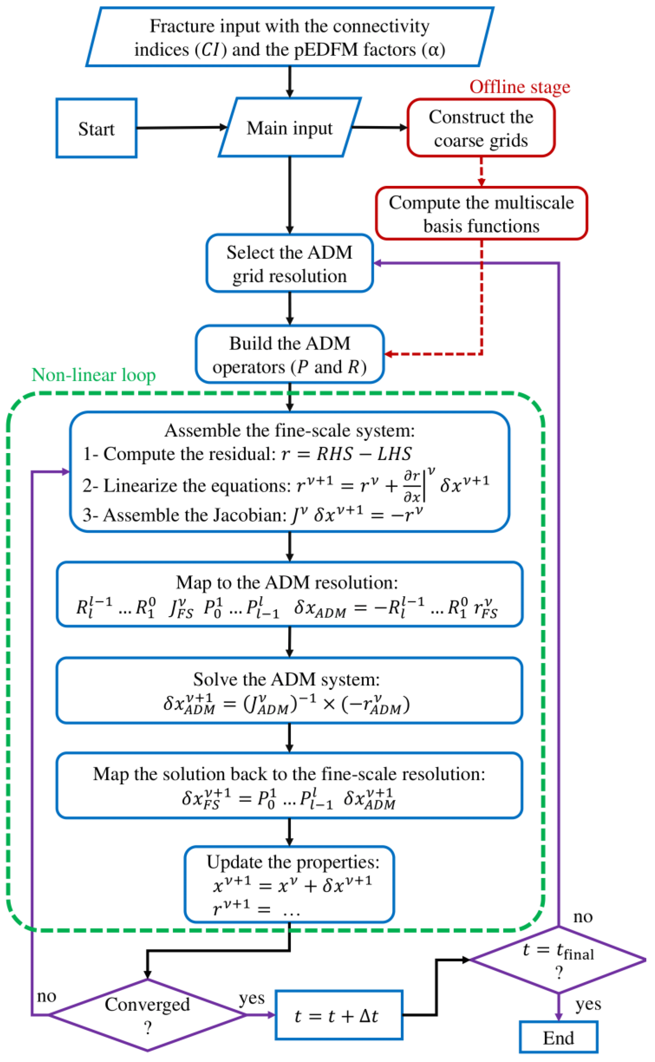
After obtaining the linearized system at fine-scale resolution, the computed residual and Jacobian are given as the input for the ADM method. At each Newton’s iteration step, the fine-scale system is reduced to a multilevel resolution system using ADM restriction ( R ) and prolongation ( P ) operators. The converted ADM system is given by
R ^ l l 1 R ^ 1 0 J 0 P 0 1 P l 1 l δ x l = R ^ l l 1 R ^ 1 0 r 0 .
Here, R ^ l l 1 denotes the restriction operator mapping part of the solution vector at resolution l 1 δ x l 1 to a coarser resolution l δ x l . The term P l 1 l refers to the prolongation operator which maps part of the solution vector at level l to a finer level l 1 . The next step is to solve the system at ADM resolution. The approximated solution at the fine-scale resolution δ x 0 (the exact fine-scale solution as reference is denoted as δ x 0 ) is computed as
δ x 0 δ x 0 = P 0 1 P l 1 l δ x l .
The ADM prolongation and restriction operators between every two levels are assembled from the static multilevel multiscale operators, which are computed only at the beginning of the simulation. The multilevel multiscale prolongation operator P l 1 l is structured as
P l 1 l = P x 1 l 1 l m , m P x 1 l 1 l m , f 0 0 P x 1 l 1 l f , m P x 1 l 1 l f , f 0 0 0 0 P x 2 l 1 l m , m 0 0 0 0 P x 2 l 1 l m , m N l 1 × N l ,
and the restriction operator is given by
R l l 1 = R l l 1 m 0 0 0 0 R l l 1 f 0 0 0 0 R l l 1 m 0 0 0 0 R l l 1 f N l × N l 1 .
To ensure mass conservation, a finite volume restriction operator is used:
R l l 1 s , t = 1 ,   if   finer   cell   s   inside   coarser   cell   t , 0 ,   otherwise .
Note that the blocks of the prolongation operator for different unknowns ( x 1 refers to pressure p , and x 2 refers to either temperature T or the total enthalpy H depending on the formulation), i.e., P x 1 l 1 l and P x 2 l 1 l , are treated differently due to different nature of the unknowns [28]. In this work P x 2 l 1 l = R l l 1 T , where the superscript T denotes the transpose operator. Figure 2 illustrates the workflow for the proposed ADM strategy.
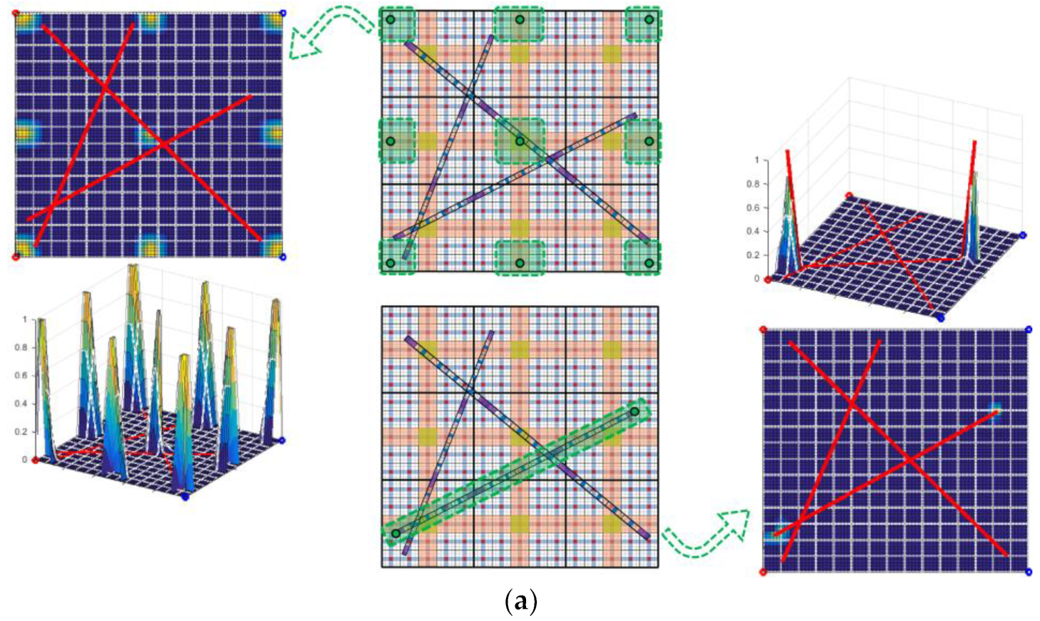
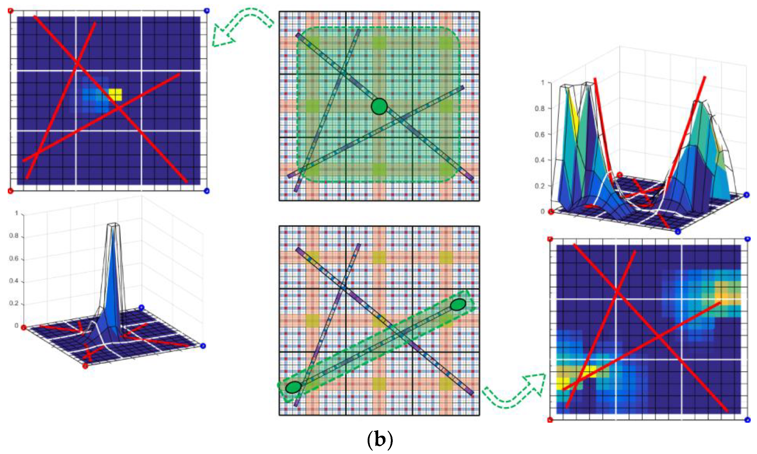
The prolongation operator, which includes the basis functions at different coarsening levels, is constructed in an algebraic manner [39]. To compute the basis functions, the fine-scale system is assembled first. Next, coarse grids are imposed on the fine-scale domain. For example, we consider a 2D domain with 75 × 75 fine-scale matrix grids and three fractures. The coarsening ratio for the matrix and the fracture is given by γ m l = 5 × 5 and γ f l = 5 , respectively. Instances of a few basis functions for the above-mentioned domain in two coarsening levels are visualized in Figure 3.

3. Results and Discussions

In this section, the ADM method for fractured geothermal reservoirs is studied using two test cases. In the first test, a comparison between the results of the simulations for the molar and the natural formulations is presented. In the second part, through a 3D fractured test case, the performance of the ADM method is demonstrated for the high-enthalpy multi-phase flow with the implementation of the molar formulation.

3.1. Comparison between Natural Formulation and Molar Formulation

Here, a comparison is made between the natural and the molar formulation for single-phase flow in low-enthalpy geothermal systems. Figure 4 shows a schematic overview of the production strategy and fracture geometry in a 2D domain of 100 [m] × 100 [m]. Two injection/production wells are placed on the left/right corners of the domain, respectively. The domain consists of 30 mix-conductive fractures. Table 1 shows the physical parameters and simulation settings used in the test case. The initial reservoir temperature, rock matrix properties, and permeability field are chosen such that the test case represents the geothermal fields of Middenmeer in the Netherlands. The geothermal fluid is assumed to be pure water. The computation of fluid properties is presented in Appendix A.
To compare the results between the two formulations, a formulation error is introduced to quantify the relative difference between the numerical solutions obtained from both formulations. The formulation error is calculated as
e f = x p H x p T 2 x p T 2 ,
where x p H 2 and x p T 2 are the L 2 -norms of a given variable x using the molar and natural formulation, respectively. Note that the result obtained from the natural formulation is used as a reference solution.
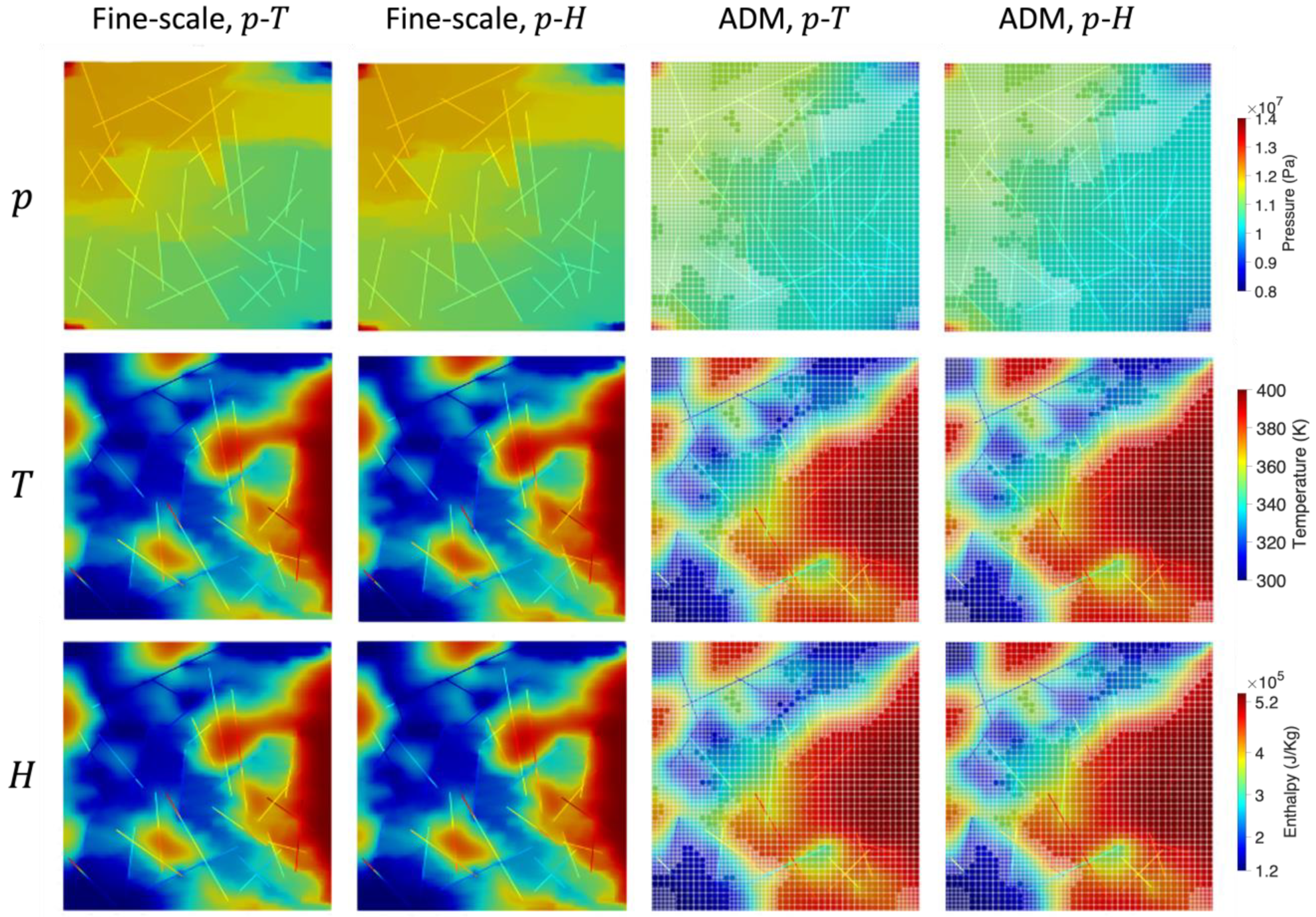
Figure 5 shows the results of multiple runs with both formulations on fine-scale and ADM. As shown, the maps obtained from the two formulations exhibit similar behavior for both simulation strategies. In cases of ADM, fine-scale grids are employed in the vicinity of the displacement front so that the dynamics of flow are captured accurately, and coarser grids are used in regions away from the front to improve computational efficiency. We also observe that the temperature inside the impermeable fractures is higher than that in the highly conductive ones. This is because heat convection is hindered by the flow barriers. The time-lapsed formulation error is presented in Figure 6. Among the three investigated properties, enthalpy and temperature have relatively larger errors compared to the pressure. This is because local variables, i.e., enthalpy and temperature, evolve along with the transport of the cold water through the reservoir, and consequently, they are more sensitive to the grid resolution (levels of coarsening). Nevertheless, the maximum relative error is approximately 3%, which indicates that the difference in performance between both formulations is insignificant.

3.2. High-Enthalpy System Using Molar Formulation

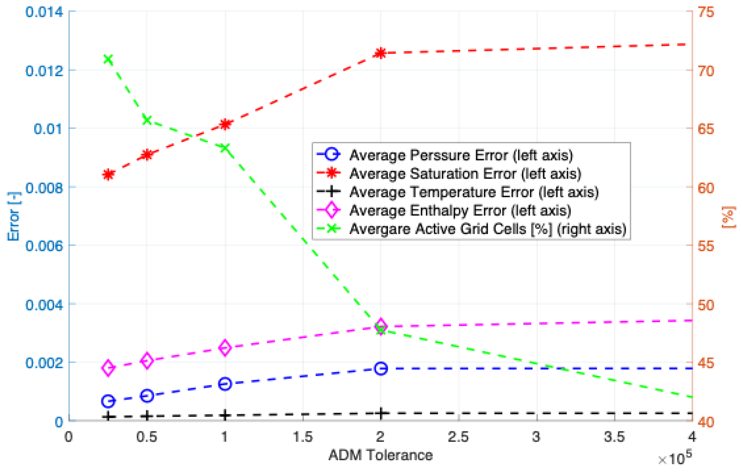
In this subsection, the ADM method is assessed for multiphase flow in high-enthalpy fractured geothermal reservoirs using the molar formulation. The ADM results on different ADM grid resolution selection tolerances of Δ H = 0.25 , 0.5 , 1.0 , 2.0 , 4.0 × 10 5 [J/Kg] are compared against the fine-scale results as a reference solution. The ADM error is calculated as
e x = x FS x ADM 2 x FS 2 ,
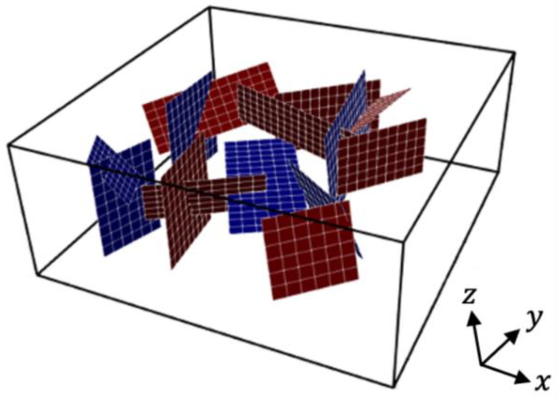
with x being a solution vector of either of the primary variables. Table 2 lists the input parameters that are used in this multiphase flow test case. A 3D domain of 100 [m] × 100 [m] × 40 [m] with 15 fractures is considered. The matrix has homogeneous permeability of 1.0 × 10⁻¹⁴ [m2], whereas the fractures have mixed conductivity with the permeability of 1.0 × 10⁻⁸ [m2] for highly conductive fractures and 1.0 × 10⁻²⁰ [m2] for the impermeable ones. Figure 7 illustrates the geometry of the fracture network with different colors highlighting their differences in conductivities. Well configuration is similar to the previous test case shown in Figure 4.
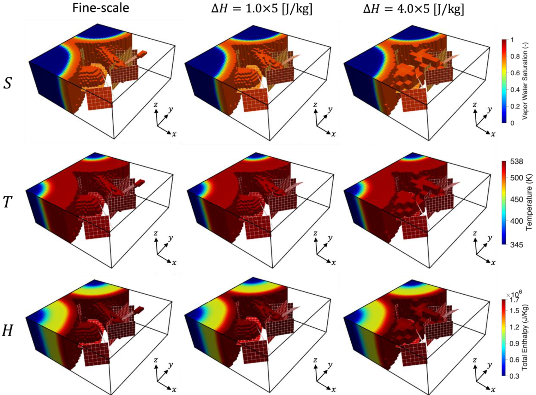
Figure 8 shows the simulation results for fine-scale and the ADM with grid resolution selection tolerance of Δ H = 1.0 , 4.0 × 10 5 [J/Kg]. In the ADM runs, two coarsening levels are used with the coarsening ratio of γ = 3 at each dimension. These results are at simulation time t = 28 [days]. Saturation of vapor water, temperature, and the total fluid enthalpy distribution at the mentioned simulation time are presented. Unlike the single-phase flow test in which the temperature and the total enthalpy maps exhibit comparable distribution, here the front of total enthalpy propagates further compared to that of the temperature. Due to a highly diffusive front, more fine-scale grids are used at the front depending on the tolerance.
More details regarding the errors and the percentage of the active grid cells used in the simulation are presented in Figure 9. Note that the percentage of active grid cells refers to the ratio of the number of grid cells used to solve the linearized system in the ADM over that of the fine-scale. As the ADM tolerance increases, fewer active grids are used thereby improving the computational efficiency. On the other hand, the error increases especially for saturation, whereas for temperature, the error is relatively insensitive to the changes in ADM tolerance.
Simulation results from these two test cases indicate that the molar formulation is a better option in terms of implementation, as the pressure and the total enthalpy stay independent regardless of thermodynamic conditions. In addition, the error for saturation is in general greater than that for pressure and temperature. This implies that one can devise more accurate multilevel basis functions for saturation as the next step.

4. Conclusions

An algebraic dynamic multilevel (ADM) method for coupled mass–heat multiphase flow in fractured geothermal reservoirs under varying thermodynamic conditions is presented. The pEDFM model is used to account for fractures with varying conductivities in an explicit manner. The non-linear mass and energy balance equations are coupled using the fully implicit method, and the resulting fine-scale system is mapped to a discrete domain with dynamic grid resolution via the use of restriction and prolongation operators. These operators are assembled from the static multiscale basis functions, which are calculated only at the beginning of the simulation. Matrix–fracture interactions are incorporated in the multiscale basis functions. Main findings are summarized as follows.
  • Numerical results indicate that the two formulations with different primary variables, i.e., natural formulation ( p - T ) and molar formulation ( p - H ), produce similar results in the case of single-phase flow. In the case studied, the maximum formulation error for the fine-scale and the ADM simulation are 1.9 and 3.0%, respectively.
  • The performance of ADM is evaluated by comparing the simulation results with those obtained from the fine-scale grids. We observe that the ADM method provides computational efficiency by reducing the size of the linear system, while keeping the accuracy at a user-defined level. In the case with the highest tolerance, only 42% of grid cells are active, and the maximum error is 1.3% from the saturation map.
Because of its algebraic framework, the ADM method can be applied to large-scale fractured geothermal reservoirs for scalable simulation of coupled mass–heat processes.

Author Contributions

Conceptualization, M.H. and H.H.; methodology, Y.W., M.H., A.M. and H.H.; software, Y.W., M.H. and A.M.; investigation, Y.W., M.H. and A.M.; writing—original draft preparation, Y.W., A.M. and M.H.; writing—review and editing, H.H.; supervision, H.H.; project administration, H.H.; funding acquisition, Y.W. and H.H. All authors have read and agreed to the published version of the manuscript.

Funding

Yuhang Wang was supported by the “CUG Scholar” Scientific Research Funds at China University of Geosciences (Wuhan) (Project No. 2022157). Hadi Hajibeygi was sponsored by the Dutch National Science Foundation (NWO) under Vidi Talent Program Project “ADMIRE” (Project No. 17509).

Data Availability Statement

Data are available on request from the corresponding authors.

Conflicts of Interest

The authors declare no conflict of interest.

Appendix A

Thermodynamic properties of pure water and steam are expressed depending on primary variables. The natural formulation uses correlations developed by [30], and the molar formulation employs correlations developed by [41]. All variables are presented in SI units.

Appendix A.1. Natural Formulation

The density of the liquid phase is treated as a function of pressure and temperature given by
ρ l p , T = ρ l , s T 1 + c f T p p sat ,
where the saturation pressure p sat has a constant value of 105 [Pa]. ρ l , s T and c f T are obtained from empirical correlations:
ρ l , s T = 0.0032 T 2 + 1.7508 T + 757.5 ,
c f T = 0.0839 T 2 + 652.73 T 203714 × 10 12 .
The liquid phase enthalpy is treated as a function of pressure and temperature given by
h l p , T = U l , s + C p , l T T sat + p ρ l ,
where T sat is the saturation temperature with a constant value of 373 [K]; U l , s = 420,000 [J/Kg] and C p , l = 4200 [J/Kg/K].
The viscosity of the liquid phase is treated as a function of temperature expressed by
μ l T = 2.414 × 10 5 × 10 247.8 T 140 .

Appendix A.2. Molar Formulation

The liquid and vapor phase densities are treated as functions of pressure and enthalpy given by
ρ l p , H = 1.00207 + 4.42607 × 10 11 p 5.47456 × 10 12 H + 5.02875 × 10 21 p H 1.24791 × 10 21 H 2 × 10 3 ,
ρ v p , H = 2.26162 × 10 5 + 4.38441 × 10 9 p 1.79088 × 10 19 p H + 3.69276 × 10 36 p 4 + 5.17644 × 10 41 p H 3 × 10 3 .
The saturated liquid and vapor phase enthalpies are functions of pressure given by
h l p = 7.30984 × 10 9 + 1.29239 × 10 2 p 1.00333 × 10 6 p 2 + 3.9881 × 10 15 p 3 9.90697 × 10 15 p 1 + 1.29267 × 10 22 p 2 6.28359 × 10 27 p 3 × 10 7 ,
h v p = 2.82282 × 10 10 3.91952 × 10 5 p 1 + 2.54342 × 10 21 p 2 9.38879 × 10 8 p 2 × 10 7 .
The temperature in the compressed water region is given by
T p , H = 273.15 2.41231 + 2.5622 × 10 8 H 9.31415 × 10 17 p 2 2.2568 × 10 19 H 2 ,
and in the superheated stream region by
T p , H = 273.15 374.669 + 4.79921 × 10 6 p 6.33606 × 10 15 p 2 + 7.39386 × 10 19 H 2 3.3372 × 10 34 H 2 p 2 + 3.57154 × 10 19 p 3 1.1725 × 10 37 H 3 p 2.26861 × 10 43 H 4 .
Note that in the two-phase region, the saturated liquid phase enthalpy is used in the equation instead.
The liquid and vapor phase viscosities are computed as functions of temperature:
μ l T = 2.414 × 10 5 × 10 247.8 T 140 ,
μ v T = 0.407 × T 273.15 + 80.4 × 10 4 .

References

  1. Lund, J.W. Direct utilization of geothermal energy. Energies 2010, 3, 1443–1471. [Google Scholar] [CrossRef]
  2. Bertani, R. Geothermal power generation in the world 2005–2010 update report. Geothermics 2012, 41, 1–29. [Google Scholar] [CrossRef]
  3. Lund, J.W.; Boyd, T.L. Direct utilization of geothermal energy 2015 worldwide review. Geothermics 2016, 60, 66–93. [Google Scholar] [CrossRef]
  4. Gan, Q.; Elsworth, D. Production optimization in fractured geothermal reservoirs by coupled discrete fracture network modeling. Geothermics 2016, 62, 131–142. [Google Scholar] [CrossRef] [Green Version]
  5. Gholizadeh Doonechaly, N.; Abdel Azim, R.R.; Rahman, S.S. A study of permeability changes due to cold fluid circulation in fractured geothermal reservoirs. Groundwater 2016, 54, 325–335. [Google Scholar] [CrossRef] [PubMed]
  6. Ijeje, J.J.; Gan, Q.; Cai, J. Influence of permeability anisotropy on heat transfer and permeability evolution in geothermal reservoir. Adv. Geo-Energy Res. 2019, 3, 43–51. [Google Scholar] [CrossRef]
  7. Wang, Y.; de Hoop, S.; Voskov, D.; Bruhn, D.; Bertotti, G. Modeling of multiphase mass and heat transfer in fractured high-enthalpy geothermal systems with advanced discrete fracture methodology. Adv. Water Resour. 2021, 154, 103985. [Google Scholar] [CrossRef]
  8. Mahmoodpour, S.; Singh, M.; Turan, A.; Bär, K.; Sass, I. Simulations and global sensitivity analysis of the thermo-hydraulic-mechanical processes in a fractured geothermal reservoir. Energy 2022, 247, 123511. [Google Scholar] [CrossRef]
  9. Mahmoodpour, S.; Singh, M.; Bär, K.; Sass, I. Thermo-hydro-mechanical modeling of an enhanced geothermal system in a fractured reservoir using carbon dioxide as heat transmission fluid—A sensitivity investigation. Energy 2022, 254, 124266. [Google Scholar] [CrossRef]
  10. Khait, M.; Voskov, D. Operator-based linearization for efficient modeling of geothermal processes. Geothermics 2018, 74, 7–18. [Google Scholar] [CrossRef]
  11. Wong, Z.Y.; Horne, R.N.; Tchelepi, H.A. Sequential implicit nonlinear solver for geothermal simulation. J. Comput. Phys. 2018, 368, 236–253. [Google Scholar] [CrossRef]
  12. Pruess, K.; Oldenburg, C.M.; Moridis, G. TOUGH2 User’s Guide Version 2; Technical Report LBNL-43134; Lawrence Berkeley National Laboratory: Berkeley, CA, USA, 1999.
  13. Pruess, K. Numerical simulation of multiphase tracer transport in fractured geothermal reservoirs. Geothermics 2002, 31, 475–499. [Google Scholar] [CrossRef]
  14. Garipov, T.T.; Tomin, P.; Rin, R.; Voskov, D.V.; Tchelepi, H.A. Unified thermo-compositional-mechanical framework for reservoir simulation. Comput. Geosci. 2018, 22, 1039–1057. [Google Scholar] [CrossRef]
  15. Wong, Z.Y.; Horne, R.; Voskov, D. Comparison of nonlinear formulations for geothermal reservoir simulations. In Proceedings of the 41st Workshop on Geothermal Reservoir Engineering, Stanford, CA, USA, 22–24 February 2016. [Google Scholar]
  16. Hou, T.Y.; Wu, X.H. A multiscale finite element method for elliptic problems in composite materials and porous media. J. Comput. Phys. 1997, 134, 169–189. [Google Scholar] [CrossRef] [Green Version]
  17. Jenny, P.; Lee, S.H.; Tchelepi, H.A. Multi-scale finite-volume method for elliptic problems in subsurface flow simulation. J. Comput. Phys. 2003, 187, 47–67. [Google Scholar] [CrossRef]
  18. Jenny, P.; Lee, S.H.; Tchelepi, H.A. Adaptive fully implicit multi-scale finite-volume method for multi-phase flow and transport in heterogeneous porous media. J. Comput. Phys. 2006, 217, 627–641. [Google Scholar] [CrossRef]
  19. Hajibeygi, H.; Bonfigli, G.; Hesse, M.A.; Jenny, P. Iterative multiscale finite-volume method. J. Comput. Phys. 2008, 227, 8604–8621. [Google Scholar] [CrossRef]
  20. Wang, Y.; Hajibeygi, H.; Tchelepi, H.A. Algebraic multiscale solver for flow in heterogeneous porous media. J. Comput. Phys. 2014, 259, 284–303. [Google Scholar] [CrossRef]
  21. Edwards, M.G. A higher-order Godunov scheme coupled with dynamic local grid refinement for flow in a porous medium. Comput. Methods Appl. Mech. Eng. 1996, 131, 287–308. [Google Scholar] [CrossRef]
  22. Pau, G.S.; Almgren, A.S.; Bell, J.B.; Lijewski, M.J. A parallel second-order adaptive mesh algorithm for incompressible flow in porous media. Philos. Trans. R. Soc. Lond. Ser. A 2009, 367, 4633–4654. [Google Scholar] [CrossRef]
  23. Faigle, B.; Helmig, R.; Aavatsmark, I.; Flemisch, B. Efficient multiphysics modelling with adaptive grid refinement using a MPFA method. Comput. Geosci. 2014, 18, 625–636. [Google Scholar] [CrossRef]
  24. Adam, A.; Pavlidis, D.; Percival, J.R.; Salinas, P.; Xie, Z.; Fang, F.; Pain, C.C.; Muggeridge, A.H.; Jackson, M.D. Higher-order conservative interpolation between control-volume meshes: Application to advection and multiphase flow problems with dynamic mesh adaptivity. J. Comput. Phys. 2016, 321, 512–531. [Google Scholar] [CrossRef] [Green Version]
  25. Karimi-Fard, M.; Durlofsky, L.J. A general gridding, discretization, and coarsening methodology for modeling flow in porous formations with discrete geological features. Adv. Water Resour. 2016, 96, 354–372. [Google Scholar] [CrossRef]
  26. Wang, Y.; Shahvali, M. Discrete fracture modeling using Centroidal Voronoi grid for simulation of shale gas plays with coupled nonlinear physics. Fuel 2016, 163, 65–73. [Google Scholar] [CrossRef]
  27. Künze, R.; Lunati, I.; Lee, S.H. A multilevel multiscale finite-volume method. J. Comput. Phys. 2013, 255, 502–520. [Google Scholar] [CrossRef]
  28. Cusini, M.; van Kruijsdijk, C.; Hajibeygi, H. Algebraic dynamic multilevel (ADM) method for fully implicit simulations of multiphase flow in porous media. J. Comput. Phys. 2016, 314, 60–79. [Google Scholar] [CrossRef]
  29. HosseiniMehr, M.; Cusini, M.; Vuik, C.; Hajibeygi, H. Algebraic dynamic multilevel method for embedded discrete fracture model (F-ADM). J. Comput. Phys. 2018, 373, 324–345. [Google Scholar] [CrossRef] [Green Version]
  30. Coats, K.H. Geothermal reservoir modelling. In Proceedings of the SPE Annual Fall Technical Conference and Exhibition, Denver, CO, USA, 9–12 October 1977. [Google Scholar]
  31. Gelet, R.; Loret, B.; Khalili, N. The significance of local thermal non-equilibrium in simulations of enhanced geothermal recovery. In Proceedings of the 14th International Conference of the International Association for Computer Methods and Advances in Geomechanics (IACMAG), Kyoto, Japan, 22–25 September 2014. [Google Scholar]
  32. Nag, P.K. Engineering Thermodynamics, 6th ed.; McGraw Hill: New York, NY, USA, 2017. [Google Scholar]
  33. Faust, C.R.; Mercer, J.W. Geothermal reservoir simulation: 1. Mathematical models for liquid-and vapor-dominated hydrothermal systems. Water Resour. Res. 1979, 15, 23–30. [Google Scholar] [CrossRef]
  34. Jiang, J.; Younis, R.M. Hybrid coupled discrete-fracture/matrix and multicontinuum models for unconventional-reservoir simulation. SPE J. 2016, 21, 1009–1027. [Google Scholar] [CrossRef]
  35. Flemisch, B.; Berre, I.; Boon, W.; Fumagalli, A.; Schwenck, N.; Scotti, A.; Stefansson, I.; Tatomir, A. Benchmarks for single-phase flow in fractured porous media. Adv. Water Resour. 2018, 111, 239–258. [Google Scholar] [CrossRef]
  36. Ţene, M.; Bosma, S.B.; Al Kobaisi, M.S.; Hajibeygi, H. Projection-based embedded discrete fracture model (pEDFM). Adv. Water Resour. 2017, 105, 205–216. [Google Scholar] [CrossRef]
  37. HosseiniMehr, M.; Tomala, J.P.; Vuik, C.; Al Kobaisi, M.; Hajibeygi, H. Projection-based embedded discrete fracture model (pEDFM) for flow and heat transfer in real-field geological formations with hexahedral corner-point grids. Adv. Water Resour. 2022, 159, 104091. [Google Scholar] [CrossRef]
  38. Wang, Y.; Vuik, C.; Hajibeygi, H. CO2 Storage in deep saline aquifers: Impacts of fractures on hydrodynamic trapping. Int. J. Greenh. Gas Control 2022, 113, 103552. [Google Scholar] [CrossRef]
  39. Ţene, M.; Al Kobaisi, M.S.; Hajibeygi, H. Algebraic multiscale method for flow in heterogeneous porous media with embedded discrete fractures (F-AMS). J. Comput. Phys. 2016, 321, 819–845. [Google Scholar] [CrossRef]
  40. Wagner, W.; Kretzschmar, H.J. International Steam Tables: Properties of Water and Steam Based on the Industrial Formulation IAPWS-IF97, 3rd ed.; Springer: Berlin/Heidelberg, Germany, 2017. [Google Scholar]
  41. Faust, C.R.; Mercer, J.W. Finite-Difference Model of Two Dimensional, Single-, and Two-Phase Heat Transport in a Porous Medium: Version I; US Department of the Interior, Geological Survey: Washington, DC, USA, 1977. [Google Scholar]
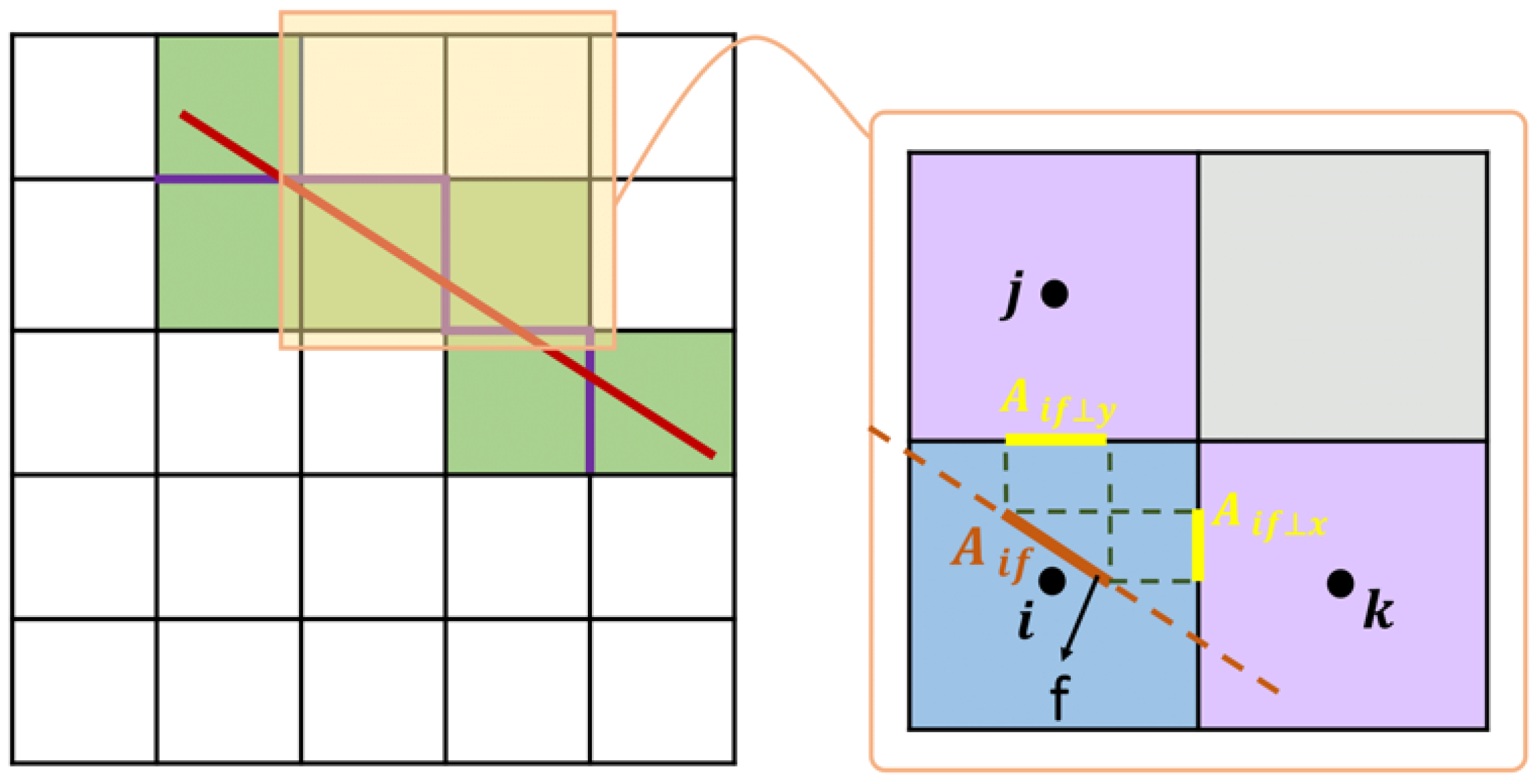
Figure 1. Schematic of pEDFM for a 2D domain with a 1D fracture.
Energies 16 00928 g001
Figure 2. Workflow for the ADM strategy.
Energies 16 00928 g002
Figure 3. Visualization of some basis functions for (a) coarsening level 1, and (b) coarsening level 2 for a 2D domain with 75 × 75 fine-scale matrix grids and three 1D fracture each with 75 grids.
Energies 16 00928 g003aEnergies 16 00928 g003b
Figure 4. Schematic of the (a) production strategy and (b) fracture geometry applied in the single-phase test case. The highly conductive fractures are shown in red color and the impermeable ones are colored in blue.
Energies 16 00928 g004
Figure 5. The pressure (top row), temperature (middle row), and the total enthalpy (bottom row) of the fine-scale and ADM simulations, both for the natural and the molar formulation.
Energies 16 00928 g005
Figure 6. The formulation error for (a) fine-scale, and (b) ADM simulations.
Energies 16 00928 g006
Figure 7. Schematic of fracture geometry applied in the multiphase test case. The highly conductive fractures are shown in red color and the impermeable ones are colored in blue.
Energies 16 00928 g007
Figure 8. Fine-scale and ADM results from the tolerances of Δ H = 1.0 , 4.0 × 10 5 [J/Kg]. Starting from the top row to the bottom row, the results of saturation, temperature, and total enthalpy are presented. Note that for better visualization, only a portion of grids in the solutions are visible.
Energies 16 00928 g008
Figure 9. ADM errors and the percentage of the active cells used for each ADM run. The error for each parameter as well as the percentage of the active cells for each ADM run are averaged over the entire simulation.
Energies 16 00928 g009
Table 1. Input parameters used in the single-phase flow test case.
PropertyValue
Porosity0.2
Rock density2600 [Kg/m3]
Rock specific heat capacity830 [J/Kg/K]
Rock thermal conductivity2.9 [W/m/K]
Fracture permeability{1.0 × 10⁻⁸, 1.0 × 10⁻²⁰} [m2]
Fracture aperture5.0 × 10−3 [m]
Fracture porosity1.0
Initial temperature400 [K]
Initial pressure1.0 × 107 [Pa]
Injection temperature300 [K]
Injection pressure1.4 × 107 [Pa]
Production pressure0.8 × 107 [Pa]
Simulation time2000 [days]
Tolerance for convergence1.0 × 10−4 [-]
ADM coarsening levels2
ADM coarsening ratio3 × 3
Table 2. Input parameters used in the multiphase flow test case. Thermodynamic properties for water of liquid and vapor phase are referred to [40].
PropertyValue
Porosity0.2
Rock permeability1.0 × 10−14 [m2]
Rock compressibility1.0 × 10−8 [1/Pa]
Rock density2600 [Kg/m3]
Rock specific heat capacity850 [J/Kg/K]
Rock thermal conductivity3.0 [W/m/K]
Fracture permeability{1.0 × 10⁻⁸, 1.0 × 10⁻²⁰} [m2]
Fracture aperture5.0 × 10−3 [m]
Fracture porosity1.0
Initial enthalpy1.6 × 106 [J/Kg]
Initial pressure5.0 × 106 [Pa]
Water liquid compressibility1.0 × 10−9 [1/Pa]
Water vapor compressibility1.0 × 10−6 [1/Pa]
Water liquid specific heat capacity4200 [J/Kg/K]
Water vapor specific heat capacity8000 [J/Kg/K]
Water liquid thermal conductivity0.6 [W/m/K]
Water vapor thermal conductivity0.1 [W/m/K]
Injection enthalpy3.0 × 105 [J/Kg]
Injection pressure6.0 × 106 [Pa]
Production pressure4.0 × 106 [Pa]
Simulation time200 [days]
Disclaimer/Publisher’s Note: The statements, opinions and data contained in all publications are solely those of the individual author(s) and contributor(s) and not of MDPI and/or the editor(s). MDPI and/or the editor(s) disclaim responsibility for any injury to people or property resulting from any ideas, methods, instructions or products referred to in the content.