
Steady-State Vibration Level Measurement of the Five-Phase Induction Machine during Third Harmonic Injection or Open-Phase Faults


Abstract
1. Introduction
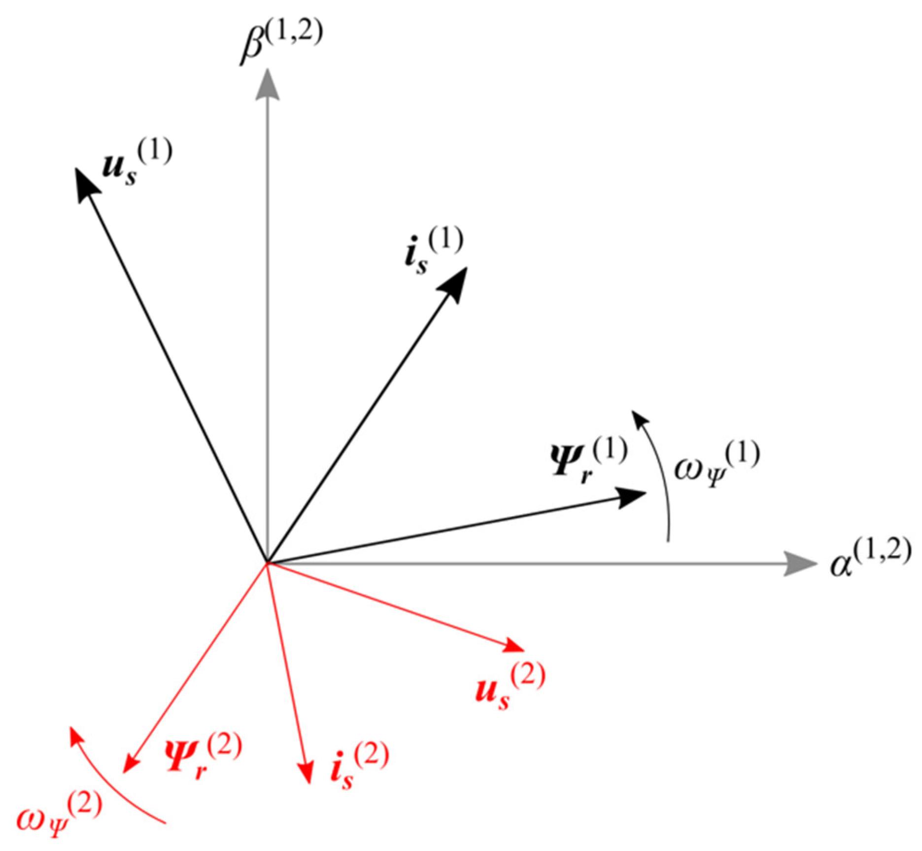
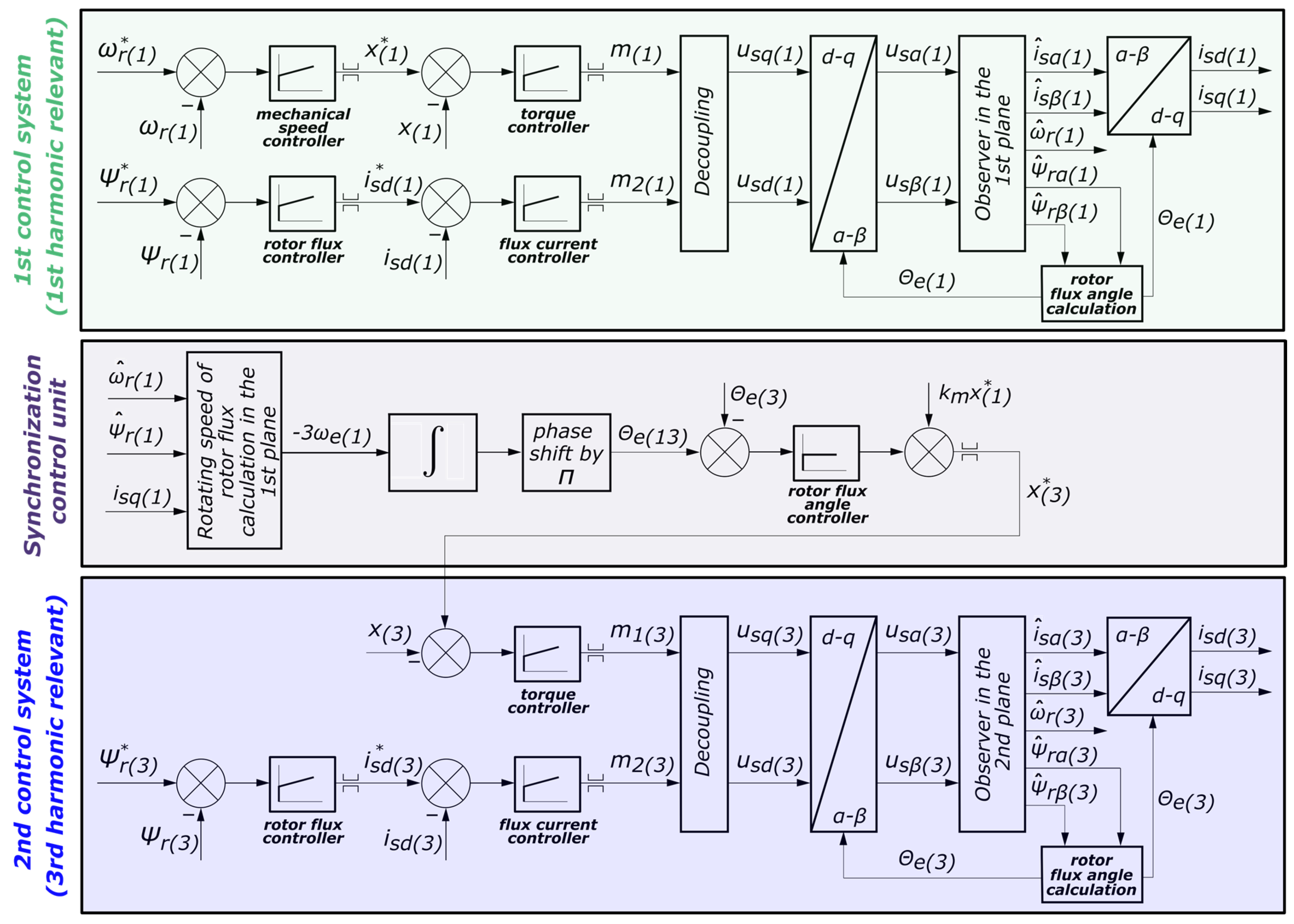
2. Selected Strategy for Sensorless Control of a 5-Phase Motor
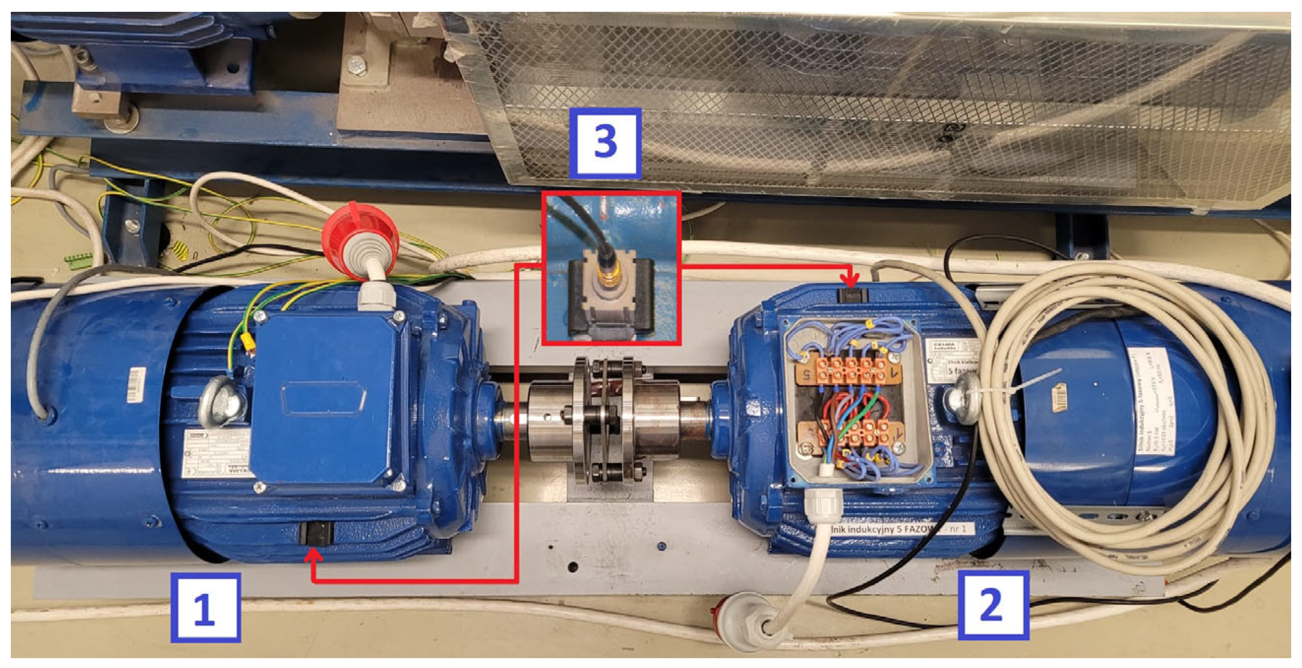
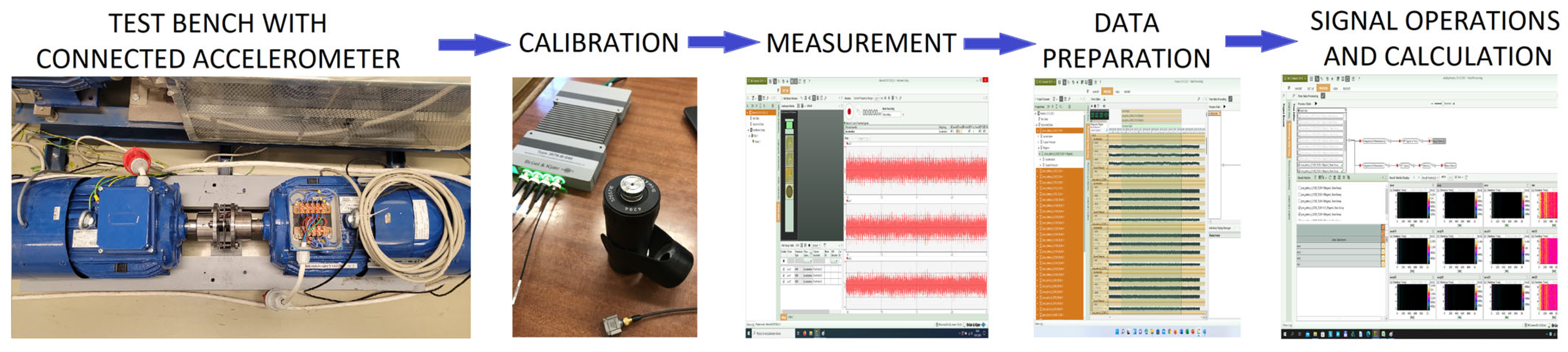
3. Laboratory Stand and Measurement Methods
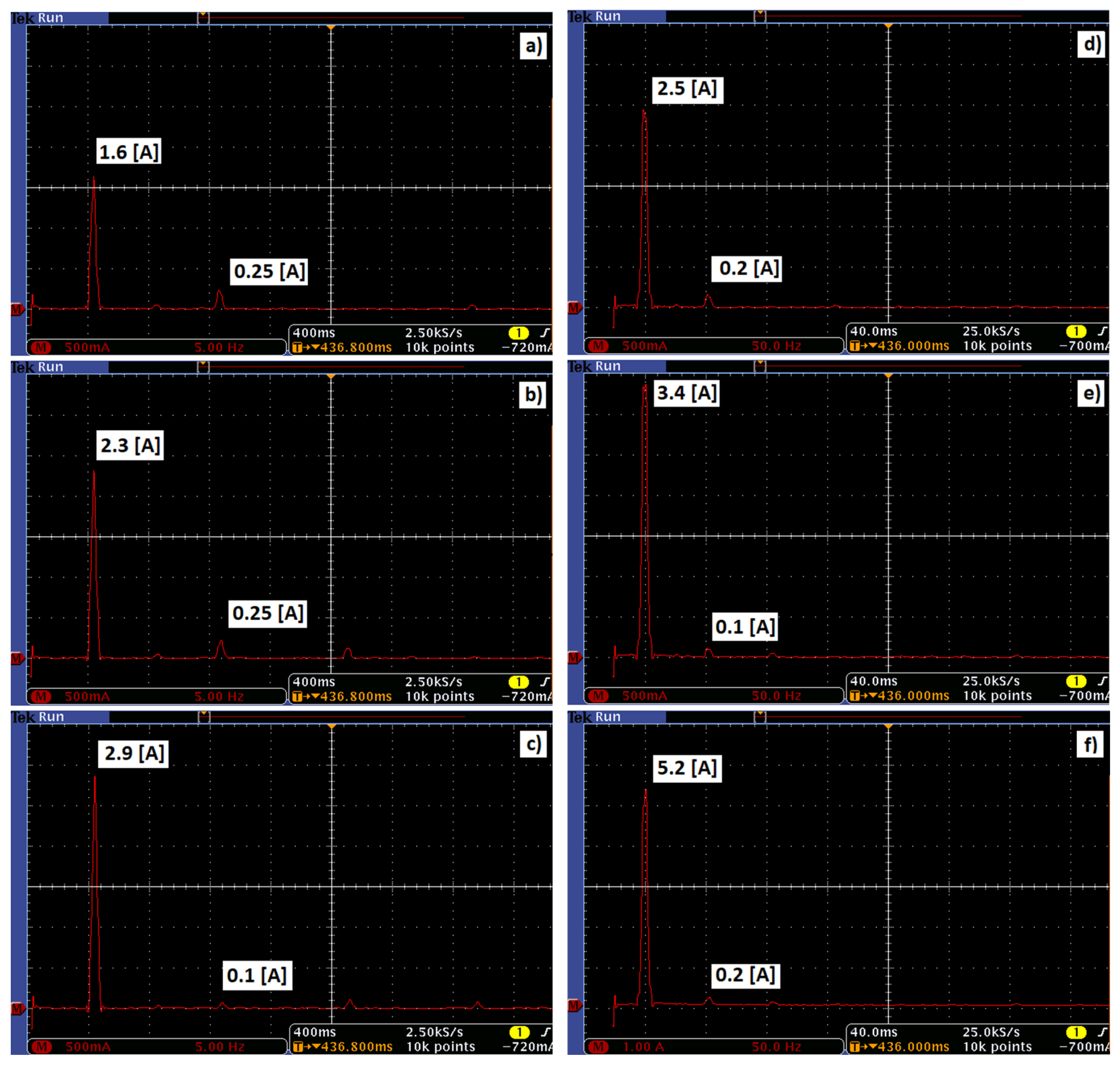
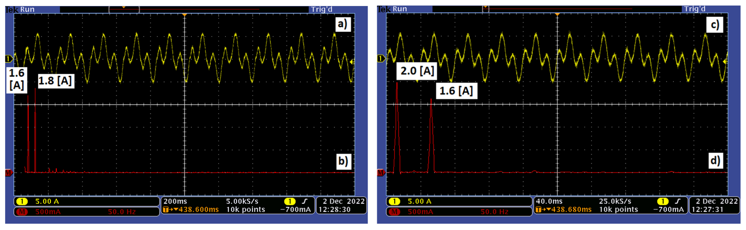
4. Analysis of Results from Electrical Measurements
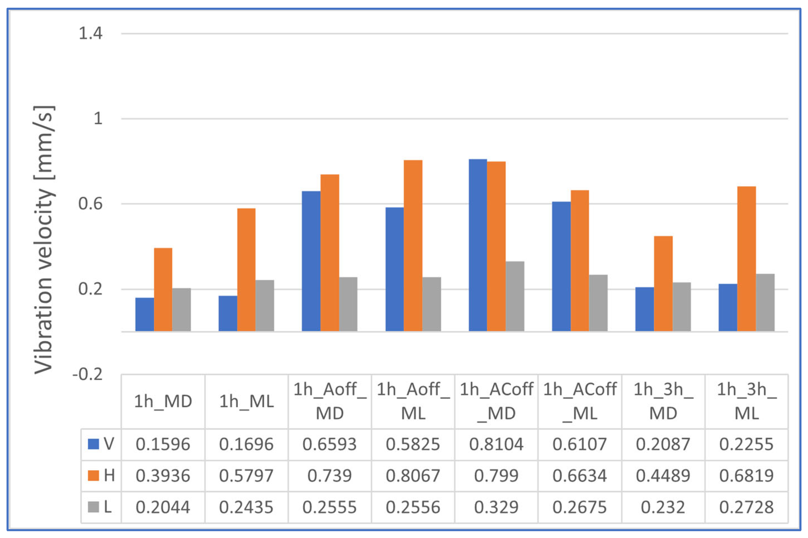
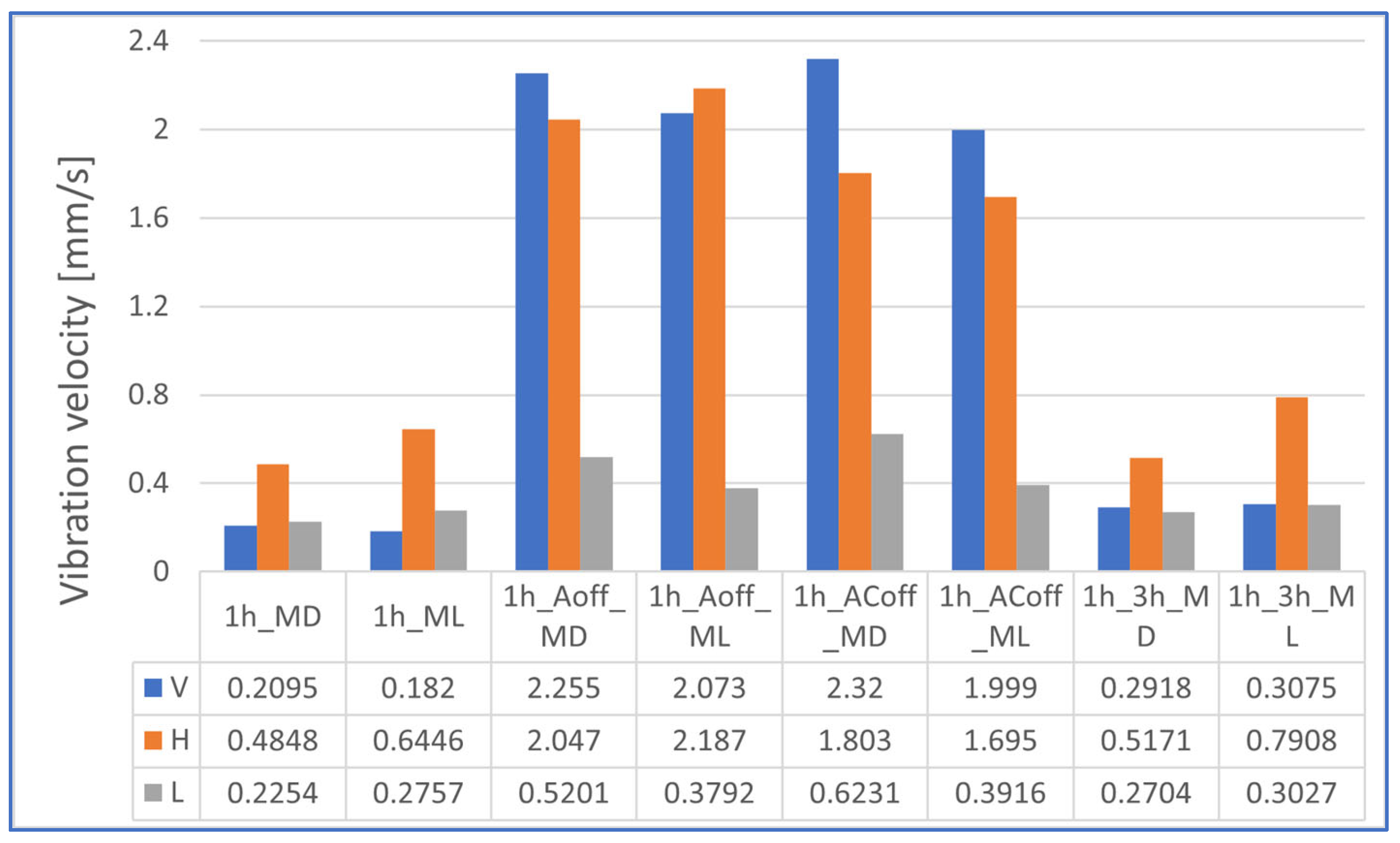
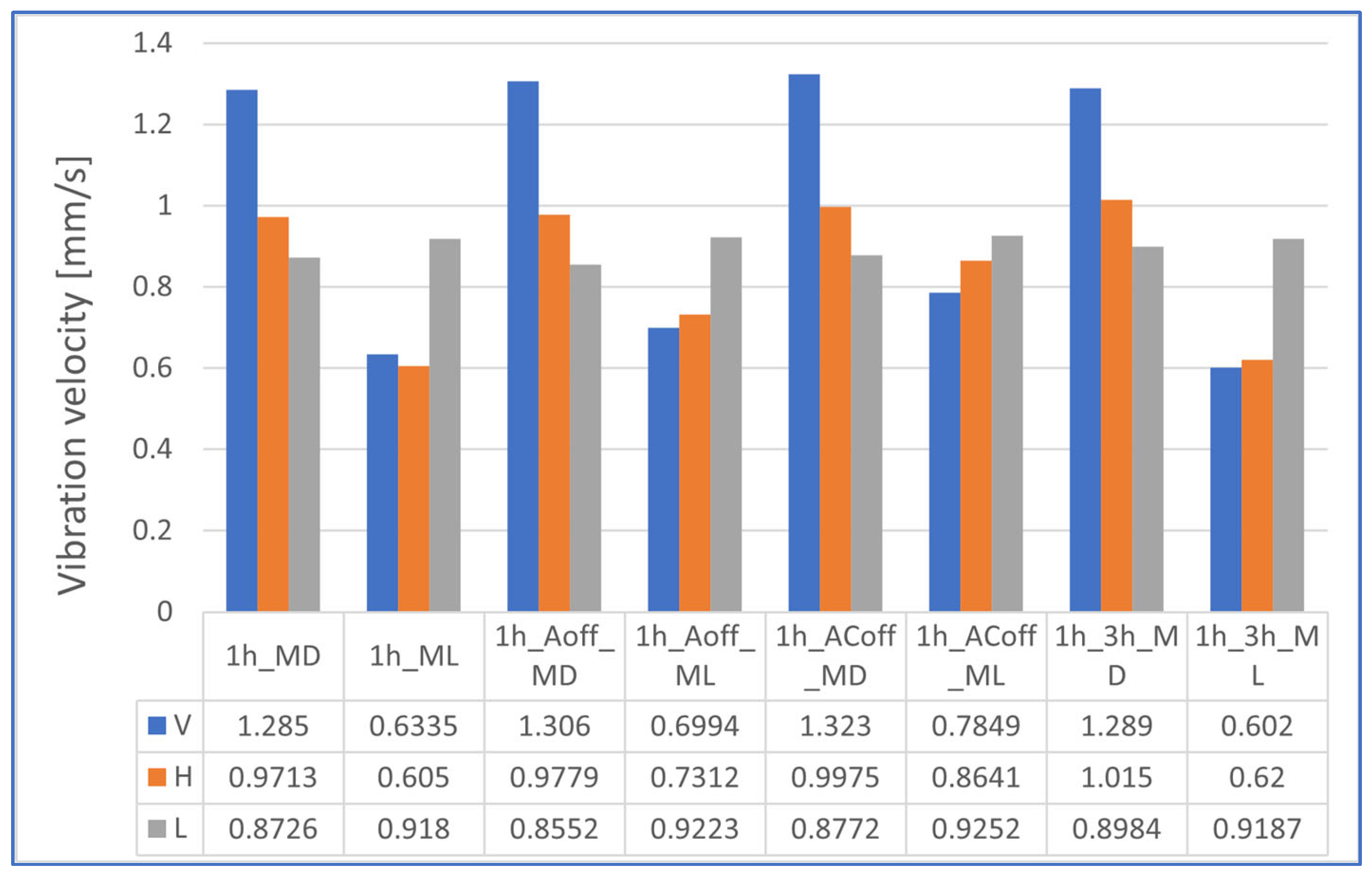
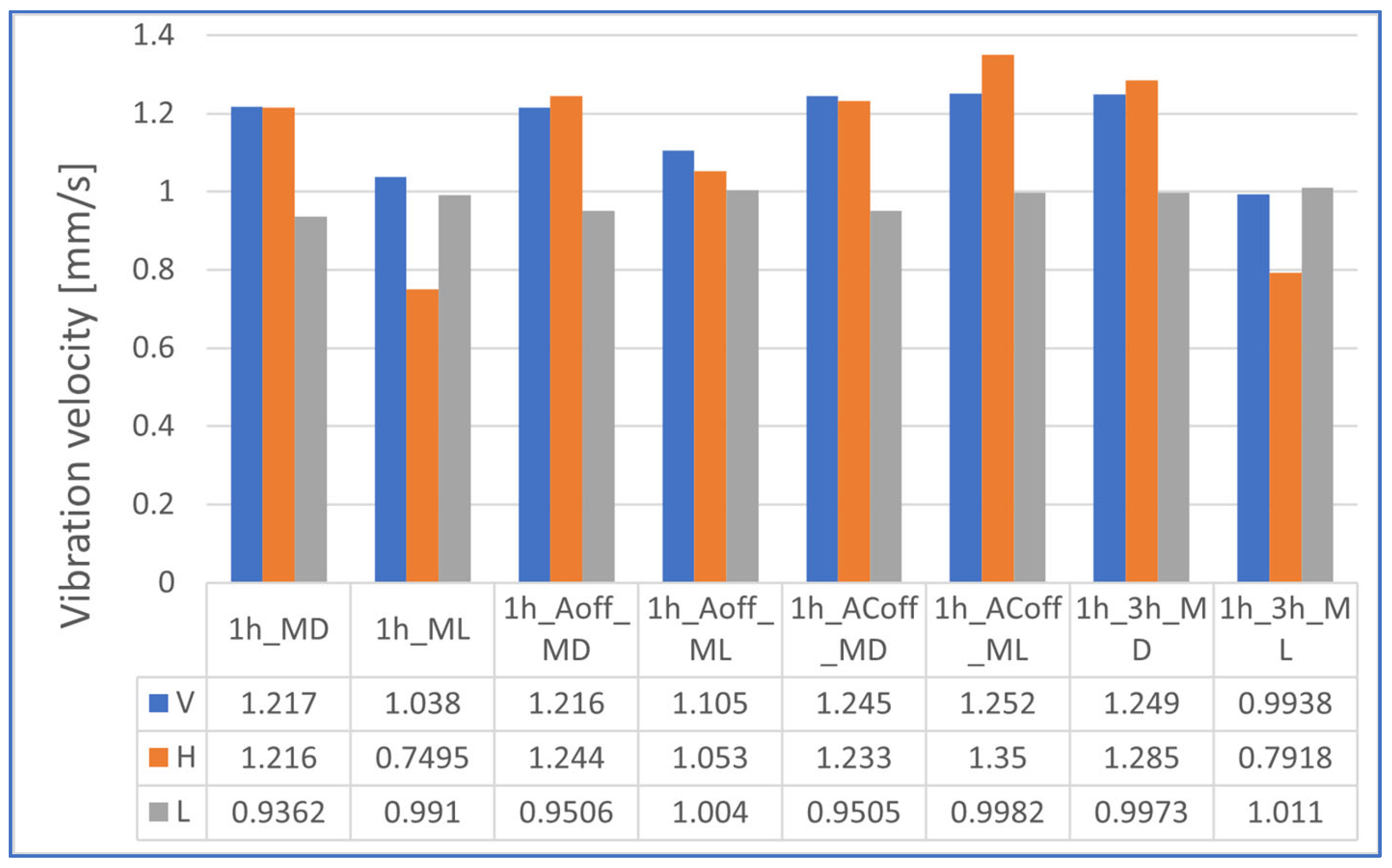
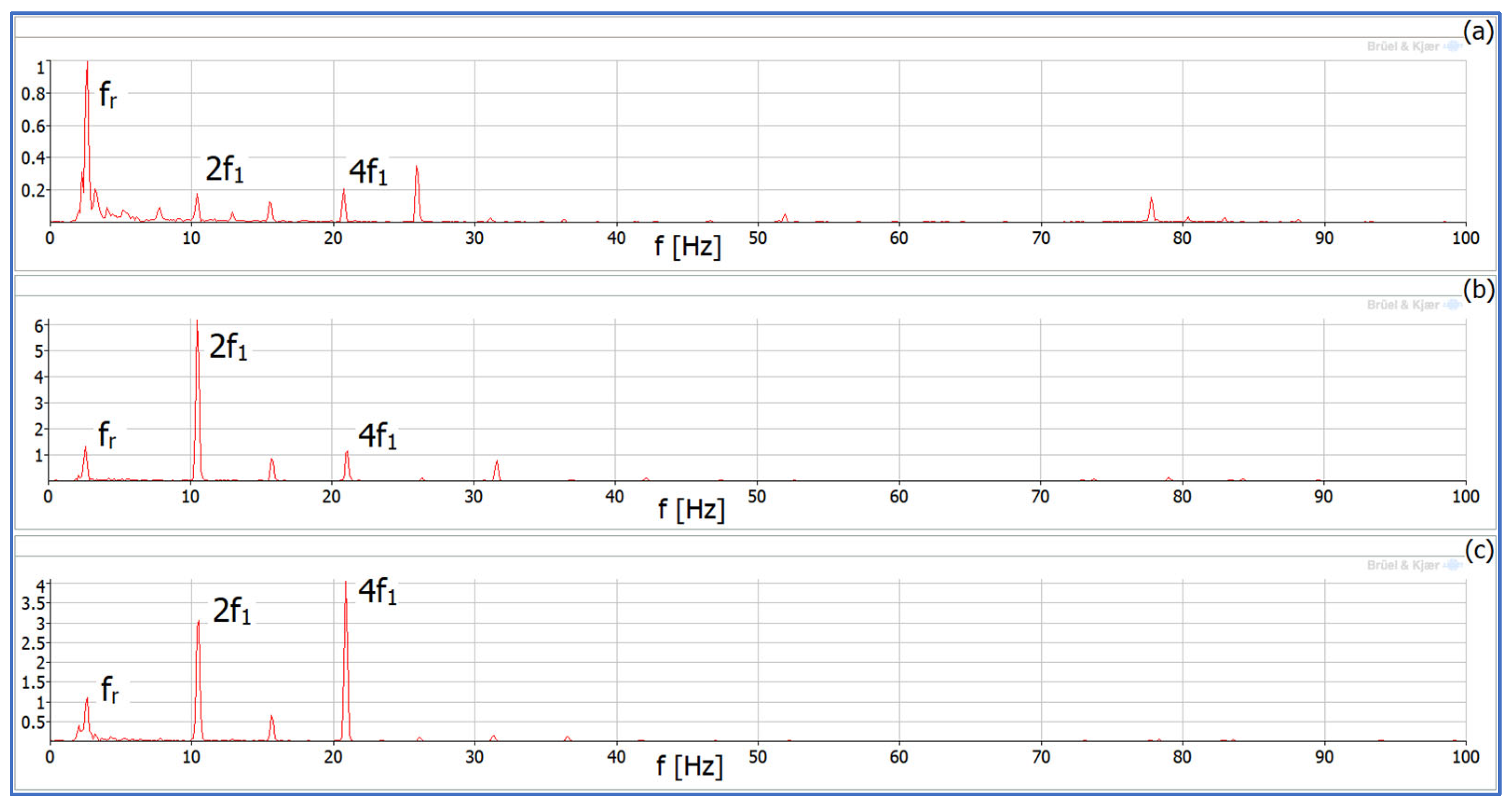
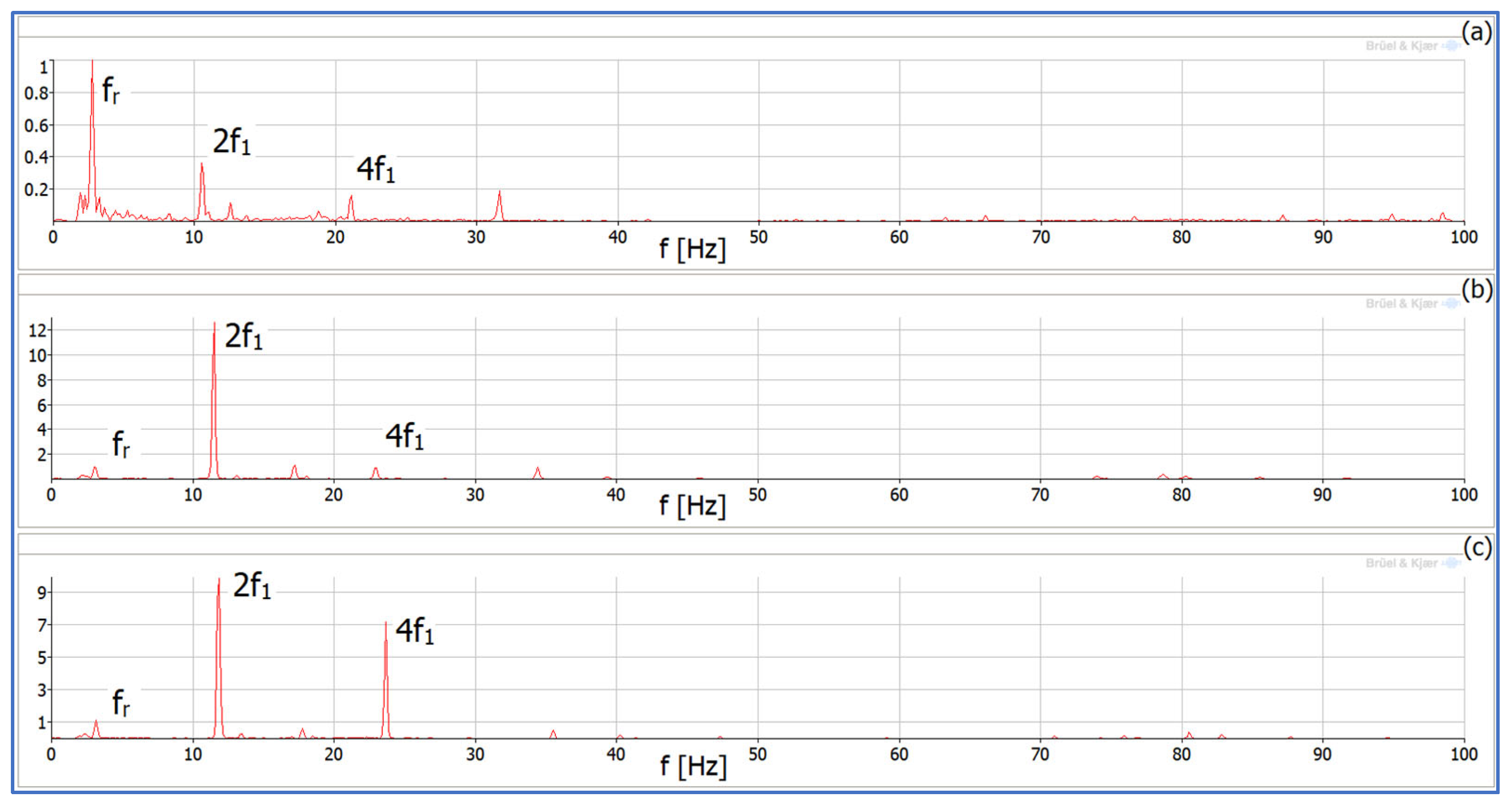
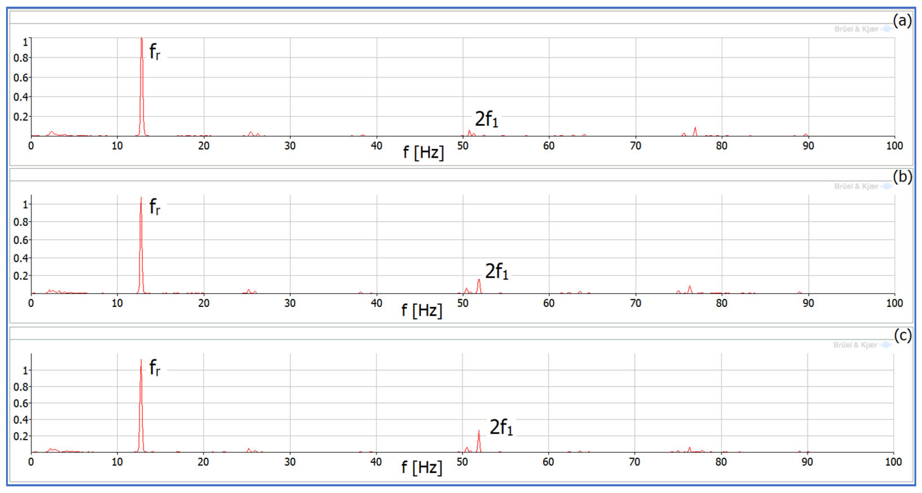
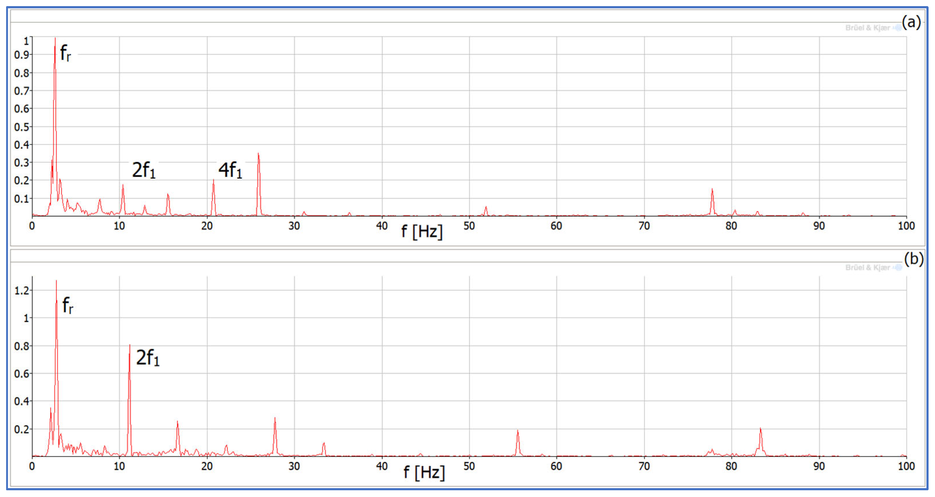
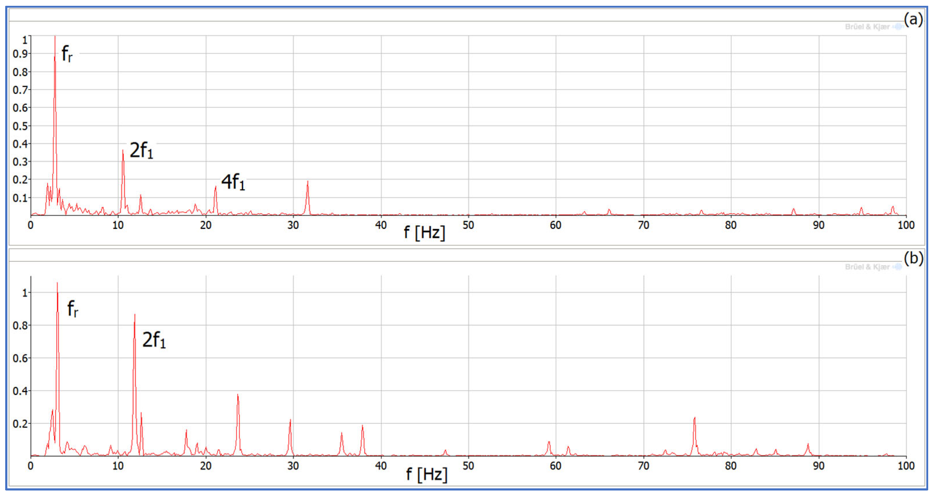
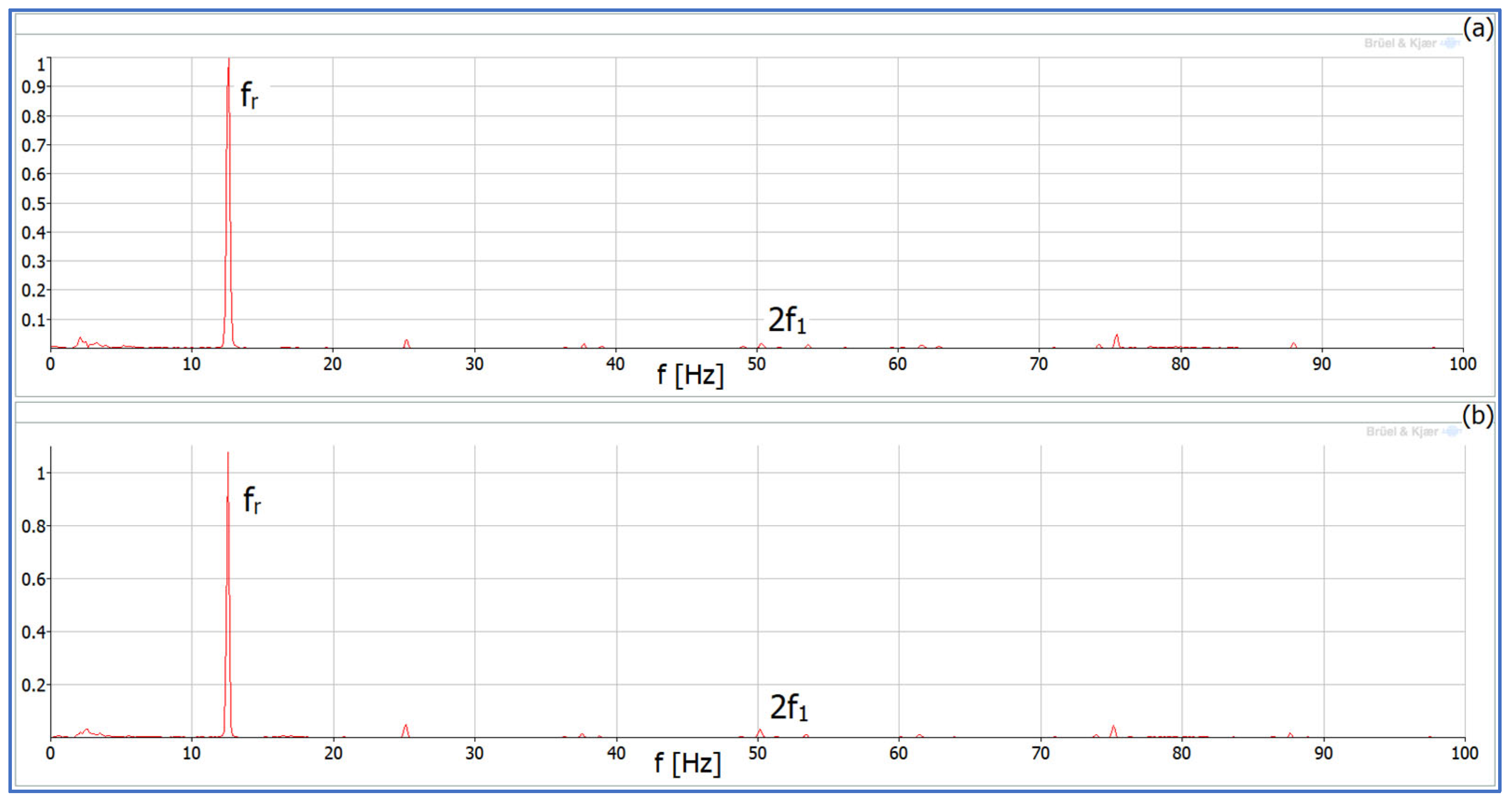
5. Analysis of Results from Vibrodiagnostic Measurements
- MD—measurement of vibrations on the drive motor;
- ML—measurement of vibrations on the load motor;
- 1 h—supply of the first harmonic;
- 1 h_3 h—1st and 3rd harmonic power supply;
- Aoff—power supply without phase A;
- ACoff—power supply without phases A and C.
- -
- 10% of nominal rotor speed—150 rpm;
- -
- 50% of nominal rotor speed—750 rpm;
- -
- 50% of nominal load torque;
- -
- All machine phases are turned on (health condition);
- -
- Phases A and/or C are turned off (fault condition).
6. Conclusions
Author Contributions
Funding
Data Availability Statement
Conflicts of Interest
References
- Lee, S.S.; Bak, Y.; Kim, S.-M.; Joseph, A.; Lee, K.-B. New Family of Boost Switched-Capacitor Seven-Level Inverters (BSC7LI). IEEE Trans. Power Electron. 2019, 34, 10471–10479. [Google Scholar] [CrossRef]
- Ramirez, H.; Restrepo, C.; Konjedic, T.; Calvente, J.; Romero, A.; Baier, C.; Giral, R. An efficiency comparison of fuel-cell hybrid systems based on the versatile buck–boost converter. IEEE Trans. Power Electron. 2017, 33, 1237–1246. [Google Scholar] [CrossRef]
- Gorecki, K.; Detka, K. Analysis of influence of losses in the core of the inductor on parameters of the buck converter. In Proceedings of the 2018 Baltic URSI Symposium (URSI), Poznan, Poland, 14–17 May 2018; pp. 129–132. [Google Scholar] [CrossRef]
- Siddique, M.D.; Mekhilef, S.; Shah, N.M.; Sarwar, A.; Iqbal, A.; Tayyab, M.; Ansari, M.K. Low Switching Frequency Based on Asymmetrical Multilevel Inverter Topology with Reduced Switch Count. IEEE Access 2019, 7, 86374–86383. [Google Scholar] [CrossRef]
- Muc, A.; Iwaszkiewicz, J. Active Filtering of Inverter Output Waveforms Based on Orthogonal Space Vector Theory. Energies 2022, 15, 7861. [Google Scholar] [CrossRef]
- Tsypkin, M. Induction motor condition monitoring: Vibration analysis technique—diagnosis of electromagnetic anomalies. In Proceedings of the 2017 IEEE AUTOTESTCON, Schaumburg, IL, USA, 9–15 September 2017; pp. 1–7. [Google Scholar] [CrossRef]
- Tsypkin, M. The origin of the electromagnetic vibration of induction motors operating in modern industry: Practical experience—Analysis and diagnostics. IEEE Trans. Ind. Appl. 2016, 53, 1669–1676. [Google Scholar] [CrossRef]
- Gnaciński, P.; Hallmann, D.; Muc, A.; Klimczak, P.; Pepliński, M. Induction Motor Supplied with Voltage Containing Symmetrical Subharmonics and Interharmonics. Energies 2022, 15, 7712. [Google Scholar] [CrossRef]
- Kabul, A.; Unsal, A. A Diagnosis Method of Multiple Faults of Induction Motors Based on Vibration Signal Analysis. In Proceedings of the 2021 IEEE 13th International Symposium on Diagnostics for Electrical Machines, Power Electronics and Drives (SDEMPED), Dallas, TX, USA, 22–25 August 2021; Volume 1, pp. 415–421. [Google Scholar] [CrossRef]
- Ayala, J.; Meira, M.; Verucchi, C.; Bossio, G.; Acosta, G. Combined Vibration and Stator Current Techniques for Induction Motors Fault Detection–A Review. In Proceedings of the 2021 XIX Workshop on Information Processing and Control (RPIC), San Juan, Argentina, 3–5 November 2021; pp. 1–6. [Google Scholar] [CrossRef]
- Saravanan, M.; Rajini, G.K. Vibration Analysis of Electrical Machine. In Proceedings of the 2021 Innovations in Power and Advanced Computing Technologies (i-PACT), Kuala Lumpur, Malaysia, 27–29 November 2021; pp. 1–6. [Google Scholar] [CrossRef]
- Iwaszkiewicz, J.; Muc, A. State and Space Vectors of the 5-Phase 2-Level VSI. Energies 2020, 13, 4385. [Google Scholar] [CrossRef]
- Iwaszkiewicz, J.; Muc, A.; Bielecka, A. Polar Voltage Space Vectors of the Six-Phase Two-Level VSI. Energies 2022, 15, 2763. [Google Scholar] [CrossRef]
- Wu, J.; Xu, Q.; Xu, L. A Study on Winding MMF Harmonic and Vibration of Polyphase Motor. In Proceedings of the 2021 Power System and Green Energy Conference (PSGEC), Shanghai, China, 13–16 May 2021; pp. 732–737. [Google Scholar] [CrossRef]
- Wilczyński, F.; Strankowski, P.; Guziński, J.; Morawiec, M.; Lewicki, A. Sensorless field oriented control for five-phase induction motors with third harmonic injection and fault insensitive feature. Bull. Pol. Acad. Sci. Tech. Sci. 2019, 67, 253–262. [Google Scholar] [CrossRef]
- Luu, P.T.; Lee, J.; Jeong, Y.; Kim, J.; Lee, J.; Lee, K. Investigation of Multi-Physical Characteristics in Coupling-Five-Phase Motor under Driver-Open-Phase Fault Condition for Small Propulsion System. In Proceedings of the 2019 22nd International Conference on Electrical Machines and Systems (ICEMS), Harbin, China, 11–14 August 2019; pp. 1–4. [Google Scholar] [CrossRef]
- Lanciotti, N.; Ojeda, J.; Gabsi, M.; Boukhobza, T. Open-phase fault detection using vibrations in five-phase flux switching machine. In Proceedings of the 2017 18th International Symposium on Electromagnetic Fields in Mechatronics, Electrical and Electronic Engineering (ISEF) Book of Abstracts, Lodz, Poland, 14–16 September 2017; pp. 1–2. [Google Scholar] [CrossRef]
- Lewicki, A.; Odeh, C.I.; Kondratenko, D.; Morawiec, M. Hybridized Space-Vector Pulsewidth Modulation for Multiphase Two-Level Voltage Source Inverter. IEEE Trans. Power Electron. 2022, 37, 7663–7674. [Google Scholar] [CrossRef]
- Scuiller, F. Third harmonic current injection to reduce the pulsating torque of a five-phase SPM machine. In Proceedings of the IECON 2015-41st Annual Conference of the IEEE Industrial Electronics Society, Yokohama, Japan, 9–12 November 2015; pp. 000811–000816. [Google Scholar] [CrossRef]
- Buja, G.; Casadei, D.; Serra, G. Direct torque control of induction motor drives. In ISIE ‘97 Proceedings of the IEEE International Symposium on Industrial Electronics, Guimaraes, Protugal, 7–11 July 1997; IEEE: New York, NY, USA; Volume 1, pp. TU2–TU8. [CrossRef]
- Adamowicz, M.; Guzinski, J.; Krzeminski, Z. Nonlinear control of five phase induction motor with synchronized third harmonic flux injection. In Proceedings of the 2015 First Workshop on Smart Grid and Renewable Energy (SGRE), Doha, Qatar, 22–23 March 2015; pp. 1–6. [Google Scholar]
- Adamowicz, M.; Krzeminski, Z.; Morawiec, M.; Strankowski, P.; Guziński, J. Multiscalar control of five phase induction motor. Electr. Rev. 2016, 1, 108–115. [Google Scholar]
- Gnacinski, P.; Muc, A.; Peplinski, M. Influence of Voltage Subharmonics on Line Start Permanent Magnet Synchronous Motor. IEEE Access 2021, 9, 164275–164281. [Google Scholar] [CrossRef]
- IEC Standard IEC61000-4-7; Electromagnetic Compatibility (EMC)—Part 4–7: Testing and Measurement Techniques—General Guide on Harmonics and Interharmonics Measurements and Instrumentation, for Power Supply Systems and Equipment Connected Thereto. International Electrotechnical Commission: Geneva, Switzerland, 2002.
- ISO Standard 20816-1; Mechanical Vibration—Measurement and Evaluation of Machine Vibration—Part 1: General Guide-lines. ISO: Geneva, Switzerland, 2016.
- ISO Standard 10816-1; Mechanical Vibration—Evaluation of Machine Vibration by Measurements on Non-Rotating Parts—Part 1: General Guidelines. ISO: Geneva, Switzerland, 1995.
- Tani, A.; Mengoni, M.; Zarri, L.; Serra, G.; Casadei, D. Control of Multiphase Induction Motors with an Odd Number of Phases Under Open-Circuit Phase Faults. IEEE Trans. Power Electron. 2011, 27, 565–577. [Google Scholar] [CrossRef]
- Strankowski, P.; Guzinski, J.; Morawiec, M.; Lewicki, A.; Wilczynski, F. Sensorless disturbance detection for five phase induction motor with third harmonic injection. In Proceedings of the 2017 11th IEEE International Conference on Compatibility, Power Electronics and Power Engineering (CPE-POWERENG), Cadiz, Spain, 4–6 April 2017; pp. 387–391. [Google Scholar] [CrossRef]
- Strankowski, P.; Jaderko, A.; Blecharz, K.; Morawiec, M. Fault Detection Algorithm for Five-Phase Induction Motor Drive. In Proceedings of the 2019 Applications of Electromagnetics in Modern Engineering and Medicine (PTZE), Podlaski, Poland, 9–12 June 2019; pp. 215–218. [Google Scholar] [CrossRef]
- Xu, X.; Han, Q.; Chu, F. Review of Electromagnetic Vibration in Electrical Machines. Energies 2018, 11, 1779. [Google Scholar] [CrossRef]
- Hennen, M.D.; Niessen, M.; Heyers, C.; Brauer, H.J.; De Doncker, R.W. Development and Control of an Integrated and Distributed Inverter for a Fault Tolerant Five-Phase Switched Reluctance Traction Drive. IEEE Trans. Power Electron. 2011, 27, 547–554. [Google Scholar] [CrossRef]
- Glose, D.; Qian, P.; Kennel, R. Efficiency and Vibration Observations of a Symmetrical Six-Phase Drive applying Interleaved Space Vector Modulation. In Proceedings of the PCIM Europe 2016; International Exhibition and Conference for Power Electronics, Intelligent Motion, Renewable Energy and Energy Management, Nuremberg, Germany, 10–12 May 2016; pp. 1–8. [Google Scholar]
- Ding, A.; Huang, C.; Sun, Z.; Zeng, R.; Mao, Y.; Jia, G.; Luo, H.; Xu, J. Six-phase cylindrical linear induction motor with high-frequency vibration suppression and experimental study. In Proceedings of the 2022 IEEE 5th International Electrical and Energy Conference (CIEEC), Nanjing, China, 27–29 May 2022; pp. 1976–1981. [Google Scholar] [CrossRef]
- Smith, A.C.; Dorrell, D.G. Calculation and measurement of magnetic pull in cage induction with eccentric rotors. Part 1: Analytical model. IEEE Proc. Electr. Power Appl. 1996, 143, 193–201. [Google Scholar] [CrossRef]
- Nandi, S.; Bharadwaj, R.M.; Toliyat, H.A. Mixed eccentricity in three phase induction machines: Analysis, simulation and experiments. In Proceedings of the 2002 IEEE Industry Applications Conference—37th IAS Annual Meeting (Cat. No. 02CH37344), Pittsburgh, PA, USA, 13–18 October 2002; pp. 1525–1532. [Google Scholar]
- Xing, Z.; Wang, X.; Zhao, W.; Wang, F. Calculation of Stator Natural Frequencies of Electrical Machines Considering Complex Boundary Conditions. IEEE Trans. Ind. Appl. 2022, 58, 7079–7087. [Google Scholar] [CrossRef]
- Ojeda, J.; Boisson, J.; Gabsi, M. 5-phase flux switching machine insulation failure detection using vibration monitoring. In Proceedings of the 2014 17th International Conference on Electrical Machines and Systems (ICEMS), Hangzhou, China, 22–25 October 2014; pp. 1039–1043. [Google Scholar] [CrossRef]


| Parameters | Fife-Phase Drive Motor | Three-Phase Load Motor |
|---|---|---|
| Rated output power | 5.5 kW | 5.5 kW |
| Rated current | 8.8 A | 11 A |
| Rated phase voltage | 173 V | 230 V |
| Number of poles | 4 | 2 |
| Rated torque | 36.5 Nm | 36.5 Nm |
| Rated speed | 1440 rpm | 1440 rpm |
| Transistor switching frequency | 3.3 kHz | 3.3 kHz |
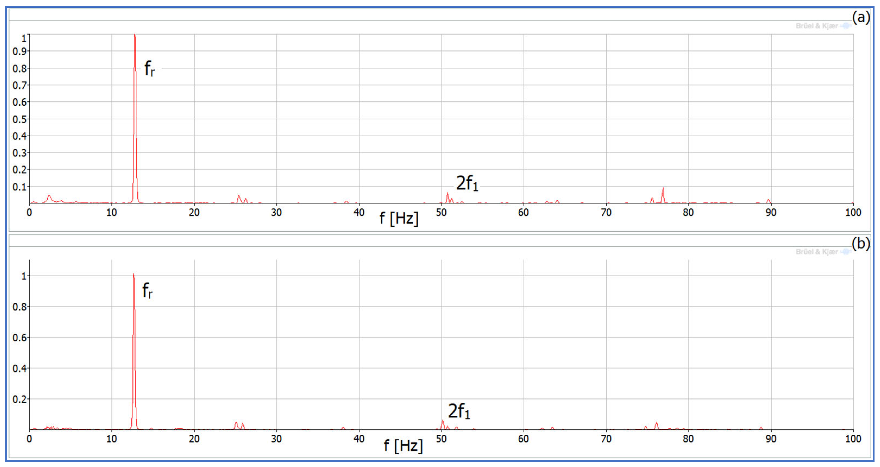
| Motor Speed | 150 rpm | 750 rpm |
|---|---|---|
| fr | 2.5 Hz | 12.5 Hz |
| f1 = 2fr | 5.0 Hz | 25.0 Hz |
| 2f1 = 4fr | 10.0 Hz | 50.0 Hz |
| 3f1 = 6fr | 15.0 Hz | 75.0 Hz |
| 4f1 = 6fr | 20.0 Hz | 100.0 Hz |
| … | … | … |
Disclaimer/Publisher’s Note: The statements, opinions and data contained in all publications are solely those of the individual author(s) and contributor(s) and not of MDPI and/or the editor(s). MDPI and/or the editor(s) disclaim responsibility for any injury to people or property resulting from any ideas, methods, instructions or products referred to in the content. |
© 2023 by the authors. Licensee MDPI, Basel, Switzerland. This article is an open access article distributed under the terms and conditions of the Creative Commons Attribution (CC BY) license (https://creativecommons.org/licenses/by/4.0/).
Share and Cite
Muc, A.; Morawiec, M.; Wilczyński, F. Steady-State Vibration Level Measurement of the Five-Phase Induction Machine during Third Harmonic Injection or Open-Phase Faults. Energies 2023, 16, 838. https://doi.org/10.3390/en16020838
Muc A, Morawiec M, Wilczyński F. Steady-State Vibration Level Measurement of the Five-Phase Induction Machine during Third Harmonic Injection or Open-Phase Faults. Energies. 2023; 16(2):838. https://doi.org/10.3390/en16020838
Chicago/Turabian StyleMuc, Adam, Marcin Morawiec, and Filip Wilczyński. 2023. "Steady-State Vibration Level Measurement of the Five-Phase Induction Machine during Third Harmonic Injection or Open-Phase Faults" Energies 16, no. 2: 838. https://doi.org/10.3390/en16020838
APA StyleMuc, A., Morawiec, M., & Wilczyński, F. (2023). Steady-State Vibration Level Measurement of the Five-Phase Induction Machine during Third Harmonic Injection or Open-Phase Faults. Energies, 16(2), 838. https://doi.org/10.3390/en16020838