Abstract
The usage of batteries and supercapacitors in the field of electric vehicles is becoming increasingly prominent in both research and development. Due to the complementary advantages of the two systems, high energy density, and high power density, a combined battery/supercapacitor system offers potential. To effectively utilise the potential of such a hybrid energy storage system (HESS), one requires an intelligent energy management system (EMS). The EMS is responsible for controlling the electrical power between the battery and the supercapacitor in such a way that the required power can be optimally distributed at all times (currently and in the future). For this purpose, the energy management system utilises information on the driving route and, based on this information, shall calculate a global strategy for the continuous power distribution. The controlled power distribution should take place in real time and be robust against discrepancies so that unpredictable or unreliably predictable events do not significantly influence the functionality. For the implementation of the concept, a rule-based power distribution is implemented in combination with a predictive energy management. Here, the energy management is combined with a rule-based strategy calculation based on data on the route to be driven with a global optimization for the calculation of a route-specific strategy. Depending on the selected objective, the increase in energy efficiency, or lifetime, the operation of the power control is optimised. Due to the functional separation, the continuous power control can operate in real time, while more computational time can be spent on the calculations of the power management strategy, which accordingly does not need to be executed in real time. The results show that by using the presented EMS, especially in combination with a route-specific parameterisation, a significant effect on the energy efficiency and/or battery lifetime can be achieved. The average battery energy consumption can be reduced by up to 9.14% on urban routes. Regarding battery lifetime, the average battery usage can be reduced up to 13.35% and the battery energy losses even up to 62.72%.
1. Introduction
Driven by ever stricter regulations and requirements to comply with emissions caps, automotive manufacturers are increasingly aiming to electrify the vehicles [1]. When promoting fully electric vehicles, car manufacturers often have to overcome problems such as range anxiety, which is caused by the fact that the maximum range of the vehicle is limited by the charge capacity of the battery [2]. In addition, environmental and economic factors are playing an increasingly important role in the development of electric vehicles. [3]. As a result, many development-relevant topics focus on the energy storage system of electric vehicles and thus become the key area of research and development [4]. Due to the comparatively high cost and limited lifetime of batteries [5], researchers have been working intensively on the development of more efficient and more performant batteries [4].
Concepts exist for combining Li–ion batteries and supercapacitors to develop a hybrid energy storage system (HESS) to increase energy efficiency and the resulting increase in range and battery life [6]. The battery stores the electrical energy required, while the supercapacitor, as an efficient, dynamic, and durable power source, enables the battery to be run in an optimum operating range. The supercapacitor complements the battery well because of its high cycle-life [7]. This allows the supercapacitor to be charged and discharged at higher frequencies without significantly reducing its lifetime. This allows the use of the supercapacitor as a dynamic actuator in the design of the EMS to reduce the presumed weaknesses (e.g., lifetime) of the battery. In order to be able to specifically increase energy efficiency or battery lifetime, the distribution of the power required by the energy storage system to the battery and supercapacitor can be controlled by an energy management system.
For the implementation of such energy management, rule-based or optimisation-based strategies exist. In the case of rule-based strategies, the power distribution is based on assumptions about the optimal operation of the HESS and is implemented by continuous, deterministic, or fuzzy controllers [8]. However, the evaluation of the required functionality (for example, the minimisation of negative influences on energy efficiency or battery lifetime) must be performed retrospectively, since there is no defined reference to the objective of energy management during the operating time. To obtain this reference, optimisation-based strategies, in particular, approaches for real-time optimisation, are used. These continuously optimise the operation of the hybrid energy storage system based on currently measured values or model-based predictions [9]. Since the horizon for model-based predictions is limited due to real-time conditions, there is a risk with these approaches that sometimes only local optima are achieved. It is therefore possible that, due to decisions already made, an optimal power distribution can no longer be implemented at a later point in time. To take such cases into account, approaches for global optimisation of the HESS operation must be considered. However, these are not suitable for a real-time application due to high computing times and are also not sufficiently robust for use in realistic operations. Thus, global optimisation strategies can only be used as theoretical approaches for benchmarking purposes [8,10].
This means that there is a necessity for an energy management system for a hybrid energy storage system that controls operation in real time with regard to given objectives, such as increasing battery lifetime or energy efficiency, and achieves these objectives as ideally as possible over the course of a real driving cycle by using the operating strategy/control system at every point in time or on every point of the route.
2. State-of-the-Art
Currently, several approaches to manage a hybrid energy storage system (e.g., battery and supercapacitors) exist. Not only systems with Li–ion batteries are considered, but also combinations with lead–acid batteries. Accordingly, there are different battery sizes, different sizes for the supercapacitors, and different ratios between the energy content of the battery and the supercapacitor.
One of the popular management approaches is the model predictive controller (MPC). The various MPC algorithms have a common core functionality and additionally have options that can be applied depending on the requirements of the application. These include objective function, prediction model, or obtaining the control law [11]. In [12,13,14,15,16,17,18,19], an objective function based on a prediction of the system characteristics over a certain prediction horizon is optimised, which is approximated from the current system state. Predictions with prior knowledge (for example, a power curve estimated from the route parameters) are rarely used [19]. A problem that occurs with these approaches is the limited possibility to adapt to special events in real-time occurring in the prediction horizon. In most cases, only a local optimisation for an upcoming route is achievable, and not a global one for the route. This means that there is a risk that, on the basis of decisions already made, options will be obstructed at a later point in time, such as the optimal power distribution over the entire route. One way to use global optimisation approaches to control an HESS is through neural network approaches. In [20,21,22], a global optimisation is implemented according to the objective on predefined routes or driving cycles. The results generated in this way can be used afterwards to train a neural network, which can be used to determine the power distribution in real time. The disadvantage is the initial effort that has to be made to train such a system. Another optimisation-based approach is the use of instantaneous optimisation, which regulates the power distribution by solving an optimisation problem based on the current system state [23]. Compared to the other optimisation approaches, instantaneous optimisation approaches achieve comparable results; however, they are associated with a lower computational load at different SOC ranges [24]. In [25,26], an attempt is made to better utilise the strengths of the supercapacitor. Their strength is as power storage devices for fast and high currents and powers, and they are to be managed by frequency-based control approaches. These control approaches realise the power distribution by using frequency filters, which are applied to the load current. Another approach is used in [22,27]. These studies mainly focus on using the supercapacitor for the acceleration phase and for recuperating the braking energy. For this purpose, a velocity-based control of the power distribution is applied, which makes the state of charge of the supercapacitor directly correlated with the vehicle velocity and is then being adjusted. Continuous controllers are used in this case as potential controller types. Deterministic control approaches are used in the work of [27,28,29]. These are based on the principle that the battery must provide a particular basic load for the system and the supercapacitor has to deliver power or is charged, depending on the situation. There are also some approaches that are based on an anticipated load profile [23] or route data; for example, the slope [29]. In both cases, these data are used to specify the desired state of charge of the supercapacitor, which is then followed by continuous optimisation [23] or deterministic control [29]. In each case, the use of the supercapacitor is to be adapted to the preceding driving situation or the route to be driven. Among others, this approach is used in all deterministic approaches as well as in a MPC approach [23]. By specifying a reference state of charge for the supercapacitor, a separation of functions is partially realised between the control of the power distribution and the strategy specified for it. However, there is also an approach that completely separates the calculation of the strategy by the energy management and the power control. The partitioning allows a modular structure of the system. This design makes it possible to make adjustments within the individual systems (strategy, energy management, or power control) without influencing the integrity of the other systems [27].
3. Global Route-Based Energy Management System for HESS
The concept for an energy management system presented in this paper works by a functional separation between the continuous control of the power distribution and the calculation of the basic energy management strategy. This concept is characterised by the fact that the calculation of the strategy for the operation of the power control is implemented by a predictive energy management system, which uses information on the route to be driven and uses the generated route parameters for a global consideration of the possible strategies for the energy management. Specifically, it is envisaged that a global optimisation of the operation of the continuous power control is performed based on predictions of the energy and dynamic behaviour of the vehicle on the planned route.
The function of an energy management system for an HESS is to meet the power demands of an electrical vehicle using battery and supercapacitor in the best way. In particular, this can be achieved in a targeted manner so that the corresponding power distribution can contribute to the battery life or energy efficiency of the HESS. The power distribution must be able to react to dynamic power requirements and power peaks of the vehicle electrical system. In addition, an optimal distribution of the requested power with regard to the corresponding objective is to be carried out by the energy management system both at the current time and at all future times. This is to be achieved through a global optimisation of the HESS operation. The anticipated operation of the HESS shall be represented with a forward-looking and route-specific approach. The function of the energy management system must be sufficiently robust against deviations and be able to deal with unpredictable or unreliably predictable events.
However, the EMS function does not include the supervision of the HESS components state, which is achieved by dedicated functions, i.e., a battery management system to supervise and control the battery operation. This means that in the event of a fault, the corresponding supervision functions of the components block the calculated power demands of the energy management, and the EMS is informed by the supervision functions about corresponding limits.
Thus, the energy management system is supposed to be real-time capable, predictive, and robust, and is expected to globally optimise the operation of the HESS for the route to be driven. For this, however, the route must be known; for example, by using the navigation system. If the route is not known, the functional scope of the HESS is reduced by the global optimisation and by restrictions for the predictive components.
Figure 1 shows the corresponding concept for the developed energy management system, which consists of a continuous power control unit, which determines the distribution of power in real time and according to the specified controlled variable(s). These are calculated by a robust and predictive energy management system. For this, the current driving state, the HESS state and, if available, data on the route to be driven are used.
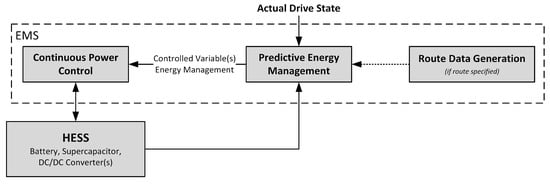
Figure 1.
Concept for the architecture of an energy management system for battery and supercapacitor HESS.
Route data generation determines all information relevant to the power demand and energy consumption for the route, such as the gradient of the route or the current traffic situation. This enables the energy management system to consider information about the route to be driven.
If the route and route data are known, these and the current state of the HESS are used by the predictive energy management system to determine an operating strategy for power control by calculating one or more suitable control variables for the further course of the route. This is achieved by taking a global view of the operation of the continuous power control and the resulting HESS utilisation based on a prediction of the electrical power demand profile from the generated route data. In addition, to enable robust operation of the energy management system against deviations due to unpredictable or unreliable predictable events, a correction of the controlled variable(s) is performed depending on the current driving and HESS state. If the route is not known and thus no global consideration of the operating strategy is possible, the necessary controlled variables for continuous power control can be formed based on the current driving and HESS state. This makes it possible to operate the energy management system even on routes that are not known in advance.
Based on the calculated operating strategy in the form of the control variables as well as the current HESS state, the continuous power control is intended to ensure the distribution of the electrical power consumption and output to the battery and supercapacitor in real time. The implementation required for this can be carried out using either a rule-based approach or a real-time capable optimisation approach. Depending on the chosen approach and its implementation, the variables of the HESS to be considered for the control of the power distribution result. Furthermore, this leads to the control variables that can be varied by the predictive energy management.
3.1. Objectives and Global Controlled Variables
The energy management system is to be used in such a way that a targeted increase in energy efficiency or battery life is pursued. Accordingly, an optimal distribution of the power to the battery and supercapacitor must minimise the influences opposing the objective.
For an increase in energy efficiency, it is necessary to minimise the energy consumption and energy losses of the entire HESS as best as possible. This means that the energy extraction from the battery as well as the losses at the battery, the DC/DC converter(s), and the supercapacitor should be kept to a minimum.
To increase the battery life, the battery should be used little and preferably in an ideal operating range. A reduction in battery use can be achieved by minimising both energy consumption and energy output. For operation in the optimal range, current peaks or rapid current changes at the battery should also be avoided. Furthermore, in order to increase battery life, power dissipation must be kept to a minimum by energy management due to the resulting thermal load.
Regardless of the specific objective pursued (increasing efficiency or lifetime), implicit contributions can be made to increasing battery lifetime and energy efficiency. In the case of minimising battery losses, there is even a joint measure. In addition, a reduction in battery use usually leads to less energy being drawn from the battery. Conversely, if the battery consumes less energy, it may be used less.
3.2. Continuous Power Control
The distribution of the power requirements from the vehicle’s electrical system to the battery and supercapacitor is intended to be carried out in real time by the continuous power control. For this, the respective operating limits of the energy storage devices, the specifications of the control variables by the predictive energy management and the current HESS state must be considered. The concept for continuous power control is shown in Figure 2.
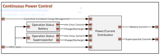
Figure 2.
Concept for continuous power control.
The operating status of the energy storage devices is determined based on the status of the HESS or the battery and the supercapacitor, which are determined from the respective supervision functions. Depending on the operating status, it is decided whether charging or discharging is currently possible and how much current can be drawn or delivered. Based on the status of the battery and supercapacitor, the given control variable(s) of the energy management and the HESS status, the power/current distribution can then take place.
The current distribution specifies how much current the supercapacitor and the battery are to be loaded with. This is implemented by at least one DC/DC converter on one of the energy storage units, which regulates the respective current value. If only one DC/DC converter is installed in the energy storage system, the other energy storage device is loaded with the difference to the load current. If both the battery and the supercapacitor are connected to the DC bus with a DC/DC converter, both specifications can be explicitly set. The implementation of the power/current distribution can be rule-based or through approaches for instantaneous optimisation. In addition, the implementation defines the possible control variables for predictive energy management.
3.3. Predictive Energy Management
Predictive energy management determines the operating strategy for continuous power control by calculating one or more suitable control variables. The concept, which is shown in Figure 3, provides a global optimisation of the operating strategy and a calculation of the control variables for the power control. If the route to be driven is known, a globally optimised strategy for the operation of the continuous power control is calculated. Based on this, the corresponding control variables for the power control are calculated, taking into account the HESS and driving status as well as the route data, if applicable. If the route is not known, the necessary control variables can be calculated independently on the basis of the HESS and driving status. Which control variables can be used to determine the operating strategy depends on the concrete design of the continuous power control. The calculation of the strategy as well as the calculation of the controlled variables are also not subject to real-time requirements. This makes it possible to use a computationally time-intensive global optimisation for energy management. This can be repeated regularly during the course of the journey so that the strategy can react to deviations from the previous calculated prediction and strategy.
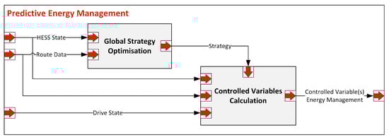
Figure 3.
Concept for predictive energy management.
A problem that must be solved by predictive energy management is that the supercapacitor can only store relatively little energy compared to the battery. If the supercapacitor is fully charged or discharged, no more power or current can be absorbed or delivered and the battery must fulfil the power or current requirements independently. Thus, the supercapacitor cannot always be used as required by the continuous power control. Accordingly, the predictive energy management must regulate the operation of the continuous power control by specifying corresponding control variables. In doing so, the global optimisation of the operation of the power control should take place in such a way that a targeted increase in battery life or energy efficiency can be achieved.
3.3.1. Global Optimisation of Operating Strategy
The global optimisation of the operating strategy uses the given route data for an energy and power prediction, which is required as the basis for the actual optimisation calculation. During optimisation, the control variables of the continuous power control are varied in order to influence the distribution of the load current to the battery and supercapacitor. In doing so, optimal values for the entire route or specifically for individual route sections can be achieved. Based on the resulting distribution of the current, the quality of the respective operating strategy is then assessed with a corresponding objective function. To carry out the optimisation, a modelling of the continuous power distribution and the HESS used is required, which calculates all the values necessary for the objective function on the basis of the given control variables.
The result is the global optimised operating strategy, which consists of at least one value for each controlled variable to be optimised. Not all possible controlled variables of the continuous power control must necessarily be determined by the global optimisation. Which controlled variables are to be calculated by the global optimisation depends on the concrete implementation of the power control. If the global optimisation provides for different results for different route sections, the strategy consists of several distance related values per controlled variable.
3.3.2. Calculation of Controlled Variables
The controlled variables for continuous power control are calculated on the basis of the current driving state, the HESS state and, if available, route data and the global strategy. In principle, the controlled variables can be calculated both as a function of the strategy and independently.
- If the route data and the associated global strategy are available, the controlled variables are read out accordingly. In addition, it is possible that corrections are made based on the current HESS and/or driving status.
- If no route data and accordingly no global strategy are available, the controlled variables must be calculated independently. This can be achieved based on the current HESS and/or driving status.
- Control variables that are not given by the global strategy can, on the one hand, be calculated predictive using given route data or based on the current HESS and/or driving state and, on the other hand be calculated instantaneous on the basis of the current HESS and/or driving state.
4. Global Optimisation of a Rule-Based Power Distribution
The implementation of the concept for an energy management system of an HESS is represented by a global optimisation of the operation of a rule-based power distribution over the route to be travelled by the vehicle.
4.1. Rule-Based Power Distribution
The rule-based power distribution is based on a distribution of the load current to the battery and the supercapacitor according to defined current and voltage ranges. The basic approach [28] for this is that the supercapacitor is to be used primarily for peaks and recuperation power. Based on this concept, the procedure for distributing the current is shown as pseudo-code Algorithm 1.
If load current () is requested from the vehicle electrical system, the battery control current () is used to check whether the battery can supply this without the aid of the supercapacitor. If this is not possible, the supercapacitor should provide the difference between the load and battery control current. If the supercapacitor cannot provide this current, only the maximum possible supercapacitor current () is applied and the battery is discharged with the difference to the load current. In the event that it is not possible to discharge the supercapacitor, the battery has to supply the total load current.
If the current demand is less than the battery control current, the battery can be used to charge the supercapacitor. Charging takes place with a defined charging current (), whereby the battery current should not exceed the battery control current. Accordingly, a maximum of the difference between the battery control current and the load current can be applied for charging the supercapacitor. If the supercapacitor cannot absorb the charging current or charging is not necessary, the battery is only used for the load current.
If the load current is negative and the supercapacitor cannot and should not be charged, the complete recuperation current is fed to the battery. If the supercapacitor is ready for a current draw, the recuperation current is distributed between the battery and the supercapacitor. In the process, the battery is charged with a predefined recuperation current () and the supercapacitor with the load current reduced by . However, it must be noted that the current consumption is limited by the minimum supercapacitor current (). If the supercapacitor cannot fully absorb the load current for this reason, the battery is charged with a correspondingly higher current.
In event of a supercapacitor fault, the corresponding supervision function would set maximum power () to zero or an adequate value and thus prevent or limit further current distribution to the supercapacitor. Anyway, due to its own monitoring function, the supercapacitor will only supply the power or current that is within the safe operating limits. A battery fault is handled similarly, so that the supervising battery management limits or prohibits usage. Since the battery is the main energy source of the vehicle, a fatal battery failure will inevitably lead to a vehicle break down.
| Algorithm 1: Rule-based distribution of the load current to the battery and supercapacitor. |
|
This concept makes it possible to influence the operation of the current distribution through several variables. In this way, it can be directly determined at which point the supercapacitor should emit current (battery control current ), how much current the battery should charge the supercapacitor with (charging current supercapacitor), and how much recuperation current the battery should draw (battery regeneration current). The distribution to the battery and supercapacitor is achieved by specifying current values that refer to the voltage level of the DC bus.
The integration of the rule-based current distribution into the continuous power control takes place according to the representation in Figure 4. In the process, the battery control current, the battery regeneration current, and the charging current for the supercapacitor are specified for the power distribution by the predictive energy management. In order to assess the operational readiness and possibilities of the supercapacitor, the HESS state is evaluated and a reference voltage for the supercapacitor determined by the predictive energy management is taken into account. The maximum permissible power of the supercapacitor, the permissible voltage range, and the current voltage are used to determine the maximum and minimum current that the supercapacitor can deliver or draw. The decision as to whether the supercapacitor may be charged in the case of recuperation or, if possible, should be charged by the battery is performed by a state machine. A change between the states “Charging Permitted/Necessary”and “Charging Forbidden/Not Required” occurs according to a comparison of the supercapacitor voltage with the maximum permissible voltage and the specified reference voltage. In order to avoid oscillation between the states Charge and Not Charge, a corresponding hysteresis is implemented via the state machine. The evaluation of whether current can be drawn from the supercapacitor is carried out by another state machine. This implements a hysteresis that ensures that the supercapacitor is only discharged again after complete discharge when sufficient energy is available, so that high-frequency oscillation between discharging and charging of the supercapacitor is prevented.
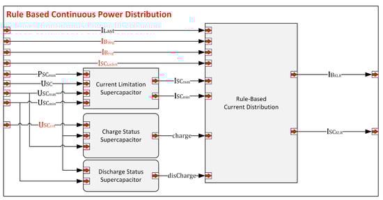
Figure 4.
Rule-based distribution of load current to battery and supercapacitor.
4.2. Predictive Energy Management
Predictive energy management specifies the battery control current, the battery regeneration current, the charging current, and the reference voltage for the supercapacitor. If route data are available, the battery control current and the battery regeneration current are determined by global optimisation. Depending on the selected optimisation approach, a route-related profile or a parameterisation is calculated for the entire route to be driven. On routes that are not known in advance, generally applicable default values are specified as part of the system design.
The value of the current with which the supercapacitor is charged from the battery when required can also be calculated as part of the global optimisation. However, the charging of the supercapacitor by the battery is limited upwards by the battery control current. Accordingly, the determination of this value can also be achieved by a coupling to the battery control current or the selection of a generally valid value.
For the reference voltage of the supercapacitor, it is not possible to determine a sensible value with validity for the entire distance, since this is used to decide situationally whether the supercapacitor should or may be charged. It must be possible to differentiate according to the actual driving condition and the position on the route so that, for example, no charging takes place by the battery before the start of a downhill drive, but rather this can be achieved by recuperation. Accordingly, a global optimisation would have to generate a profile related to the route. In addition, the reference voltage must have a dependency on the actual driving state. When the vehicle is at a standstill, sufficient energy should be available for the acceleration process and a reserve should be kept available for sudden braking while driving. Besides exclusive use for global optimisation, it is possible to evaluate route data in a rule-based manner and use it in the context of continuous control management.
The concrete realisation of predictive energy management takes place as shown in Figure 5. Here, the reference voltage for the supercapacitor is determined using selected route data and the current driving condition. The battery control current and the battery regeneration current are parameterised specifically for the route to be driven by global optimisation. The charging current for the supercapacitor is not changed and is provided by presetting a generally valid value of the power control.
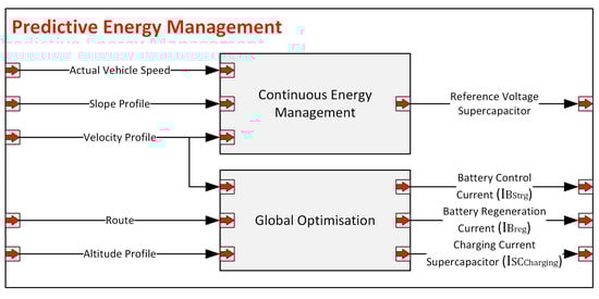
Figure 5.
Predictive energy management for route-specific parameter optimisation of rule-based power distribution.
4.2.1. Continuous Energy Management
The continuous energy management calculates the reference voltage for the supercapacitor, which the continuous power distribution uses to decide whether the supercapacitor may or must be charged. Figure 6 shows schematically how the reference voltage is calculated with existing route data. The calculations are always based on the charge level of the supercapacitor, which is then converted to the corresponding voltage value. The basic specification of the charge level is based on the average gradient that is to be expected on the following route section. If no route data are available, the default is a predefined generic value for the charge level. The actual speed of the vehicle is used to determine the corresponding kinetic energy and to derive how much reserve of the supercapacitor charge must be kept in reserve in order to be able to absorb it during braking and especially in case of sudden braking. The minimum charge of the supercapacitor is determined on the basis of the speed profile or the speed specification on the current section of the route. If the actual speed is less than the speed specification, the lower limit for the charge specification is calculated on the basis of the kinetic energy. If no route data and thus no speed profile are available, a speed target is estimated based on the current speed. This is to ensure that even without information on the route, sufficient energy is always held in reserve by the supercapacitor for any necessary acceleration processes.
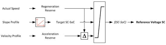
Figure 6.
Calculation of the reference voltage for the supercapacitor.
4.2.2. Global Optimisation
The global optimisation determines the optimal values for the battery control current and the battery regeneration current for the entire route to be driven or, in the case of multiple execution, for the route still to be driven. For this purpose, the power demand on the energy storage system is calculated by predicting the load profile on the given route. The route, the altitude profile, and the speeds to be driven on the route are taken into account. The power profile and a suitable HESS model are then used to simulate the journey with different values for battery control current and regeneration current. The continuous power control as well as the continuous energy management are already represented in the HESS model and thus taken into account for the optimisation. The quality of the parameter combinations can be evaluated specifically for increasing battery life or energy efficiency using corresponding objective functions. For an optimisation with the objective of increasing battery lifetime, the value of the objective function described in Equation (1) is minimised. It shows a minimisation of the battery use, the energy extraction from the battery, the battery losses, and the maximum battery current. In order to achieve a uniform reference and a unit-true value of the objective function, the described influences are all represented by current values at the level of the battery voltage. The battery utilisation is calculated using the average value of the battery current (). The energy extraction is described by the average of all discharge currents or positive battery currents (). The power loss of the battery is mapped to a current by means of the battery voltage () and the average value of this current is used for the objective function. The maximum value of the battery current () can be used in the objective function without conversions.
An increase in energy efficiency is achieved by evaluating the energy values of the battery and the HESS and is realised by minimising the objective function shown in Equation (2). Thus, both the energy consumption () for driving and the energy losses of the battery () are to be minimised. In addition, the losses at the DC/DC converter () and the supercapacitor () are taken into account by the objective function.
According to the optimisation objective, the value of the objective function is calculated for all variants of the battery control current and the battery regeneration current using the simulated results from the HESS model. Finally, the variant with the lowest value of the objective function is selected as the best possible parameterisation for driving the given route.
5. Simulation and Results
This chapter contains the validation of the developed and introduced energy management system to obtain a proof-of-concept. We simulate this using various real test routes , which represent different operating states of the vehicle. The validation was carried out using a HESS model in Simulink and consists of corresponding models of the components and the implementation of the energy management system presented in Section 4. The function of the HESS including the energy management system was simulated with a load profile for a journey on the given test route, which was calculated by the simulation tool CarMaker. CarMaker takes into account the respective route, the altitude profile, the speed limits, and traffic lights or the simulated load profile. As the validation is a proof-of-concept, no further simulations were performed to verify the real-time design criteria. Moreover, there is no actual hardware setup of the HESS system or even a selected control hardware that could be used in hardware simulation software.
5.1. Test and Simulation Setup
To achieve a proof-of-concept for the developed energy management system, an investigation was carried out on five test routes, each representing different scenarios. Table 1 provides an overview of the characteristics of the selected routes.

Table 1.
Characteristics of the selected test routes.
- Route-1: This test route represents a journey within a town predominantly with a speed limit of 30 km/h and is intended to test the principle behaviour of the energy management system on uphill journeys.
- Route-2: This route is to test the function of the energy management on longer journeys with motorway involvement and subsequent driving in an urban environment.
- Route-3: This route is designed to test the function of energy management on interurban journeys and accordingly represents a journey on state and federal roads, which may be interrupted in some cases by traffic lights.
- Route-4: This test route is intended to assess the behaviour of the energy management system for a journey on the main roads of a city and is characterised by a high number of traffic lights, which will lead to several starting and stopping procedures.
- Route-5: On this route, an uphill and downhill drive through two towns is presented. Accordingly, this test route is supposed to test how the energy management system handles combined uphill and downhill driving situations.
The modelling and parameterisation of the vehicle and energy storage system is based on [6]. A lithium–ion cell with a capacity of 60 Ah is modelled in MATLAB/Simulink and used as the main energy storage component. This cell type is used for the battery in the 2014 BMW i3 electric vehicle, which is utilised in this project. The parameters of the lithium–ion cells (Samsung SDI) used in the BMW i3 are shown in Table 2. The supercapacitor has to fulfil the role as an a high-power storage component in the energy storage system. Therefore, the modelling of the supercapacitor is based on a Maxwell BCAP3000 with a capacity of 3000 Farad at a voltage of 2.7 Volt, which fulfils the power requirement for this HESS [30]. The supercapacitor unit is made up of three parallel-connected strings, each consisting of 18 supercapacitors in series. Table 2 shows the detailed specifications of the HESS battery and supercapacitor unit. The corresponding component supervision functions for the battery and supercapacitor are not simulated in detail. Only the sub-functions that provide the EMS with information, i.e., about the status of the supercapacitor, are modelled.
Table 2.
Specifications of the HESS battery and supercapacitor unit.
The proof-of-concept of the energy management function is based on an evaluation of the simulation results with a focus on battery current, energy consumption, and energy losses. The average battery current can be used to illustrate the efficiency-increasing effect of the HESS and the energy management, while the average of the amount of battery current in direct comparison serves as an indication of the usage intensity of the battery. For a further analysis, the average of the battery discharge and charge currents are also calculated. In order to determine how effective the use of the supercapacitor is in preventing current peaks, the maximum and minimum battery currents are also analysed. Furthermore, the energy consumption from the battery generated during the journey is compared. It is assumed for the HESS application that the initial charge level of the supercapacitor of 90% SoC is applied by the battery before the start of the journey and is assigned to the energy consumption accordingly. In order to prevent self-discharge of the supercapacitor, it is discharged into the battery at the end of the journey. Furthermore, the energy losses at the battery and the entire HESS are evaluated.
As an initial scenario, the operation of the vehicle with only the battery as energy storage is simulated for each journey. The operation of the HESS controlled by the energy management system is carried out with a route-specific parameterisation for both of the given objectives, or target functions for increasing the battery life or energy efficiency.
For all variables, the relative deviation is presented when using the HESS with energy management compared to using only the battery. The relative deviation is calculated according to Equation (3). The respective result of the HESS simulation is used for and that of the referenced simulation of the battery for .
5.2. Increasing Energy Efficiency
The route-specific parameter optimisation to increase energy efficiency calculates the optimal values for the battery control current () and the battery recuperation current () for the test routes, which is, however, set to zero for four of the five routes. Only on the uphill/downhill circuit is a constant recuperation current drawn from the battery, while no current is to be delivered by a control current of zero as long as the supercapacitor is allowed to discharge. The effects on the relevant variables compared to battery use are shown in Table 3.
Table 3.
Relative deviations between simulation of the battery and the HESS with energy management with route specific parametrisation to increase efficiency.
Compared to battery-only operation, a reduction in the battery use and accordingly also of the average charging and discharging currents succeeds. However, there is no influence on the maximum current peaks, while the use of the supercapacitor can reduce the charging current peaks generated by recuperation on the inner-city route and the uphill/downhill journey.
In accordance with the objective, the battery energy consumption and the losses on the battery are significantly reduced. Only for route-2 is this somewhat lower, as the battery control current of 90 A is comparatively high and thus the battery is predominantly used for driving the motorway section, respectively, and has to be used anyway due to the low energy capacity of the supercapacitor.
By reducing battery losses and thus, for the most part, battery utilisation, parameter optimisation also contributes to an increase in efficiency and an extension of the service life. However, it is not possible to significantly reduce current peaks on any of the routes because, on the one hand, the reference through the objective function is missing and, on the other hand, situations always arise in which the supercapacitor cannot intervene due to given limitations.
As an example for increased energy efficiency, the current distribution, as well as the supercapacitors state of charge for a simulated drive of route-4, is shown in Figure 7. In this case, no recuperation current is distributed to the battery as long as the supercapacitor is able to be charged. Due to a low battery control current (10 A), the initial charge of the supercapacitor is quickly drained, which makes it always possible to distribute the recuperation current exclusively to the supercapacitor. In addition, through selected parameterisation, the charge resulting from braking is all the time directly used again for subsequent acceleration events. Thus, in case of route-4, it is possible to maximise the use of the supercapacitor, which leads to a significant reduction in energy consumption (−9.14 %).
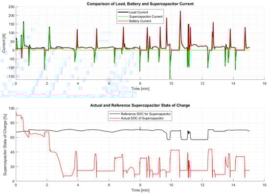
Figure 7.
Current distribution and supercapacitor state of charge (actual/reference value) for simulated journey on route-4.
5.3. Increasing Battery Lifetime
The route-specific optimisation of the parameters for distributing the load current with the aim of increasing battery life results in a battery regeneration current of zero amperes for all five test routes. For route-2 and route-3, each with motorway and interurban driving, thus constant driving at high speeds, the battery control current is also zero amperes, so that the supercapacitor is discharged whenever possible and necessary. On the other hand, higher battery control currents are selected for the uphill drive, the mountain course, and the drive in the city centre.
Compared to the exclusive use of the battery, this results in reduced battery usage in accordance with the objective, which is also reflected in lower average values for charging and discharging currents of the battery. The average battery current changes only slightly or even decreases. A reduction in energy consumption and battery losses is also achieved. The supercapacitor is used consistently on motorway and interurban journeys (route-2/-3), i.e., whenever this is possible and necessary. Accordingly, the parameterisation to increase battery life shows a consistent minimisation of battery charging current as shown in Table 4. Despite the fact that the maximum current value of a trip is minimised by the target function, a significant reduction in the maximum battery current is only achieved on the two routes with significant incline sections (route-1/-5), although in each case it is even possible to prevent all current peaks at the battery. In case of route-1, this is possible due to a high battery current of 50 A, which enables to supercapacitor to react exclusively to current peaks, as shown in Figure 8. For this, however, it is necessary that a parameter combination exists with which the supercapacitor can be used in the corresponding situation. Especially on longer journeys at high speeds, it is difficult to find such a combination for the entire route, as it is highly likely that the use of the supercapacitor will have to be limited due to situational circumstances.
Table 4.
Relative deviations between simulation of the battery and the HESS with energy management with route specific parametrisation to increase battery lifetime.
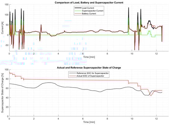
Figure 8.
Current distribution and supercapacitor state of charge (actual/reference value) for simulated journey on route-1.
5.4. Discussion
With the developed energy management, a general reduction in battery use, energy consumption, and energy losses of the battery can be achieved. Furthermore, with the route-specific optimisation of the parameters, the corresponding improvements can be achieved to reach the given objective. If energy consumption, battery losses, and losses of the entire HESS are reduced in order to increase energy efficiency, this also leads to a reduction in battery use, but not to a reduction or avoidance of power peaks. In addition to reducing battery use, increasing battery life also includes a reduction in energy consumption and battery losses, which explicitly contributes to increasing energy efficiency. It must also be noted that it is not always possible to use the supercapacitor according to the defined parameterisation. In applications on real routes, it is always possible that the supercapacitor can no longer be used for current output or consumption due to the route characteristics. This is especially the case when driving at constant speed and using the supercapacitor for energy supply, which, however, is already empty after a short time due to its limited energy capacity. However, this is independent of the EMS strategy and also unrelated to the speed driven in the process. Specifically after phases of constant speed, as well as in general, the supercapacitor is usually charged to the specified reference value when braking. In general, deviations can occur during the journey which cannot be predicted reliably or at all, but which require the supercapacitor to be used unscheduled and bring it to its limits. Accordingly, the supercapacitor can no longer be used as desired by the predictive energy management in subsequent driving situations. This is why situations such as sudden braking are handled by the continuous part of the energy management strategy calculation to prevent inappropriate utilisation of the supercapacitor.
6. Conclusions
Hybrid energy storage systems, which supplement a battery with a supercapacitor, in principle provide the potential to increase energy efficiency or battery life. An appropriate energy management system is intended to increase these effects. In theory, an optimised energy management system is designed to distribute the power in such a way that the requested power can be optimally divided both at the current instant and at all future instances. The developed concept for a route-based energy management system aims to achieve this by the functional separation between the continuous power regulation and the calculation of the underlying energy management strategy. The presented approach is using a predictive energy management for the calculation of the strategy for the operation of the power control. For this purpose, information about the route to be driven is used, and the generated route data are applied for a global consideration of the possible strategies for the energy management. This should lead to a global optimisation of the continuous power control operation based on predictions of the energy and dynamic behaviour of the vehicle on the planned route. By separating the continuous power regulation and the underlying strategy, the distribution of power to the battery and supercapacitor can take place in real time based on a given strategy, while more computational time can be dedicated to the calculation of the strategy and does not need to be performed in real-time. In addition, steps are added to make the strategy robust to deviations from the calculated prediction, events that are difficult to predict, or events that are not considered in the prediction. This concept thus shows that approaches for global optimisation become usable for a real-time application. A first realisation of the basic concept is a rule-based power distribution in combination with a predictive energy management. This includes both a rule-based power distribution based on data about the route to be driven and a global optimisation to adapt the strategy specifically to the route. Thereby, the operation of the power control can be controlled by parameters, which can be optimised for specific sections of the route or for the whole route. The approach presented in this work is implemented with a route-specific parameterisation, which determine the optimal parameters for driving on the given route according to the selected objective (increasing energy efficiency/battery lifetime) for the power management. The results show that even the use of a hybrid energy storage system consisting of a battery and supercapacitor with a default parameterisation can have a significant effect on increasing energy efficiency or battery lifetime compared to the use of batteries alone. By using the route-specific parameterisation, an even better effect can be achieved than the current effect with the standard parameterisation. Up to 9.14% of the average energy consumption of the battery can be reduced during an urban route. In terms of the battery lifetime, the average battery usage can be reduced up to 13.35% and the battery energy losses up to 62.72%. For further steps, the control of the power distribution, instead of the rule-based approach, an implementation of the continuous optimisation can take place, so that a redundancy of the reference to the objective can be achieved. For this, an efficient real-time optimisation must be developed in particular, as well as a design of the objective function that is coordinated with respect to the weightings. In addition, an energy management system coordinated with this power control must then be created, which regulates the use of the supercapacitor via the reference value for the required state of charge by a global optimisation and continuous regulation. In addition to the conceptual development, there is also the possibility of testing the system on a hardware setup, which has to be designed and built accordingly. This can help validate the operational capability of the proposed EMS and also provides an opportunity to verify the intended real-time capabilities, for example, through the use of hardware simulation software.
Author Contributions
Conceptualization, T.N., Y.R., R.K. and D.C.; methodology, T.N. and Y.R.; software, T.N. and Y.R.; validation, T.N. and Y.R.; investigation, T.N. and Y.R.; resources, R.K. and D.C.; data curation, T.N. and Y.R.; writing—original draft preparation, T.N. and Y.R.; writing—review and editing, T.N., Y.R., R.K. and D.C.; visualization, T.N. and Y.R.; supervision, R.K. and D.C.; project administration, T.N., Y.R., R.K., and D.C. All authors have read and agreed to the published version of the manuscript.
Funding
This work was carried out as part of VEHICLE project, sponsored by INTERREG V A Upper Rhine Programme—Der Oberrhein wächst zusammen: mit jedem Projekt, European Regional Development Fund (ERDF) and Franco-German regional funds (Baden-Württemberg, Rhineland-Palatinate and Grand Est). This work has been supported by the EIPHI Graduate School (contract ANR-17-EURE-0002) and the Region Bourgogne Franche-Comté.
Conflicts of Interest
The authors declare no conflict of interest.
Abbreviations
The following abbreviations are used in this manuscript:
| HESS | Hybrid energy storage systems |
| EMS | Energy storage system |
| MPC | Model predictive control |
| SOC | State of charge |
| DC | Direct current |
| Load Current | |
| Battery Control Current | |
| Supercapacitor Charging Current | |
| Battery Regeneration Current | |
| Supercapacitor Minimum Current | |
| Supercapacitor Maximum Current | |
| Battery Absolute Current | |
| Battery Discharging Current | |
| Battery Loss Current | |
| Battery Energy Consumption | |
| Battery Energy Loss | |
| DC/DC-converter Energy Loss | |
| Supercapacitor Energy Loss | |
| Weighting |
References
- Tschöke, H.; Gutzmer, P.; Pfund, T. (Eds.) Elektrifizierung des Antriebsstrangs: Grundlagen—Vom Mikro-Hybrid zum vollelektrischen Antrieb; ATZ/MTZ-Fachbuch; Springer: Berlin/Heidelberg, Germany, 2019. [Google Scholar]
- Kruppok, K. Analyse der Energieeinsparpotenziale zur bedarfsgerechten Reichweitenerhöhung von Elektrofahrzeugen, 1st ed.; Expert Verlag GmbH: Tübingen, Germany, 2020. [Google Scholar]
- Longo, M.; Zaninelli, D.; Viola, F.; Romano, P.; Miceli, R. How is the spread of the Electric Vehicles? In Proceedings of the 2015 IEEE 1st International Forum on Research and Technologies for Society and Industry Leveraging a Better Tomorrow (RTSI), Turin, Italy, 16–18 September 2015; pp. 439–445. [Google Scholar] [CrossRef]
- Allegre, A.L.; Trigui, R.; Bouscayrol, A. Different energy management strategies of Hybrid Energy Storage System (HESS) using batteries and supercapacitors for vehicular applications. In Proceedings of the 2010 IEEE Vehicle Power and Propulsion Conference, Lille, France, 1–3 September 2010; pp. 1–6. [Google Scholar] [CrossRef]
- Joud, L.; Da Silva, R.; Chrenko, D.; Kéromnès, A.; Le Moyne, L. Smart Energy Management for Series Hybrid Electric Vehicles Based on Driver Habits Recognition and Prediction. Energies 2020, 13, 2954. [Google Scholar] [CrossRef]
- Nguyen, T.; Kriesten, R.; Chrenko, D. Concept for Generating Energy Demand in Electric Vehicles with a Model Based Approach. Appl. Sci. 2022, 12, 3968. [Google Scholar] [CrossRef]
- Du Pasquier, A.; Plitz, I.; Menocal, S.; Amatucci, G. A comparative study of Li-ion battery, supercapacitor and nonaqueous asymmetric hybrid devices for automotive applications. J. Power Sources 2003, 115, 171–178. [Google Scholar] [CrossRef]
- Çağatay Bayindir, K.; Gözüküçük, M.A.; Teke, A. A comprehensive overview of hybrid electric vehicle: Powertrain configurations, powertrain control techniques and electronic control units. Energy Convers. Manag. 2011, 52, 1305–1313. [Google Scholar] [CrossRef]
- Tie, S.F.; Tan, C.W. A review of energy sources and energy management system in electric vehicles. Renew. Sustain. Energy Rev. 2013, 20, 82–102. [Google Scholar] [CrossRef]
- Zhang, C.; Vahidi, A.; Pisu, P.; Li, X.; Tennant, K. Role of Terrain Preview in Energy Management of Hybrid Electric Vehicles. IEEE Trans. Veh. Technol. 2010, 59, 1139–1147. [Google Scholar] [CrossRef]
- Camacho, E.F. Model Predictive Control, 2nd ed.; SpringerLink Bücher; Springer: London, UK, 2007. [Google Scholar] [CrossRef]
- Hredzak, B.; Agelidis, V.G.; Jang, M. A Model Predictive Control System for a Hybrid Battery-Ultracapacitor Power Source. IEEE Trans. Power Electron. 2014, 29, 1469–1479. [Google Scholar] [CrossRef]
- Santucci, A.; Sorniotti, A.; Lekakou, C. Model Predictive Control for the Power-Split between Supercapacitor and Battery for Automotive Applications. In Proceedings of the 2013 IEEE International Electric Vehicle Conference (IEVC), Santa Clara, CA, USA, 23–25 October 2013; pp. 1–7. [Google Scholar] [CrossRef]
- Choi, M.E.; Kim, S.W.; Seo, S.W. Energy Management Optimization in a Battery/Supercapacitor Hybrid Energy Storage System. IEEE Trans. Smart Grid 2012, 3, 463–472. [Google Scholar] [CrossRef]
- Borhan, H.A.; Vahidi, A. Model predictive control of a power-split Hybrid Electric Vehicle with combined battery and ultracapacitor energy storage. In Proceedings of the Proceedings of the 2010 American Control Conference, Baltimore, MD, USA, 30 June–2 July 2010; pp. 5031–5036. [Google Scholar] [CrossRef]
- Laldin, O.; Moshirvaziri, M.; Trescases, O. Predictive Algorithm for Optimizing Power Flow in Hybrid Ultracapacitor/Battery Storage Systems for Light Electric Vehicles. IEEE Trans. Power Electron. 2013, 28, 3882–3895. [Google Scholar] [CrossRef]
- Wang, L.; Collins, E.G.; Li, H. Optimal Design and Real-Time Control for Energy Management in Electric Vehicles. IEEE Trans. Veh. Technol. 2011, 60, 1419–1429. [Google Scholar] [CrossRef]
- Chen, H.; Xiong, R.; Lin, C.; Shen, W. Model predictive control based real-time energy management for a hybrid energy storage system. CSEE J. Power Energy Syst. 2020, 7, 862–874. [Google Scholar] [CrossRef]
- Choi, M.E.; Seo, S.W. Robust energy management of a battery/supercapacitor Hybrid Energy Storage System in an electric vehicle. In Proceedings of the 2012 IEEE International Electric Vehicle Conference, Greenville, SC, USA, 4–8 March 2012; pp. 1–5. [Google Scholar] [CrossRef]
- Shen, J.; Khaligh, A. A Supervisory Energy Management Control Strategy in a Battery/Ultracapacitor Hybrid Energy Storage System. IEEE Trans. Transp. Electrif. 2015, 1, 223–231. [Google Scholar] [CrossRef]
- Shen, J. Energy Management of a Battery-Ultracapacitor Hybrid Energy Storage System in Electric Vehicles; University of Maryland Libraries: College Park, MD, USA, 2016. [Google Scholar] [CrossRef]
- Moreno, J.; Ortuzar, M.E.; Dixon, J.W. Energy-management system for a hybrid electric vehicle, using ultracapacitors and neural networks. IEEE Trans. Ind. Electron. 2006, 53, 614–623. [Google Scholar] [CrossRef]
- Choi, M.E.; Lee, J.S.; Seo, S.W. Real-Time Optimization for Power Management Systems of a Battery/Supercapacitor Hybrid Energy Storage System in Electric Vehicles. IEEE Trans. Veh. Technol. 2014, 63, 3600–3611. [Google Scholar] [CrossRef]
- Gökce, K.; Ozdemir, A. An instantaneous optimization strategy based on efficiency maps for internal combustion engine/battery hybrid vehicles. Energy Convers. Manag. 2014, 81, 255–269. [Google Scholar] [CrossRef]
- Awerbuch, J.J.; Sullivan, C.R. Filter-based power splitting in ultracapacitor-battery hybrids for vehicular applications. In Proceedings of the 2010 IEEE 12th Workshop on Control and Modeling for Power Electronics (COMPEL), Boulder, CO, USA, 28–30 June 2010; pp. 1–8. [Google Scholar] [CrossRef]
- Dusmez, S.; Khaligh, A. A Supervisory Power-Splitting Approach for a New Ultracapacitor–Battery Vehicle Deploying Two Propulsion Machines. IEEE Trans. Ind. Inform. 2014, 10, 1960–1971. [Google Scholar] [CrossRef]
- Rosario, L.C.; Luk, P. Implementation of a modular power and energy management structure for battery-ultracapacitor powered electric vehicles. In Proceedings of the IET Hybrid Vehicle Conference 2006, Coventry, UK, 12–13 December 2006. [Google Scholar] [CrossRef]
- Carter, R.; Cruden, A.; Hall, P.J. Optimizing for Efficiency or Battery Life in a Battery/Supercapacitor Electric Vehicle. IEEE Trans. Veh. Technol. 2012, 61, 1526–1533. [Google Scholar] [CrossRef]
- Hu, T.; Li, Y.; Zhang, Z.; Zhao, Y.; Liu, D. Energy Management Strategy of Hybrid Energy Storage System Based on Road Slope Information. Energies 2021, 14, 2358. [Google Scholar] [CrossRef]
- Lahyani, A.; Venet, P.; Guermazi, A.; Troudi, A. Battery/Supercapacitors Combination in Uninterruptible Power Supply (UPS). IEEE Trans. Power Electron. 2013, 28, 1509–1522. [Google Scholar] [CrossRef]
Disclaimer/Publisher’s Note: The statements, opinions and data contained in all publications are solely those of the individual author(s) and contributor(s) and not of MDPI and/or the editor(s). MDPI and/or the editor(s) disclaim responsibility for any injury to people or property resulting from any ideas, methods, instructions or products referred to in the content. |
© 2023 by the authors. Licensee MDPI, Basel, Switzerland. This article is an open access article distributed under the terms and conditions of the Creative Commons Attribution (CC BY) license (https://creativecommons.org/licenses/by/4.0/).