


Derating of Squirrel-Cage Induction Motor Due to Rotating Harmonics in Power Voltage Supply


Abstract
:1. Introduction
2. Materials and Methods
3. Results
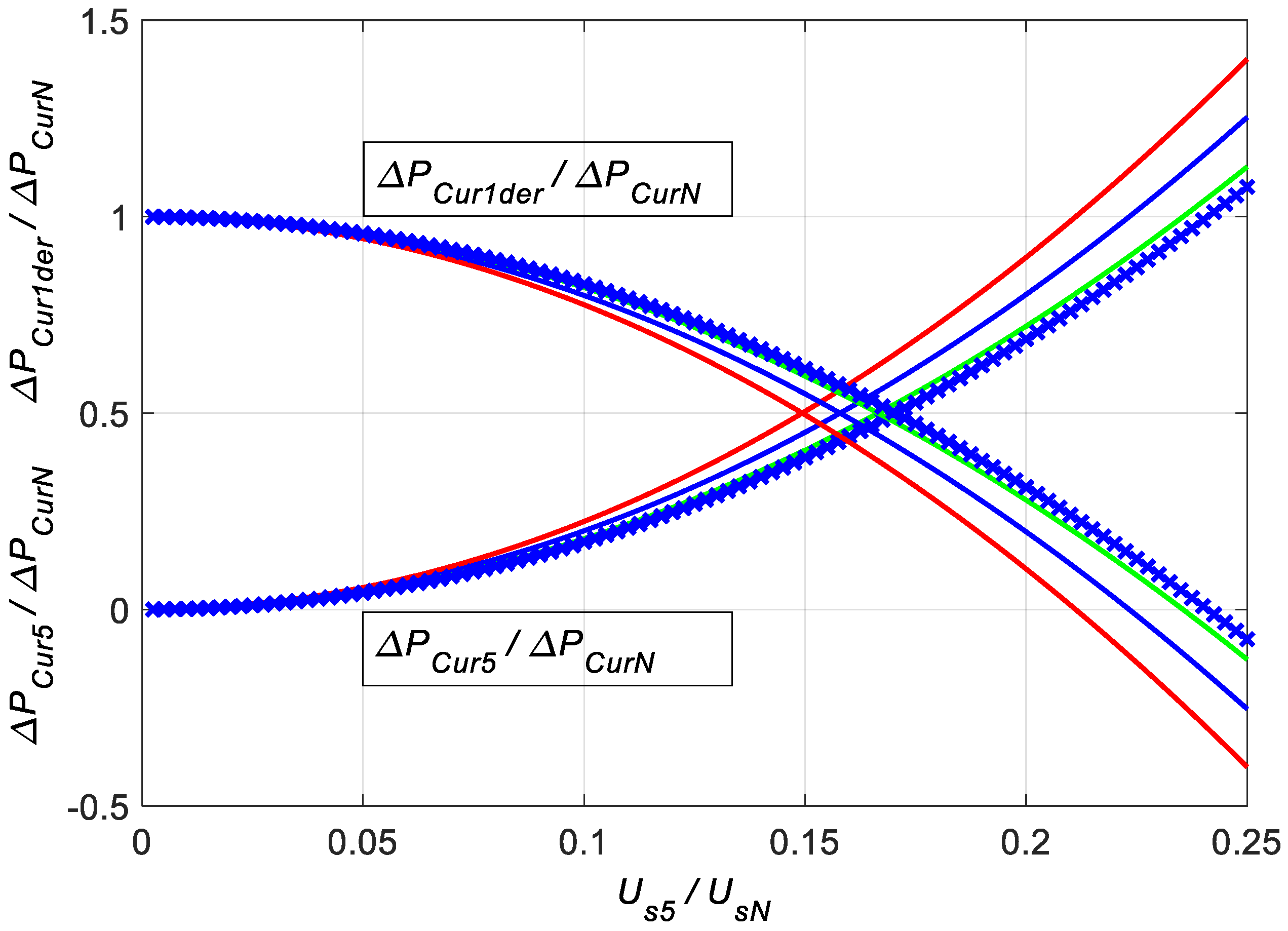
3.1. Derating Load Torque and Power
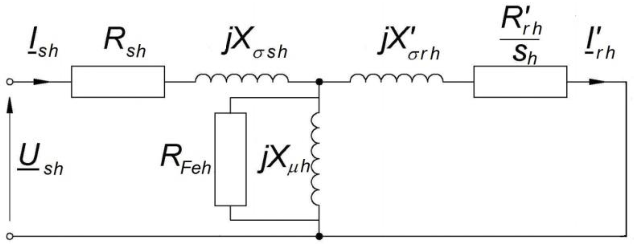
3.2. Identification of Motor Model Parameters
3.3. Models of Load Losses
- In model 1, it was assumed that the stator resistance and rotor resistance vary with the harmonic number according to the expression (21) and with the same power of x, but with different values of the coefficient a:Knowing the power of x from the approximation and the value of Rr1′ from (17) and the value of RrN’ from (18), as the value of Rrh’ for h = sN, allowed us to determine the values of coefficients ar (for rotor) and as (for stator):The values of both coefficients should be between 0 and 1. Values less than 0 would mean that the DC winding resistance is negative. Values greater than 1 would mean that the resistance value decreases with increasing frequency.
- In model 2, it was assumed that the stator resistance and rotor resistance vary with the harmonic number according to the expression (21) and with the same power of x and coefficient a:The value of the coefficient a should be in the range from 0 to 1, for the reasons given for model 1. Model 2 can be described as “optimistic” in relation to the value of load power losses in the rotor cage. These losses should be assessed as underestimated because it is practically impossible for the stator resistance to increase with frequency as fast as the rotor resistance, in which the skin effect in the cage bars occurs. The disadvantage of model 2 is the incorrect reproduction of the rotor resistance value in the rated state RrN’—for the tested machine it is overestimated.
- In model 3, it was assumed that the stator resistance is constant, and the rotor resistance, which varies with the harmonic number, is responsible for the entire increase in the short-circuit resistance of the machine with frequency:The variation of the rotor resistance with the harmonic number can be written by the equation:where: .The value of the coefficient a should be greater than the quotient Rs1/Rk1 so that the DC rotor resistance is greater than 0, and less than 1, so that the rotor resistance increases with frequency. For ar’, it means that it should be between 0 and 1. Model 3 can be described as “pessimistic” in relation to the value of load power losses in the rotor cage. These losses should be assessed as overestimated because it is practically impossible for the stator resistance not to increase with frequency. The disadvantage of model 3 is the incorrect reproduction of the rotor resistance value in the rated state RrN’—for the tested machine it is underestimated.
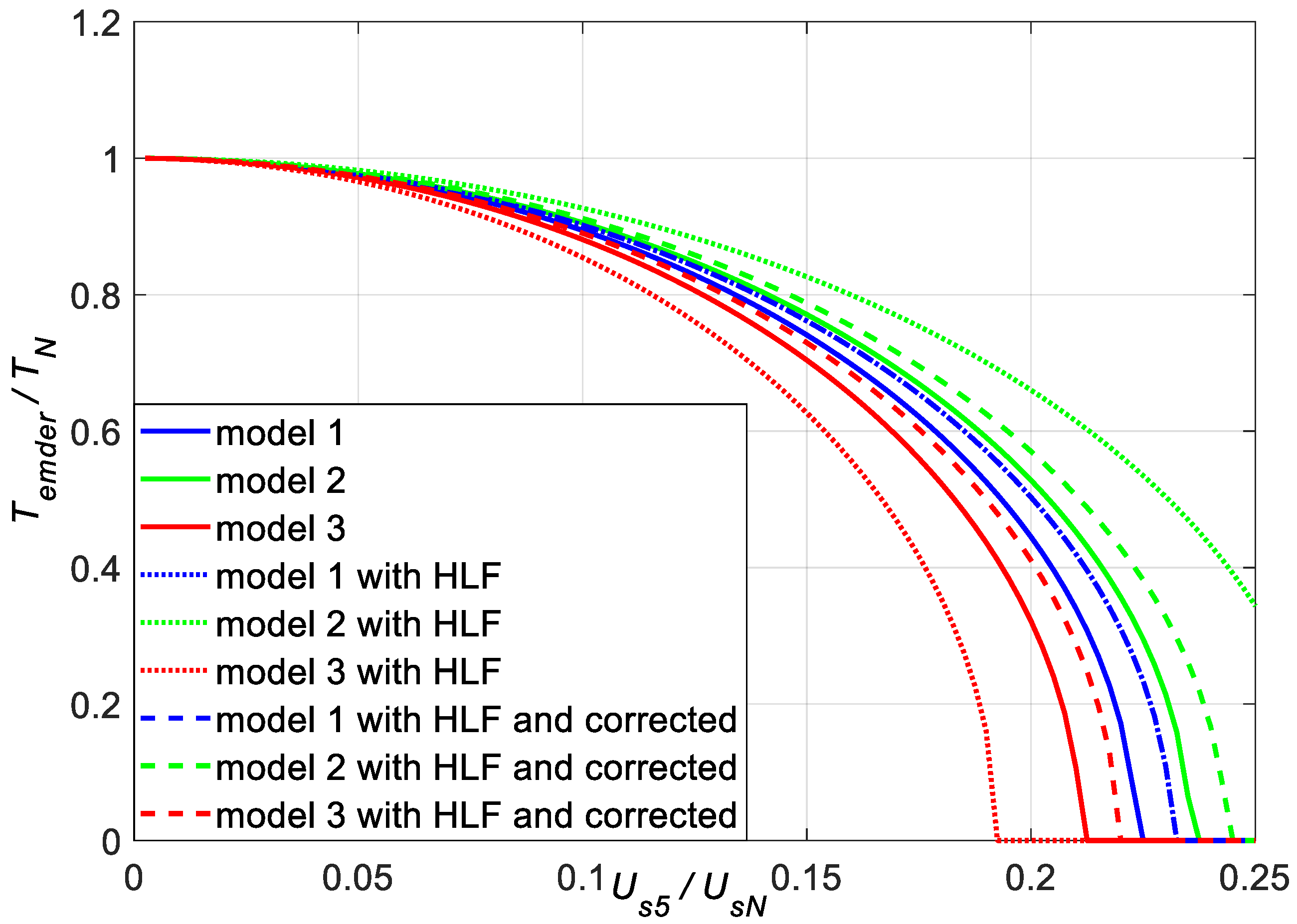
3.4. Derating Torque and Power
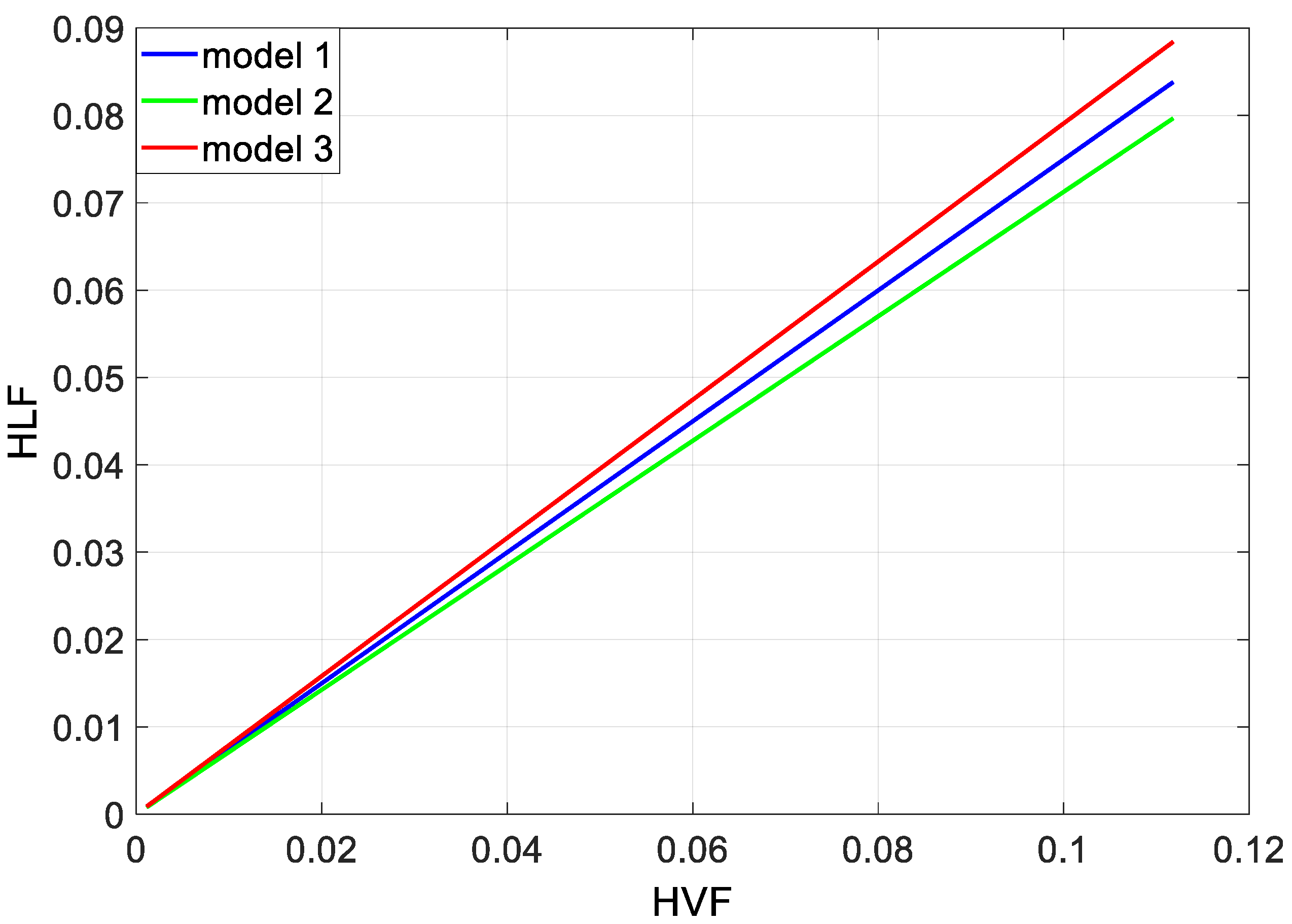
3.5. Harmonic Losses Factor
- For model 1:The product 3·Rr1′·IsN2 is the short-circuit power loss in the rotor when it is supplied with a definitional short-circuit voltage Uk1 (Ik1 = IsN) with rated frequency. The short-circuit cosφ of the motor is then cosφk1. Expression (42) can be written using the rated power losses in the rotor winding, which is more useful as a reference power than the product 3·Rr1′·IsN2, due to their presence in expressions (4)–(6):By defining the HLF as:we can write an expression for the rotor load losses due to higher harmonics:The HLF formula may be reduced to the HVF formula for the assumptions made in [3]. These are: (a) ar = 0 and a = 0 (then the variability of the resistances with the harmonic number is power function only), (b) cosφk1 = 0 (then the limitation of higher harmonic currents are the motor short-circuit reactances for these harmonics, without resistances), (c) x = 0.6, y = 0.8. In the expression for the total motor load losses from higher harmonics derived in [3], there is a numerical factor in front of the square of its value, which is 35 (42 in Formulas (31) and (A1) due to a different reference power—ΔPCuN). Its role in (45) is fulfilled by the following expression:For the tested motor C = 166.
- For model 2:In model 2, the following equality is fulfilled: ar = as = a, which simplifies expression (44) to the form:and expression (45) is fulfilled to the form:The disadvantage of model 2 is the incorrect reproduction of the resistance value RrN’. It has a negative impact on the accuracy of determining the coefficient C. For the tested machine C = 139, so the power losses in the rotor cage from higher harmonics are underestimated. This disadvantage can be corrected, inconsistently about model 2 by substituting in formula (48) instead of the expression ((1 − a)·sNx + a), the ratio of the resistance RrN’ (according to (18)) to the resistance Rr1′ (according to (17)).
- For model 3:In model 3, the coefficient ar in Formulas (44) and (45) was replaced by the coefficient ar’ as in Formula (28):The expression (45) takes the form:The disadvantage of model 3 is the incorrect reproduction of the resistance value RrN’. It has a negative impact on the accuracy of determining the coefficient C. For the tested machine C = 216, so the power losses in the rotor cage from higher harmonics are overestimated. This disadvantage can be corrected, inconsistently about model 3 by substituting in Formula (50) instead of the expression ((1 − ar’)·sNx + ar’), the ratio of the resistance RrN’ (according to (18)) to the resistance Rr1′ (according to (17)).
3.6. Determination of the DF Curves Based on the HLFs
4. Discussion
- The full range of possible rotor resistance changes with frequency was examined: from the variant where the full variability of the motor short-circuit resistance with frequency was assigned to the rotor resistance (model 3), through the variant where the variability of the rotor resistance was such that the rated value of this resistance was correctly reproduced (model 1), to the variant of identical variability of the stator and rotor resistance (model 2). Models 2 and 3 describe extreme variants because, in reality, it is not possible for the stator resistance to increase with frequency as quickly as the rotor resistance, and it is impossible for it to remain constant.
- In model 1, the determination of the coefficients as and ar was based on three resistance values: Rs1, Rr1′ = Rk1 − Rs1, RrN’. This guarantees the correct determination of the RrN’ resistance value from the approximation formula, and thus the correct determination of the rated power losses in the rotor. However, the variation of the rotor resistance with frequency was determined based on two values of this resistance, for the frequency fN (h = 1) and sN ∙ fN (h = sN), which are not far apart in the frequency domain. It reduces the reliability of determining the values of the coefficients as and ar in terms of the correct determination of the Rrh’ value for higher rotating harmonics.
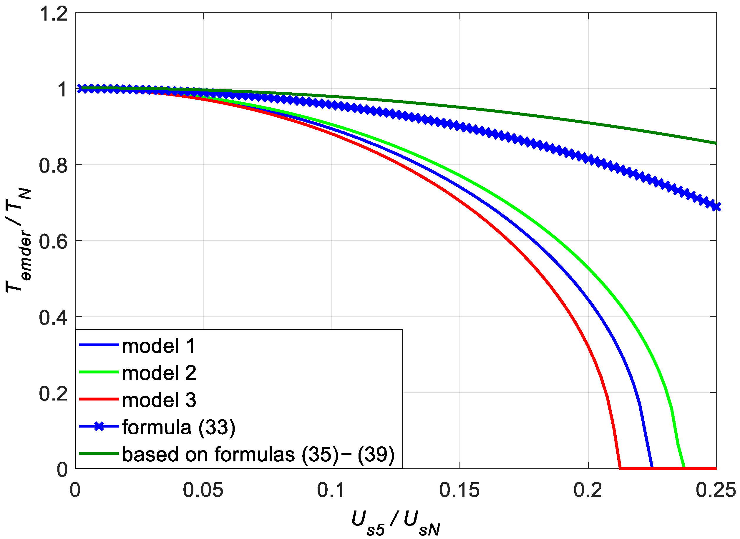
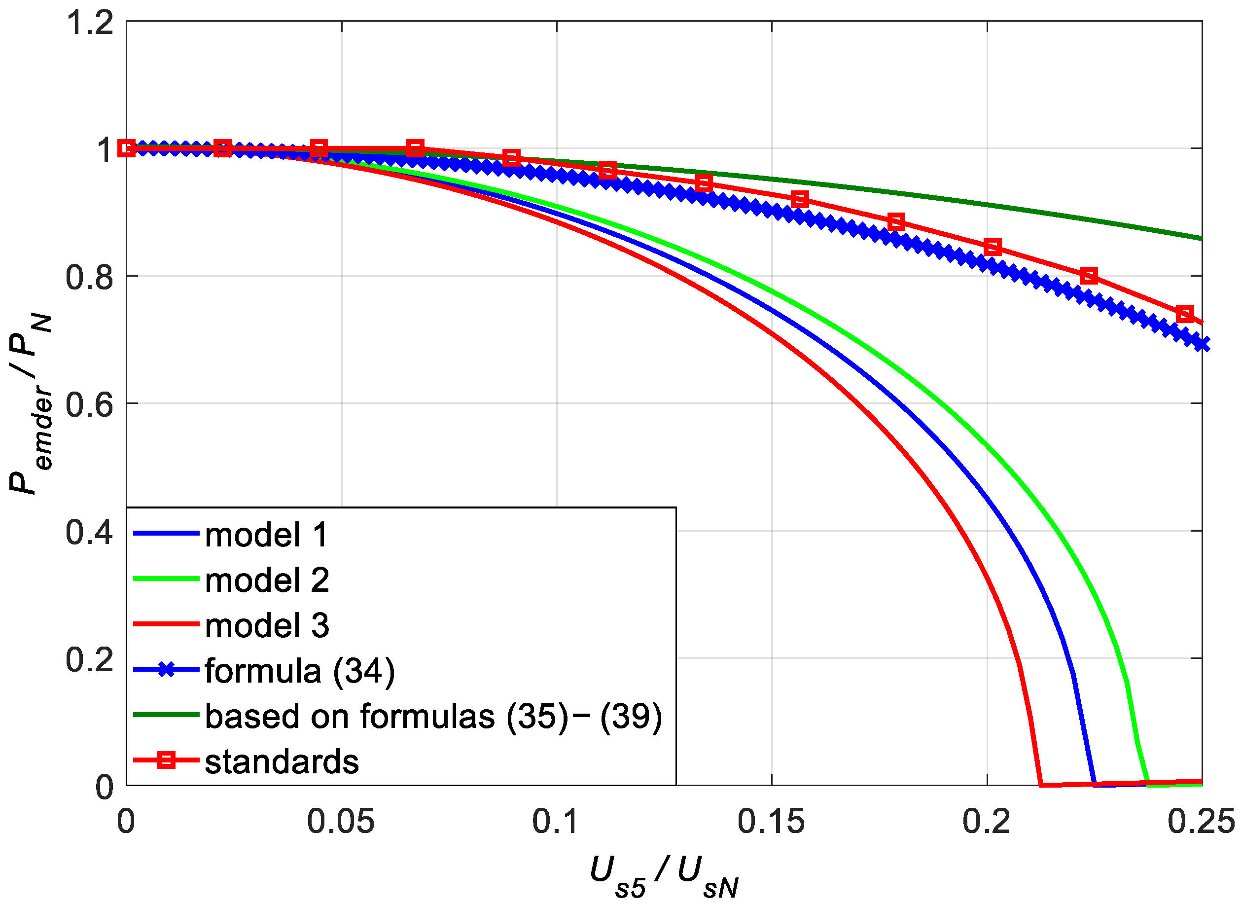
- For all three loss models, the curves of the admissible load torque and power according to (4) and (5) had a similar shape. However, from an operational point of view, the values of admissible torque and power were significantly different. For example, for us5 = 0.2, the differences between the values of the admissible load torque were +0.083TN and −0.123TN, relative to the curve of model 1. These differences decreased with the increase of the admissible torque—for us5 = 0.15, the corresponding differences were +0.03TN and −0.037TN. These were smaller differences than expected, but for operational reasons are too big to conclude that the choice of the load losses model is of no practical importance.
- The curves of the admissible motor torque and admissible power, described by Formulas (4) and (5), and models of load losses, differ significantly from the curves described by Formulas (33) and (34). The main reason for these differences is that the model of load losses presented in [3] applies to the total load losses in the motor. This model does not make it possible to separate rotor losses from the total load losses. It makes it impossible to link the admissible motor load torque with rotor losses. The derivation of the expression HVF and the expression for the total load losses of the motor supplied with a distorted voltage may be questionable. It is not understandable why the highly saturated value of the short-circuit reactance of the motor, measurement as the input reactance of the motor during its start-up, was used to determine the harmonic currents. The results of the calculations apply to the states of the motor with small currents not exceeding the rated current. During the start of the motor, the current is big—in [3] a phase current equal to 6.5IsN was assumed. Neglecting the short-circuit resistance in the expression for the harmonic current Ish seems to be an oversimplification and an unnecessary simplification. At such high frequencies as the frequencies of the rotor currents from higher rotating harmonics, the resistance of the cage bars can be very high, and consequently the value of the model parameter Rrh’ can be comparable to the value of the short-circuit reactance Xkh, and even more so with its saturated start-up value. In [3], the rated rotor resistance RrN’ and the short-circuit resistance of rotor Rr1′ were not differentiated. The model assumed powers of x = 0.6 and y = 0.8 for all squirrel-cage motors, which was not exact for the tested motor (Table 2). The consequence of all these assumptions and simplifications is that the admissible torque and power were much greater than those based on the losses models proposed in this paper. This is even though the curves of power losses in the rotor presented in Figure 3 and Figure 6 are not much different from the curves based on loss models described by Formulas (23), (26), and (28). This may raise doubts as to the correctness of the derivation of Formulas (33) and (34), but an indirect confirmation of their correctness is the compliance of the curve of the admissible motor load power according to (34) with the curve given in [4]—Figure 5. The admissible power, according to [4] is greater than according to expression (34) consistently by approximately 2.5% of the rated motor power for each magnitude of the voltage of the 5th harmonic us5 (at us1 = 1).
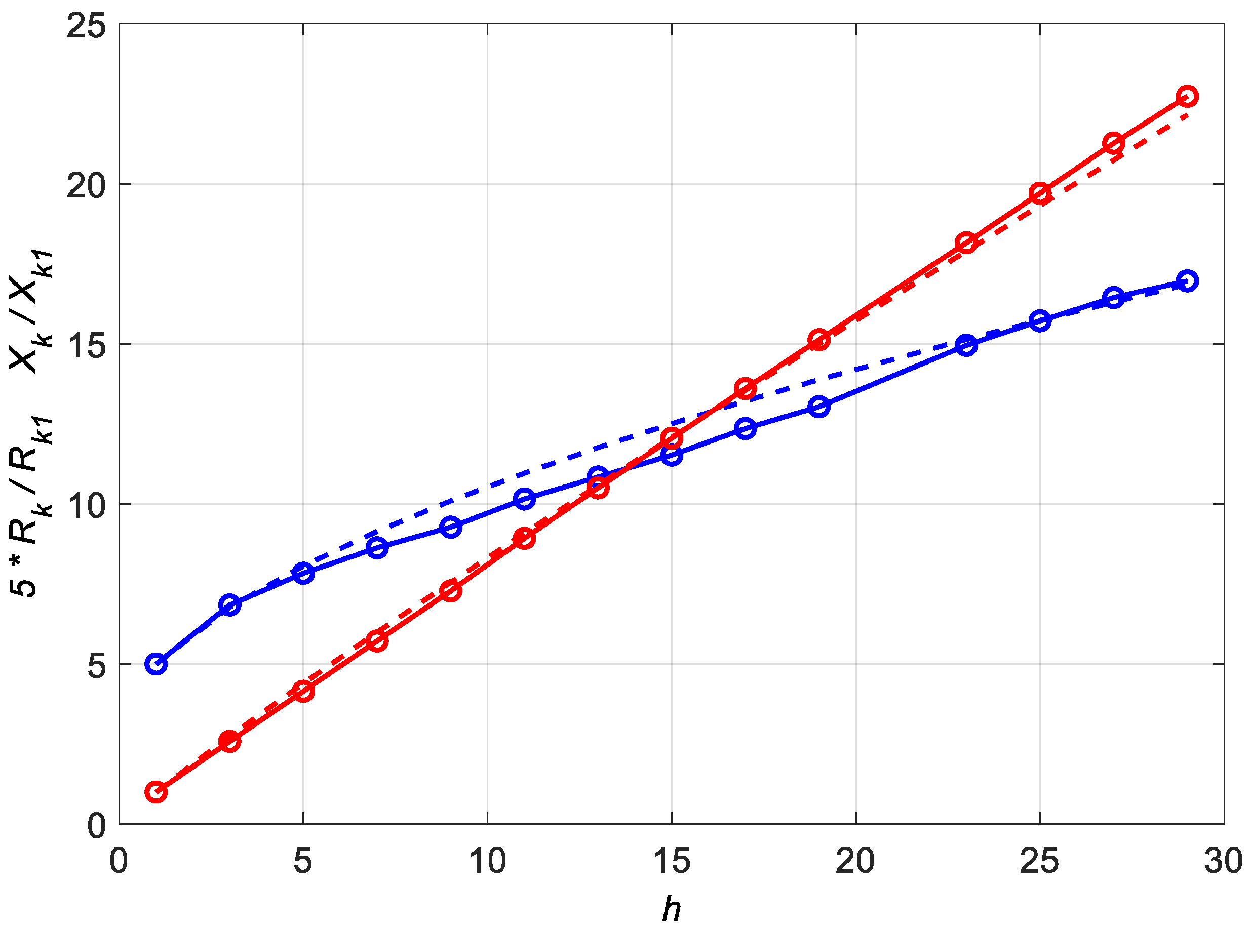
- The curves of the admissible torque and motor load power based on Formulas (4) and (5) and power loss models described by Formulas (23), (26), (28) also significantly differ from the curves based on Formulas (4) and (5) with stator current RMS value limit (35). This is because equation (35) does not account for the increase in the short-circuit resistance of the motor with the increase in the frequency of its current. The short-circuit resistance of the tested motor increases by 61% when the frequency increases from the rated (50 Hz) to five times the rated (250 Hz). Assuming that the increase in the rotor resistance with the frequency of its currents is the same as the stator resistance (ar = as = a, model 2), the rotor resistance for the 5th harmonic Rr5′ in relation to its rated value RrN’ increases by 205%. The increase in load power losses in the rotor associated with the increase in resistance is not included in the Formula (35). This explains the very overestimated values of the admissible torque and load power.
- The curves of the admissible torque and motor load power based on Formulas (52), (54), (56), and (58) theoretically should be identical to the curves according to (4) and (5), for the same models of losses. The differences result from the use of approximation formulas three or two times in Formulas (52), (54), and (56), which resulted in the summation of approximation errors. This problem does not occur when Formulas (4) and (5) are used directly; then, the approximation formula is used only once when determining the value of the expression (7).
- Assuming the identity RrN’ = Rr1′ and IrN’ = IsN (as in [3]) is a source of large errors in the value of the coefficient C present before the HLF square in Formula (45). After making these assumptions, the coefficient C reduces to 1/uk12, and its value for the tested machine is 60. The actual value is 166. It would be equal to 42, as in (33) and (34), if the short-circuit voltage of the tested machine was 15.5% instead of the real 13%. In the tested motor, Rr1′/RrN’ = 1.89, IsN/IrN’ = 1.21.
- The paper assumes that all additional load losses of the stator and rotor turn into heat in the windings of the machine, limiting the thermally admissible power losses for the fundamental harmonic of currents. This is a pessimistic assumption—some of these losses are outside the windings, not affecting the temperature of the windings or affecting it in part only. This problem requires further research. However, it was verified by calculations that for the tested motor, the rotor load losses from the 5th harmonic according to model 1 would have to be included in the calculations of the admissible torque and load power according to Formulas (4)–(7) only in 42%, so that these curves will be agreed with the according to Formulas (33) and (34) curves.
5. Conclusions
- The derating power curves given in [4,5] as a function of the HVF value for the tested motor are incorrect. For all three models of losses, the curves of the admissible motor power were definitely below the curves from [4,5]. Based on the derivation in Appendix A, it can be presumed that they are based on the considerations presented in [3]. The simplifications and inconsistencies result in a significant overestimation of the admissible torque and power.
- The accuracy of determining the variation of the rotor resistance Rrh’ with frequency has a key impact on the accuracy of determining the thermally admissible load torque of the induction motor. The key to determining DF is the knowledge of power losses from higher harmonics of the supply in the rotor, and not in the whole motor overall.
- The introduced HLF according to (44) differs from the well-known HVF by its generalization for real conditions when cosφk1 > 0, a > 0, ar > 0, x ≠ 0.6, and y ≠ 0.8. For cosφk1 = 0, a = 0, ar = 0, and for x = 0.6, y = 0.8, the HLF formula is reduced to the HVF formula.
- The formulation of the HLF expression carries with it the duplication of mathematical approximation errors, which generates errors in determining admissible torque and power. These values are more accurately determined based on Formulas (4)–(7) directly, preferably with an approximation of rotor resistance variability with frequency according to model 1. This leads to the conclusion that the curves of the admissible motor power should be determined not as a function of HLF or HVF, but as a function of the sum of the rotor winding power losses from higher harmonics, according to (7).
- The curves of the admissible torque and the admissible power are not different.
- There is no reason why the variation of rotor leakage reactance and resistance with frequency should be the same in different induction motors. This variability is determined by the skin effect in the bars of the rotor cage. Squirrel-cage motors have cage bars with cross-sections of different shapes. Therefore, the skin effect occurs in them with different intensities. This thesis is confirmed by the results of simulations in [12], where the curves DF(HVF) were significantly different for different motors. There it was found that curve DF(HVF) also depended on the number of pole pairs of the machine, its size and rated power, its design, and efficiency class.
Funding
Data Availability Statement
Conflicts of Interest
Appendix A
References
- Mboving, C.S.A.; Hanzelka, Z. Different approaches for designing the passive power filters. In Proceedings of theXII International School on Nonsinusoidal Currents and Compensation, Łagów, Poland, 15–18 June 2015. [Google Scholar]
- Drabek, T. Operation of an induction motor supplied by voltage containing subharmonics. Sci. Technol. Innov. 2017, 1, 27–34. [Google Scholar] [CrossRef]
- Cummings, P.G. Estimating the effect of system harmonics on losses and temperature rise of squirrel-cage motors. IEEE Trans. Ind. Appl. 1986, 6, 1121–1126. [Google Scholar] [CrossRef]
- IEC 60034-17; Rotating Electrical Machines—Part 17: Cage Induction Motors When Fed from Converters—Application Guide. International Electrotechnical Commission: Geneva, Switzerland, 2022.
- NEMA. MG1 Motors and Generators; National Electrical Manufacturers Association: Arlington, VA, USA, 2019. [Google Scholar]
- Fuchs, E.F.; Roesler, D.J.; Kovacs, K.P. Aging of Electrical Appliances due to Harmonics of the Power System’s Voltage. IEEE Trans. Power Deliv. 1986, 3, 301–307. [Google Scholar] [CrossRef]
- De Abreu, J.P.G.; Emanuel, A.E. Induction motors loss of life due to voltage imbalance and harmonics: A preliminary study. In Proceedings of the Ninth International Conference on Harmonics and Quality of Power, Orlando, FL, USA, 1–4 October 2000; pp. 75–80. [Google Scholar]
- Sen, P.K.; Landa, H.A. Derating of Induction Motors Due to Waveform Distortion. IEEE Trans. Ind. Appl. 1990, 26, 1102–1107. [Google Scholar] [CrossRef]
- Lee, C.-Y.; Lee, W.-J. Effects of Nonsinusoidal Voltage on theOperation Performance of a Three-phase Induction Motor. IEEE Trans. Energy Convers. 1999, 14, 193–201. [Google Scholar]
- Jalilian, A.; Gosbell, V.J.; Perera, B.S.P. Performance of a 7.5 kW induction motor under harmonically distorted supply condition. In Proceedings of the Canadian Conference on Electrical and Computer Engineering, Halifax, NS, Canada, 7–10 May 2000; pp. 355–359. [Google Scholar]
- Bradley, K.J.; Cao, W.; Arellano-Padilla, J. Evaluation of Stray Load Loss in Induction Motors with a Comparison of Input–Output and Calorimetric Methods. IEEE Trans. Energy Convers. 2006, 21, 682–689. [Google Scholar] [CrossRef]
- Ferreira, F.J.T.E.; De Almeida, A.T.; Deprez, W.; Belmans, R.; Baoming, G. Impact of Steady-State Voltage Supply Anomalies on Three-Phase Squirrel-Cage Induction Motors. In Proceedings of the International Aegean Conference on Electrical Machines and Power Electronics, Bodrum, Turkey, 10–12 September 2007; pp. 1–9. [Google Scholar]
- Ferreira, F.J.T.E.; De Almeida, A.T.; Baoming, G. Three-Phase Induction Motor Simulation Model Based on a Multifrequency Per Phase Equivalent Circuit Considering Stator Winding MMF Spatial Harmonics and Thermal Parameters. In Proceedings of the XVII International Conference on Electric Machines (ICEM), Chania (Crete Island), Greece, 2–5 September 2006. [Google Scholar]
- Debruyne, C.; Desmet, J.; Derammelaere, S.; Vandevelde, L. Derating Factors for Direct Online Induction Machines when supplied with voltage harmonics: A critical view. In Proceedings of the IEEE International Electric Machines & Drives Conference, Niagara Falls, ON, Canada, 15–18 May 2011; pp. 1048–1052. [Google Scholar]
- Quispe, E.; Gonzalez, G.; Aguado, J. Influence of Unbalanced and Waveform Voltage on the Performance Characteristics of Three-Phase Induction Motors. Renew. Energy Power Qual. J. 2004, 1, 279. [Google Scholar]
- Frank, S.; Lee, K.; Sen, P.K.; Polese, L.G.; Alahmad, M.; Waters, C. Reevaluation of Induction Motor Loss Models for Conventional and Harmonic Power Flow. In Proceedings of theNorth American Power Symposium, Champaign, IL, USA, 9–11 September 2012. [Google Scholar]
- De Buck, F.G.G.; Giustelinck, P.; De Backer, D. A simple but reliable loss model for inverter-supplied induction motors. IEEE Trans. Ind. Appl. 1984, IA-20, 190–202. [Google Scholar] [CrossRef]
- Debruyne, C.; Corne, B.; Sergeant, P.; Desmet, J.; Vandevelde, L. Evaluation of the Additional Loss due to Supply Voltage Distortion in relation to Induction Motor Efficiency Rating. In Proceedings of the IEEE International Electric Machines & Drives Conference, Coeur d’Alene, ID, USA, 10–13 May 2015; pp. 1881–1887. [Google Scholar]
- De Lima, E.C.; De Carvalho Filho, J.M.; Souza de Sá, J. Diagnosis of Induction Motors Operating Under Distorted and Unbalanced Voltages. In Proceedings of the 17th International Conference on Harmonics and Quality of Power, Belo Horizonte, Brazil, 16–19 October 2016; pp. 786–791. [Google Scholar]
- Donolo, P.D.; Pezzani, C.M.; Bossio, G.R.; De Angelo, C.H.; Donolo, M.A. Derating of Induction Motors Due to Power Quality Issues Considering the Motor Efficiency Class. IEEE Trans. Ind. Appl. 2020, 56, 961–968. [Google Scholar] [CrossRef]
- Lerch, T.; Rad, M. Influence of higher harmonics on losses in induction machines. Tech. Trans. Electr. Eng. 2016, 113, 13–24. [Google Scholar]
- Krzyściak, K. Determination of the Load Capacity of a Squirrel-Cage Induction Motor Supplied with Distorted Voltage. Master’s Thesis, AGH University of Science and Technology, Kraków, Polska, February 2022. [Google Scholar]
- Deraz, S.A.; Azazi, H.Z. Impact of Distorted Voltage on Three-Phase Induction Motor Performance. In Proceedings of the Nineteenth International Middle East Power Systems Conference (MEPCON), Cairo, Egypt, 19–21 December 2017; pp. 857–863. [Google Scholar]


| Data, Symbol, Unit | Value | Data, Symbol, Unit | Value |
|---|---|---|---|
| Operating duty | S1 | Efficiency at ¾ PN [%] | 92.8 |
| Power PN [kW] | 22 | Efficiency at ½ PN [%] | 91.4 |
| Torque TN [N∙m] | 142.4 | Efficiency class | IE3 |
| Frequency fN [Hz] | 50 | Insulation class | F |
| Speed nN [rpm] | 1475 | Weight (IMB3—feet) [kg] | 200 |
| Slip sN | 0.0167 | Rotor moment of inertia J [kg∙m2] | 0.185 |
| Number of pole pairs p | 2 | Degree of protection | IP55 |
| Voltage UN [V] | 690 Y/400 Δ | Climatic execution | N |
| Current IN [A] | 23.8 Y/41.1 Δ | Ambient temperature [°C] | up to +40 |
| Maximum torque [N∙m] | 3.4·TN | Altitude above sea level [m] | up to 1000 |
| Starting torque [N∙m] | 3.2·TN | Cooling method | IC411 |
| Starting current [N∙m] | 8.5·IN | No-load power P0 [W] | 931 |
| Power factor cosφN | 0.83 | No-load current I0/IN | 0.528 |
| Power factor at ¾ PN | 0.79 | Mechanical losses ΔPmech0 [W] | 86 |
| Power factor at ½ PN | 0.67 | Core losses ΔPFe0 [W] | 722 |
| Efficiency ηN [%] | 93.0 | Short-circuit voltage uk1 = Uk1/UN [%] | 13.0 |
| Coefficient | Value |
|---|---|
| a | 0.592 |
| x | 0.57 |
| y | 0.92 |
| as | 0.780 |
| ar | 0.477 |
| ar’ | 0.343 |
| HVF | HLF Model 1 | DF Model 1 | DF by [3] | DF by [4,5] | DF by [20] | DF by [12] | DF by [23] |
|---|---|---|---|---|---|---|---|
| 0.04 | 0.030 | 0.919 | 0.966 | 0.985 | 0.983 | 0.915–0.985 | 0.973 |
| 0.06 | 0.045 | 0.810 | 0.923 | 0.945 | 0.931 | 0.790–0.975 | 0.926 |
| 0.08 | 0.060 | 0.626 | 0.859 | 0.885 | 0.856 | 0.580–0.960 | 0.839 |
| 0.10 | 0.075 | 0.087 | 0.767 | 0.800 | 0.758 | 0.300–0.950 | 0.773 |
| 0.12 | 0.090 | 0 | 0.640 | 0.660 | 0.645 | 0.240–0.920 | 0.700 |
Disclaimer/Publisher’s Note: The statements, opinions and data contained in all publications are solely those of the individual author(s) and contributor(s) and not of MDPI and/or the editor(s). MDPI and/or the editor(s) disclaim responsibility for any injury to people or property resulting from any ideas, methods, instructions or products referred to in the content. |
© 2023 by the author. Licensee MDPI, Basel, Switzerland. This article is an open access article distributed under the terms and conditions of the Creative Commons Attribution (CC BY) license (https://creativecommons.org/licenses/by/4.0/).
Share and Cite
Drabek, T. Derating of Squirrel-Cage Induction Motor Due to Rotating Harmonics in Power Voltage Supply. Energies 2023, 16, 735. https://doi.org/10.3390/en16020735
Drabek T. Derating of Squirrel-Cage Induction Motor Due to Rotating Harmonics in Power Voltage Supply. Energies. 2023; 16(2):735. https://doi.org/10.3390/en16020735
Chicago/Turabian StyleDrabek, Tomasz. 2023. "Derating of Squirrel-Cage Induction Motor Due to Rotating Harmonics in Power Voltage Supply" Energies 16, no. 2: 735. https://doi.org/10.3390/en16020735
APA StyleDrabek, T. (2023). Derating of Squirrel-Cage Induction Motor Due to Rotating Harmonics in Power Voltage Supply. Energies, 16(2), 735. https://doi.org/10.3390/en16020735