Abstract
Support technology faces challenges in view of the large deformation of surrounding rock in three-soft coal roadways under high horizontal stress in Zijin Coal Mine, China. Geostress near the tested working face of the mine was measured and its distribution law was analyzed through theoretical analysis, numerical simulation analysis, and field measurement. The original supporting scheme of the three-soft coal roadway on the tested working face was analyzed to discover the deformation and failure mechanism of the surrounding rock of the original supporting roadway and the control measures. An optimized support scheme of H-G (hollow grouting) anchor cables, high strength bolts, W-shaped steel belts, metal meshes, and sprayed concretes was proposed for field applications. Based on the roadway in the tested 3201 working face at Zijin Coal Mine, the technical parameters for optimizing the combined support of the roadway were determined. The following results were be obtained through field measurement. The roadway was kept intact after excavation and the optimized support scheme was adopted in the three-soft coal roadway. No obvious deformation in appearance existed in the roof, floor, and roadway coal sides. Compared with the original support scheme, the stability of the roadways was improved visibly. The displacement of the roadway roof decreased from 100 to 30 mm, and that of the roadway coal walls decreased from more than 100 mm to less than 50 mm. This work verifies the effectiveness of a combined support scheme of H-G anchor cables, high strength bolts, W-shaped steel belts, metal meshes, and sprayed concretes to control deformations of surrounding rock in three-soft coal roadways. The new support scheme has good social and economic benefits and can be used as a reference for other roadway supports under similar conditions.
1. Introduction
Three-soft coal roadway refers to soft roof, soft floor, and soft coal quality. A three-soft coal roadway should meet the following requirements [1,2,3]: (1) according to Ref. [1], coal seams with sturdiness coefficient f < 1 are classified as weak coal seams (Platt’s coefficient f, also known as rock sturdiness coefficient and fastening coefficient, is 1/10 of the ultimate uniaxial compressive strength of rock and is dimensionless); (2) uniaxial compressive strength of direct roof rock of the coal roadway σ ≤ 25 Mpa or joint spacing d ≤ 60 cm; (3) uniaxial compressive strength of the coal roadway floor σ ≤ 25 Mpa. Coal is irreplaceable as a conventional energy source and the demand for it is increasing. Deep mining of coal resources has become an objective and inevitable trend, as well as a common problem faced by coal-producing countries [4,5,6]. The maximum principal stress on roadways is mostly horizontal stress with increased mining depth, with regional and directional characteristics [7,8]. Roadway support, therefore, becomes difficult under high horizontal stress.
Shallowly buried coal seams have few geological structures, simple composition of stress fields, low-stress concentration caused by excavation, and small deformation and failure range of the rock surrounding roadways. This can be controlled through conventional support [9,10,11,12,13,14]. Underground disasters such as deformation and failure of supporting carriers, bump, and strong floor-heave of surrounding rock of roadways are closely related to the magnitude and direction of tectonic stress with increased mining depth [15,16]. Many fault-fold structures exist in deep roadways, and tectonic stress is prominent and evolves into maximum principal stress [17,18]. Dynamic disasters such as nonlinear large deformation, strong rheology, and support failure occur frequently in surrounding rock. Some coalfields in China [19,20], such as Xinwen, Yanzhou, Huainan, and Shanxi, have difficulties in surrounding rock control caused by high horizontal tectonic stress.
He et al. [20] studied the response characteristics of roadway surrounding rock with high horizontal tectonic stress and proposed a comprehensive control scheme of long anchors with high strength and high preload, large-diameter and high-strength anchor cables, U-shaped steel retractable support, and backwall grouting. According to the research of Li et al., Kang et al. [21] established a geostress database of coal mines in China. Zhang et al. [22] studied the three-soft roadway with uniaxial compressive strength of less than 3 MPa in Yanlong mine. A support method combining the reinforced U-shaped steel bearing with pressure relief drilling was proposed [23]; transferring surrounding rock stress and reducing stress-transfer intensity can control the floor heave of a high-stress chamber. Li et al. [24] put forward the concept of deep stress adjustment, reinforcement, grouting, and secondary support of three soft roadways. According to the research of Zhang et al. [25], high stress is transmitted from the two sides to the floor of the roadway and the floor is fractured and uplifted under high stress. In view of the major technical difficulties in the deformation control of the surrounding rock of the deep three-soft roadway, Zhang et al. [26] analyzed the deformation characteristics of the surrounding rock of the asymmetric roadway according to the specific geological mining conditions of Liuquan Coal Mine, and proposed the SRDC principle of the deep asymmetric roadway. Shen et al. [27] proposed a novelty approach of gob-side entry retaining in a thick three-soft coal seam. The engineering scheme includes roadway expansion, large section roadway support, cutting the roof to relieve pressure, and road-inside backfill body construction. According to the characteristics of rock burst of high horizontal stress roadway floor, Guo et al. [28] studied the rock burst mechanism of roadway floors with the background of the south track roadway Xingan mine. Chen et al. [29] systematically studied the deformation and failure characteristics of deep roadways with high horizontal stress in the Wanbei mining area, and proposed the support technology of bolt-net reinforcement and grouting.
The above scholars studied the distribution law of high horizontal geostress in underground coal mines as well as the deformation mechanism of surrounding rock and difficulties in the control technology of the deep three-soft roadway under high horizontal geostress. Research on surrounding rock control technology of three-soft roadways under high horizontal stress mainly focus on high strength and high preload long bolt support, large diameter and high strength cable support, U-shaped steel expansion support, rear wall grouting reinforcement, roadway pressure relief and stress adjustment, asymmetric support, and secondary reinforcement support. Moreover, there are few studies on surrounding rock control technology for the three-soft coal roadway under high horizontal stress with H-G anchor cable support as the core. Therefore, it is of significance to study surrounding rock control technology of three-soft coal roadways with H-G anchor cable support as the core under high horizontal stress.
Underground stress increases with increased mining depth, and the physical and mechanical environment of the roadway fundamentally changes. Stress and displacement distribution, deformation, and failure characteristics of the surrounding rock of the roadway are significantly different between shallow and deep roadways in response to horizontal geostress. The maximum principal stress of the roadway for three-soft coal roadways with high horizontal stress in deep mining is mostly horizontal stress, which has obvious regional and directional characteristics. Supporting a three-soft coal roadway becomes very difficult under high horizontal stress, and the roof easily cracks. Furthermore, the floor can be greatly damaged and floor-heave easily occurs. The deformation of the surrounding rock of the roadway cannot be controlled by conventional support. Taking Zijin Coal Mine in Shanxi as an example, the work studied the distribution law of high horizontal geostress in the mine and proposes a new support technology with H-G anchor cable support as the core. This technology solves the production problems in the field and enriches the theory and technology of roadway support. Meanwhile, it provides a reference for other similar geological conditions of roadway support and has great significance for safety and efficient production in coal mines.
2. Engineering Background
2.1. General Situation of Mine
Zijin Coal Mine, located in Nanguan Town, Lingshi, Shanxi, China, is at the junction of Huozhou, Fenxi, Lingshi, and Qinyuan. The minefield is about 4 km long from north to south and 9 km wide from east to west. It covers an area of 29.3 km2 and has geological reserves of 77.7 million tons. The designed annual capacity is 900,000 tons. The main coal-bearing strata in this minefield are the Upper Carboniferous Taiyuan Formation and the Lower Permian Shanxi Formation.
Coal seams 2 and 11 in the minefield are commercial. Coal seam 2 is mostly commercially stable, while coal seam 11 is locally commercially unstable. Coal seams 6, 9, and 10 are unminable. Coal seam 2 is located in the middle of the Shanxi Formation, with thickness of 0.40–2.70 m and average thickness of 1.98 m. The thickness of coal seam 2 in the whole well field is stable with little change. Coal seam 2 has a simple structure; it generally does not contain a stone band or contains only one layer, which is located in the roof of the coal seam. The roof is mostly mudstone, arenaceous mudstone, siltstone, and fine-grained sandstone, while the floor is mostly mudstone, arenaceous mudstone, fine-grained sandstone, and siltstone, which are the mining conditions of the three-soft coal seam. Coal seam 2 is high in the northeast and low in the southwest, with a maximum ground elevation of 1000 m.
At present, the 3200 working face has been mined; the 3201 material roadway has been constructed; the 3201 return air roadway is under construction; the 3201 working face has not been mined yet. The 3201 working face adopts a longwall backward mining method, fully mechanized coal mining, full-seam mining, and all-caving roof management method. The strike length of the working face is about 1200 m, with a dip length of 162 m; the average dip angle of the coal seam of 15°. The 3201 material roadway of the 3201 working face of coal seam 2 is the tested three-soft coal roadway, and its buried depth is about 590 m. Figure 1 shows the location of Zijin Coal Mine, and Table 1 shows the mechanical parameters at the roof and the floor strata of the tested coal roadway.
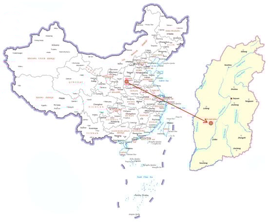
Figure 1.
Location of Zijin Coal Mine.

Table 1.
Mechanical parameters of the roof and floor strata of the tested coal roadway.
2.2. Measurement and Law Analysis of Geostress
Five measuring points were set for the geostress survey to analyze the directionality of the surrounding rock deformations of the roadway on the tested 3201 working face of the mine. Three measuring points were arranged in the 3201 working face (about 400 m away from the open-off cut of the 3201 working face) and two measuring points were arranged in the air-return main roadway (about 20 and 180 m away from the 3200 air-return roadway). The measuring points were arranged in the roof and floor strata of coal seam 2 (Figure 2).
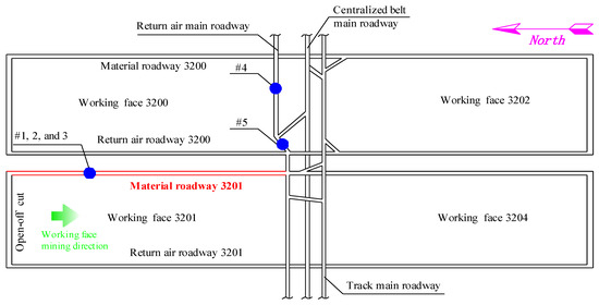
Figure 2.
Layout of geostress survey points.
A hollow-inclusion 3D stress measurement method was adopted for geostress survey, and the CSIRO HI-Cell type hollow-inclusion strain gauge developed by the ES&S Corporation in Australia was adopted (Figure 3). According to the drilling stress relief technique [30], a test block is isolated from the stress field imposed on it by the surrounding rock mass through core extraction (core-embedding technique). Figure 3 shows the principle of the stress relief process. Table 2 lists the measurement results of initial rock stress on the test working face.
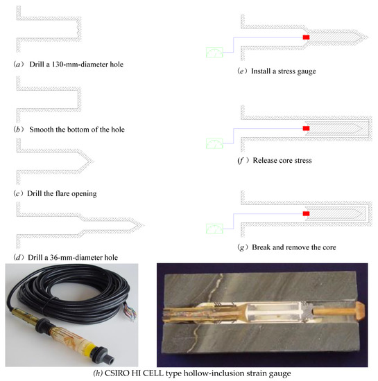
Figure 3.
Stress relief process of hollow-inclusion strain method.
Table 2.
Measurement results of initial rock stress on the tested working face.
According to the comprehensive analysis of the geostress survey results, the distribution characteristics of initial rock stress on the test working face are as follows:
- (1)
- The principal stress of the stress field is horizontal. The direction of horizontal stress in the 3201 working face is roughly east–west. The geostress survey results of the air-return main roadway in the west wing show that the geostress near the measuring point of the 3201 working face does not change, but still presents an east–west trend. The geostress direction away from the measuring point of the 3201 working face changes, and the direction of the geostress shifts to the south by about 20°;
- (2)
- Horizontal stress is generally greater than vertical stress; the maximum horizontal principal stress is about 18 MPa, which is 1.13–2.20 times more than vertical stress. It significantly affects the deformations and failure mode of the underground roadway and the mine-pressure behavior;
- (3)
- The direction of the maximum horizontal principal stress measured at the five measuring points is generally consistent, and the influence of horizontal stress on the stability of the roadway has directionality. Table 2 shows that the maximum horizontal principal stress component (σH) and the minimum horizontal principal stress component (σh) are positively correlated in the direction, yet their values are usually quite different. When the roadway axial direction is parallel to maximum horizontal principal stress, the influence of horizontal stress is the least, which is most favorable to roadway stability. When the axial direction of the roadway is perpendicular to maximum horizontal principal stress, horizontal stress has the greatest influence on roadway stability.
In summary, the geostress survey results of the 3201 working face of Zijin Coal Mine show that the maximum principal stress is horizontal stress, and the direction of horizontal stress is 56–95°. Geostress is mainly horizontal stress rather than vertical stress, indicating that horizontal stress significantly affects the stability of the surrounding rock of the underground roadway.
Most of the roof of the tested 3201 material roadway of the 3201 working face is cracked and broken, and the floor is significantly damaged with serious floor heave. The angle between the roadway and horizontal stress is approximately 90°, which hinders roadway support. The air-return main roadway in the west wing, the centralized belt main roadway in the west wing, and the track main roadway in the west wing are perpendicular to the direction of the tested roadway, and the states of these roadways are much better. The influence of horizontal stress on roadway stability has obvious directivity.
3. Original Support Scheme and Effect Evaluation of the Tested Roadway
3.1. Original Support Scheme of the Tested Roadway
The original support scheme of the tested 3201 material roadway of the 3201 working face adopted combined support of bolts and cables. The tested roadway roof bolt was steel-rebar of Φ 20 × 2400 mm, and the inter-row spacing was 750 × 700 mm. The roof was supported by six bolts per row; each bolt was anchored with 1 CK2355 and 1 ZK2355 anchoring agent and the M4 steel belt. Round steel bolts with a model size of 16 × 2000 mm were selected for the two sides of the roadway and the inter-row spacing was 900 × 700 mm. Three bolts were arranged on the left side of the roadway and four bolts were arranged on the right side. The anchor cable was made of 15.24 × 7000 mm steel hinged wire and each anchor cable was anchored with one CK2355 and two ZK2355 resin cartridges. The anchor cable was made of Φ12 mm iron plate as a reinforcement support and the inter-row spacing was 2250 × 1400 mm. The whole section of the roadway used a flexible concrete spray layer with a thickness of 100 mm and the reverse arch of the roadway floor. The shotcrete materials are general silicon no. 425, medium-coarse sand, and 2–4-mm stone. Figure 4 shows the cross-section of the tested roadway of the original support scheme.
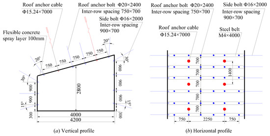
Figure 4.
Cross section of the tested roadway of the original support scheme (unit: mm).
3.2. Effect Evaluation of the Original Support Scheme of the Tested Roadway
The surrounding rock deformations of the roadway are large after adopting the combined bolt–cable support method in the 3201 working face of Zijin Coal Mine. The roof is broken and the concrete spraying layer falls off. The two sides of the surrounding rock of the roadway flake off seriously, and the bolt is exposed. The floor deformation and damage are also large, and the floor heave is serious. Figure 5 shows the tested roadway with the original support scheme.
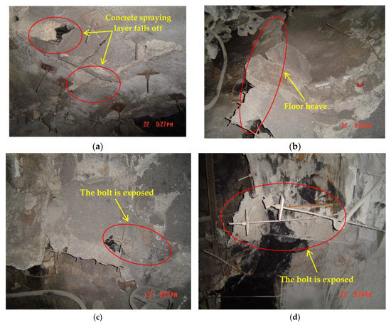
Figure 5.
Original support section of the tested roadway. (a) Roadway roof. (b) Roadway floor. (c) Left side of the roadway. (d) Right side of the roadway.
Combined with the geostress survey results and the field observation of the examined roadway, the comprehensive evaluation of the tested roadway shows that the serious deformations of the surrounding rock of the tested roadway are mainly as follows:
- (1)
- High geotectonic stress. According to the geostress survey results, the horizontal geotectonic stress of the tested roadway is about 18 MPa, which is 1.13~2.20 times the gravitational stress. The direction of maximum horizontal geotectonic stress is along the coal seam. Since the direction of the roadway is roughly perpendicular to the maximum horizontal stress, it is directly subjected to high stress and forms high-stress concentrations in the roof and floor, which are therefore easily damaged;
- (2)
- Three-soft coal roadway conditions. The tested roadway is located in coal seam 2, and the uniaxial compressive strength of the coal seam, immediate-roof arenaceous mudstone, and immediate-floor arenaceous mudstone is 10, 9, and 7.37 Mpa, respectively. The roadway is a three-soft coal roadway. The soft coal wall of a three-soft coal roadway is easily destroyed under high horizontal stress;
- (3)
- Failure of coal sides leads to the roof instability. The stability of the roadway roof is inversely proportional to the cube of the roadway span. When the actual roadway increases by 30%, roof displacement increases by 120%. When the failure of the coal side continues to extend to the interior, the actual roadway span increases, which greatly reduces roof stability. As a result, roof damage is serious in areas where the coal sides are damaged;
- (4)
- The surrounding rock (coal) of the roadway are weathered. The roadway roof and floor and coal walls have strong weathering properties, disintegrating and losing strength quickly when exposed to water and wind after excavation. The weathering of coal walls is prevented by thin shotcrete in the process of the roadway excavation, but the effect is limited;
- (5)
- Insufficient coal wall support. The two sides of the underground roadway of the coal mine are mainly supported by 2-m-long bolts with partial anchorage. Once the coal at the exposed end of the bolt is destroyed, the bolts will lose their supporting bearing function due to the failure of coal sides. What is more, when the yield range of the coal sides exceeds 2 m, whole bolts will be in the yield/broken zone because the bolt length is only 2 m. This greatly reduces the bolts’ supporting effect, even eliminating their supporting ability;
- (6)
- Insufficient roof support. The roof of the underground roadway in the coal mine is supported by bolts and cables. Anchor bolts and cables end in the soft mudstone or thin coal seam of the roof due to the limited length, and the ends do not reach the hard sandstone of the roof. When the soft rock of the roadway roof is damaged, the effects of anchor bolts and cables are limited. Furthermore, the bolts and cables of the original support scheme do not have enough preload. The roof deformation is small and the internal stress of bolts and cables is small at the early stage of roadway excavation, meaning that they cannot support the roof and causing stratification and destruction of the roof at an early stage;
- (7)
- Floor heave is caused by high horizontal stress. The immediate floor of the tested roadway in the coal mine is soft arenaceous mudstone. The arenaceous mudstone of the floor is prone to stratification under high horizontal stress. A single laminate without support breaks in the middle under axial pressure, which forms floor heave;
- (8)
- Changes in geological conditions cause local rock fragmentation, immediate-roof thinning, and roof fall. The spacing between the roofs in coal seams 1 and 2 decreases dramatically. When it becomes as thin as 1–2 m, rock integrity decreases due to the influence of the geological structure, which hinders roof support. The zone is accompanied by coal-side failure and floor heave.
To sum up, the deformation of two coal sides must be controlled to prevent the failure of the rock surrounding the tested roadway. The failure of coal sides can be controlled to gradually extend deeper through effective support. Then, the deformation of two sides of the roadway is reduced to increase the self-supporting ability of roof. Therefore, the roof of the roadway is designed as a semicircular arch and is supported by the high preload bolts and cables. The surrounding rock of the two sides and roof is reinforced by H-G cables. The floor is designed as a reverse arch and filled with concrete mixture material to improve floor strength and reduce heave deformation.
4. Analysis of the Deformation Mechanism of the Surrounding Rock in the Three-Soft Coal Roadway with High Horizontal Stress
4.1. Analysis of the Influence of High Horizontal Stress on the Stability of the Surrounding Rock of the Three-Soft Coal Roadway
According to the theory of maximum shear stress in rock mechanics [31,32,33,34,35], maximum horizontal stress is perpendicular to the two sides of the roadway when the roadway is parallel to the minimum horizontal principal stress. The high-stress difference between mainly affects the instability of surrounding rock when maximum horizontal stress is different from vertical stress. The horizontal stress is higher than vertical stress during the period after the excavation of the three-soft coal roadway. Therefore, the roadway is arranged at a certain angle to the direction of maximum principal stress for the stability control of the surrounding rock. This reduces the differences between the vertical stress and horizontal stress of the roadway, which is more conducive to the long-term stability of the rock surrounding the roadway. Figure 6a,b show the comparison between the surrounding rock stress state under the theory of maximum horizontal stress and the actual surrounding rock stress state during roadway excavation.
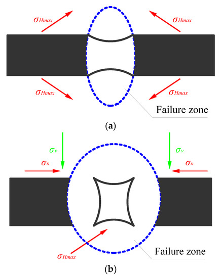
Figure 6.
Comparison of surrounding rock states under different stress conditions. (a) Roadway surrounding rock state considering only horizontal stress. (b) Surrounding rock state of the roadway with the actual stress state.
Most of the underground roadways in the Zijin Coal Mine have a 90° angle to horizontal stress. The roadway roofs are cracked and broken, with damaged floor, serious floor heave, and difficulties for roadway support. However, the conditions of other underground roadways perpendicular to the tested roadways are better, indicating that the influence of horizontal stress on roadways stability has obvious directivity.
4.2. Analysis of Reasonable Layout Direction for the Three-Soft Coal Roadway
Researchers have studied the influence of high horizontal stress on roadway layout [31,32,33,34,35], and the influence of high horizontal stress on roadways has also attracted attention. Figure 7 shows that the roadway axis is arranged along the z-axis; σn is stress perpendicular to the two sides of the roadway; σz is stress parallel to the axial direction of the roadway; σv is the vertical stress of the roadway roof. α is the angle between σz and minimum horizontal principal stress σh, and β is the angle between σz and maximum horizontal stress σH.
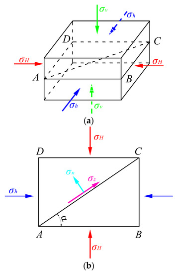
Figure 7.
Stress distribution in surrounding rock after roadway excavation. (a) Underground main stress field. (b) Main stress field of ABCD profile.
According to the horizontal stress measurement results, the horizontal stress of the Zijin Mining Area is σH > σv > σh, which is a σHv-type geostress field. The roadway layout direction should make the vertical side stress of the roadway equal to the roof stress in the σHv geostress field to achieve the most stable state in the surrounding rock of the roadway. The following equation should be applied [31,32,33,34,35]:
The optimal angle between the minimum principal stress and the axial direction of the roadway can be obtained by Equations (1) and (2) [31,32,33,34,35]:
The optimal angle of the roadway arrangement varies with principal stress (Table 3) [31,32,33,34,35]. When maximum horizontal principal stress σH = 1.25 γH and minimum horizontal principal stress σh = 0.75 γH, β = π/2 − α = π/2 − arccos (0)/2 = 45°. The angle is the optimal angle β between the roadway layout and the direction of maximum horizontal principal stress.
Table 3.
Relationship between optimal angle β of the roadway layout and the change of principal stress.
According to the maximum shear-stress failure criterion (Equation (4)) [31,32,33,34,35], the greater the stress difference between the two sides of the roadway and the roof, the worse surrounding rock stability.
When the angle between minimum principal stress and the axial direction of the roadway is 90° (β = 0°), the maximum stress difference is 0.25 γH. The stress difference and its ratio to other different angles are calculated and converted into percentages when used as the denominator to analyze the influence degree of roadway layout angles on surrounding rock deformations [31,32,33,34,35].
The surrounding rock deformation, repair, and reinforcement of the tested roadway of Zijin Coal Mine is a significant undertaking. Figure 8 shows the variation curve of stress ratios between the side of the mining roadway and roof along with the included angle β. The side stress of the roadway gradually approaches the roof stress with the increased included angle, and the stress difference decreases. When the angle between the roadway and maximum horizontal stress is 45°, the stress difference is the smallest, and the surrounding rock is the most stable, theoretically.
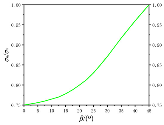
Figure 8.
Curves of stress ratios between two sides of the roadway and roof varying with β.
5. Optimization of the Roadway Support Scheme
5.1. Numerical Simulation Analysis
- (1)
- Construct a numerical simulation
According to the geological conditions of the 3201 working face in Zijin Coal Mine, theoretical analysis, and geostress survey data, a numerical calculation model of the three-soft coal roadway was constructed using FLAC3D6.0 software [36,37,38] (see Figure 9). The length and height of the design model were 50 × 40 m2. This simulation mainly analyzes the deformation of surrounding rock after adopting the optimization support scheme and the optimized support scheme of the tested roadway to determine the optimal support scheme of the three-soft coal roadway. The 3201 tested material roadway is taken as the prototype. The simulated coal seam thickness is 1.98 m and the coal seam dip angle is 15°. Table 1 lists the mechanical parameters of the roof and floor strata of the tested roadway. The boundaries of the horizontal left and right and front and rear ends of the model were constrained by movable hinge supports. The upper boundary of the model was unconstrained and the bottom boundary was constrained by a fixed hinge support. According to the buried depth of the 3201 tested material roadway, which is about 590 m, a boundary stress of 14.25 MPa was applied on the upper surface of the model to simulate the dead weight boundary of the overlying rock mass. Model-material failure was set to meet the Mohr–Coulomb strength criterion.
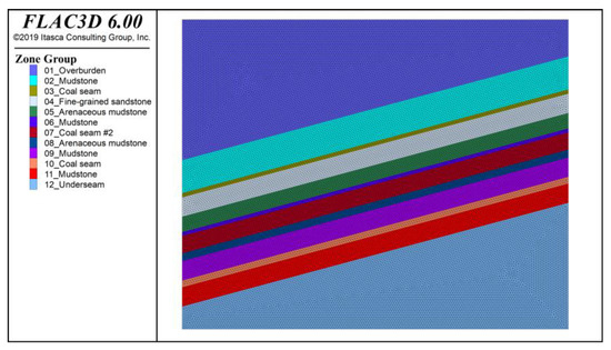
Figure 9.
Numerical calculation model.
- (2)
- Numerical simulation scheme design
Meeting the actual demand on-site is challenging due to the large deformation of the surrounding rock in the original support scheme of the tested roadway. Therefore, this numerical simulation optimization scheme, based on the original support scheme, considered changing the roadway shape, the bolt size and the spacing between rows, and the type of anchor cables. Therefore, six simulation schemes were designed, as shown in Table 4.
Table 4.
Numerical simulation schemes.
- (3)
- Determine the optimization program and benefit estimate
Figure 10 and Figure 11 show the simulation results. The observation points of displacement and deformation were set on the left side, right side, roof, and floor of the roadway model to analyze the deformation of the surrounding rock of the roadway with different support schemes. Figure 11 shows the deformation curve of the surrounding rock of the roadway (upward and right directions of displacement deformation are positive; downward and left directions are negative).
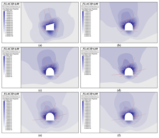
Figure 10.
Deformation nephogram of roadway surrounding rock. (a) The original support scheme. (b) Optimization scheme I. (c) Optimization scheme II. (d) Optimization scheme III. (e) Optimization scheme IV. (f) Optimization scheme V.
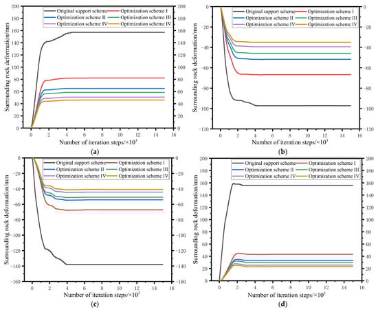
Figure 11.
Deformation curve of roadway surrounding rock. (a) Left side of the roadway. (b) Right side of the roadway. (c) Roadway roof. (d) Roadway floor.
According to the analysis of the simulation results, when the original support scheme is adopted, the roadway deformation is large and the maximum deformation of the left side, right side, roof, and floor reaches 157, −97, −138, and 158 mm respectively. The simulation results of schemes I–IV show that the deformation of the surrounding rock declines with increased roadway support strength. Moreover, schemes III–V show that when the support strength increases past a certain point, the deformation of the surrounding rock of the roadway does not change significantly. Considering the support cost of the roadway, optimization scheme IV was preliminarily selected for the tested roadway with relatively small roadway deformation. The maximum deformation of the left side, right side, roof, and floor of the roadway was predicted to be 51, −39, −45, and 28 mm, respectively.
The tested working face with a length of 1200 m was taken as an example. If all the optimized support schemes are adopted, the economic benefits are estimated as follows: (1) compared with the optimized support schemes, the roadway support costs will increase by 1.2 million yuan; (2) the maintenance cost of the roadway is reduced by 760,000 yuan; (3) smooth stopping at the working face is expected to increase annual output by 70,000 tons and economic benefits by 49 million yuan. Based on the above analysis, the overall economic benefit is estimated be 48.56 million yuan after adopting the optimized support scheme.
5.2. Optimized Support Scheme Design
Since changing the excavation azimuths of the roadway has a great influence on the production system of the whole mining area, combined with the actual situation of Zijin Coal mine, the optimal design of the deformation control scheme of the surrounding rock of the tested roadway only considers two aspects: the shape of the roadway section and the support scheme. According to the geological conditions of the Zijin Coal Mine, the effectiveness analysis of the original support scheme of the tested roadway, the analysis of the simulation results, and the geostress survey results, optimization scheme IV with H-G anchor cables, high strength bolt, W-shaped steel belts, metal meshes, and sprayed concretes was selected, and the shape of the tested roadway was changed to an arch section. The roof of the roadway was designed as a semicircular arch, while the floor was designed as a reverse arch (Figure 12). Specific supporting parameters are as follows:
- (1)
- The arch section of the upper part of the roadway adopts seven high-strength and high-pretension bolts, which are arranged in the shape of five flowers. Moreover, M4 steel belts and 4–6 mm wire meshes were used for combined support. The anchor-bolt specification is Φ22 × 2400 mm. Each bolt consists of one CK2370 fast bolt and one Z2370 medium-speed resin coil for full-length anchoring, and pretension is not less than 7 tons. The bolt inter-row spacing is 700 × 700 mm;
- (2)
- Six high-strength and high-pretension bolts are used on both roadway sides. M4 steel belts and 4–6 mm wire meshes are used for combined support. The anchor bolt specification is Φ20 × 2400 mm, and other parameters are the same as the roof bolt;
- (3)
- Two strong pretension H-G anchor cables are installed in the roadway vault. The anchor cable specification is Φ24.6 × 7000 mm. The full-length anchoring method is adopted and each anchor cable is anchored by one CK2370 fast resin coil. Preload is not less than 7 tons. Anchor-cable grouting can be performed as soon as possible under without affecting the excavation. The anchor-cable tray is circular with a diameter of 250 mm and a thickness of not less than 4 mm. The cable row spacing is 1400 mm;
- (4)
- A strong pretension H-G anchor cable is installed on each side of the roadway. The H-G anchor cable specification is Φ24.6 × 6000 mm. The H-G anchor cable is arranged in the middle of the coal seam and arranged along the coal-seam tendency. Other parameters are the same as the roof anchor cable. High pressure of 5 MPa is used to inject mud into the anchor cable to increase the strength of anchor-cable grouting. As the coal rock mass is broken, the grouting volume needs to be increased until the grout cannot be injected at high pressure;
- (5)
- The reverse arch of the roadway floor is filled with concrete material. The whole section of the roadway includes a flexible concrete spray layer with a thickness of 100 mm. The materials are general silicon no. 425, medium-coarse sand, and 2–4-mm stone. The material ratio is according to the volume ratio; the cement:sand:stone ratio is 1:2:2. The content of the accelerant is 4% of the cement dosage. The softening agents are steel fibers or high-elastic vinylon fibers (with a diameter of 10–25 m and a length of 15–25 mm). The dosage of the softening agent is 0.5% of the cement weight. The concrete shotcrete layer on both sides of the roadway should be implemented immediately if site conditions permit it after the roadway is evacuated to reduce the weathering of rock and coal sides.

Figure 12.
Section diagram of the optimal support scheme design of the tested roadway (unit: mm).
5.3. Selection of New H-G Anchor Cables
The application of the new H-G anchor cable is important for the optimal support of the tested roadway. The H-G anchor cable [36,37,38,39] is mainly composed of an anchor cable, face plate, cordage, and stop-grouting plug parts. The anchor cable is made of prestressed spiral-ribbed high-strength steel wire, which gives the new H-G anchor cable a greater supporting effect. The new H-G anchor cable was developed by the Shandong Jinan Aoke Company [36,37,38,39]. Compared with cable cut by conventional steel strand, the load transfer characteristics, anchorage strength, and anchorage ductility of the new H-G anchor cable are greatly improved.
The technical parameters of the new H-G anchor cable are as follows: the nominal diameter of the steel wire is 6.0 mm; the diameter of the anchor cable body is 24.6 mm; the length of the roof anchor cable is 7000 mm; the length of two sides roadway anchor cable is 6000 mm; the installation aperture is 32 mm; strength is 1760 Mpa; breaking force is greater than 420 KN; the resin anchoring length is 1000–1500 mm. The specifications of the H-G pipe are as follows: an inner diameter of 7.5 mm, an outer diameter of 10 mm, and a grouting pressure greater than 5.0 MPa. Figure 13a,b present the H-G anchor cable and the field installation, respectively.
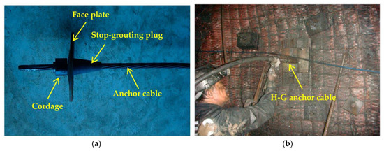
Figure 13.
H-G anchor cable. (a) Physical picture. (b) Site installation drawing.
Chemical grout, cement single slurry, sodium silicate, cement mixed double slurry, and new high-water fast-setting materials are commonly used in China. The grouting materials of the H-G anchor cable in the coal mine are composite cement grouts specially matched by the original manufacturer of H-G anchor cable. The cement is no. 525, and the water-cement ratio is 1:2. ACZ-I cement grouting additive is added at a proportion of 8%.
6. Field Application Effect Analysis
6.1. Scheme Design Observing the Tested Roadway
The total length of the 3201 material roadway is about 1200 m. The optimized support scheme was adopted within 100 m behind the roadway after the roadway is excavated for about 600 m. At present, the roadway construction has been completed. The displacement and stress of surrounding rock were monitored to analyze the effect of the optimized support scheme. Four monitoring stations were arranged in the tested roadway (see Figure 14). Monitoring stations 1 and 2 were arranged in the roadway section with the original support scheme, and monitoring stations 3 and 4 were arranged in the roadway section with the optimized support scheme. The distance between measuring stations 2 and 3 was about 400 m, that between 1 and 2 was 10 m, and that between 3 and 4 was 10 m.
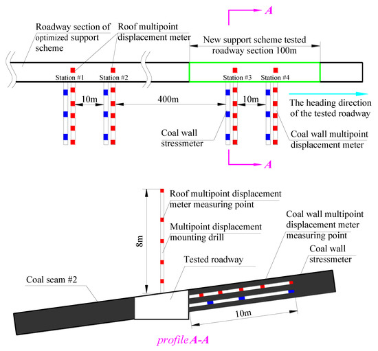
Figure 14.
Layout of monitoring stations in the tested roadway.
Displacement meters and stress meters were installed at measuring stations 1 and 4, 10 m away from the roadway head to compare the initial deformation of the tested roadway after excavation using different support methods. Displacement meters and stress meters were installed at measuring stations 2 and 3, 0.5 m away from the roadway head.
Each monitoring station was equipped with one displacement meter for the roof and one displacement meter for the coal sides (see Figure 15).The GEL multipoint displacement meter widely used in Australia was applied for displacement monitoring. The displacement meters have five measuring points, and the measuring range is generally 100 mm; the measuring range can be increased to 300 mm for special needs. Measuring accuracy is 0.5 mm. The displacement meters can be installed in holes with a diameter of 27–55 mm. Each monitoring station was equipped with three stress meters (installed in the same borehole) for coal sides (see Figure 15). Vibration string stress meters made by GEOKON in the United States were adopted due to the advantages of high accuracy (0.07 MPa) and good stability.
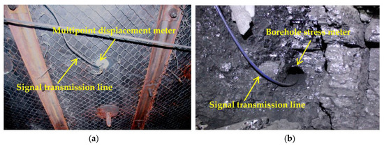
Figure 15.
Site installation of displacement meter and stress meter in the tested roadway. (a) Site installation of multipoint displacement meter on roof. (b) Site installation diagram of stress gauge on roadway sides.
6.2. Analysis of the Field Application Effect
Figure 16, Figure 17, Figure 18 and Figure 19 show the monitoring results of the displacement meters and stress meters at each monitoring station.
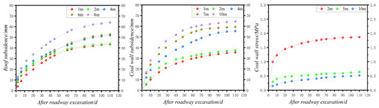
Figure 16.
Monitoring results of station 1.
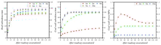
Figure 17.
Monitoring results of station 2.
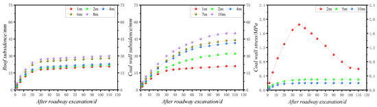
Figure 18.
Monitoring results of station 3.
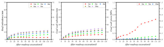
Figure 19.
Monitoring results of station 4.
According to the analysis of the monitoring results of the four stations, (1) the deformations of the roadway roof and coal sides were large for stations 1 and 2 in the tested roadway sections with the original support scheme. The roadway advanced about 70 m, and the monitoring of station 2 showed that the total deformation of the roadway surrounding rock exceeded 100 mm (beyond the range of displacement meter) two weeks after the installation. Measuring stations 3 and 4 were located in the tested roadway section with the optimized support scheme, where deformations of the roadway roof and floor were much smaller. The roadway advanced about 50 m. The total deformation of the surrounding rock was less than 50 mm two weeks after the installation, which was more than 50% less than that of the original support scheme. (2) The displacement meter values of measuring stations 2 and 3 were more than twice as large as those of measuring stations 1 and 4 at the initial tested-roadway excavation, indicating that the initial deformation of the tested roadway was large after the excavation. Anchor bolts and cables should be installed immediately after roadway excavation to reduce the initial deformation of the roadway. (3) Vertical stress at 2 m depth of coal sides was larger, while the stress at 5 and 10 m depth was smaller, indicating that the range of loose circles of coal sides should be between 2 and 5 m.
7. Conclusions
- (1)
- Five measuring points were arranged to survey geostress in the Zijin Coal Mine—three in the 3201 working face and two in the west wing air-return main roadway. Measuring points were arranged in the roof and floor strata of coal seam 2. The survey results showed that the geostress of the coal mine was high, and horizontal stress was generally greater than vertical stress. Maximum horizontal principal stress was about 18 MPa, which was 1.13–2.20 times greater than vertical stress. The geostress of the coal mine is mainly horizontal stress, and the direction of horizontal stress is 56–95°. As a result, the stability of the underground roadway is mainly affected by high horizontal stress.
- (2)
- According to the actual situation of Zijin Coal Mine with high horizontal geostress and three-soft coal roadways, a new optimized support scheme using H-G anchor cables, high-strength bolts, W-shaped steel belts, metal meshes, and sprayed concretes was proposed. The scheme had the following characteristics: the shape of the tested roadway was changed into an arch section; the roof of the roadway was designed as a semicircular arch, while the floor was designed as a reverse arch; the strength and support density of bolts and cables in the roof and coal sides were increased; roof and coal side anchor cables were added, and new grouting anchor cables were used to perform full-length anchoring. All bolts and cables were installed with a high preload, and all were anchored at full length.
- (3)
- After the optimized support scheme was adopted in the tested roadway, the field monitoring results showed that the 100 m tested roadway with the optimized support scheme was completely formed after excavation. There was no obvious damage to roof, floor, or coal sides. Compared with the original support scheme, the stability of the tested roadway was improved. The displacement of roadway roof decreased from 100 to 30 mm in the optimized support scheme section, and the displacement of the coal sides decreased from more than 100 mm to less than 50 mm.
Author Contributions
Conceptualization, X.X. and H.L.; methodology, X.F.; software, X.X.; validation, J.Y., J.L. and M.L.; formal analysis, G.W.; investigation, H.L.; resources, J.Y.; data curation, X.F.; writing—original draft preparation, X.X.; writing—review and editing, H.L.; visualization, X.F.; supervision, J.L.; project administration, X.F.; funding acquisition, J.Y. All authors have read and agreed to the published version of the manuscript.
Funding
This work was supported by the Liupanshui Normal University fund (LPSSYYBZK202202, LPSSYjg-2021-34), the Science and Technology Department of Guizhou Province Fund (Qiankehe Platform Talent-YSZ [2021] 001), the Education Department of Guizhou Province Fund (Qianjiaohe KY Zi [2020] 050, Qianjiaohe [2020] 122, Qianjiao XKTJ [2020] 23), and the Liupanshui Science and Technology Bureau Fund (52020-2022-PT-15).
Data Availability Statement
Some or all data, models, or codes generated or used during the study are available from the corresponding author upon request.
Acknowledgments
The authors would like to thank the Mining Engineering Laboratory of School of Mining and Mechanical Engineering of Liupanshui Normal University for its rock mechanics experimental support and the support of the field test in the Zijin Coal Mine in Shanxi Province. The authors are grateful to the reviewers for carefully reading the manuscript and providing valuable suggestions.
Conflicts of Interest
The authors declare no conflict of interest.
References
- Wang, P.; Su, X.; Han, Y.; Fan, C.; Zhang, Y. Quantitative Characterization of Coal structure and its significance. Saf. Coal. Min. 2014, 26, 12–15. [Google Scholar]
- Yu, S.; Wang, S.; Li, J.; Chen, X.; Chen, L.; Dong, Q.; Zhang, X.; Huang, P. Massive Hydraulic Fracturing to Control Gas Outbursts in Soft Coal Seams. Rock Mech. Rock Eng. 2022, 17, 1759–1776. [Google Scholar]
- Wu, J.; Zhang, G. Research on Development Characteristics of Micro-Fractures in a Soft Coal Seam Based on the Water-Injection Effect. Chem. Technol. Fuels Oils. 2020, 26, 312–324. [Google Scholar]
- Yang, R.S.; Li, Y.L.; Guo, D.M.; Yao, L.; Yang, T.M.; Li, T.T. Failure mechanism and control technology of water-immersed roadway in high-stress and soft rock in a deep mine. Int. J. Min. Sci. Technol. 2017, 27, 245–252. [Google Scholar] [CrossRef]
- Yu, H.; Jia, H.; Liu, S.; Li, B. Macro and micro grouting process and the influence mechanism of cracks in soft coal seam. Nt. J. Coal. Sci. Technol. 2021, 8, 969–982. [Google Scholar] [CrossRef]
- Yang, S.; Wen, G.; Yan, F.; Zhang, M.; Zhao, X. Evaluating the maximum rate of penetration for drilling borehole in soft coal seam. Energ. Sci. Eng. 2020, 8, 3273–3284. [Google Scholar] [CrossRef]
- Li, H.; Wang, W.; Liu, Y.; Ma, W.; Gao, H. An integrated drilling, protection and sealing technology for improving the gas drainage effect in soft coal seams. Energ. Rep. 2020, 6, 2030–2043. [Google Scholar] [CrossRef]
- Kang, X.; Guo, D.; Lu, Z. Mechanism of Roadway Floor Heave Controlled by Floor Corner Pile in Deep Roadway under High Horizontal Stress. Adv. Civ. Eng. 2021, 2021, 6669233. [Google Scholar] [CrossRef]
- Christopher, M.; Michael, G. Pillar design and coal burst experience in Utah Book Cliffs longwall operations. Int. J. Min. Sci. Technol. 2021, 31, 33–41. [Google Scholar]
- Yao, J.; Xu, Z.; Wang, J.; Wang, L. Experimental study on rock burst control with bolt-aluminum foam combined support. Rock. Soil. Mech. 2021, 42, 620–626. [Google Scholar]
- Xie, H.P.; Gao, M.Z.; Zhang, R.; Peng, G.Y.; Wang, W.Y.; Li, A.Q. Study on the Mechanical Properties and Mechanical Response of Coal Mining at 1000m or Deeper. Rock Mech. Rock. Eng. 2019, 52, 1475–1490. [Google Scholar] [CrossRef]
- Xie, L.; Yan, P.; Lu, W.; Chen, M.; Wang, H. Efects of strain energy adjustment: A case study of rock failure modes during deep tunnel excavation with difffferent methods. Ksce. J. Civ. Eng. 2018, 10, 4143–4154. [Google Scholar] [CrossRef]
- Jiang, Y.; Zhao, Y. State of the art: Investigation on mechanism, forecast and control of coal bumps in China. J. Rock Mech. Geotech. Eng. 2015, 34, 2188–2204. [Google Scholar]
- Kang, C. Key technologies for surrounding rock control in deep roadway. J. China Univ. Min. Technol. 2017, 46, 1071–1081. [Google Scholar]
- Kang, H. Sixty years development and prospects of rock bolting technology for underground coal mine roadways. J. China Univ. Min. Technol. 2016, 45, 1071–1081. [Google Scholar]
- He, M. Progress and challenges of soft rock engineering in depth. J. China Univ. Min. Technol. 2014, 39, 1409–1417. [Google Scholar]
- Gao, Y.; Wang, B.; Wang, J. Test on structural property and application of concrete-fifilled steel tube support of deep mine and soft rock roadway. Chin. J. Rock Mech. Eng. 2010, 29, 1409–1417. [Google Scholar]
- Kang, H.; Wang, J.; Lin, J. Case study of rock bolting in coal mine roadways. Chin. J. Rock Mech. Eng. 2010, 29, 649–664. [Google Scholar]
- Yang, J.; Shi, H.; Gan, Q.I. Research on mechanism for flfloor heave control in the roadway by base-angel-bolt and its type selection test. J. China Coal Soc. 2016, 33, 643–648. [Google Scholar]
- He, F.; Zhang, G. Stability analysis and control of deep under ground road ways subjected to high horizontal tectonic stess. J. China Univ. Min. Technol. 2015, 44, 466–476. [Google Scholar]
- Kang, H.; Yi, B.; Gao, F.; Lv, H. Database and characteristics of underground in-situ stress distribution in Chinese coal mines. J. China Coal Soc. 2019, 44, 23–33. [Google Scholar]
- Zhang, S.; Li, J.; Ma, J. Roadway Supporting Technology Applied to Three Soft Coal Seam at Yanlong Mining Area in China. Therm. Sci. 2019, 23, 887–895. [Google Scholar] [CrossRef]
- Li, X.; Yao, Q.; Zhang, N.; Wang, D.; Zhen, X.; Ding, X. Numerical Simulation of Stability of Surrounding Rock in High Horizontal Stress Roadway Under Overhead Mining. J. Min. Saf. Eng. 2008, 25, 420–425. [Google Scholar]
- Li, W.; Liu, J.; Chen, L.; Zhong, Z.; Liu, Y. Roadway Support in Deep "Three-Soft" Coal Seam: A Case Study in Yili Mining Area, China. Shock. Vib. 2021, 18, 8851057. [Google Scholar] [CrossRef]
- Zhang, H.; Han, L.; He, N. Floor heave control in roadways with soft-and-swelling rocks in complicated structural area. J. Min. Saf. Eng. 2011, 28, 16–27. [Google Scholar]
- Zhang, W.; He, Z.; Qi, D.; Zhang, W.; Zhang, d. Surrounding rock deformation control of asymmetrical roadway in deep three-soft coal seam: A case study. J. Geophys. Eng. 2018, 15, 1917–1928. [Google Scholar] [CrossRef]
- Shen, J.; Zhang, Y. Theory and Application of Gob-Side Entry Retaining in Thick Three-Soft Coal Seam. Geofluids 2021, 2, 6157174. [Google Scholar] [CrossRef]
- Guo, D.; Kang, X.; Lu, Z.; Chen, Q. Mechanism and Control of Roadway Floor Rock Burst Induced by High Horizontal Stress. Shock. Vib. 2021, 5, 6745930. [Google Scholar] [CrossRef]
- Chen, D.; Yuan, Y.; Ma, L. Deformation and Failure Characteristics and Control Technology of Surrounding Rocks in Deep High-Horizontal Stress Rock Roadways in the Wanbei Mining Area. Front. Earth Sci Prc. 2022, 10, 886221. [Google Scholar] [CrossRef]
- Yuan, Y.; Wang, W.; Li, S.; Zhu, Y. Failure Mechanism for Surrounding Rock of Deep Circular Roadway in Coal Mine Based on Mining-Induced Plastic Zone. Adv. Civ. Eng. 2018, 2018, 1835381. [Google Scholar] [CrossRef]
- Sun, Y.; Li, G.; Zhang, J.; Qian, D. Stability Control for the Rheological Roadway by a Novel High-Efficiency Jet Grouting Technique in Deep Underground Coal Mines. Sustainability 2019, 11, 6494. [Google Scholar] [CrossRef]
- Yang, S.; Chen, M.; Jing, H.; Chen, K.; Meng, B. A case study on large deformation failure mechanism of deep soft rock roadway in Xin’An coal mine, China. Eng. Geol. 2017, 217, 89–101. [Google Scholar] [CrossRef]
- Wang, Q.; Pan, R.; Jiang, B.; Li, S.; He, M.; Sun, H.; Wang, L.; Qin, Q.; Yu, H.; Luan, Y. Study on failure mechanism of roadway with soft rock in deep coal mine and confined concrete support system. Eng. Fail. Anal. 2017, 81, 155–177. [Google Scholar] [CrossRef]
- Shreedharan, S.; Kulatilake, P. Discontinuum-Equivalent Continuum Analysis of the Stability of Tunnels in a Deep Coal Mine Using the Distinct Element Method. Rock Mech. Rock Eng. 2016, 49, 1903–1922. [Google Scholar] [CrossRef]
- Zhai, X.; Huang, G.; Chen, C.; Li, R. Combined Supporting Technology with Bolt-Grouting and Floor Pressure-Relief for Deep Chamber: An Underground Coal Mine Case Study. Energies 2018, 11, 67. [Google Scholar] [CrossRef]
- Szurgacz, D.; Brodny, J. Tests of Geometry of the Powered Roof Support Section. Energies 2019, 12, 3945. [Google Scholar] [CrossRef]
- Szurgacz, D.; Brodny, J. Adapting the Powered Roof Support to Diverse Mining and Geological Conditions. Energies 2020, 13, 405. [Google Scholar] [CrossRef]
- He, M.; Gao, Y.; Yang, J.; Gong, W. An Innovative Approach for Gob-Side Entry Retaining in Thick Coal Seam Longwall Mining. Energies 2017, 10, 1785. [Google Scholar] [CrossRef]
- Liu, S.; Zhang, W.; Feng, Y. Study on migration mechanism of slipping floor heave rock mass in deep roadway and its control countermeasure. J. China Coal Soc. 2013, 30, 706–711. [Google Scholar]
Disclaimer/Publisher’s Note: The statements, opinions and data contained in all publications are solely those of the individual author(s) and contributor(s) and not of MDPI and/or the editor(s). MDPI and/or the editor(s) disclaim responsibility for any injury to people or property resulting from any ideas, methods, instructions or products referred to in the content. |
© 2023 by the authors. Licensee MDPI, Basel, Switzerland. This article is an open access article distributed under the terms and conditions of the Creative Commons Attribution (CC BY) license (https://creativecommons.org/licenses/by/4.0/).