
Analysis and Impacts of Grid Integrated Photo-Voltaic and Electric Vehicle on Power Quality Issues

 ,
,  ,
,  and
and
Abstract
:1. Introduction
2. Literature Review
3. Research Gap
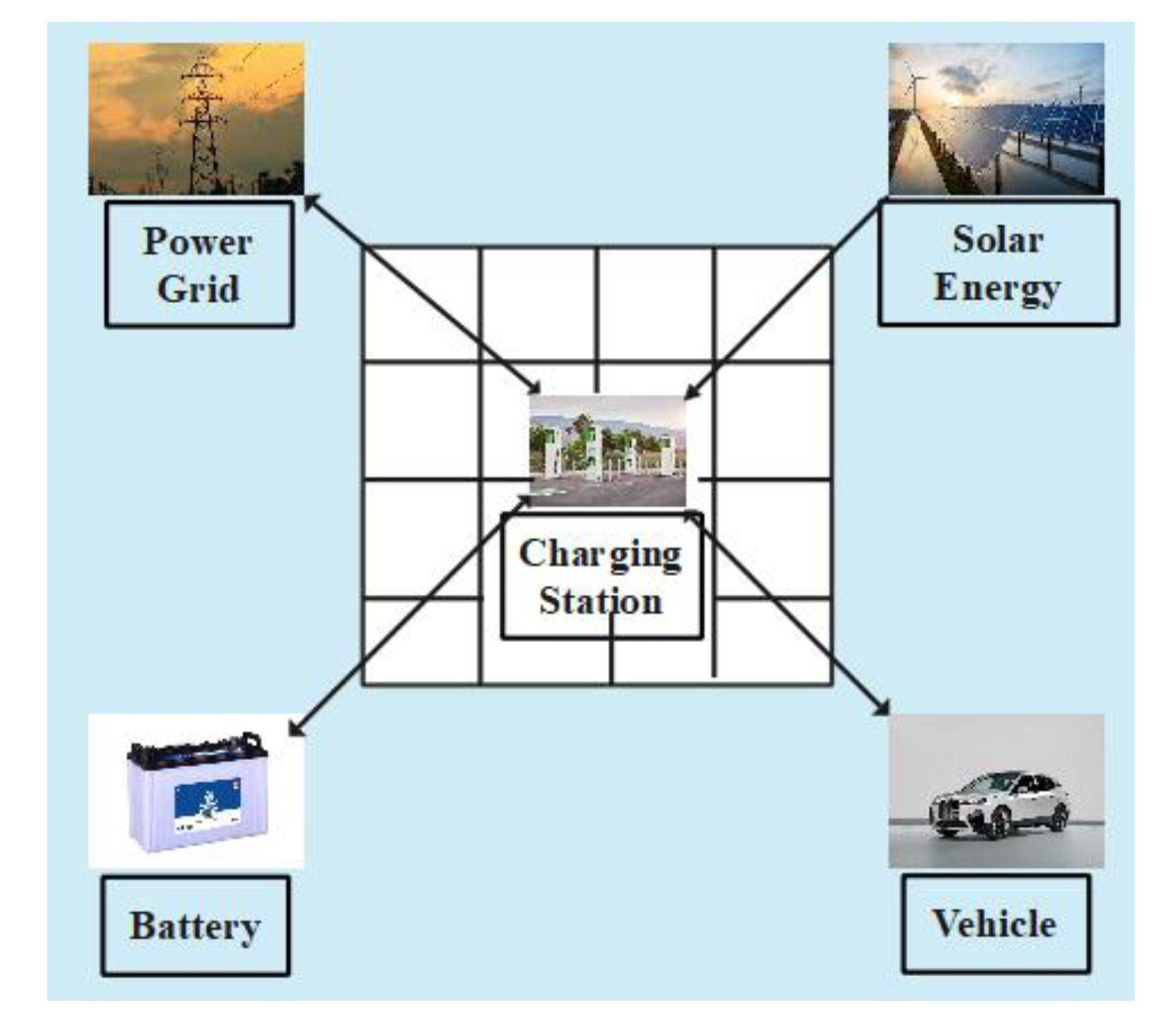
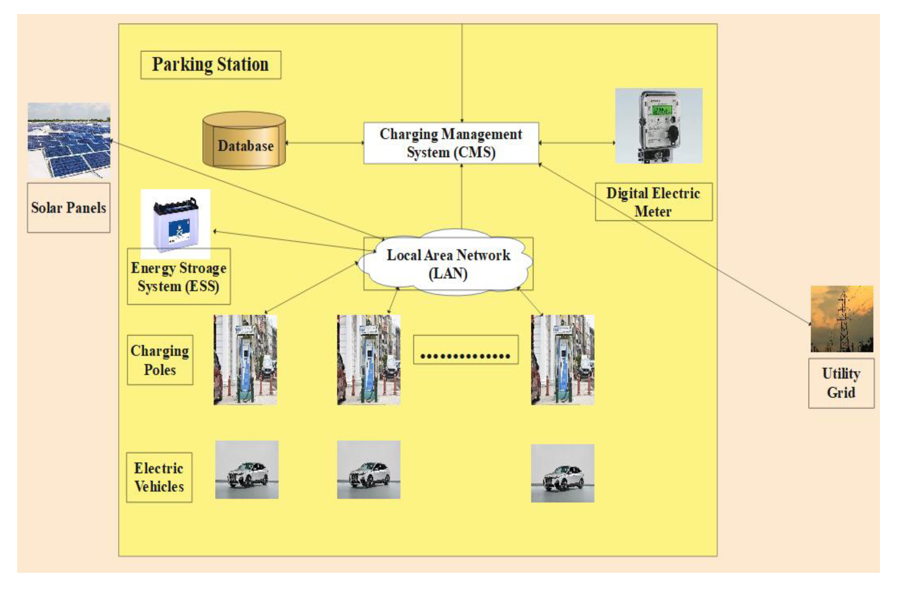
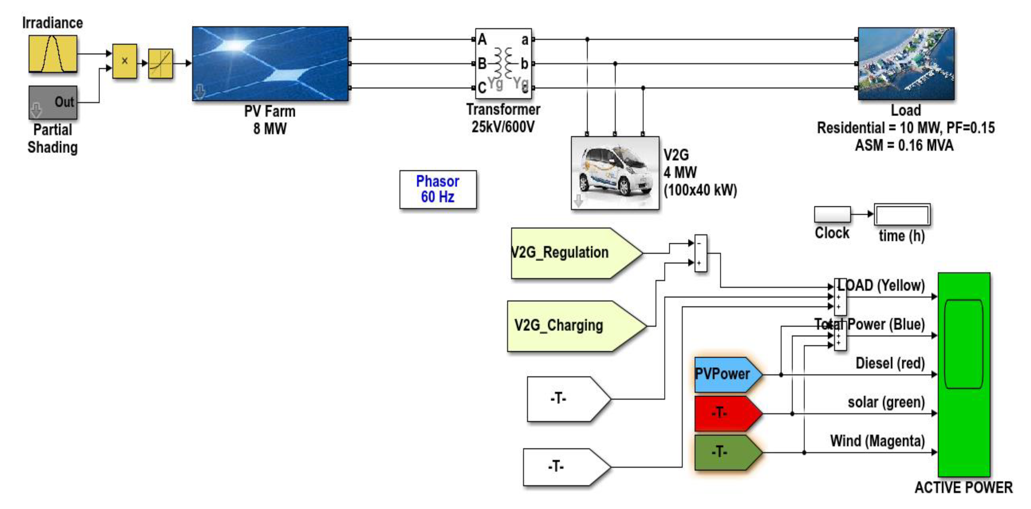
4. Brief Overview of PV-Grid-EV
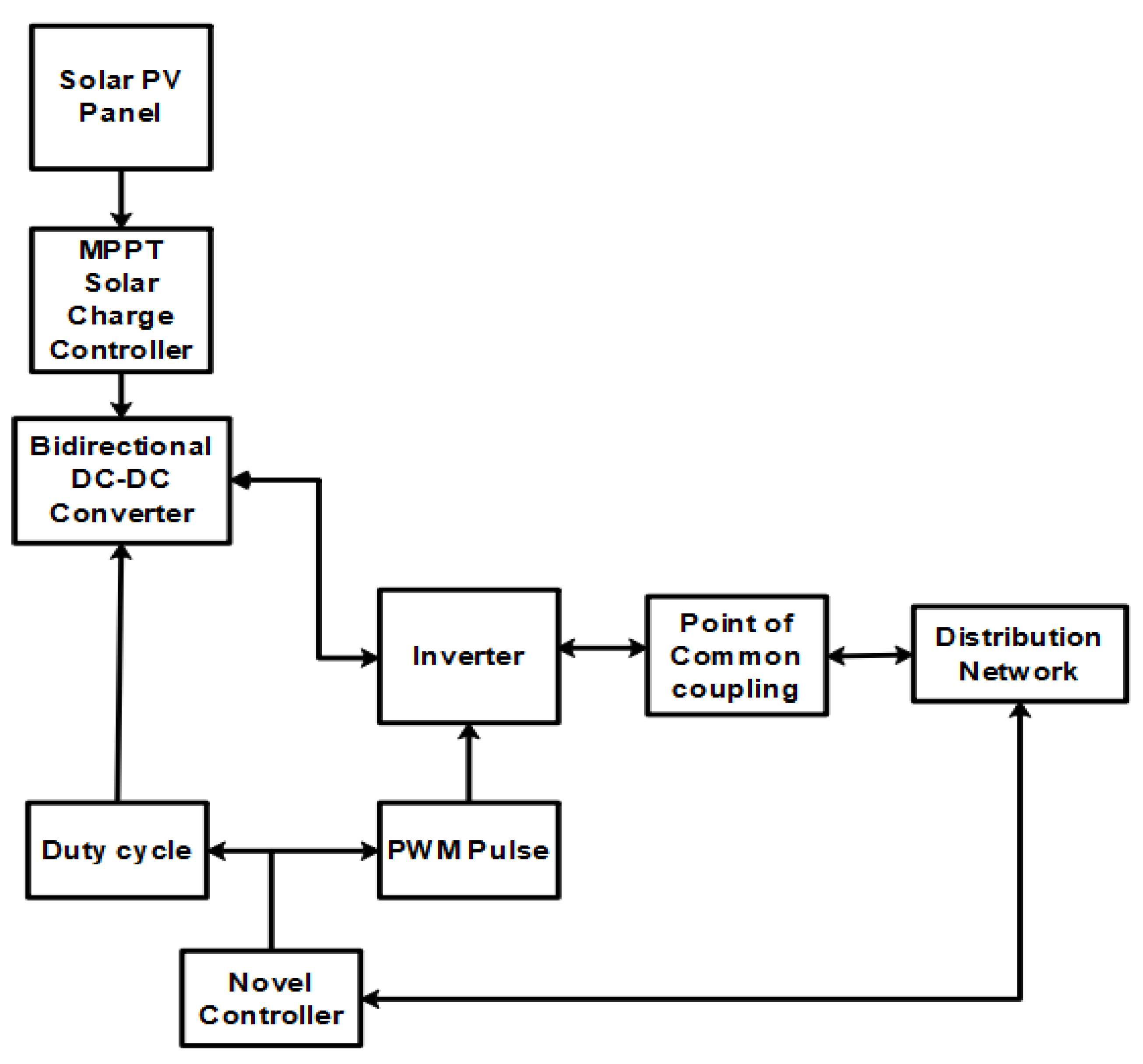
4.1. 1st Module (PV-to-Grid)
- Initially, PV produces the power, which completely depends upon the irradiation and temperature. Furthermore, MPPT tracking is used to extract the maximum power from the PV panel.
- The power is extracted from the PV, which is given as the input to the bidirectional DC-DC converter.
- This converter improves the voltage level up to a certain level, which depends on the specification. The main theme of the converter is to stabilize the value.
- The improvement in voltage completely depends on the duty cycle ratio, which is decided by our controller.
- After receiving the stabilized value from the converter, which is given as an input to the inverter, the main purpose of the inverter is to convert DC to AC.
- After this conversion, it is connected to the grid through a point of common coupling.
- The controller side plays a major role in this work.
- The controller is going to decide the power flow by calculating the load demand. Once the power flow is done, the controller calculates the load demand, and it will trigger the switches as well as produce a proper duty cycle ratio to control the load demand.
- The major impact in this scenario will be error harmonics—which will be produced on the load side—as well as power factor issues, voltage sag/swell, flickering, and the cost.
- On the solar side, the major impact will be loose connections, birds, roof issues, and potential-induced degradation.
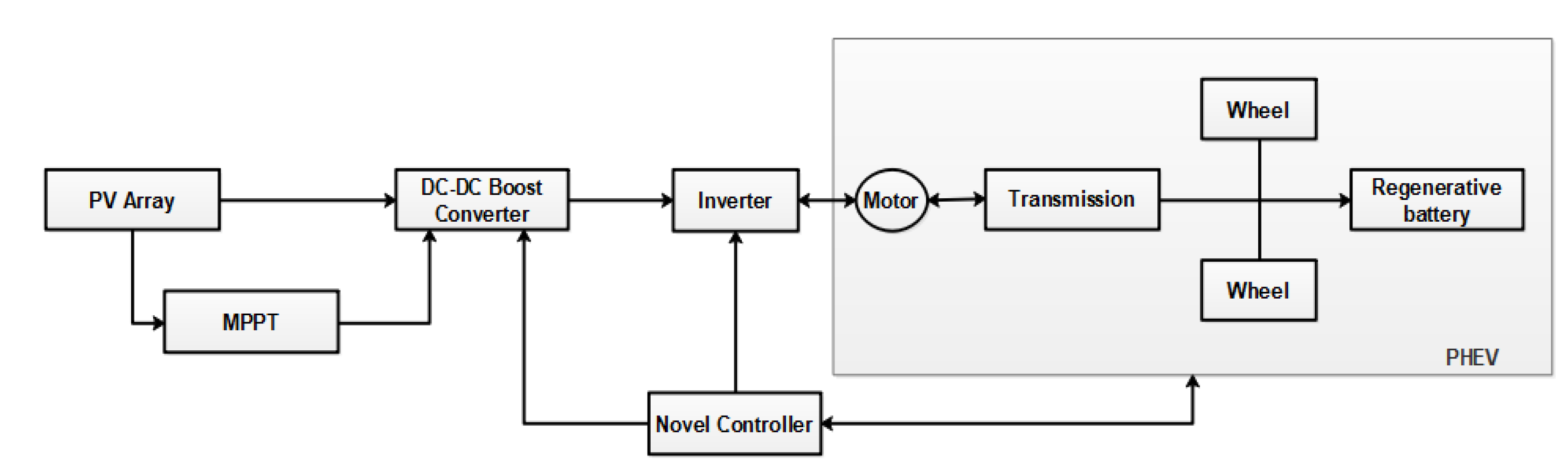
4.2. 2nd Module (PV-to-Vehicle)
- Initially, PV produces the power, which completely depends upon the irradiation and temperature. Furthermore, MPPT tracking is used to extract the maximum power from the PV panel.
- The power is extracted from the PV, which is given as an input to the bidirectional DC-DC converter.
- This converter improves the voltage level up to a certain level, which depends on the specification. The main theme of the converter is to stabilize the value.
- The improvement in voltage completely depends on the duty cycle ratio, which is decided by our controller.
- After receiving the stabilized value from the converter, which is given as an input to the inverter, the main purpose of the inverter is to convert DC to AC.
- After this conversion, it is connected to the load, which is the EV.
- Same as the above, the controller will calculate the EV demand and produce the proper duty cycle as well as pulse to trigger the switches.
- Here, the major impact on the EV side is speed regulation, driving range, battery efficiency, state of charge, infrastructure (roads).
4.3. 3rd Module (PV-to-Grid-to-Vehicle)
- Initially, PV produces the power, which completely depends upon the irradiation and temperature. Furthermore, MPPT tracking is used to extract the maximum power from the PV panel.
- The power is extracted from the PV, which is given as the input to the bidirectional DC-DC converter.
- This converter improves the voltage level up to a certain level, which depends on the specification. The main theme of the converter is to stabilize the value.
- The improvement in voltage completely depends on the duty cycle ratio, which is decided by our controller.
- After receiving the stabilized value from the converter, the algorithm will check the load demand and distribute mutual power to both the grid and vehicle.
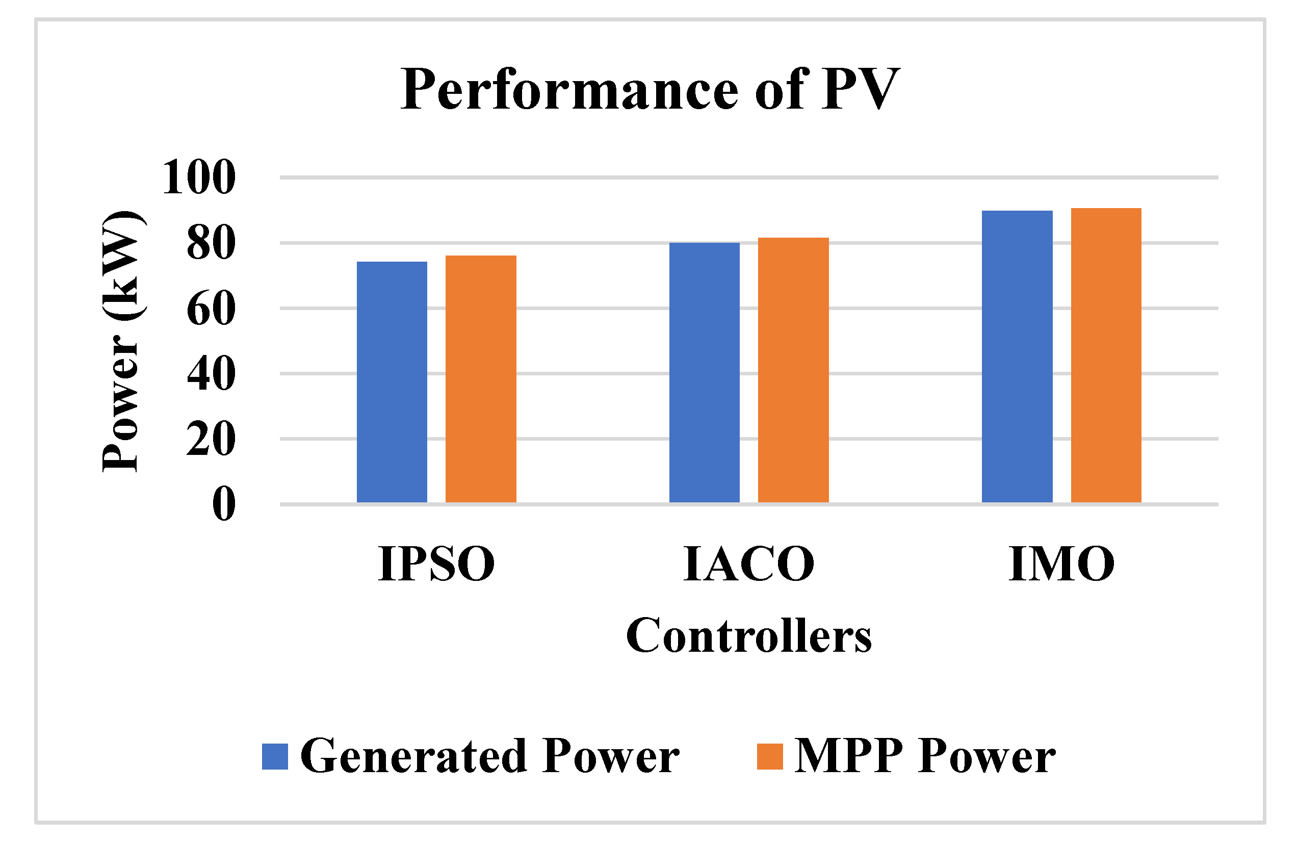
- The following are the methods that are used for the analysis, they are, IPSO, IACO and IMO. Those controllers follow the above-mentioned process and produces better results which is described in the upcoming section.
5. Methodological Analysis
5.1. Improved Particle Swarm Optimization (IPSO)
5.2. Improved Ant Colony Optimization (IACO)
5.3. Improved Mayfly Optimization (IMO)
6. Results and Discussion
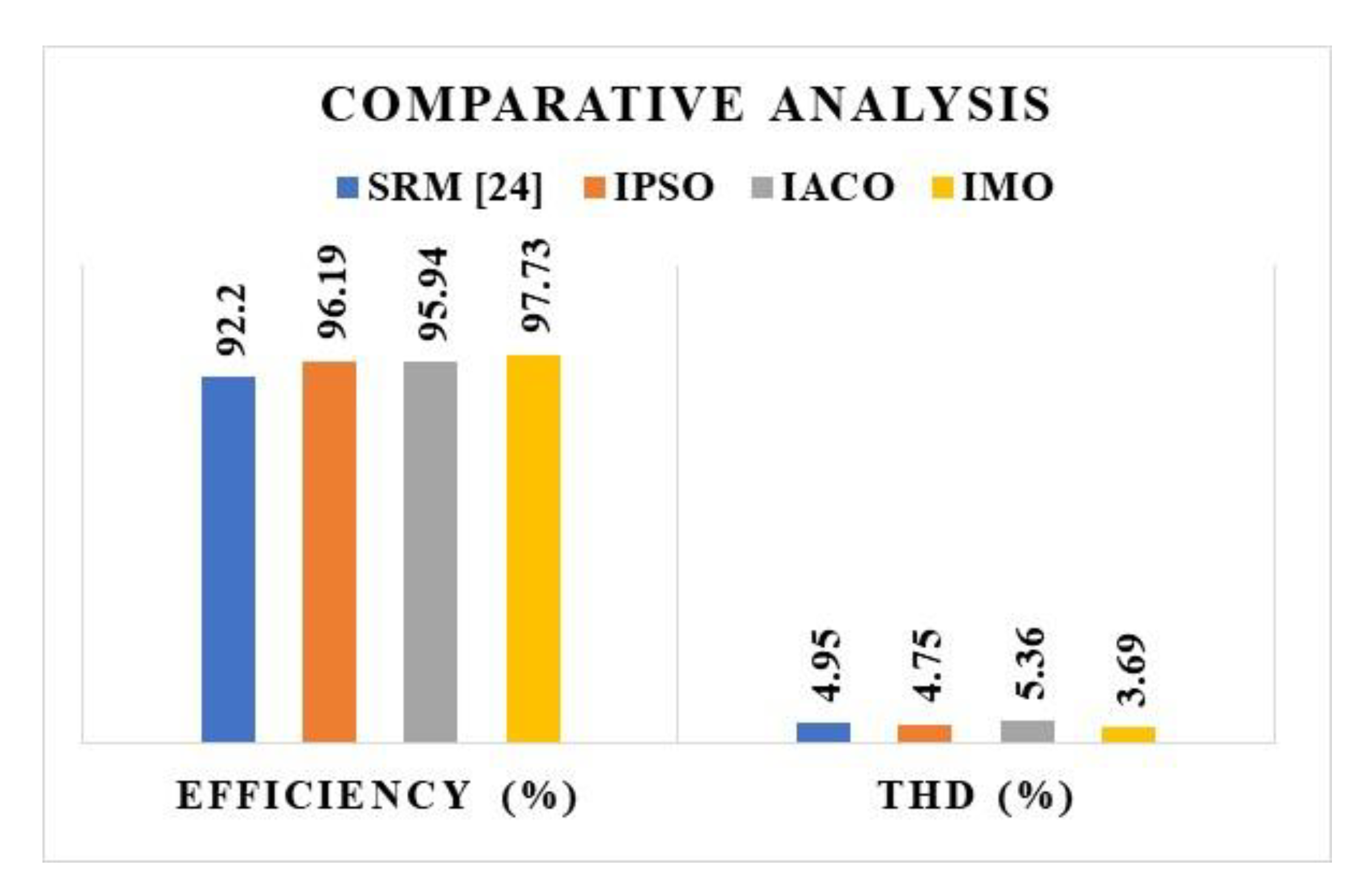
Comparative Analysis
7. Conclusions
Author Contributions
Funding
Institutional Review Board Statement
Informed Consent Statement
Data Availability Statement
Conflicts of Interest
References
- Hemmati, R.; Mehrjerdi, H. Investment deferral by optimal utilizing vehicle to grid in solar powered active distribution networks. J. Energy Storage 2020, 30, 101512. [Google Scholar] [CrossRef]
- Sangswang, A.; Konghirun, M. Optimal strategies in home energy management system integrating solar power, energy storage, and vehicle-to-grid for grid support and energy efficiency. IEEE Trans. Ind. Appl. 2020, 56, 5716–5728. [Google Scholar] [CrossRef]
- Mehrjerdi, H.; Rakhshani, E. Vehicle-to-grid technology for cost reduction and uncertainty management integrated with solar power. J. Clean. Prod. 2019, 229, 463–469. [Google Scholar] [CrossRef]
- Uddin, K.; Dubarry, M.; Glick, M.B. The viability of vehicle-to-grid operations from a battery technology and policy perspective. Energy Policy 2018, 113, 342–347. [Google Scholar] [CrossRef]
- Amamra, S.A.; Marco, J. Vehicle-to-grid aggregator to support power grid and reduce electric vehicle charging cost. IEEE Access 2019, 7, 178528–178538. [Google Scholar] [CrossRef]
- Heilmann, C.; Friedl, G. Factors influencing the economic success of grid-to-vehicle and vehicle-to-grid applications—A review and meta-analysis. Renew. Sustain. Energy Rev. 2021, 145, 111115. [Google Scholar] [CrossRef]
- Iacobucci, R.; McLellan, B.; Tezuka, T. Optimization of shared autonomous electric vehicles operations with charge scheduling and vehicle-to-grid. Transp. Res. Part C Emerg. Technol. 2019, 100, 34–52. [Google Scholar] [CrossRef]
- Alsharif, A.; Tan, C.W.; Ayop, R.; Dobi, A.; Lau, K.Y. A comprehensive review of energy management strategy in Vehicle-to-Grid technology integrated with renewable energy sources. Sustain. Energy Technol. Assess. 2021, 47, 101439. [Google Scholar] [CrossRef]
- Brenna, M.; Foiadelli, F.; Leone, C.; Longo, M. Electric vehicles charging technology review and optimal size estimation. J. Electr. Eng. Technol. 2020, 15, 2539–2552. [Google Scholar] [CrossRef]
- Letha, S.S.; Bollen, M. Impact of Electric Vehicle Charging on the Power Grid. Available online: http://urn.kb.se/resolve?urn=urn:nbn:se:ltu:diva-83040 (accessed on 10 March 2022).
- Saber, A.Y.; Venayagamoorthy, G.K. Optimization of vehicle-to-grid scheduling in constrained parking lots. In Proceedings of the 2009 IEEE Power & Energy Society General Meeting, Calgary, AB, Canada, 26–30 July 2009; pp. 1–8. [Google Scholar]
- Shukhobodskiy, A.A.; Colantuono, G. RED WoLF: Combining a battery and thermal energy reservoirs as a hybrid storage system. Appl. Energy 2020, 274, 115209. [Google Scholar] [CrossRef]
- Kuboth, S.; Heberle, F.; König-Haagen, A.; Brüggemann, D. Economic model predictive control of combined thermal and electric residential building energy systems. Appl. Energy 2019, 240, 372–385. [Google Scholar] [CrossRef]
- Baniasadi, A.; Habibi, D.; Al-Saedi, W.; Masoum, M.A.; Das, C.K.; Mousavi, N. Optimal sizing design and operation of electrical and thermal energy storage systems in smart buildings. J. Energy Storage 2020, 28, 101186. [Google Scholar] [CrossRef]
- Rücker, F.; Schoeneberger, I.; Wilmschen, T.; Chahbaz, A.; Dechent, P.; Hildenbrand, F.; Barbers, E.; Kuipers, M.; Figgener, J.; Sauer, D.U. A Comprehensive Electric Vehicle Model for Vehicle-to-Grid Strategy Development. Energies 2022, 15, 4186. [Google Scholar] [CrossRef]
- Ouramdane, O.; Elbouchikhi, E.; Amirat, Y.; Sedgh Gooya, E. Optimal Sizing and Energy Management of Microgrids with Vehicle-to-Grid Technology: A Critical Review and Future Trends. Energies 2021, 14, 4166. [Google Scholar] [CrossRef]
- Joseph, P.K.; Devaraj, E.; Gopal, A. Overview of wireless charging and vehicle-to-grid integration of electric vehicles using renewable energy for sustainable transportation. IET Power Electron. 2019, 12, 627–638. [Google Scholar] [CrossRef]
- Kumar, G.G.; Kumaravel, S. Dual-Input Non-isolated DC-DC Converter with Vehicle to Grid Feature. IEEE J. Emerg. Sel. Power Electron. 2020, 10, 3324–3336. [Google Scholar] [CrossRef]
- Wang, L.; Madawala, U.K.; Wong, M.C. A wireless vehicle-to-grid-to-home power interface with an adaptive DC link. IEEE J. Emerg. Sel. Power Electron. 2020, 9, 2373–2383. [Google Scholar] [CrossRef]
- Alsharif, A.; Tan, C.W.; Ayop, R.; Lau, K.Y.; Moh’d Dobi, A. A rule-based power management strategy for Vehicle-to-Grid system using antlion sizing optimization. J. Energy Storage 2021, 41, 102913. [Google Scholar] [CrossRef]
- Heydari-Doostabad, H.; O’Donnell, T. A wide-range high-voltage-gain bidirectional DC-DC converter for V2G and G2V hybrid EV charger. IEEE Trans. Ind. Electron. 2021, 69, 4718–4729. [Google Scholar] [CrossRef]
- González, M.; Asensio, F.J.; San Martín, J.I.; Zamora, I.; Cortajarena, J.A.; Oñederra, O. Vehicle-to-grid charging control strategy aimed at minimizing harmonic disturbances. Int. J. Energy Res. 2021, 45, 16478–16488. [Google Scholar] [CrossRef]
- Meesenburg, W.; Thingvad, A.; Elmegaard, B.; Marinelli, M. Combined provision of primary frequency regulation from Vehicle-to-Grid (V2G) capable electric vehicles and community-scale heat pump. Sustain. Energy Grids Netw. 2020, 23, 100382. [Google Scholar] [CrossRef]
- Cheng, H.; Wang, Z.; Yang, S.; Huang, J.; Ge, X. An Integrated SRM Powertrain Topology for Plug-In Hybrid Electric Vehicles with Multiple Driving and On-Board Charging Capabilities. IEEE Trans. Transp. Electrif. 2020, 6, 578–591. [Google Scholar] [CrossRef]
- Ramos, L.A.; Kan, R.F.V.; Mezaroba, M.; Batschauer, A.L. A Control Strategy to Smooth Power Ripple of a Single-Stage Bidirectional and Isolated AC-DC Converter for Electric Vehicles Chargers. Electronics 2022, 11, 650. [Google Scholar] [CrossRef]
- Elshaer, M.; Bell, C.; Hamid, A.; Wang, J. DC-DC Topology for Interfacing a Wireless Power Transfer System to an On-Board Conductive Charger for Plug-In Electric Vehicles. IEEE Trans. Ind. Appl. 2021, 57, 5552–5561. [Google Scholar] [CrossRef]
- Nam, V.H.; Tinh, D.V.; Choi, W. A Novel Hybrid LDC Converter Topology for the Integrated On-Board Charger of Electric Vehicles. Energies 2021, 14, 3603. [Google Scholar] [CrossRef]
- Zinchenko, D.; Blinov, A.; Chub, A.; Vinnikov, D.; Verbytskyi, I.; Bayhan, S. High-Efficiency Single-Stage On-Board Charger for Electrical Vehicles. IEEE Trans. Veh. Technol. 2021, 70, 12581–12592. [Google Scholar] [CrossRef]
- Shahir, F.; Gheisarnejad, M.; Sadabadi, M.S.; Khooban, M.H. A New Off-Board Electrical Vehicle Battery Charger: Topology, Analysis and Design. Designs 2021, 5, 51. [Google Scholar] [CrossRef]
- Xing, Z.; Zhu, J.; Zhang, Z.; Qin, Y.; Jia, L. Energy consumption optimization of tramway operation based on improved PSO algorithm. Energy 2022, 258, 124848. [Google Scholar] [CrossRef]
- Yiyang, L.; Xi, J.; Hongfei, B.; Zhining, W.; Liangliang, S. A general robot inverse kinematics solution method based on improved PSO algorithm. IEEE Access 2021, 9, 32341–32350. [Google Scholar] [CrossRef]
- Lyridis, D.V. An improved ant colony optimization algorithm for unmanned surface vehicle local path planning with multi-modality constraints. Ocean. Eng. 2021, 241, 109890. [Google Scholar] [CrossRef]
- Xie, X.; Tang, Z.; Cai, J. The multi-objective inspection path-planning in radioactive environment based on an improved ant colony optimization algorithm. Prog. Nucl. Energy 2021, 144, 104076. [Google Scholar] [CrossRef]
- Li, L.L.; Lou, J.L.; Tseng, M.L.; Lim, M.K.; Tan, R.R. A hybrid dynamic economic environmental dispatch model for balancing operating costs and pollutant emissions in renewable energy: A novel improved mayfly algorithm. Expert Syst. Appl. 2022, 203, 117411. [Google Scholar] [CrossRef]
- Lei, G.; Chang, X.; Tianhang, Y.; Tuerxun, W. An Improved Mayfly Optimization Algorithm Based on Median Position and Its Application in the Optimization of PID Parameters of Hydro-Turbine Governor. IEEE Access 2022, 10, 36335–36349. [Google Scholar] [CrossRef]


| Controller | Generated Power (kW) | MPP Power (kW) | Precision (%) |
|---|---|---|---|
| IPSO | 74.10 | 76.12 | 97.34 |
| IACO | 79.92 | 81.44 | 98.14 |
| IMO | 89.84 | 90.57 | 99.12 |
| Controller | THD (%) | Efficiency (%) | Power Loss (KW) | Relative Loss (%) |
|---|---|---|---|---|
| IPSO | 4.75 | 96.19 | 0.119 | 8.6 |
| IACO | 5.36 | 95.94 | 0.127 | 8.9 |
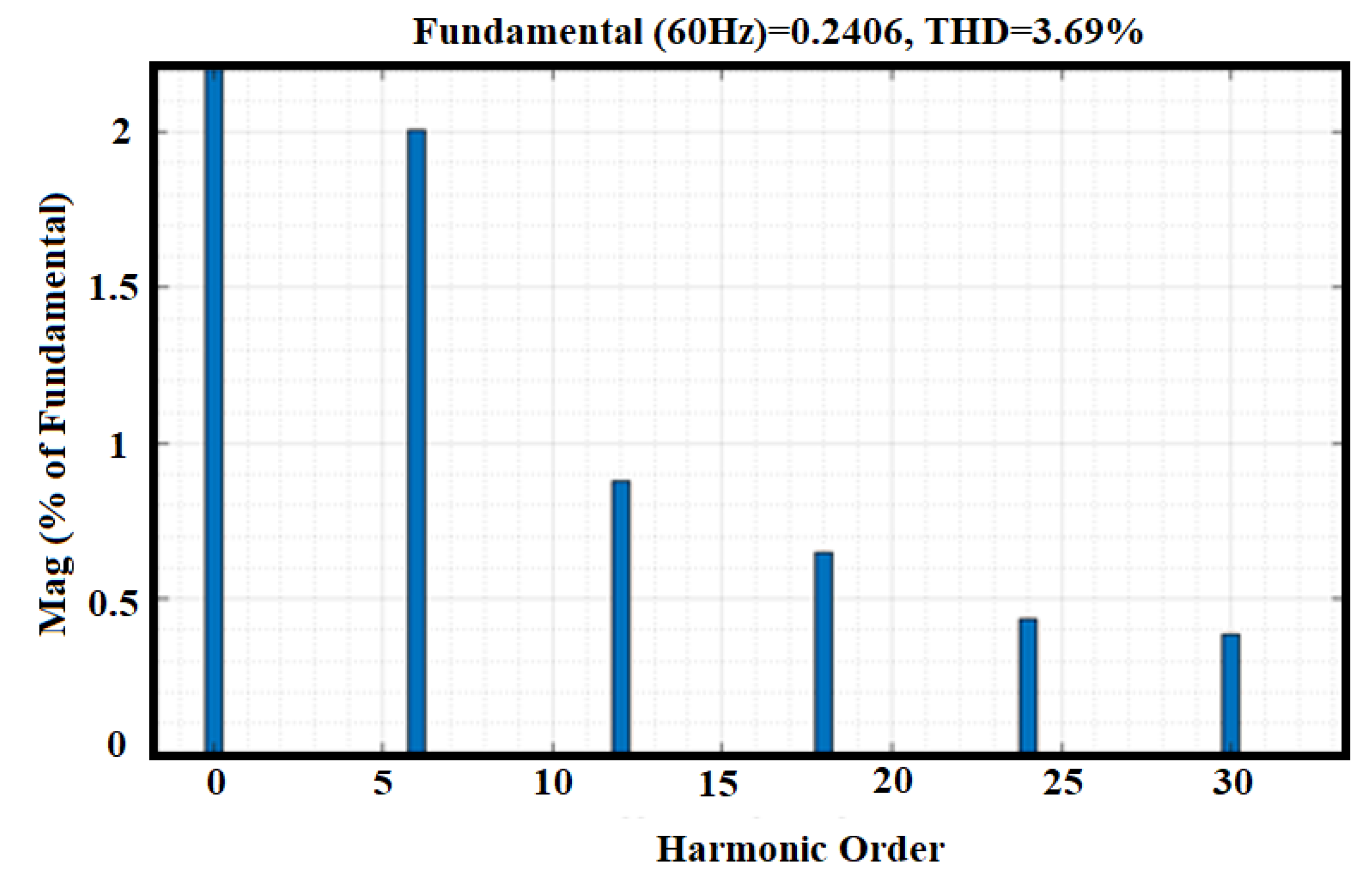
| IMO | 3.69 | 97.73 | 0.098 | 9.4 |
| Measures | SRM [24] | IPSO | IACO | IMO |
|---|---|---|---|---|
| Efficiency (%) | 92.2 | 96.19 | 95.94 | 97.73 |
| THD (%) | 4.95 | 4.75 | 5.36 | 3.69 |
Disclaimer/Publisher’s Note: The statements, opinions and data contained in all publications are solely those of the individual author(s) and contributor(s) and not of MDPI and/or the editor(s). MDPI and/or the editor(s) disclaim responsibility for any injury to people or property resulting from any ideas, methods, instructions or products referred to in the content. |
© 2023 by the authors. Licensee MDPI, Basel, Switzerland. This article is an open access article distributed under the terms and conditions of the Creative Commons Attribution (CC BY) license (https://creativecommons.org/licenses/by/4.0/).
Share and Cite
Narasimhulu, N.; Awasthy, M.; Pérez de Prado, R.; Divakarachari, P.B.; Himabindu, N. Analysis and Impacts of Grid Integrated Photo-Voltaic and Electric Vehicle on Power Quality Issues. Energies 2023, 16, 714. https://doi.org/10.3390/en16020714
Narasimhulu N, Awasthy M, Pérez de Prado R, Divakarachari PB, Himabindu N. Analysis and Impacts of Grid Integrated Photo-Voltaic and Electric Vehicle on Power Quality Issues. Energies. 2023; 16(2):714. https://doi.org/10.3390/en16020714
Chicago/Turabian StyleNarasimhulu, Namala, Mohan Awasthy, Rocío Pérez de Prado, Parameshachari Bidare Divakarachari, and Nadimapalli Himabindu. 2023. "Analysis and Impacts of Grid Integrated Photo-Voltaic and Electric Vehicle on Power Quality Issues" Energies 16, no. 2: 714. https://doi.org/10.3390/en16020714
APA StyleNarasimhulu, N., Awasthy, M., Pérez de Prado, R., Divakarachari, P. B., & Himabindu, N. (2023). Analysis and Impacts of Grid Integrated Photo-Voltaic and Electric Vehicle on Power Quality Issues. Energies, 16(2), 714. https://doi.org/10.3390/en16020714