Abstract
Wireless power transfer (WPT) has been a promising way to transfer power wirelessly over certain distances through the mutual inductance (MI) of the magnetically coupled transmitter and receiver coils, providing significant benefits of convenience, safety, and feasibility to special occasions. The stable output and efficiency cannot be maintained due to the load variation and the inevitable misalignment between the magnetic couplers. High-order compensation topologies that are highly flexible in design due to more compensation elements are essential for the WPT to suppress the load variation and misalignment effects. However, due to core loss and thermal management, high-power-level and high-frequency inductor design have always been challenging for WPT systems. Space occupation and cost are other aspects to be considered for inductor design. Thus integrating these additional bulky inductors into the main coils has been a critical trial. As a result, the compensation topologies’ original input and output profiles will change or even disappear. This paper reviews the existing high-order compensation topologies and their integration principles and implementation for the WPT to obtain high misalignment tolerance. The design objectives and challenges of the integrated compensation topology in terms of misalignment tolerance capability are discussed. The relevant control systems to cope with coil misalignment and load variations are investigated. Challenges and future development of the high-tolerant WPT are discussed.
1. Introduction
Wireless power transfer (WPT) is a promising way of charging and has been utilized in many applications, such as electric vehicles (EVs) [1,2], body-implanted medical devices [3], underwater supplies [4,5], robots [6,7], and drones [8,9]. With the advantages of electrical and mechanical isolation, the flexibility of power supply, and the safety of operation, WPT is a flexible alternative to applications that are not suitable for using wires. A WPT system generally comprises the inverter, compensation network, transmitter and receiver coils, rectifier, filter, and load. The DC voltage source is inverted into the AC input voltage with a specific operation frequency by the inverter on the primary side. A high-frequency magnetic field is generated by the AC flowing in the primary transmitter (Tx) coil, which is magnetically coupled with the secondary receiver (Rx) coil. Moreover, the energy is transferred through the mutual inductance (MI) between the Tx and Rx coils, which will be converted into DC power by the rectifier to charge the batteries. Therefore, MI is a critical design parameter for achieving a highly-performance WPT system [10,11].
In practice, the large air gap makes WPT systems loosely coupled compared to conventional transformers, and the MI is more sensitive to the relative positions between the Tx and Rx coils. The misalignment between coupled coils inevitably results in significant variations in MI, which will deteriorate the output power stability and system efficiency. In addition, load-independent constant current (CC), constant voltage (CV), and/or their hybrid profiles are recommended for charging Li-ion batteries [12,13]. Therefore, the design and implementation of high-performance WPT systems mainly consider variations in both MIs and loads [14,15]. Furthermore, to minimize the volt-ampere (VA) rating of the power supply and reduce the reactive power, the zero-phase angle (ZPA) input is desirable [16,17].
As the critical part of the WPT system, compensation topology is crucial to compensate for the reactive power, improve system efficiency, and determine system output characteristics [18,19]. Series-series (SS), series-parallel (SP), parallel-series (PS), and parallel-parallel (PP), which consist of series or parallel components on the primary and secondary sides, are the four essential topologies. Although the compensation with ZPA input and CC/CV output can be achieved, SS is the only topology independent of MI and the load condition among them [20,21]. The essential topologies have a limited ability to tolerate wide load variations and misalignments. Higher-flexible compensation topologies, which have a higher degree of design freedom due to more resonant components being used, are presented against the MI and load variations. Conversely, more passive components will increase the system’s volume and cost. Furthermore, the core loss and thermal management of high-power-level and high-frequency inductor design will aggravate the core loss and thermal issues. In light of this, numerous integrated topologies are proposed to improve the performance of WPT systems under misalignment conditions [10].
Topology integration in WPT systems means that the additionally compensated inductors generate a magnetic field to couple with the main coils and transfer power. Typically, the topology integration is designed with some special magnetic couplers. For effective integration, the integrated topologies should be designed so that the original ZPA input and load-independent output properties are not affected. Meanwhile, relative control strategies have been proposed to maintain the CC/CV output and improve the overall performance under misalignment conditions.
This paper compares and describes highly flexible compensation topologies, integration methods, and relative control strategies for high misalignment-tolerant WPT systems. Section 2 presents a detailed review of existing misalignment tolerant compensation topologies based on the configuration, effects on the soft-switching and/or ZPA of the inverter, load-independent output properties, and the misalignment tolerance behavior. In Section 3, the topology integration principle and its design objectives can be found. Different integration topologies’ design, implementation, and performance are comprehensively studied, analyzed, and compared. Section 4 discusses the control strategies utilized to cope with load variations and misalignment to increase system efficiency and stability. Section 5 provides the main challenges and future developments, whereas the last section concludes the paper.
2. Highly Flexible Compensation Topologies
Due to the loose coupling between the primary and secondary coils, the reactive power in the WPT system is high [22]. Compensation topologies are essential for the WPT to compensate for the reactive power to offer high power density, efficiency, and flexible output voltage/current. Meanwhile, the variation of MI due to the misalignment between the primary and secondary coils will lead to input impedance change, deterioration of the output power stability, and reduction in the system efficiency [11]. Therefore, the requirements for the misalignment-tolerant output should be considered in the design of the compensation topologies. Some of the common compensation topologies and their design challenges in terms of misalignment tolerance capability are studied.
2.1. High-Order Topologies
To improve the misalignment tolerance, more components, namely inductor (L) and capacitor (C), are added to the basic compensation topologies, forming higher-order compensation topologies. More components may reduce the system efficiency as a tradeoff. However, the additional compensation components offer more freedom for the resonant parameters design to achieve the desired characteristics, such as the load-independent ZPA input, constant output, high power density, and misalignment tolerance. Numerous high-compensation topologies, such as S/SP [23,24], S- [25], S- [26,27], -S [28], -S [29], -S [30,31], -P [32,33], - [34], and - [35,36,37], are proposed along with parameter design methods to overcome the coil misalignment and load variations. Table 1 summarizes these high-order compensation topologies’ typical operating angular frequencies obtaining the ZPA input and constant output conditions.

Table 1.
Typical Characteristics of high-order compensation topologies.
It can be observed from Table 1 that all of these topologies can be designed with ZPA input and load-independent output. A higher degree of design freedom for the WPT system can be obtained by adding more compensation components. In the , , and compensation topologies, the constant amplitude of the output can be adjusted by changing the values of and . However, in the compensation topologies, the restriction of equal inductance values for the compensation inductance and the main coil reduces the flexibility of the topology design. Additionally, the compensation inductor in the -S compensation topology can be designed to be smaller than the -S compensation topology, reducing the system volume and power losses. However, the operating angular frequency of the S/SP and -P compensation topologies are both functions of , increasing the difficulty and complexity of system design. As a result, it is difficult for the system to obtain a stable output under misalignment conditions. Furthermore, for the system with controls, this poses challenges to the system control to be a faster response, higher precision, and wider tracking range to .
Apart from the typical characteristics presented in Table 1, these compensations can also be designed with other output characteristics by changing the operating frequency due to more compensation components. Therefore, the higher-order compensation topologies can implement CC/CV charging profiles, which are more suitable for battery charging [12,13,38]. However, the ZPA input cannot be achieved in both CC and CV charging modes for all these high-order compensation topologies [33]. Therefore, the topology parameters should be redesigned with the actual MI under the misalignment conditions.
In Table 1, it can be found that the output of the S/SP, S-, and S- compensation topologies are all proportional to . When approached zero, i.e., the secondary pad moves out of the misalignment tolerant range, there will be a dramatic increase in the output, causing damage to the load equipment. Meanwhile, the input impedance of the S/SP, S-, and S- compensation topologies are all proportional to , which will cause a significant drop under the large misalignment. As a result, an overcurrent will occur on the primary side. However, the - and -compensation topologies can provide more significant tolerance to coil misalignment. Moreover, comparing the S- and -S, S- and -S topologies, the higher stable system can be achieved by using double - and -compensation topologies.
Numerous novel compensation topologies and optimized design methods are proposed to further improve the misalignment tolerance of the compensation topologies. In [23], a design method for parameters of the S/SP compensation topology is proposed based on the relationship between the primary input impedance angle and secondary input impedance angle with coupling coefficient and load resistance. To make the S/SP compensation topology tune at the optimal coefficient achieving high misalignment tolerance capability, a minimizing output voltage fluctuation design method is provided in [39]. In [40], a novel S- compensation topology is proposed to resist MI changes due to coil misalignment. The ZPA input condition can always be maintained under the load-independent CC and CV output modes, which are shifted based on the filter with a double bandpass. In [41], an S–S– compensation for three-coil WPT with load-independent CV output is proposed against the load variation and coil misalignment. The voltage stress is reduced, and the output power and the system light-load efficiency are improved. In [42], an X-type compensation topology is proposed, which has a stable power transfer capacity without using a dedicated coil design and tight control.
Furthermore, a detuned design method based on the sensitivity of the coupling coefficient is proposed for a family of compensation topologies [43]. However, the design is complicated, and the reactive power due to the non-resonant state increases the system’s losses. The misalignment tolerance capability is insufficient based solely on compensating topology design.
2.2. Reconfigurable Topologies
To overcome the limited misalignment tolerance of the high-order compensation topologies, reconfigurable compensation topologies switching between two or more magnetic couplers or using switchable topologies/components based on coil misalignment conditions are presented, as shown in Figure 1. With the reconfigurable topologies, any random-direction misalignment tolerance can be improved.
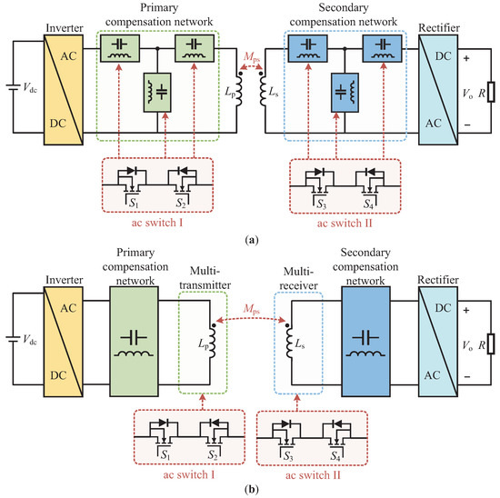
Figure 1.
Schematic of the reconfigurable topologies with (a) switchable topologies/components and (b) switchable multiple couplers.
The reconfigurable topologies switching between different topologies, such as SS and PS (or SP and PP ) topologies [44], - and -S topologies [45], S-S-S and S-S- topologies [46], etc., are proposed. A hybrid compensation topology switched between SS and - topologies is presented in [47] to maintain the system efficiency for a wide range of loads. The two topologies are switched by using two AC switches based on the wireless communication links. In [48], a novel topology switched between SS and -S topologies is proposed to enable CC and CV. In this design, only one relay is utilized. However, these designs mainly focus on achieving inherent CC/CV output profiles under load variations. To achieve both the tolerance to coil misalignment and load variations in a wide range, [49] presents a reconfigurable topology based on two equivalent detuned SS topologies. The two SS topologies switch at the crossover coupling coefficient point by an ac switch to obtain the constant transfer power. To overcome the limitation of SS topology under large misalignment, a switchable topology between the SS and -S is proposed in [50]. By switching at the boundary point, the equivalent MI can be stabilized under the misalignment conditions.
In addition, reconfigurable topologies based on switchable components are proposed to improve the misalignment tolerance. In [51], a shape-independent reconfigurable coil array based on the variable capacitors is proposed to tolerate the misalignment, which can be applied to any conventional coil. By switching the parallel-compensated capacitance of the – topology under misalignment conditions, the constant output power can be maintained over a wide coupling variation [52]. However, for a significant tolerance to coil misalignment and load variation, the switchable compensation components should be designed with a wide resonant matching range in the above methods [53]. Furthermore, multi-coil-based reconfigurable topologies are proposed in [54,55,56]. The stable output is obtained by switching the multi-coils according to the coil misalignment position. A digital transmitter (TX) coil composed of multiple parallel sub-coils is proposed in [57]. The radius of the digital TX coil can be switched to an optimal value for maximum coil-to-coil efficiency, depending on the position of the receiver coil. In [58], a reconfigurable topology linking Two-, Three-, and Four-Coil operation modes is proposed to tolerate air-gap change. By optimizing the turn ratio of the coils, the system can output the desired power with a large air-gap range with ZPA and ZVS-ON conditions. In [59], an intermediate coil, which can be switched by an additional inverter between the repeater-aided and power-interactive modes, is designed to enhance the system efficiency and misalignment tolerance. A novel magnetic coupler with a flexible coil structure according to the relative position of the primary and secondary coils is proposed to enhance the horizontal misalignment tolerance [60]. A stacked coil is designed to tolerate lateral misalignment [61]. The stacked coil is integrated with three layers of coils of different sizes. By switching the coil pair depending on the misalignment, high transfer efficiency can be maintained with an extreme misalignment.
To realize the reconfigurable circuit, numerous selection switches and/or passive components should be added to the primary and/or secondary sides, increasing the system losses, cost, weight, and volume. Furthermore, the switchable passive compensation components used in the above methods are mostly nonlinear adjustments with a limited matching range and difficulty guaranteeing matching accuracy. To ensure precise compensation, the switches must be equipped with a detector and controller, despite applying the linear components [62,63,64]. Moreover, the potential communication delay and interruption issues will result in unreliability for tolerating the coil misalignment and load variations [65,66,67,68,69,70]. The control strategies will be discussed in Section 4.
As analyzed, Table 2 gives a summary of the comparison of the characteristics of different highly flexible compensation topologies.
Table 2.
Comparison of different highly flexible compensation topologies.
3. Topology Integration Principle and Implementation
3.1. Design Objectives for Integration
Although the reconfigurable compensation topologies can mitigate the effects of coil misalignment and load variations on system output, the introduced switches and passive components usually make the system bulky, increasing system volume and losses and causing thermal issues [10,71]. Therefore, compact design and integration for those inductors are necessary [72,73]. The inductors integrated as the compensation coils create more MIs between the primary and secondary pads, as shown in Figure 2. Based on Table 1, the effects of the compensation coils on the input and output profiles of the high-order compensation topologies are shown in Table 3, where is the MI between the primary and secondary main coils, , , , , , , and are the MIs between the compensation coil and primary and secondary main coils.
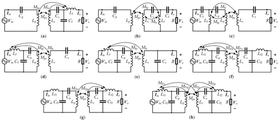
Figure 2.
Conventional high-order network topologies for WPT considering extra couplings brought by the compensation inductors. (a) S- topology. (b) S- topology. (c) -S topology. (d) -S topology. (e) -P topology. (f) Primary-side-integrated - topology. (g) Secondary-side-integrated - topology. (h) Double-side-integrated - topology.
Table 3.
Operational characteristics of high-order compensation topologies with extra couplings using conventional resonant calculation methods.
As shown in Table 3, only the secondary-side-integrated - topology can maintain the CC output. However, it lost the ZPA input condition. For the rest of the topologies, the ZPA input and load-independent constant output cannot be obtained using the original compensation conditions, resulting in high reactive power and reduced power transfer capability. It poses a challenge for achieving high-performance WPT systems. Furthermore, when the misalignment occurs in a large range, especially in the dynamic WPT system, the WPT systems usually experience output power pulsation and efficiency decrease. Therefore, the integration of a compensation topology supporting misalignment tolerance is preferable.
Numerous coil topologies with decoupling designs are proposed to eliminate the effects of the introduced additional MIs due to compensation coils on the original input and output properties of the compensation topologies [74,75,76]. In those designs, compensation coils are decoupled from all coils, which means the magnetic fields they generate have not participated in the power transfer. Moreover, the decoupling design limits the design freedom of compensation coil integration.
To improve the design freedom of high-order compensation topologies integration, the design objectives for topology integration can be summarized as follows:
- (1)
- To reduce the reactive power and system losses, the ZPA input should be obtained.
- (2)
- Decoupling between the compensation coils and the original primary and secondary coils are not required to improve the design freedom.
- (3)
- The load-independent constant output should be obtained to meet the specific charging conditions.
- (4)
- To achieve stable charging, the tolerance for misalignment should be supported.
Many works have been performed on topology integration for high-tolerant WPT systems. These approaches can be classified into two categories: (1) single-sided integration and (2) double-sided integration. A brief literature survey is given on these integration designs.
3.2. Integrated Hybrid Topologies
Hybrid compensation topologies are presented to overcome the limited misalignment tolerance of a single compensation topology. Combining the advantages of two or more topologies, the hybrid compensation topologies provide higher tolerance to the MI and load variations. Based on [77,78,79,80,81,82], the overall schematics of the hybrid compensation topologies are illustrated in Figure 3, including the input-parallel-output-parallel (IPOP), input-series-output-parallel (ISOP), input-parallel-output-series (IPOS), and input-series-output-series (ISOS) topologies. The primary and secondary pads consist of m and n coils, respectively, where , and refer to the conventional integrated topologies, as shown in Figure 2. Moreover, multi-inverter/rectifier WPT systems are proposed based on the hybrid compensation topologies for applications with high output power and flexible output power levels. Based on [31,83,84,85,86], the schematics of the multi-inverter/rectifier WPT system are shown in Figure 4, including the IPOP, ISOP, IPOS, and ISOS structures. In addition, the two types of structures shown in Figure 3 and Figure 4 can be combined [87,88,89,90]. The additional MIs between the primary and secondary coils provide more induced voltage in the secondary coils to tolerate the misalignment. However, more MIs, especially the cross-coupling on the primary and secondary sides, will complicate the compensation topology parameter design. Meanwhile, higher power losses and current stresses will be introduced.
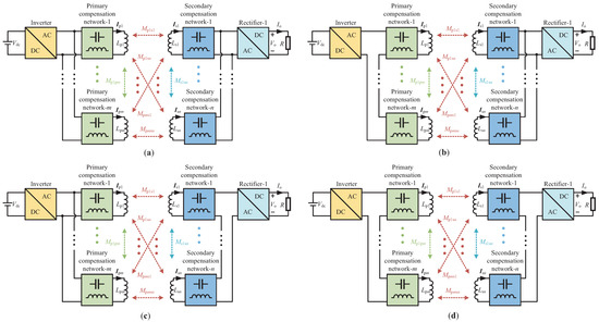
Figure 3.
Schematics of the hybrid compensation topologies. (a) IPOP topology [77]. (b) ISOP topology [78,79]. (c) IPOS topology [80]. (d) ISOS topology [81,82].
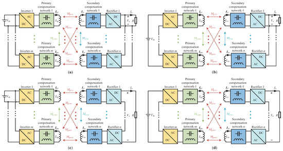
Figure 4.
Diagram of multi-inverter/rectifier WPT modules based on (a) IPOP structure [83,84]. (b) ISOP structure [85,86]. (c) IPOS structure [31]. (d) ISOS structure.
Since coupling coils replace the compensation inductors to participate in the power transfer, the topology integration is designed in conjunction with some special magnetic couplers to address the aforementioned issues. Table 4 provides the basic coil structures utilized in the integration design. Different integration methods are reviewed as follows.
Table 4.
Comparison of magnetic couplers used for compensation topology integration design.
3.2.1. Single-Sided Integration
Based on the special magnetic couplers, a series of integration methods are proposed based on the reversely connected coil structures [91,92], as shown in Figure 5a. Multiple anti-parallel square coils are integrated into the main coil to maintain the load power under horizontal misalignment [100,101]. By integrating the reversely connected inner coil into the main coil, the decline in the mutual inductances between the transmitter and receiver coils, the receiver and reversely connected coils can be the same within a certain range of misalignment. As a result, the constant MI difference is achieved to stabilize the system output. In [102], an optimization design based on a cost function is proposed to increase the degree of freedom for the reversely connected coil structure, as shown in Figure 5b. By optimizing the parallel-compensated capacitance in the network, the restriction on the variation correlation of the MIs between the primary and secondary pads is eliminated. However, the design of constant MI difference will decrease the equivalent MI between the primary and secondary pads, resulting in reduced power transfer capability. In [103], identical compensation and transmitter coils configured in a reversed-series structure are firmly connected to increase the magnetic flux density.
Contrary to the reversely connected coil structures, a structure with complementary-coupling effects of both compensation and main coils is another effective solution to mitigate the misalignment effects. A transmitter integrated by two asymmetrically decoupled unipolar coils is proposed based on the dual-coupled -S compensation topology [104]. The high misalignment tolerance is achieved with the opposite impacts of MIs between the two decoupled coils and the receiver coil on output power. In [105], a primary integrated - compensation topology based on a dual-channel DDP-type transmitter coil is proposed. The DDP coil is combined with a DD coil and a flux pipe (or solenoid coil) (P coil). A hybrid magnetic coupler integrated by DD and solenoid coils, as shown in Figure 5c, is proposed to enhance the misalignment tolerance [106,107]. Similarly, a new hybrid XPAD derived from solenoids is proposed in [108]. The dual-channel DDP and XPAD coils both consist of a series-connected DD and a solenoid coil, where the solenoid coil is arranged in the gaps between the turns of the DD coil. The system has a higher tolerance to vertical and lateral misalignments by providing horizontal and vertical coupling effects.
For the secondary side, a secondary-sided integration design for the input-parallel output-series structure with -S compensation is proposed in [109]. The primary and secondary coils are orthogonal decoupled transformers consisting of the DD and solenoid coils, as shown in Figure 5d. In [110], a high-misalignment tolerate S-S/ hybrid WPT with two receivers is proposed. The primary coils are composed of two overlapped DD coils connected reversely in series, as shown in Figure 5e. The two receiver coils are rectangular, have the same size, and are designed to be BP coils. To reduce the receiver volume, a compact DD two-quadrature (DD2Q) receiver is designed as an S/P-P converter to reduce output fluctuation under lateral and longitudinal misalignments [87]. In this design, two rectangular coils are designed to be BP-type coils and integrated into the symmetrical positions of the DD coil, as shown in Figure 5f. Table 5 summarizes the main features of different single-sided integration designs.
Table 5.
Summary of the single-sided integration designs.
3.2.2. Double-Sided Integration
Double-sided integration designs are proposed to make the system more compact and improve misalignment tolerance. Generally, the double-sided integration designs are used for hybrid compensation topologies due to the multi-transmitter/receiver structure. For multiple WPT systems, a general design method for a family of hybrid compensation topologies is proposed in [111,112,113] to maintain the system output under misalignment conditions. In [80], a hybrid topology formed by an -S topology and an S- topology is proposed based on overlapped rectangular and DD coils. The two topologies are connected in parallel at the primary side and series at the secondary side. However, the current in S compensation topology increases exponentially and even destroys the system when there is a high misalignment. To avoid the overcurrent in the S compensation topology, a hybrid WPT topology in which the primary and S topologies are connected in series based on the Quadruple-D Quadrature Pads (QDQPs) is proposed [78], as shown in Figure 5g.

Figure 5.
Integrated magnetic coupler topologies. (a) Reversely series coils [91,92]. (b) New reversely series coils [102]. (c) SDDP coils [106,107]. (d) Orthogonal decoupled transformer [109]. (e) Overlapped DD coils [110]. (f) DD two-quadrature (DD2Q) coils [87]. (g) Quadruple-D Quadrature Pads (QDQPs) [78]. (h) Overlapped rectangular and DD coils [114]. (i) Orthogonal overlapped DD coils [79]. (j) Cross-shaped hybrid DD coils [81]. (k) Overlapped rectangular and multi-DD coils [83]. (l) Decoupled Multi-Unipolar Coils [90].

Since the non-polarized and polarized coils are inherently decoupled under overlapped conditions, the overlapped rectangular and DD coils, and the orthogonal overlapped DD coils are designed to eliminate the effects of the cross-couplings [79,114], as shown in Figure 5h,i. As shown in Figure 5h, it can be regarded as a DDQ coil [80]. It should be noted that the position and size of the rectangular and DD coils can be changed [115]. In [79], an orthogonal DD coils-based hybrid compensation is proposed for an input-series-output-parallel (ISOP) WPT with a single-ended resonant converter. An integration method for a double-sided S- hybrid compensation topology based on a cross-shaped hybrid DD coil is proposed in [81], as shown in Figure 5j. In [98], DD coils are integrated into the rectangular main coils to enhance the front-to-rear and vertical misalignments of --compensated WPT. The DD coils are small enough to eliminate the extra couplings even under the misalignment conditions. In [83], an integrated - compensation topology in a multi-transmitter/receiver structure is proposed. The DD and rectangular coils are adopted as the main coils of the two inverters to eliminate the cross-coupling effects. All the compensation coils are DD-type coils placed orthogonally to the DD main coils, as shown in Figure 5k. The coupling between the main coils is not affected by the compensation coils under the misalignment condition. Based on DD and rectangular coils, an integrated topology with parallel S- and -type compensations in the primary is proposed in [116]. In the network, inductances are composed of two orthogonally overlapped DD coils. Without considering the decoupling between the compensation coils and the original primary and secondary coils, a hybrid compensation topology with a dual-concentric-coil transmitter and single-coil receiver is proposed in [117].
However, in the design of double-sided integration, some issues still need attention. In [84], an --compensated input-parallel-output-series (IPOS) multiple WPT system is presented. Although both the two transmitters and the two receivers use the non-polarized and polarized coils, the effect of cross-couplings can be avoided only under one misalignment direction. As the misalignment increases, the cross-couplings will present again, and the stable power transfer capacity and ZPA input will be lost. A novel integrated double-sided compensation is introduced in [88]. The naturally decoupled DD and rectangular coils are used as the transmitter, and the BP coil is used as the receiver. However, the BP coil is difficult to design to achieve the decoupled overlapping value. An integrated TP coil using double-sided -compensated WPT is proposed to achieve horizontal, vertical, and rotational misalignments [89]. Orthogonal DD coils are integrated as the transmitter, but the decoupling design for the TP coil increases the system’s complexity. In [90], an integrated -S-compensated multiple-transmitter-multiple-receiver system is proposed. In this design, two unipolar decoupling coils ( and ) are integrated into two unipolar main coils ( and ) to mitigate the MIs of the same-side coils. As shown in Figure 5l, and and and are connected in series to form two transmitting coils, respectively. The decoupling between the same-side coils is obtained by designing and . Meanwhile, the low-power areas of the two unipolar coils are mitigated. However, the compensation inductances in these designs are not integrated, and bulky volume and high power losses are still unsolved.
Furthermore, since the DD coils have a good misalignment tolerance in only one direction, multi-DD coils [81], compact quadruple-D quadrature pad (QDQP) coils [78], and compact double-D quadrature pad (DDQP) coils [82], combined with a hybrid compensation topology design, are proposed to improve the misalignment tolerance capability on the horizontal plane. The equivalent MI is stabilized with the opposite gain trends of the two hybrid compensation topologies under misalignment conditions [82]. Table 6 provides some key features of the double-sided integration designs.
Table 6.
Summary of the double-sided integration designs.
4. Control Systems
This section provides an overview of the WPT control systems to tolerate coil misalignment and load variations to achieve a stable output. The aims of the system controls can be described as the following three:
- (1)
- Ensuring the required power is transferred to the load even under misalignment conditions.
- (2)
- Maintaining the load-independent constant output to meet the specific charging needs.
- (3)
- Achieving maximum system efficiency with the ZPA input condition.
A number of control schemes have been proposed to achieve the load-independent CC and/or CV output and misalignment tolerance, such as additional DC-DC converter [118,119,120], frequency tuning [52,121], maximum frequency tracking [122], phase shift control [123,124,125], duty-cycle control [126,127], load identification [128], and hybrid control strategy [129,130]. These strategies can be classified as single-sided control and double-sided control. The overviewed schematic of control systems is illustrated in Figure 6.
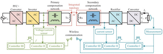
Figure 6.
Schematic of possible control strategies for WPT systems.
4.1. Single-Sided Control
4.1.1. Primary-Sided Control
The inverter is commonly controlled in the primary-sided control strategies based on the information on the battery voltage/current, which is measured by a load identification system and delivered to the primary side by a wireless communication module. By analyzing that information, the firing angle of the thyristors and duty-cycle and switching frequency of the inverter are controlled by the frequency tuning, phase shift, and duty-cycle controllers to obtain the desired input voltage.
In [131], a multi-band frequency tracking control is proposed for S--compensated WPT to match CC and CV modes and to mitigate the misalignment effects. For misalignment cases, two narrow frequency bands are selected for control to maintain the CC output and limit reactive power. The duty ratio of the inverter is controlled to maintain the CV output. A hybrid control strategy based on the phase shift control and the switch-controlled capacitor is presented for an -S-compensated WPT system in [129]. In the whole voltage regulation range, the reactive current in the resonant tank is minimized due to the switch-controlled capacitor while achieving ZVS. Moreover, the phase shift control reduces the power losses of the primary coil at a light load. The variable frequency control method can also be used to regulate the CC and CV outputs with the ZPA condition [132]. However, the frequency splitting phenomenon could lead to system instability [80,133].
Furthermore, the information of the battery voltage/current can be used to control the reconfiguration of the compensation topology. As a result, the output can be regulated to stable under the misalignment and load variation conditions. Based on the pulse width modulation (PWM)-controlled inductor and capacitor, a control method to improve power output under weak coupling is proposed in [134]. The ZPA input and full output power can be maintained under the misalignment condition by regulating the inductor and capacitor. Meanwhile, an auxiliary MI identification method based on the primary side parameters is utilized to achieve parameter regulation.
Moreover, the DC input voltage for the primary inverter can be adjusted by controlling the primary DC-DC converter to track the constant output based on the information of the battery voltage/current [135]. For the -N compensation topology, a primary-side linear control based on an improved load parameters identification method is proposed in [119]. By changing the duty of the buck converter, the CC/CV output under a wide load variation is achieved. On the other hand, the inverter can be controlled based on the primary voltage/current information without any communication between the primary and secondary sides, which has cost benefits [136].
4.1.2. Secondary-Sided Control
In secondary-sided control, the system output can be stabilized in three ways: (i) the controlled active rectification, (ii) the additional DC/DC converter, and (iii) the compensation topology. None of these methods need to communicate with the primary side; however, the information of the battery voltage/current still needs to be measured. Moreover, the secondary active rectifier can be controlled by only the current information of the receiver without sampling the load condition.
For the -S-compensated WPT system, a novel pulse density modulation (PDM) control based on load-independent CC/CV output for the SAR is proposed in [137]. The CC/CV output can be regulated in a wide load range without wireless communication. A novel operation approach combining the merits of load-independent transfer characteristics and load impedance matching is provided in [138]. By controlling the switch-controlled capacitor and the SAR on the secondary side, the constant power (CP) output and load matching for maximum efficiency is obtained.
Furthermore, detecting misalignments is another way to tolerate and correct misalignments [139]. In this method, positioning control based on misalignment-sensing coils is proposed to reduce the misalignments. In [140], a receiver position identification method based on integrated -S compensation topology is proposed. The compensation inductance, constituted by four symmetrical Q coils connected in series, is integrated into the main coil. By sampling the voltage and current of the compensation and transmitter coils, the accurate identification of the receiver’s position is achieved, thereby suppressing the misalignment. The back-end DC/DC converter-based approach is proposed in [118]. However, extra weight/volume, cost, and power losses will be unavoidable for the additional DC/DC converter.
Both in the primary- and secondary-sided controls, self-tuning methods based on switched components with simplified control parameters are proposed to improve the misalignment tolerance. Those control methods are generally used in reconfigurable and hybrid compensation topologies. In [141], a self-tuning method based on switch-controlled capacitors for a series-series (S-S)-compensated WPT system is proposed. In this method, the resonant parameters are not required. Similarly, a controlled capacitor matrix and a continuously controlled variable inductor are designed in [142,143,144], respectively. However, for a large tolerance to misalignment and load variation, the controlled composition components should be designed with a wide resonant matching range in the above methods [145]. Regardless of the extra costs, reliability issues could be introduced due to the speed and accuracy of the control.
4.2. Double-Sided Control
In double-sided control, the primary and secondary sides should be controlled simultaneously, in which fast and reliable communication between the primary and secondary sides is generally required.
To reduce the converter losses and avoid the hard switching and harmonics in duty-cycle controls for a large load range, a multivariable control strategy based on the optimal combination of all control variables is proposed to achieve constant output under large coil misalignment and load variations and improve the system efficiency [126]. Based on a software phase-locked-loop (SPLL), the phase error between the secondary side current and the reference of the pulse width modulation (PWM) modules is filtered to synchronize the primary and secondary-side driving signals. In [146], a double-side self-tuning method is proposed to tolerate the mutual inductance variation based on the -S topology. However, the parameter recognition method is required to recognize both the self- and mutual inductances. The potential risks, such as latency and data losses of wireless communication, will cause a breakdown or even destruction of the WPT system. A self-tuning method based on two switch-controlled capacitors on each primary and secondary side is proposed [147]. Without wireless communication or parameter identification, the design can maintain a high power factor and the desired output power against self- and mutual inductance variation. In [148], a control strategy with ZPA and optimal load conditions is proposed to cope with large coil misalignment without reliable wireless communication. In this control, the primary inverter and the secondary converter can be operated independently with control freedom. Nevertheless, the stability issues should be considered carefully using two independent controllers [149].
As analyzed, in the integration design of WPT systems, control is implemented to improve the power transfer efficiency and misalignment tolerance, and to regulate the CC/CV charging profiles of the battery. Table 7 summarizes the advantages and disadvantages of different control strategies.
Table 7.
Summary and comparison of the control strategies.
5. Challenges and Future Developments
Based on the extensive review in this paper, the stability, reliability, and efficiency of WPT systems suffer significantly due to coil misalignment and load variations. Integrated high-order compensation topologies and control methods have been proposed to address the issues. Although the topology integration can reduce the system volume and increase the design freedom, the following challenges need to be overcome in future studies:
- (1)
- Innovate new integrated topologies to improve the coupler performance. The topology integration is encouraged to be unaffected by parameter changes and enhance the output to tolerate lateral, vertical, and rotational misalignments. The design complexity and lightweight coupler should be considered. Furthermore, the ZPA input condition should be maintained to reduce power losses during the integration design. In addition, the heat and thermal issues in the topology integration design also need to be concerned.
- (2)
- The development of an integration method for the dynamic wireless power transfer (DWPT) to adapt to the development of autonomous driving. Due to more severe misalignment, the integration design, especially the primary side, should enable extensive horizontal misalignment tolerant range while maintaining high system efficiency. Moreover, the fast and reliable control and position detecting systems, if necessary, can be utilized.
- (3)
- The integration design should guarantee interoperability between different charging systems. Therefore, a more general integration design featuring compensation network and coil interoperability should be studied, which can maintain the misalignment tolerance capacity between different systems and meet the performance requirements.
- (4)
- Space electromagnetic safety is quite a challenge. Electromagnetic interference (EMI) caused by leakage in the magnetic field can lead to the poor performance of electronics and even malfunction or stop working altogether. Furthermore, excessive magnetic field radiation could bring about adverse health effects or even harm human body tissue. In addition, leakage in the magnetic field can be coupled with the implanted device. Therefore, more effective shielding technology should be studied. A more compact topology integration design can also be the solution to achieve this goal.
- (5)
- The design of a fast, stable, and reliable control system. A control strategy that achieves the desired performances with the fewest design parameters and control variables can reduce design complexity and system cost. Moreover, the accuracy, security, and less latency communication between the primary and secondary sides are essential to tolerate coil misalignment and load variations.
- (6)
- Optimize metal object detection methods in high-power WPT systems. The metal objects between the primary and secondary coils will decrease the power transfer efficiency and cause safety issues, such as heating and accidental fire. For the integrated topologies, the complex coupling conditions will increase the design difficulty of the detection system based on detection coils. Therefore, integrating the detection coils into the integrated topology without affecting the performance of the integrated topology is a challenge for the design of the detection system. Moreover, the detection methods should be designed with high sensitivity and reliability, no blind zone, and be cost-effective.
6. Conclusions
This paper reviews some recent advances in the high-order compensation topology and the integration design for WPT systems to address the misalignment issues. Various high-flexible compensation topologies and control strategies are summarized to improve the tolerance to coil misalignment and load variations. The effects of the additional coupling due to the compensation inductance on the system performance are analyzed. Due to the extra couplings, the ZPA input and load-independent constant output will be lost using conventional resonant calculation methods. This paper provides the integration principles of the compensation topology. The existing integration methods combine the compensation topology and specific magnetic coupler to improve the tolerance to coil misalignment and load variations are summarized and compared. The design objectives, challenges, and suggestions for future development are presented.
Author Contributions
Writing—original draft preparation, Z.Y.; supervision, Q.Y.; writing—review and editing, Z.Y., X.Z. and P.Z.; figures and tables, X.M., Z.C. and M.X. All authors have read and agreed to the published version of the manuscript.
Funding
This research was funded by This research was funded by the National Natural Science Foundation of China Grant number 52122701, 52207010, and 52077153.
Institutional Review Board Statement
Not applicable.
Informed Consent Statement
Not applicable.
Data Availability Statement
Not applicable.
Conflicts of Interest
The authors declare no conflict of interest. The funders had no role in the design of the study; in the collection, analyses, or interpretation of data; in the writing of the manuscript; or in the decision to publish the results.
References
- Cirimele, V.; Diana, M.; Freschi, F.; Mitolo, M. Inductive Power Transfer for Automotive Applications: State-of-the-Art and Future Trends. IEEE Trans. Ind. Appl. 2018, 54, 4069–4079. [Google Scholar] [CrossRef]
- Mou, X.L.; Gladwin, W.T.; Zhao, R.; Sun, H.J. Survey on magnetic resonant coupling wireless power transfer technology for electric vehicle charging. IET Power Electron. 2019, 12, 3005–3020. [Google Scholar] [CrossRef]
- Roy, S.; Azad, A.N.M.W.; Baidya, S.; Alam, M.K.; Khan, F. Powering Solutions for Biomedical Sensors and Implants Inside the Human Body: A Comprehensive Review on Energy Harvesting Units, Energy Storage, and Wireless Power Transfer Techniques. IEEE Trans. Power Electron. 2022, 37, 12237–12263. [Google Scholar] [CrossRef]
- Yan, Z.; Song, B.; Zhang, Y.; Zhang, K.; Mao, Z.; Hu, Y. A Rotation-Free Wireless Power Transfer System with Stable Output Power and Efficiency for Autonomous Underwater Vehicles. IEEE Trans. Power Electron. 2019, 34, 4005–4008. [Google Scholar] [CrossRef]
- Zeng, Y.; Rong, C.; Lu, C.; Tao, X.; Liu, X.; Liu, R.; Liu, M. Misalignment Insensitive Wireless Power Transfer System Using a Hybrid Transmitter for Autonomous Underwater Vehicles. IEEE Trans. Ind. Appl. 2022, 58, 1298–1306. [Google Scholar] [CrossRef]
- Al Mahmud, S.A.; Panhwar, I.; Jayathurathnage, P. Large-Area Free-Positioning Wireless Power Transfer to Movable Receivers. IEEE Trans. Ind. Electron. 2022, 69, 12807–12816. [Google Scholar] [CrossRef]
- Zhao, H.; Zhang, Y.; Hu, J.; Chen, Z.; Zhou, J.; Sun, M.; Yang, D. Convex Optimization of Mutual Inductance Between Multiantiparallel Coils for Distance-Insensitive Wireless Charging of Air–Ground Robots. IEEE Internet Things J. 2022, 9, 10705–10717. [Google Scholar] [CrossRef]
- Zhang, Z.; Shen, S.; Liang, Z.; Eder, S.H.K.; Kennel, R. Dynamic-Balancing Robust Current Control for Wireless Drone-in-Flight Charging. IEEE Trans. Power Electron. 2021, 37, 3626–3635. [Google Scholar]
- Wang, J.; Chen, R.; Cai, C.; Zhang, J.; Wang, C. An Onboard Magnetic Integration Based WPT System for UAV Misalignment-Tolerant Charging with Constant Current Output. IEEE Trans. Transp. Electrif. 2022. accepted. [Google Scholar] [CrossRef]
- Vu, V.B.; Ramezani, A.; Triviño, A.; González-González, J.M.; Kadandani, N.B.; Dahidah, M.; Pickert, V.; Narimani, M.; Aguado, J. Operation of Inductive Charging Systems under Misalignment Conditions: A Review for Electric Vehicles. IEEE Trans. Transp. Electrif. 2022. accepted. [Google Scholar] [CrossRef]
- Barakat, A.; Yoshitomi, K.; Pokharel, R.K. Design Approach for Efficient Wireless Power Transfer Systems During Lateral Misalignment. IEEE Trans. Microw. Theory Tech. 2018, 66, 4170–4177. [Google Scholar] [CrossRef]
- Qu, X.; Chu, H.; Wong, S.; Tse, C.K. An IPT Battery Charger with Near Unity Power Factor and Load-Independent Constant Output Combating Design Constraints of Input Voltage and Transformer Parameters. IEEE Trans. Power Electron. 2019, 34, 7719–7727. [Google Scholar] [CrossRef]
- Tran, D.H.; Vu, V.B.; Choi, W. Design of a High-Efficiency Wireless Power Transfer System with Intermediate Coils for the On-Board Chargers of Electric Vehicles. IEEE Trans. Power Electron. 2018, 33, 175–187. [Google Scholar] [CrossRef]
- Lee, Y.D.; Kim, K.W.; Moon, G.W. A Self-Compensated Planar Coil with Integrated Single-Switch Regulator for Wireless Power Transfer (WPT) Systems. IEEE Trans. Power Electron. 2021, 36, 10954–10958. [Google Scholar] [CrossRef]
- Yang, L.; Ren, L.; Shi, Y.; Wang, M.; Geng, Z. Analysis and Design of a S/S/P-Compensated Three-coil Structure WPT System with Constant Current and Constant Voltage Output. IEEE Trans. Emerg. Sel. Top. Power Electron. 2022. accepted. [Google Scholar] [CrossRef]
- Yang, B.; Lu, Y.; Peng, Y.; He, S.; Chen, Y.; He, Z.; Mai, R.; Wang, Z. Analysis and Design of a T/S Compensated IPT System for AGV Maintaining Stable Output Current Versus Air Gap and Load Variations. IEEE Trans. Power Electron. 2022, 37, 6217–6228. [Google Scholar] [CrossRef]
- Nguyen, H.T.; Alsawalhi, J.Y.; Hosani, K.A.; Al-Sumaiti, A.S.; Jaafari, K.A.A.; Byon, Y.J.; Moursi, M.S.E. Review Map of Comparative Designs for Wireless High-Power Transfer Systems in EV Applications: Maximum Efficiency, ZPA, and CC/CV Modes at Fixed Resonance Frequency Independent From Coupling Coefficient. IEEE Trans. Power Electron. 2022, 37, 4857–4876. [Google Scholar] [CrossRef]
- Shevchenko, V.; Husev, O.; Strzelecki, R.; Pakhaliuk, B.; Poliakov, N.; Strzelecka, N. Compensation Topologies in IPT Systems: Standards, Requirements, Classification, Analysis, Comparison and Application. IEEE Access 2019, 7, 120559–120580. [Google Scholar] [CrossRef]
- Zhang, W.; Mi, C.C. Compensation Topologies of High-Power Wireless Power Transfer Systems. IEEE Trans. Veh. Technol. 2016, 65, 4768–4778. [Google Scholar] [CrossRef]
- Alam, B.; Ahmad, A.; Rafat, Y.; Alam, M.S. A Review on Power Pad, Topologies and Standards of Wireless Charging of Electric Vehicles. In Proceedings of the International Conference on Decision Aid Sciences and Applications, Chiangrai, Thailand, 23–25 March 2022; pp. 827–835. [Google Scholar]
- Venkatesan, M.; Rajamanickam, N.; Vishnuram, P.; Bajaj, M.; Blazek, V.; Prokop, L.; Misak, S. A Review of Compensation Topologies and Control Techniques of Bidirectional Wireless Power Transfer Systems for Electric Vehicle Applications. Eneries 2022, 15, 7816. [Google Scholar] [CrossRef]
- Li, S.; Mi, C.C. Wireless Power Transfer for Electric Vehicle Applications. IEEE Trans. Emerg. Sel. Top. Power Electron. 2015, 3, 4–17. [Google Scholar]
- Wang, Y.; Mai, J.; Yao, Y.; Xu, D. Analysis and Design of an IPT System Based on S/SP Compensation with Improved Output Voltage Regulation. IEEE Trans. Industr. Inform. 2020, 16, 3256–3266. [Google Scholar] [CrossRef]
- Huang, Z.; Fang, Z.; Lam, C.-S.; Mak, P.-I.; Martins, R.P. Cost-Effective Compensation Design for Output Customization and Efficiency Optimization in Series/Series-Parallel Inductive Power Transfer Converter. IEEE Trans. Ind. Electron. 2020, 67, 10356–10365. [Google Scholar] [CrossRef]
- Mai, R.; Chen, Y.; Zhang, Y.; Yang, N.; Cao, G.; He, Z. Optimization of the Passive Components for an S-LCC Topology-Based WPT System for Charging Massive Electric Bicycles. IEEE Trans. Ind. Electron. 2018, 65, 5497–5508. [Google Scholar] [CrossRef]
- Yao, Y.; Wang, Y.; Liu, X.; Pei, Y.; Xu, D.; Liu, X. Particle Swarm Optimization-Based Parameter Design Method for S/CLC-Compensated IPT Systems Featuring High Tolerance to Misalignment and Load Variation. IEEE Trans. Power Electron. 2015, 34, 5268–5282. [Google Scholar] [CrossRef]
- Wang, Y.; Yao, Y.; Liu, X.; Xu, D. S/CLC Compensation Topology Analysis and Circular Coil Design for Wireless Power Transfer. IEEE Trans. Transp. Electrif. 2017, 3, 496–507. [Google Scholar] [CrossRef]
- Wang, Y.; Liu, W.; Huangfu, Y. A Primary-Sided CLC Compensated Wireless Power Transfer System Based on the Class D Amplifier. In Proceedings of the IECON 2018—44th Annual Conference of the IEEE Industrial Electronics Society, Washington, DC, USA, 21–23 October 2018; pp. 943–947. [Google Scholar]
- Gao, W.; Jiang, L.; Chen, Q.; Ren, X.; Zhang, Z.; Wong, S. Analysis and Design of an Integrated LCL-S Contactless Resonant Converter. In Proceedings of the IEEE Conference on Applied Power Electronics Conference and Exposition, San Antonio, TX, USA, 4–8 March 2018; pp. 3178–3182. [Google Scholar]
- Kan, T.; Lu, F.; Nguyen, T.; Mercier, P.P.; Mi, C.C. An Operation Mode Selection Method of Dual-Side Bridge Converters for Efficiency Optimization in Inductive Power Transfer. IEEE Trans. Power Electron. 2020, 35, 9992–9997. [Google Scholar]
- Li, Y.; Hu, J.; Li, X.; Mai, R.; Li, Z.; Liu, M.; He, Z. Efficiency Analysis and Optimization Control for Input-Parallel Output-Series Wireless Power Transfer Systems. IIEEE Trans. Power Electron. 2020, 35, 1074–1085. [Google Scholar] [CrossRef]
- Lu, J.; Zhu, G.; Wang, H.; Lu, F.; Jiang, J.; Mi, C.C. Sensitivity Analysis of Inductive Power Transfer Systems with Voltage-Fed Compensation Topologies. IEEE Trans. Veh. Technol. 2019, 68, 4502–4513. [Google Scholar] [CrossRef]
- Vu, V.; Phan, V.; Dahidah, M.; Pickert, V. Multiple Output Inductive Charger for Electric Vehicles. IIEEE Trans. Power Electron. 2019, 34, 7350–7368. [Google Scholar] [CrossRef]
- Yao, Y.; Wang, Y.; Liu, X.; Lin, F.; Xu, D. A Novel Parameter Tuning Method for a Double-Sided LCL Compensated WPT System with Better Comprehensive Performance. IIEEE Trans. Power Electron. 2018, 33, 8525–8536. [Google Scholar] [CrossRef]
- Song, K.; Wei, R.; Yang, G.; Zhang, H.; Li, Z.; Huang, X.; Jiang, J.; Zhu, C.; Du, Z. Constant Current Charging and Maximum System Efficiency Tracking for Wireless Charging Systems Employing Dual-Side Control. IEEE Trans. Ind. Appl. 2020, 56, 622–634. [Google Scholar] [CrossRef]
- Wang, F.; Zhang, W.; Ye, L.; Guo, J.; Liu, K.; Do, H.T. A Design Method to Implement ZVS for Electric Vehicle Wireless Charging System with Double-Side LCC Compensation. IEEE Trans. Emerg. Sel. Top. Power Electron. 2021, 9, 3791–3801. [Google Scholar] [CrossRef]
- Vu, V.B.; Tran, D.H.; Choi, W. Implementation of the Constant Current and Constant Voltage Charge of Inductive Power Transfer Systems with the Double-Sided LCC Compensation Topology for Electric Vehicle Battery Charge Applications. IEEE Trans. Power Electron. 2018, 33, 7398–7410. [Google Scholar] [CrossRef]
- Chen, Y.; Kou, Z.; Zhang, Y.; He, Z.; Mai, R.; Cao, G. Hybrid Topology with Configurable Charge Current and Charge Voltage Output-Based WPT Charger for Massive Electric Bicycles. IEEE Trans. Emerg. Sel. Top. Power 2018, 33, 1581–1594. [Google Scholar] [CrossRef]
- Yao, Y.; Wang, Y.; Liu, X.; Lu, K.; Xu, D. Analysis and Design of an S/SP Compensated IPT System to Minimize Output Voltage Fluctuation Versus Coupling Coefficient and Load Variation. IEEE Trans. Veh. Technol. 2018, 67, 9262–9272. [Google Scholar] [CrossRef]
- Zhang, Y.; Wei, G.; Wang, C.; Yin, Y.; Feng, J.; Na, T.; Song, K.; Zhu, C. A Hybrid Compensation Topology with Constant Current and Constant Voltage Outputs for Wireless Charging System. IEEE Trans. Transp. Electrif. 2022. accepted. [Google Scholar] [CrossRef]
- Darvish, P.; Mekhilef, S.; Illias, H.A.B. A Novel S–S–LCLCC Compensation for Three-Coil WPT to Improve Misalignment and Energy Efficiency Stiffness of Wireless Charging System. IEEE Trans. Power Electron. 2021, 36, 1341–1355. [Google Scholar] [CrossRef]
- Feng, H.; Dayerizadeh, A.; Lukic, S.M. A Coupling-Insensitive X-Type IPT System for High Position Tolerance. IEEE Trans. Ind. Electron. 2021, 68, 6917–6926. [Google Scholar] [CrossRef]
- Mai, J.; Wang, Y.; Yao, Y.; Xu, D. Analysis and Design of High-Misalignment-Tolerant Compensation Topologies with Constant-Current or Constant-Voltage Output for IPT Systems. IEEE Trans. Power Electron. 2021, 36, 2685–2695. [Google Scholar] [CrossRef]
- Qu, X.; Han, H.; Wong, S.; Tse, C.K.; Chen, W. Hybrid IPT Topologies with Constant Current or Constant Voltage Output for Battery Charging Applications. IEEE Trans. Power Electron. 2015, 30, 6329–6337. [Google Scholar] [CrossRef]
- Wang, D.; Qu, X.; Yao, Y.; Yang, P. Hybrid Inductive-Power-Transfer Battery Chargers for Electric Vehicle Onboard Charging with Configurable Charging Profile. IEEE trans. Intell. Transp. Syst. 2021, 22, 592–599. [Google Scholar] [CrossRef]
- Li, Y.; Xu, Q.; Lin, T.; Hu, J.; He, Z.; Mai, R. Analysis and Design of Load-Independent Output Current or Output Voltage of a Three-Coil Wireless Power Transfer System. IEEE Trans. Transp. Electrif. 2018, 4, 364–375. [Google Scholar] [CrossRef]
- Rezazade, S.; Shahirinia, A.; Naghash, R.; Rasekh, N.; Afjei, E. A Novel Efficient Hybrid Compensation Topology for Wireless Power Transfer. IEEE Trans. Ind. Electron. 2022. accepted. [Google Scholar] [CrossRef]
- Mao, X.; Chen, J.; Zhang, Y.; Dong, J. A Simple and Reconfigurable Wireless Power Transfer System with Constant Voltage and Constant Current Charging. IEEE Trans. Power Electron. 2022, 37, 4921–4925. [Google Scholar] [CrossRef]
- Chen, Y.; Yang, B.; Li, Q.; Feng, H.; Zhou, X.; He, Z.; Mai, R. Reconfigurable Topology for IPT System Maintaining Stable Transmission Power Over Large Coupling Variation. IEEE Trans. Power Electron. 2020, 35, 4915–4924. [Google Scholar] [CrossRef]
- Zhang, Y.; Pan, W.; Wang, H.; Shen, Z.; Wu, Y.; Dong, J.; Mao, X. Misalignment-Tolerant Dual-Transmitter Electric Vehicle Wireless Charging System with Reconfigurable Topologies. IEEE Trans. Power Electron. 2022, 37, 8816–8819. [Google Scholar] [CrossRef]
- Lim, T.; Lee, Y. Reconfigurable Coil Array for Near-Field Beamforming to Compensate for Misalignment in WPT Systems. IEEE Trans. Microw. Theory Tech. 2021, 69, 4711–4719. [Google Scholar] [CrossRef]
- Deng, J.; Mao, Q.; Wang, W.; Li, L.; Wang, Z.; Wang, S.; Guidi, G. Frequency and Parameter Combined Tuning Method of LCC–LCC Compensated Resonant Converter with Wide Coupling Variation for EV Wireless Charger. IEEE Trans. Emerg. Sel. Top. Power Electron. 2022, 10, 956–968. [Google Scholar] [CrossRef]
- Fu, M.F.; Yin, H.; Zhu, X.E.; Ma, C.B. Analysis and Tracking of Optimal Load in Wireless Power Transfer Systems. IEEE Trans. Power Electron. 2015, 30, 3952–3963. [Google Scholar] [CrossRef]
- Kallel, B.; Kanoun, O.; Trabelsi, H. Large Air Gap Misalignment Tolerable Multi-Coil Inductive Power Transfer for Wireless Sensors. IET Power Electron. 2016, 9, 1768–1774. [Google Scholar] [CrossRef]
- Dang, Z.; Cao, Y.; Qahouq, J.A. Abu Reconfigurable Magnetic Resonance-Coupled Wireless Power Transfer System. IEEE Trans. Power Electron. 2015, 30, 6057–6069. [Google Scholar] [CrossRef]
- Cao, Y.; Qahouq, J.A. Abu Modelling and Control Design of Reconfigurable Wireless Power Transfer System for Transmission Efficiency Maximisation and Output Voltage Regulation. IET Power Electron. 2019, 12, 1903–1916. [Google Scholar] [CrossRef]
- Qiu, H.; Sakurai, T.; Takamiya, M. Digital Transmitter Coil for Wireless Power Transfer Robust Against Variation of Distance and Lateral Misalignment. IEEE Trans. Microw. Theory Tech. 2020, 68, 4031–4039. [Google Scholar] [CrossRef]
- Zhong, W.; Zhang, S.; Chen, M.; Xu, M.D. Reconfigurable Resonant Topology Linking Two-, Three-, and Four-Coil Modes for WPT with Large Coupling Range and Fixed Frequency. IEEE Trans. Power Electron. 2022, 37, 8713–8725. [Google Scholar] [CrossRef]
- Huang, S.J.; Lee, T.S.; Yang, Y.M.; Chen, J.Y. Intermediate Coil-Aided Wireless Charging Via Interactive Power Transmitting with Misalignment-Tolerating Considerations. IEEE Trans. Ind. Electron. 2022, 69, 9972–9983. [Google Scholar] [CrossRef]
- Zhang, X.; Zhang, Y.; Zhang, Z.; Li, M. Mode Conversion and Structure Optimization of Quadrature Coils for Electric Vehicles Wireless Power Transfer. IEEE Trans. Energy Convers. 2020, 35, 575–590. [Google Scholar] [CrossRef]
- Lim, T.; Lee, Y. Stacked-Coil Technology for Compensation of Lateral Misalignment in Nonradiative Wireless Power Transfer Systems. IEEE Trans. Ind. Electron. 2021, 68, 12771–12780. [Google Scholar] [CrossRef]
- Zhao, L.; Thrimawithana, D.J.; Madawala, U.K.; Hu, A.P.; Mi, C.C. A Misalignment-Tolerant Series-Hybrid Wireless EV Charging System with Integrated Magnetics. IEEE Trans. Power Electron. 2019, 34, 1276–1285. [Google Scholar] [CrossRef]
- Thenathayalan, D.; Park, J.H. Highly Flexible High-Efficiency Multiple-Resonant Wireless Power Transfer System Using a Controllable Inductor. IEEE Trans. Emerg. Sel. Top. Power Electron. 2019, 7, 1914–1930. [Google Scholar] [CrossRef]
- Abdelatty, O.; Wang, X.Y.; Mortazawi, A. Position-Insensitive Wireless Power Transfer Based on Nonlinear Resonant Circuits. IEEE Trans. Microw. Theory Tech. 2019, 67, 3844–3855. [Google Scholar] [CrossRef]
- Song, K.; Li, Z.; Jiang, J.; Zhu, C. Constant Current/Voltage Charging Operation for Series-Series and Series-Parallel Compensated Wireless Power Transfer Systems Employing Primary-Side Controller. IEEE Trans. Power Electron. 2018, 33, 8065–8080. [Google Scholar] [CrossRef]
- Li, Y.; Hu, J.; Liu, M.; Chen, Y.; Chan, K.W.; He, Z.; Mai, R. Reconfigurable Intermediate Resonant Circuit Based WPT System with Load-Independent Constant Output Current and Voltage for Charging Battery. IEEE Trans. Power Electron. 2019, 34, 1988–1992. [Google Scholar] [CrossRef]
- Vaka, R.; Keshri, R.K. Reconfigurable WPT system for load-independent CC and CV output with transmitting-side control. IET Power Electron. 2020, 14, 685–694. [Google Scholar] [CrossRef]
- Ji, L.; Wang, L.; Liao, C.; Li, S.; Ma, J. Research and design of automatic alternation between constant-current and constant-voltage modes on the secondary side in wireless charging systems. IET Electr. Power Appl. 2020, 14, 1119–1126. [Google Scholar] [CrossRef]
- Liu, S.; Li, X.; Yang, L. Three-coil structure-based WPT system design for electric bike CC and CV charging without communication. IET Electr. Power Appl. 2019, 13, 1318–1327. [Google Scholar] [CrossRef]
- Li, W.; Zhao, H.; Li, S.; Deng, J.; Kan, T.; Mi, C.C. Integrated LCC Compensation Topology for Wireless Charger in Electric and Plug-in Electric Vehicles. IEEE Trans. Ind. Electron. 2015, 62, 4215–4225. [Google Scholar] [CrossRef]
- Feng, H.; Tavakoli, R.; Onar, O.C.; Pantic, Z. Advances in High-Power Wireless Charging Systems: Overview and Design Considerations. IEEE Trans. Transp. Electrif. 2020, 6, 886–919. [Google Scholar] [CrossRef]
- Ramezani, A.; Narimani, M. A New Wireless EV Charging System with Integrated DC–DC Magnetic Element. IEEE Trans. Transp. Electrif. 2019, 5, 1112–1123. [Google Scholar] [CrossRef]
- Ramezani, A.; Narimani, M. Optimal Design of Fully Integrated Magnetic Structure for Wireless Charging of Electric Vehicles. IEEE Trans. Transp. Electrif. 2021, 7, 2114–2127. [Google Scholar] [CrossRef]
- Kan, T.; Nguyen, T.; White, J.C.; Malhan, R.K.; Mi, C.C. A New Integration Method for an Electric Vehicle Wireless Charging System Using LCC Compensation Topology: Analysis and Design. IEEE Trans. Power Electron. 2017, 32, 1638–1650. [Google Scholar] [CrossRef]
- Rasekh, N.; Mirsalim, M. Evaluation study on an integration method for a DDQP using LCC and series compensation topologies for inductive power transfer. IET Electr. Power Appl. 2018, 12, 1320–1327. [Google Scholar] [CrossRef]
- Wang, H.; Cheng, K.W.E. Analysis, Design, and Validation of a decoupled Double-receiver Wireless Power Transfer System with Constant Voltage Outputs for Industrial Power Supplies. IEEE Trans. Industr. Inform 2022. accepted. [Google Scholar] [CrossRef]
- Zhao, L.; Thrimawithana, D.J.; Madawala, U.K. Hybrid Bidirectional Wireless EV Charging System Tolerant to Pad Misalignment. IEEE Trans. Ind. Electron. 2017, 64, 7079–7086. [Google Scholar] [CrossRef]
- Chen, Y.; Yang, B.; Zhou, X.; Li, Q.; He, Z.; Mai, R.; Lai, J.S. A Hybrid Inductive Power Transfer System with Misalignment Tolerance Using Quadruple-D Quadrature Pads. IEEE Trans. Power Electron. 2020, 35, 6039–6049. [Google Scholar] [CrossRef]
- Ke, G.; Chen, Q.; Zhang, S.; Xu, X.; Xu, L. A Single-Ended Hybrid Resonant Converter with High Misalignment Tolerance. IEEE Trans. Power Electron. 2022, 37, 12841–12852. [Google Scholar] [CrossRef]
- Chen, Y.; Yang, B.; Kou, Z.; He, Z.; Cao, G.; Mai, R. Hybrid and Reconfigurable IPT Systems with High-Misalignment Tolerance for Constant-Current and Constant-Voltage Battery Charging. IEEE Trans. Power Electron. 2018, 33, 8259–8269. [Google Scholar] [CrossRef]
- Ke, G.; Chen, Q.; Xu, L.; Ren, X.; Zhang, Z. Analysis and Optimization of a Double-Sided S-LCC Hybrid Converter for High Misalignment Tolerance. IEEE Trans. Ind. Electron. 2021, 68, 4870–4881. [Google Scholar] [CrossRef]
- Yang, B.; Chen, Y.; Ruan, W.; Liu, H.; Ren, Y. Current Stress Optimization for Double-Sided CLLLC Topology-Based IPT System with Constant Output Current Tolerating Pad Misalignments. IEEE Trans. Ind. Appl. 2022, 58, 1032–1043. [Google Scholar] [CrossRef]
- Wu, M.; Yang, X.; Chen, W.; Wang, L.; Jiang, Y.; Gao, Q.; Yan, Z.; Yu, X. A Compact Coupler with Integrated Multiple Decoupled Coils for Wireless Power Transfer System and its Anti-Misalignment Control. IEEE Trans. Power Electron. 2022, 37, 12814–12827. [Google Scholar] [CrossRef]
- Li, Y.; Lin, T.; Mai, R.; Huang, L.; He, Z. Compact Double-Sided Decoupled Coils-Based WPT Systems for High-Power Applications: Analysis, Design, and Experimental Verification. IEEE Trans. Transp. Electrif. 2018, 69, 64–75. [Google Scholar] [CrossRef]
- Zhou, H.; Chen, J.; Deng, Q.; Chen, F.; Zhu, A.; Hu, W.; Gao, X. Input-Series Output-Equivalent-Parallel Multi-Inverter System for High-Voltage and High-Power Wireless Power Transfer. IEEE Trans. Power Electron. 2021, 36, 228–238. [Google Scholar] [CrossRef]
- Chen, W.; Wang, G.; Ruan, X.; Jiang, W.; Gu, W. Wireless Input-Voltage-Sharing Control Strategy for Input-Series Output-Parallel (ISOP) System Based on Positive Output-Voltage Gradient Method. IEEE Trans. Ind. Electron. 2014, 61, 6022–6030. [Google Scholar] [CrossRef]
- Ke, G.; Chen, Q.; Gao, W.; Wong, S.C.; Tse, C.K.; Zhang, Z. Research on IPT Resonant Converters with High Misalignment Tolerance Using Multicoil Receiver Set. IEEE Trans. Power Electron. 2020, 35, 3697–3712. [Google Scholar] [CrossRef]
- Rasekh, N.; Kavianpour, J.; Mirsalim, M. A Novel Integration Method for a Bipolar Receiver Pad Using LCC Compensation Topology for Wireless Power Transfer. IEEE Trans. Veh. Technol. 2018, 33, 7419–7428. [Google Scholar] [CrossRef]
- Mosammam, B.M.; Mirsalim, M. New Integrated Tripolar Pad Using Double-Sided LCC Compensation for Wireless Power Transfer. IEEE Trans. Veh. Technol. 2020, 69, 15633–15643. [Google Scholar] [CrossRef]
- Hossain, A.; Darvish, P.; Mekhilef, S.; Tey, K.S.; Tong, C.W. A New Coil Structure of Dual Transmitters and Dual Receivers with Integrated Decoupling Coils for Increasing Power Transfer and Misalignment Tolerance of Wireless EV Charging System. IEEE Trans. Ind. Electron. 2022, 69, 7869–7878. [Google Scholar] [CrossRef]
- Chen, Y.; Mai, R.; Zhang, Y.; Li, M.; He, Z. Improving Misalignment Tolerance for IPT System Using a Third-Coil. IEEE Trans. Power Electron. 2019, 34, 3009–3013. [Google Scholar] [CrossRef]
- Li, Z.; Li, J.; Li, S.; Yu, Y.; Yi, J. Design and Optimization of Asymmetric and Reverse Series Coil Structure for Obtaining Quasi-Constant Mutual Inductance in Dynamic Wireless Charging System for Electric Vehicles. IEEE Trans. Veh. Technol. 2022, 71, 2560–2572. [Google Scholar] [CrossRef]
- Yuan, H.; Wang, C.; Xia, D. Research on Input-Parallel Single-Switch WPT System with Load-Independent Constant Voltage Output. IEEE Trans. Transp. Electrif. 2022. accepted. [Google Scholar] [CrossRef]
- Jayalath, S.; Khan, A. Design, Challenges, and Trends of Inductive Power Transfer Couplers for Electric Vehicles: A Review. IEEE Trans. Emerg. Sel. Top. Power Electron. 2021, 9, 6196–6218. [Google Scholar] [CrossRef]
- Budhia, M.; Boys, J.T.; Covic, G.A.; Huang, C.-Y. Development of a Single-Sided Flux Magnetic Coupler for Electric Vehicle IPT Charging Systems. IEEE Trans. Ind. Electron. 2013, 60, 318–328. [Google Scholar] [CrossRef]
- Yang, G.; Song, K.; Sun, Y.; Huang, X.; Li, J.; Guo, Y.; Zhang, H.; Zhang, Q.; Lu, R.; Zhu, C. Interoperability Improvement for Rectangular Pad and DD Pad of Wireless Electric Vehicle Charging System Based on Adaptive Position Adjustment. IEEE Trans. Ind. Appl. 2021, 57, 2613–2624. [Google Scholar] [CrossRef]
- Covic, G.A.; Kissin, M.L.G.; Kacprzak, D.; Clausen, N.; Hao, H. A bipolar primary pad topology for EV stationary charging and highway power by inductive coupling. In Proceedings of the 2011 IEEE Energy Conversion Congress and Exposition, Phoenix, AZ, USA, 17–22 September 2011; pp. 1832–1838. [Google Scholar]
- Kan, T.; Lu, F.; Nguyen, T.-D.; Mercier, P.P.; Mi, C.C. Integrated Coil Design for EV Wireless Charging Systems Using LCC Compensation Topology. IEEE Trans. Power Electron. 2018, 33, 9231–9241. [Google Scholar] [CrossRef]
- Kim, S.; Covic, G.A.; Boys, J.T. Tripolar Pad for Inductive Power Transfer Systems for EV Charging. IEEE Trans. Power Electron. 2017, 32, 5045–5057. [Google Scholar] [CrossRef]
- Zhuang, Y.; Chen, A.; Xu, C.; Huang, Y.; Zhao, H.; Zhou, J. Range-Adaptive Wireless Power Transfer Based on Differential Coupling Using Multiple Bidirectional Coils. IEEE Trans. Ind. Electron. 2020, 67, 7519–7528. [Google Scholar] [CrossRef]
- Wang, S.; Hu, Z.; Rong, C.; Lu, C.; Chen, J.; Liu, M. Planar Multiple-Antiparallel Square Transmitter for Position-Insensitive Wireless Power Transfer. IEEE Antennas Wirel. Propag. Lett. 2018, 17, 188–192. [Google Scholar] [CrossRef]
- Yuan, Z.; Saeedifard, M.; Cai, C.; Yang, Q.; Zhang, P.; Lin, H. A Misalignment Tolerant Design for a Dual-Coupled LCC-S-Compensated WPT System with Load-Independent CC Output. IEEE Trans. Power Electron. 2022, 37, 7480–7492. [Google Scholar] [CrossRef]
- Zhang, P.; Saeedifard, M.; Onar, O.C.; Yang, Q.; Cai, C. A Field Enhancement Integration Design Featuring Misalignment Tolerance for Wireless EV Charging Using LCL Topology. IEEE Trans. Power Electron. 2021, 36, 3852–3867. [Google Scholar] [CrossRef]
- Yan, Z.; Zhang, Y.; Zhang, K.; Song, B.; Li, S.; Kan, T.; Mi, C.C. Fault-Tolerant Wireless Power Transfer System with a Dual-Coupled LCC-S Topology. IEEE Trans. Veh. Technol. 2019, 68, 11838–11846. [Google Scholar] [CrossRef]
- Wen, F.; Cheng, X.; Li, Q.; Zhao, W.; Zhu, X.; Wu, Y. A Strong Misalignment Tolerance Dual-Channel Coupler for Wireless Power Transfer System. IEEE Trans. Appl. Supercond. 2021, 31, 1–5. [Google Scholar] [CrossRef]
- Li, Z.; Liu, H.; Huo, Y.; He, J.; Tian, Y.; Liu, J. High-Misalignment Tolerance Wireless Charging System for Constant Power Output Using Dual Transmission Channels with Magnetic Flux Controlled Inductors. IEEE Trans. Power Electron. 2022, 37, 13930–13945. [Google Scholar] [CrossRef]
- Mai, J.; Wang, Y.; Yao, Y.; Sun, M.; Xu, D. High-Misalignment-Tolerant IPT Systems with Solenoid and Double D Pads. IEEE Trans. Ind. Electron. 2022, 69, 3527–3535. [Google Scholar] [CrossRef]
- Tejeda, A.; Kim, S.; Lin, F.Y.; Covic, G.A.; Boys, J.T. A Hybrid Solenoid Coupler for Wireless Charging Applications. IEEE Trans. Power Electron. 2019, 34, 5632–5645. [Google Scholar] [CrossRef]
- Zhang, Z.; Zheng, S.; Yao, Z.; Xu, D.; Krein, P.T.; Ma, H. A Coil Positioning Method Integrated with an Orthogonal Decoupled Transformer for Inductive Power Transfer Systems. IEEE Trans. Power Electron. 2022, 37, 9983–9998. [Google Scholar] [CrossRef]
- Li, G.; Ma, H. A Hybrid IPT System with High-Misalignment Tolerance and Inherent CC–CV Output Characteristics for EVs Charging Applications. IEEE Trans. Emerg. Sel. Top. Power Electron. 2022, 10, 3152–3160. [Google Scholar] [CrossRef]
- Ji, L.; Zhang, M.; Qian, B.; Sun, H. A Series of Hybrid WPT Systems with Automatic Switching between Constant-Current and Constant-Voltage Modes on the Secondary Side. IEEE Trans. Emerg. Sel. Top. Power Electron. 2022. accepted. [Google Scholar] [CrossRef]
- Wang, S.; He, M.; Wang, J.; Ran, R.; Ji, H.; Leung, V.C.M. A Family of Hybrid Precoding Schemes for Millimeter-Wave Massive MIMO Systems. IEEE Syst. J. 2022, 16, 4881–4891. [Google Scholar] [CrossRef]
- Qu, X.; Yao, Y.; Wang, D.; Wong, S.-C.; Tse, C.K. A Family of Hybrid IPT Topologies with Near Load-Independent Output and High Tolerance to Pad Misalignment. IEEE Trans. Power Electron. 2020, 35, 6867–6877. [Google Scholar] [CrossRef]
- Lu, F.; Zhang, H.; Hofmann, H.; Su, W.; Mi, C.C. A Dual-Coupled LCC-Compensated IPT System with a Compact Magnetic Coupler. IEEE Trans. Power Electron. 2018, 33, 6391–6402. [Google Scholar] [CrossRef]
- Zhang, Y.; Wang, L.; Guo, Y.; Tao, C. Null-Coupled Magnetic Integration for EV Wireless Power Transfer System. IEEE Trans. Transp. Electrif. 2019, 5, 9262–9272. [Google Scholar] [CrossRef]
- Wang, X.; Xu, J.; Mao, M.; Ma, H. An LCL-Based SS Compensated WPT Converter with Wide ZVS Range and Integrated Coil Structure. IEEE Trans. Ind. Electron. 2021, 68, 4882–4893. [Google Scholar] [CrossRef]
- Bui, D.; Zhu, Q.; Zhao, L.; Hu, A.P. Concentric-Coil Hybrid IPT System with Improved Tolerance to Coupling and Load Variations. IEEE Trans. Emerg. Sel. Top. Power Electron. 2022, 10, 4913–4922. [Google Scholar] [CrossRef]
- Zhang, Q.; Zhang, X.; Li, W.; Hu, T.; Wang, Y.; Shen, S. New Control Method for Receiver-side DC-DC Converter with Large Stability Margin and Fluctuation Suppression Towards DWPT System. IEEE Trans. Ind. Electron. 2022. accepted. [Google Scholar] [CrossRef]
- Liu, Z.; Wang, L.; Guo, Y.; Li, S. Primary-Side Linear Control for Constant Current/Voltage Charging of the Wireless Power Transfer System Based on the LCC-N Compensation Topology. IEEE Trans. Ind. Electron. 2022, 69, 8895–8904. [Google Scholar] [CrossRef]
- Huang, Z.; Wong, S.; Tse, C.K. Control Design for Optimizing Efficiency in Inductive Power Transfer Systems. IEEE Trans. Power Electron. 2018, 33, 4523–4534. [Google Scholar] [CrossRef]
- Gati, E.; Kampitsis, G.; Manias, S. Variable Frequency Controller for Inductive Power Transfer in Dynamic Conditions. IEEE Trans. Power Electron. 2017, 32, 1684–1696. [Google Scholar] [CrossRef]
- Yang, L.; Shi, Y.; Wang, M.; Ren, L. Constant Voltage Charging and Maximum Efficiency Tracking for WPT Systems Employing Dual-Side Control Scheme. IEEE Trans. Emerg. Sel. Top. Power Electron. 2022, 10, 945–955. [Google Scholar] [CrossRef]
- Hu, H.; Cai, T.; Duan, S.; Zhang, X.; Niu, J.; Feng, H. An Optimal Variable Frequency Phase Shift Control Strategy for ZVS Operation within Wide Power Range in IPT Systems. IEEE Trans. Power Electron. 2020, 35, 5517–5530. [Google Scholar] [CrossRef]
- Li, Z.; Liu, H.; Tian, Y.; Liu, Y. Constant Current/Voltage Charging for Primary-Side Controlled Wireless Charging System without Using Dual-Side Communication. IEEE IEEE Trans. Power Electron. 2021, 36, 13562–13577. [Google Scholar] [CrossRef]
- Jiang, Y.; Wang, L.; Fang, J.; Li, R.; Han, R.; Wang, Y. A High-Efficiency ZVS Wireless Power Transfer System for Electric Vehicle Charging with Variable Angle Phase Shift Control. IEEE Trans. Emerg. Sel. Top. Power Electron. 2021, 9, 2356–2372. [Google Scholar] [CrossRef]
- Liu, Y.; Madawala, U.K.; Mai, R.; He, Z. An Optimal Multivariable Control Strategy for Inductive Power Transfer Systems to Improve Efficiency. IEEE Trans. Power Electron. 2020, 35, 8998–9010. [Google Scholar] [CrossRef]
- Hsieh, H.C.; Nguyen, A.D.; Lai, J.S. Output Regulation with Integrated SR Switch Duty Cycle Control for Wireless Power Transfer Systems. IEEE Trans. Emerg. Sel. Top. Power Electron. 2022, 10, 3161–3169. [Google Scholar] [CrossRef]
- Guo, Y.; Zhang, Y.; Zhang, W.; Wang, L. Battery Parameter Identification Based on Wireless Power Transfer System with Rectifier Load. IEEE Trans. Ind. Electron. 2021, 68, 6893–6904. [Google Scholar] [CrossRef]
- Wang, X.; Xu, J.; Leng, M.; Ma, H.; He, S. A Hybrid Control Strategy of LCC-S Compensated WPT System for Wide Output Voltage and ZVS Range with Minimized Reactive Current. IEEE Trans. Ind. Electron. 2021, 68, 7908–7920. [Google Scholar] [CrossRef]
- Wei, Z.; Zhang, B.; Shu, X.; Rong, C. A Wireless Power Transfer System with Hybrid Control for Constant Current and Voltage Output. IEEE Trans. Emerg. Sel. Top. Power Electron. 2022, 10, 6317–6331. [Google Scholar] [CrossRef]
- Zhang, Z.; Zheng, S.; Luo, S.; Xu, D.; Krein, P.T.; Ma, H. An Inductive Power Transfer Charging System with a Multiband Frequency Tracking Control for Misalignment Tolerance. IEEE Trans. Power Electron. 2022, 37, 11342–11355. [Google Scholar] [CrossRef]
- Liu, N.; Habetler, T.G. Design of a Universal Inductive Charger for Multiple Electric Vehicle Models. IEEE Trans. Power Electron. 2015, 30, 6378–6390. [Google Scholar] [CrossRef]
- Lu, J.; Zhu, G.; Lin, D.; Zhang, Y.; Jiang, J.; Mi, C.C. Unified Load-Independent ZPA Analysis and Design in CC and CV Modes of Higher Order Resonant Circuits for WPT Systems. IEEE Trans. Transp. Electrif. 2019, 5, 977–987. [Google Scholar] [CrossRef]
- Song, K.; Lan, Y.; Wei, R.; Yang, G.; Yang, F.; Li, W.; Jiang, J.; Zhu, C.; Li, Y. A Control Strategy for Wireless EV Charging System to Improve Weak Coupling Output Based on Variable Inductor and Capacitor. IEEE Trans. Power Electron. 2022, 37, 12853–12864. [Google Scholar] [CrossRef]
- Chen, C.; Zhou, H.; Deng, Q.; Hu, W.; Yu, Y.; Lu, X.; Lai, J. Modeling and Decoupled Control of Inductive Power Transfer to Implement Constant Current/Voltage Charging and ZVS Operating for Electric Vehicles. IEEE Access 2018, 6, 59917–59928. [Google Scholar] [CrossRef]
- Liu, J.; Wang, G.; Xu, G.; Peng, J.; Jiang, H. A Parameter Identification Approach with Primary-Side Measurement for DC–DC Wireless-Power-Transfer Converters with Different Resonant Tank Topologies. IEEE Trans. Transp. Electrif. 2021, 7, 1219–1235. [Google Scholar] [CrossRef]
- Yenil, V.; Cetin, S. Load Independent Constant Current and Constant Voltage Control of LCC-Series Compensated Wireless EV Charger. IEEE Trans. Power Electron. 2022, 37, 8701–8712. [Google Scholar] [CrossRef]
- Huang, Z.; Lam, C.S.; Mak, P.I.; Martins, R.P.D.S.; Wong, S.C.; Tse, C.K. A Single-Stage Inductive-Power-Transfer Converter for Constant-Power and Maximum-Efficiency Battery Charging. IEEE Trans. Power Electron. 2020, 35, 8973–8984. [Google Scholar] [CrossRef]
- Cortes, I.; Kim, W.J. Lateral Position Error Reduction Using Misalignment-Sensing Coils in Inductive Power Transfer Systems. IEEE ASME Trans. Mechatron. 2018, 23, 875–882. [Google Scholar] [CrossRef]
- Liu, Z.; Wang, L.; Tao, C.; Li, F.; Guo, Y.; Li, S.; Zhang, Y. Receiver Position Identification Method of Wireless Power Transfer System Based on Magnetic Integration Inductance. IEEE Trans. Ind. Appl. 2022, 58, 1136–1145. [Google Scholar] [CrossRef]
- Li, W.; Zhang, Q.; Cui, C.; Wei, G. A Self-Tuning S/S Compensation WPT System without Parameter Recognition. IEEE Trans. Ind. Electron. 2022, 69, 6741–6750. [Google Scholar] [CrossRef]
- Xiao, C.; Cao, B.; Liao, C. A Fast Construction Method of Resonance Compensation Network for Electric Vehicle Wireless Charging System. IEEE Trans. Instrum. Meas. 2021, 70, 1–9. [Google Scholar] [CrossRef]
- Li, Y.; Liu, S.; Zhu, X.; Hu, J.; Zhang, M.; Mai, R.; He, Z. Extension of ZVS Region of Series-Series WPT Systems by an Auxiliary Variable Inductor for Improving Efficiency. IEEE Trans. Power Electron. 2021, 36, 7513–7525. [Google Scholar] [CrossRef]
- Zhang, Z.; Zhu, F.; Xu, D.; Krein, P.T.; Ma, H. An Integrated Inductive Power Transfer System Design with a Variable Inductor for Misalignment Tolerance and Battery Charging Applications. IEEE Trans. Power Electron. 2020, 35, 11544–11556. [Google Scholar] [CrossRef]
- Luo, S.; Yao, Z.; Zhang, Z.; Li, G.; Zhang, X.; Ma, H. A Dual Shunt Inductor Compensated IPT System with Nearly Unity Power Factor for Wide Load Range and Misalignment Tolerance. IEEE Trans. Ind. Electron. 2022, 69, 10001–10013. [Google Scholar] [CrossRef]
- Li, W.; Wei, G.; Cui, C.; Zhang, X.; Zhang, Q. A Double-Side Self-Tuning LCC/S System Using a Variable Switched Capacitor Based on Parameter Recognition. IEEE Trans. Ind. Electron. 2021, 68, 3069–3078. [Google Scholar] [CrossRef]
- Luo, Z.; Zhao, Y.; Xiong, M.; Wei, X.; Dai, H. A Self-Tuning LCC/LCC System Based on Switch-Controlled Capacitors for Constant-Power Wireless Electric Vehicle Charging. IEEE Trans. Ind. Electron. 2023, 70, 709–720. [Google Scholar] [CrossRef]
- Liu, Y.; Madawala, U.K.; Mai, R.; He, Z. Zero-Phase-Angle Controlled Bidirectional Wireless EV Charging Systems for Large Coil Misalignments. IEEE Trans. Power Electron. 2020, 35, 5343–5353. [Google Scholar] [CrossRef]
- Patil, D.; McDonough, M.K.; Miller, J.M.; Fahimi, B.; Balsara, P.T. Wireless Power Transfer for Vehicular Applications: Overview and Challenges. IEEE Trans. Transp. Electrif. 2018, 4, 3–37. [Google Scholar] [CrossRef]


Disclaimer/Publisher’s Note: The statements, opinions and data contained in all publications are solely those of the individual author(s) and contributor(s) and not of MDPI and/or the editor(s). MDPI and/or the editor(s) disclaim responsibility for any injury to people or property resulting from any ideas, methods, instructions or products referred to in the content. |
© 2023 by the authors. Licensee MDPI, Basel, Switzerland. This article is an open access article distributed under the terms and conditions of the Creative Commons Attribution (CC BY) license (https://creativecommons.org/licenses/by/4.0/).