Abstract
This article describes the results of a response surface model (RSM)-based numerical optimization campaign for spray-guided spark assistance at cold operations in a heavy-duty gasoline compression ignition (GCI) engine. On the basis of an earlier work on spark-assisted GCI cold combustion, a space-filling design of experiments (DoE) method was first undertaken to investigate a multitude of hardware design variables and engine operating parameters. The main design variables included the number of injector nozzles, fuel split quantities and injection timings, and spark timing. The objective variables were engine combustion efficiency (ŋc), maximum pressure rise rate (MPRR), and engine-out nitrogen oxide (NOx) emissions. A total of 150 design candidates were automatically generated using the Sobol sequence method provided by the commercial software package, CAESES. Then, closed-cycle computational fluid dynamic (CFD) spark-assisted GCI simulations under cold idling operations were performed. The outcomes from the CFD-DoE design campaign were utilized to construct high-fidelity RSMs that allowed for further design optimization of the spark plug- and fuel injector-related design variables, along with fuel injection strategy parameters. A merit function with respect to objective variables was formulated with an appropriate weight assignment on each objective variable. Finally, the best design candidate was identified from the RSM-based optimization process and further validated in the CFD analysis. The best design candidate showed the potential to significantly improve combustion efficiency (ŋc > 90%) over the baseline at cold idle while satisfying MPRR and NOx emissions constraints (MPRR < 5 bar/CAD and NOx < 4.5 g/kWh).
1. Introduction
With the increasing regulatory demand to reduce criteria pollutants and CO2 emissions from vehicles, research efforts have been dedicated to developing high-efficiency, clean engine combustion strategies [1,2,3,4,5,6,7,8,9]. Among these combustion strategies, gasoline compression ignition (GCI) [10,11,12,13,14,15] has recently gained attention, as it offers a promising pathway for substantial reduction in criteria pollutant emissions compared to diesel combustion, whereas attaining diesel-like efficiency that outperforms traditional spark ignition (SI) engine via a lean burn operation and higher compression ratios (CRs) [16,17]. Kalghatgi and co-workers [18] experimentally studied the effects of four fuels, ranging from diesel to gasoline, on the performance of a single-cylinder diesel engine across multiple load points. The results showed that gasoline had a greatly longer ignition delay and produced much lower engine-out nitrogen oxides (NOx) and smoke emissions in comparison with diesel fuels. Manente et al. [19] tested nine gasoline fuels with varying octane ratings under a broad load range of GCI operations in a single-cylinder heavy-duty (HD) diesel engine. Implementing idealized boost and exhaust gas recirculation (EGR) boundary conditions, they demonstrated high efficiency, low emissions, and a full load operating range when using 70 research octane number (RON) gasoline. In the works of Zhang et al. [16,20,21], partially premixed and mixing-controlled GCI combustion on a 15 L, six-cylinder HD diesel engine resulted in promoted NOx-soot tradeoffs and diesel-equivalent or better fuel efficiency.
Despite the promising potential of GCI combustion as a result of gasoline’s low reactiveness, it is difficult for GCI to achieve strong ignition and reliable combustion during cold operations [21,22,23,24,25]. Therefore, for GCI engines to become viable in a real-world environment, evaluating different aiding strategies for cold operations becomes necessary to select and develop a reliable solution that provides robust ignition and enhances GCI’s performance under cold conditions.
In our previous work [23], we employed a three-dimensional (3D) computational fluid dynamics (CFD) analysis to build models that have adequate fidelity for GCI cold operation strategy development. The CFD model developed was capable of predicting spray and combustion processes in cold environments reasonably well. First, it was used to investigate a range of fuels’ ignitability, as well as the effects of initial thermodynamic conditions on auto-ignition by deactivating any ignition assist strategies. Subsequently, a forced ignition assist strategy, the glow plug, was investigated. It is a strategy that has been extensively utilized in light-duty (LD) diesel engines during cold start to pre-heat the local mixture and enhance fuel vaporization. The impact of a glow plug-assisted strategy on GCI combustion under cold operations in an HD diesel engine was evaluated in the authors’ earlier work [26]. It was noticed that as the surface temperature of the glow plug increased, combustion efficiency improved, and combustion phasing advanced. Further, the spray plume—glow plug interaction was important for promoting combustion.
Thereafter, a spark-assisted strategy was investigated in the abovementioned HD GCI engine at cold idle. As a first step in spark-assisted cold operation strategy development, parametric studies on key design variables, including spark plug orientation, spark timing, fuel injection strategy, and injector spray pattern, were conducted through a closed-cycle 3D CFD combustion analysis [27,28]. The results showed that spark plug configuration, such as the orientation of the spark plug and the spark ignition timing, could affect the spray plume—spark plug impingement, thereby influencing early flame kernel development. Different fuel injection strategies and various injector spray patterns also influenced the early-stage flame kernel growth by controlling the local fuel stratification around the spark gap region.
Together, these spark-assisted GCI studies provided important insight into the strong influences of the fuel spray pattern and injection strategies on geometry-guided fuel–air mixing and combustion performance. As a next step, the present study extends the research effort by conducting an optimization campaign based on DoE/response surface model (RSM) approach to explore the optimal fuel injection strategy and spray pattern within a spray-guided spark assistance framework. The best design candidates attained through the optimization process were further validated using CFD analysis and evaluated against the baseline design. Finally, a sensitivity analysis of the main design variables was performed to gain a clear understanding of their effects on closed-cycle engine performance.
2. Methodology
2.1. Engine and Fuel Injector Specifications
Consistent with the authors’ previous work [16,23,26,27,28], a Cummins ISX15 six-cylinder HD diesel engine with a CR of 17.3 was used in this work. Modification of the cylinder head was made to achieve a swirl ratio of 1.0. A common-rail, high-pressure fuel injection system was employed. The fuel injector was centrally installed on the cylinder head. The baseline production injector has 8 nozzle holes with 186 µm nozzle diameter and 148° spray inclusion angle. The key engine and fuel injector specifications are provided in Table 1.

Table 1.
Engine and fuel injector specifications.
2.2. Fuel Specifications
A market-based RON92 E0 gasoline was utilized in previous GCI engine testing and analysis work in this study. In order to prevent additional wear on the common-rail diesel fuel system when operating low viscosity and high volatility gasoline, a 200 ppm dose of commercially available, ester-based lubricity additive was added to the gasoline fuel [21]. By employing the high-frequency reciprocating rig test, this level was established to create wear scar diameters that were equal to or less than those generated when employing US market-based diesel [23]. Table 2 lists the RON92 gasoline fuel properties.
Table 2.
RON92 gasoline properties.
2.3. Cold Idle Operating Conditions
The evaluation was conducted at the engine idle operating point. The engine thermal boundary conditions were adjusted to mimic idle operations during a cold federal test procedure (cFTP) cycle. The intake manifold and the engine coolant were kept at room temperature. The best control on oil gallery temperature in the experiments was ~50 °C. The detailed test conditions are listed in Table 3.
Table 3.
Baseline cold idle conditions.
2.4. CFD Model Description
All of the simulations reported in this work were conducted with a commercial CFD code CONVERGE [29]. Discrete phase modeling in a Lagrangian-Eulerian framework and Reynolds-Averaged Navier-Stokes (RANS) turbulence modeling were employed.
As listed in Table 4, the spray sub-models, the renormalization group (RNG) k-ɛ turbulence model, and the detailed chemistry combustion solver were used to simulate spray, in-cylinder turbulent flow, and combustion processes. A reduced primary reference fuel (PRF) mechanism [30] was applied to predict fuel auto-ignition and subsequent combustion. It has been shown from previous GCI combustion simulations that this reduced mechanism agreed well with experiments [21,31]. Detailed information on each sub-model can be found in the authors’ earlier works [23,26,27,28]. In the current study, closed-cycle engine combustion simulations were performed from intake valve closing (IVC = −137°ATDC) to exhaust valve opening (EVO = 148°ATDC).
Table 4.
CFD model details.
When simulating spark assistance, a J-strap shaped spark plug was positioned on the cylinder head, as shown in Figure 1. A spray-guided spark-assisted ignition strategy was undertaken with the spark gap in the flow path of one of the spray plumes. The spark plug protruded approximately 3.6 mm from the cylinder head, and it was about 15 mm between the spark plug and injector. The baseline spark timing was −29° after the top dead center (ATDC), with 1° CA after SOI1st. A two-stage energy distribution was used to depict the ignition in order to take into consideration the breakdown phase and arc/glow phase. Two spherical spark energy sources of 0.45 mm diameter were added between the electrodes across the spark gap. A total energy of 40 mJ was released, including 20 mJ in the first phase for 0.5°CA (−29 to −28.5°CA) and 20 mJ in the second phase for 10°CA (−29 to −19°CA). The detailed setup of the spray-guided spark assistance strategy can be found in the authors’ previous publications [27,28].
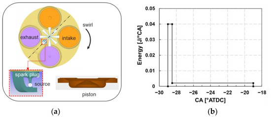
Figure 1.
(a) Schematic of cylinder head, injector, spark plug, and piston; (b) a two-stage energy distribution.
A 1.4 mm base mesh size was employed in the computational domain. A two-level sub-grid scale-based adaptive mesh refinement (AMR) on temperature and velocity gradients was utilized to automatically refine the mesh down to 0.35 mm. A one-level fixed embedding refinement resulting in a 0.7 mm mesh size was permanently imposed on the piston and cylinder head to accurately simulate flow near these boundaries; a two-level conical area of fixed embedding, leading to 0.35 mm mesh size, was specified around the injector to better predict the spray dynamics. Additionally, when simulating spark assistance, a three-level spherical area of fixed embedding (i.e., 0.175 mm mesh size) was used to precisely model the flow around the spark plug. The mesh refinement study can be found in earlier works [26,27,28].
Note that the boundary and initial conditions utilized in the closed-cycle simulations were procured from a one-dimensional (1D) GT-Power physical model. 3D CFD model validation against GCI engine experiments at cold idle was reported and discussed in [23].
2.5. Optimization Workflow
In the current study, a DoE/RSM optimization method was used. It utilizes statistical models to build proper response surfaces for optimization and has been employed in many applications [32,33,34,35,36,37,38]. The general optimization workflow is described as follows.
First, pre-DoE studies were performed to identify key design parameters and relevant design ranges. Next, a high-dimensional design space with multiple design parameters was carefully constructed and filled. Subsequently, CFD simulations of all space-filled design cases were performed, with the key performance results used as inputs to establish the RSMs. Finally, the top-ranked design candidates were found via the RSM-based optimization approach and validated in CFD analysis. The details of each step of CFD-DoE guided optimization are reported in a recent publication [39]. The specific space-filling method and RSM approach used in this work to achieve the best design will be discussed in the next section.
3. Results and Discussion
3.1. Overview of Previous Pre-DoE Spark Assistance Studies
In earlier pre-DoE studies by the authors [27,28], the effects of various design variables on spark-assisted GCI combustion during cold idle operations were studied in detail. To recap briefly, Figure 2 compares one case without spark assistance (w/o SP) and another with spark plug assistance (w/SP). The fuel droplet distribution and the flame volume development were presented for the two cases over a range of crank angles after SOI2nd. It was observed that the onset of ignition was much delayed (at 5°ATDC) for the w/o SP case. In contrast, for the w/ SP case, ignition occurred earlier (at −15°ATDC) near the spark plug region, leading to faster spray breakup and fuel vaporization. Therefore, the combustion process was further accelerated.
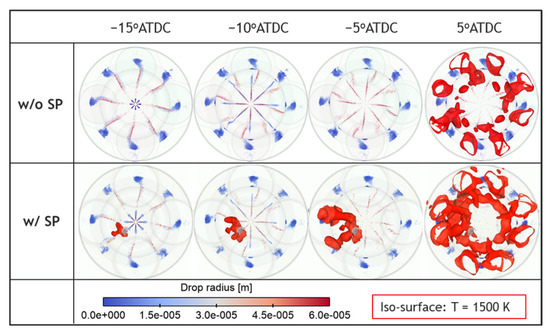
Figure 2.
In-cylinder fuel droplet distribution and flame volume development in two cases (w/o SP and w/SP) under cold idle operation in an HD GCI engine.
Generally, when a spark plug was used, an early ignition occurred near the spark plug, and the combustion efficiency of the case with spark plug assistance was found to increase by 11% compared to the case without it. Other studies [40,41,42] have also demonstrated the effectiveness of spark assistance in enhancing engine combustion performance under cold-starting conditions.
An in-depth pre-DoE analysis of the seven variables related to fuel spray patterns and injection strategies was conducted in Ref. [28]. Figure 3 highlights the relative significance of each design parameter on engine combustion efficiency (ŋc). Combustion efficiency ranges from maximum to minimum values for each design variable. The black and blue dashed lines indicate the baseline combustion efficiencies without and with spark assistance, respectively, to highlight how much improvement in combustion efficiency could be gained. Overall, the design variables that showed the strongest sensitivity were the number of injector nozzles, SOI1st, and the fuel split ratio. A relatively high percentage increase in combustion efficiency was obtained as SOI2nd varied. Other variables, such as injector clocking and spray inclusion angle, were found to be ineffective in influencing combustion characteristics.
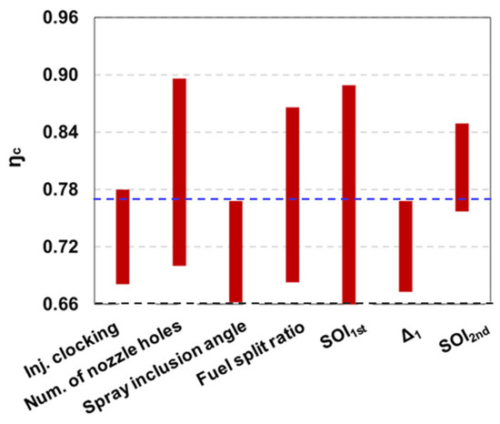
Figure 3.
Effects of different design variables on combustion efficiency (ŋc) under a spark-assisted cold idle operation in an HD GCI engine.
3.2. DoE/RSM Based Design Optimization
With a good understanding gained from the aforementioned studies, five main design variables—fuel split ratio, number of nozzle holes, SOI1st, Δ1 (dwell time between spark timing (ST) and SOI1st), and Δ2 (dwell time between pilot and main injections, viz., difference between SOI2nd and end of the first injection (EOI1st))—were selected for the DoE analysis. The design range for each variable is listed in Table 5. The reasons for including Δ1 as a design variable are that spark timing is critical to flame formation and development, and local fuel–air mixing and subsequent combustion depend on the dwell time between ST and SOI1st [27,28].
Table 5.
Design variables and ranges for DoE.
150 designs were generated using Sobol sequence [43] in CAESES software. This sampling method aims to randomly distribute the samples throughout the entire hyperspace. The four two-dimensional (2D) design space is graphed in Figure 4. The sampling method provided robust control over the distribution in the design space, and all data points were evenly distributed.
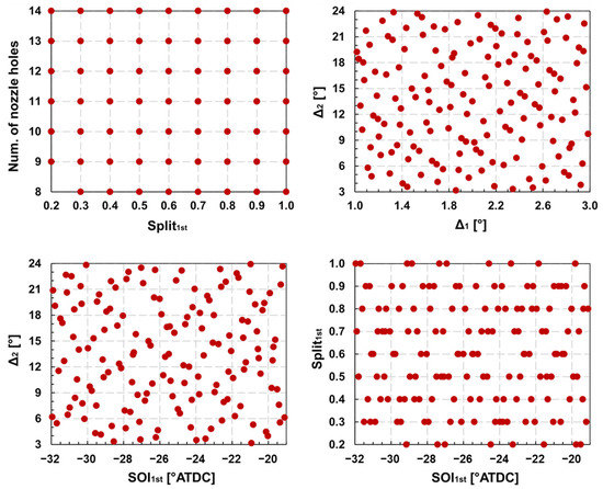
Figure 4.
Design points selected by using the Sobol sequence space-filling method.
Combustion efficiency (ŋc), maximum rate of pressure rise (MPRR), and NOx emissions were chosen as the three most important indicators for evaluating the design candidates. A merit function in Equation (1) was formulated. The baseline combustion efficiency (ŋc) was 76%, and the target MPRR and NOx were 10 bar/CAD and 6 g/kWh, respectively. In this study, the RSM was fitted and optimized through the interpolating recmultiquadric radial basis function (RBF) method [44] in the MATLAB-Based Calibration (MBC) toolbox. Figure 5 shows an example of the response surfaces of combustion efficiency (ŋc) and NOx emissions with respect to the number of nozzle holes and SOI1st. It was noted that the number of injector nozzles and SOI1st were the more influential factors for combustion efficiency and NOx.
where
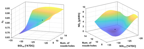
Figure 5.
Sample response surfaces of combustion efficiency (ηc) and NOx emissions with respect to SOI1st and the number of nozzle holes.
After identifying the optimal fuel spray pattern and injection strategies, they were validated in the CFD analysis. The best case from RSM optimization (RSM-best) provided good agreement against the CFD analysis results. The relative errors between the RSM-predicted and CFD-simulated combustion efficiency (ŋc) and NOx emissions were small (0.5% in ŋc and 1.6% in NOx). Table 6 compares the baseline case and the RSM-best case (CFD validated) in terms of design and objective variables. The RSM-best case showed a 17 percentage point improvement in combustion efficiency (ŋc) at the cost of a moderate increase in NOx compared to the baseline case. The merit value in the RSM-best case was also much larger than that in the baseline case. Figure 6 presents a comparison of the global combustion characteristics between the baseline and optimized cases. The RSM-best case clearly had a higher peak in-cylinder pressure, a stronger apparent heat release rate (AHRR), a more advanced start of combustion (SOC), and a shorter combustion duration, contributing to enhanced combustion efficiency, as shown in Table 6.
Table 6.
Comparison of baseline and RSM-best performance cases.
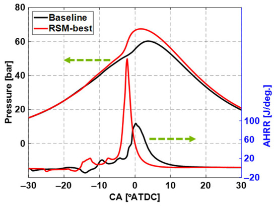
Figure 6.
Comparison of in-cylinder pressure and apparent heat release rate (AHRR) between baseline and RSM-best cases.
Furthermore, Figure 7 shows the local flame kernel growth and the distributions of the in-cylinder flow and equivalence ratio (Φ) fields near the spark gap between the two cases. For the baseline case, it was seen that the fuel spray plume was carried by the flow toward the upper part of the spark plug electrode, causing the flame kernel to be partially suppressed. However, in the RSM-best case, the flame kernel was continually developed and propagated with a proper mixture surrounding the spark plug. Therefore, it drove a faster and more robust ignition process.
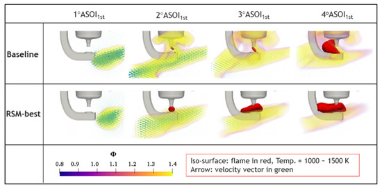
Figure 7.
Comparison of local flame development and the distributions of in-cylinder flow and equivalence ratio (Φ) fields near spark gap between baseline and RSM-best cases.
3.3. Sensitivity Analysis
Figure 8 shows a heatmap for the five individual design variables and the three objective variables. The correlation coefficient (ρij) was utilized to evaluate the strength of the relationship between each design parameter and each objective variable. The correlation coefficient (ρij) was calculated based on the covariance of the two selected variables and their standard deviations, as shown in Equation (2). Note that the correlation considered the combination of these design factors concurrently.
where
- is the covariance of variables i and j
- and are standard deviations of variable i and j, respectively

Figure 8.
Correlations between five design parameters and three objective variables.
Figure 8.
Correlations between five design parameters and three objective variables.

As seen from the heatmap, the correlation coefficient (ρij) varied between 0 and 0.45 (blue to green), with green highlighting strong correlations, while blue representing weak correlations. It suggested that overall, split ratio, number of nozzle holes, and SOI1st were the most influential factors in the objectives. Since particular emphasis was on improving ignition and combustion, the most sensitive design variables on combustion efficiency (ŋc) were the number of nozzle holes, SOI1st, and split ratio (split1st).
When analyzing the sensitivity and behavior of each of these three top-ranked design variables on combustion performance, the other variables were maintained at levels similar to those in the RSM-best case. Similar to previous studies [28], in general, the increase in the number of nozzles resulted in higher combustion efficiency (ŋc), MPRR, and NOx emissions, as shown in the 2D response surface plot in Figure 9a. Figure 9b provides the in-cylinder pressure and AHRR in three different numbers of nozzles (9-, 11-, and 14-hole). A consistent trend with the response surface plot was observed, showing that a larger number of nozzle holes led to higher peak in-cylinder pressure and AHRR, earlier SOC, more advanced combustion phasing, and shorter combustion duration. The lower spray momentum in the larger number of nozzles resulted in the weaker spray–spark plug interaction and helped the flame kernel develop and propagate, facilitating earlier ignition. Moreover, since the swirl motion effect was stronger in the larger number of nozzles, better fuel–air mixing led to enhanced combustion and higher combustion efficiency.
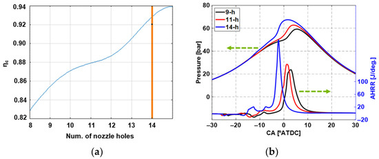
Figure 9.
(a) The 2D response surface between combustion efficiency (ŋc) and the number of nozzle holes; (b) in-cylinder pressure and apparent heat release rate (AHRR) in different numbers of nozzles.
SOI1st had notable effects on both early ignition and late main combustion. When advancing or retarding SOI1st too much, the environment for flame kernel formation and the mixing process became unfavorable, as shown in the 2D response surface in Figure 10a, leading to lower combustion efficiency (ŋc). Within the SOI1st range studied in the current work, SOI1st of −26° ATDC showed higher combustion efficiency. This was further supported by Figure 10b, in which the comparison between SOI1st of −26° and −24° ATDC indicated a higher peak in-cylinder pressure, a stronger AHRR, and more advanced SOC and combustion phasing in SOI1st of −26° ATDC.
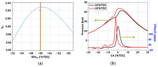
Figure 10.
(a) The 2D response surface between combustion efficiency (ŋc) and the start of the first fuel injection timing (SOI1st); (b) in-cylinder pressure and apparent heat release rate (AHRR) in different SOI1st.
The fuel split ratio was also profound because it affected the injected fuel quantity and injection durations during both the pilot and main injections. This, in turn, affected how strong the spray momentum was and how well the air and fuel mixed [28]. From the 2D response surface in Figure 11a, with either an excessive decrease or increase in split1st, combustion efficiency (ŋc) deteriorated. When the fuel quantity during the first injection decreased too much, fuel–air mixing was not beneficial for early flame development. On the other hand, the rich mixture suppressed flame growth and propagation when the pilot fuel injection quantity increased excessively, leading to lower combustion efficiency. In the current study, the best performance was observed in split1st = 0.33, as in the selective cases in Figure 11b, where a higher maximum in-cylinder pressure and a stronger AHRR were found in split1st = 0.33 than in split1st = 0.8.
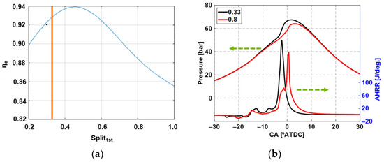
Figure 11.
(a) The 2D response surface between combustion efficiency (ŋc) and fuel split ratio (split1st); (b) in-cylinder pressure and apparent heat release rate (AHRR) in different fuel split ratios.
4. Conclusions
In this study, CFD-guided design optimization was performed within a spray-guided spark assistance framework under gasoline compression ignition (GCI) cold operations. The DoE response surface model (RSM) optimization approach was utilized to optimize the fuel spray pattern and injection strategies. The main design variables included the number of injector nozzles, fuel injection quantities and timings, and spark timing. The key performance parameters were engine combustion efficiency (ŋc), maximum rate of pressure rise (MPRR), and engine-out NOx emissions. The best design candidate was identified via the RSM-based optimization process and validated against CFD simulations. The engine combustion performance results from the best design showed significantly improved combustion efficiency (~93%) over the baseline case (76%) while satisfying MPRR and NOx emission constraints (MPRR < 5 bar/CAD and NOx < 4.5 g/kWh). Based on the sensitivity analysis, it was found that the number of nozzle holes, SOI1st, and fuel split ratio were the most influential design variables on combustion performance.
Despite its advantages, spray-guided spark assistance may have some limitations, such as durability issues and soot emission formation due to spray impingement on the spark plug. By utilizing the same methodology, further efforts will be made on a wall-guided spark assistance approach, where the spark plug is located farther away from the injector, to develop operating strategies to maximize the GCI’s combustion performance and reduce emissions formation during cold operating conditions.
Author Contributions
Conceptualization, Y.Z., Y.P. and A.Z.; methodology, Y.Z., Y.P. and A.Z.; validation, L.Z.; formal analysis, L.Z.; investigation, L.Z. and M.M.A.; data curation, L.Z.; writing—original draft preparation, L.Z.; writing—review and editing, Y.Z., Y.P. and M.M.A.; supervision, Y.Z., Y.P. and M.M.A.; project administration, Y.Z. and Y.P. All authors have read and agreed to the published version of the manuscript.
Funding
This research received no external funding.
Institutional Review Board Statement
Not applicable.
Informed Consent Statement
Not applicable.
Data Availability Statement
Not applicable.
Acknowledgments
This research was financially supported by Aramco Americas: Aramco Research Center–Detroit.The authors would like to acknowledge the high-performance computing resources at Aramco Americas Research Centers and the computing resources provided on the Blues cluster, which is operated by the Laboratory Computing Resource Center at Argonne National Laboratory.
Conflicts of Interest
The authors declare no conflict of interest.
Nomenclature
| ATDC | After top dead center |
| ŋc | Combustion efficiency |
| Φ | Equivalence ratio |
| SOI1st | Start of the first fuel injection |
| SOI2nd | Start of the second fuel injection |
| EOI1st | End of the first fuel injection |
| ST | Spark timing |
| split1st | Fuel split ratio |
| Δ1 | Dwell time between spark timing and SOI1st |
| Δ2 | Dwell time between pilot and main injections |
| ρij | Correlation coefficient of variables i and j |
| COVij | Covariance of variables i and j |
| σi, σj | Standard deviations of variable i and j, respectively |
References
- Andrae, J.; Brinck, T.; Kalghatgi, G. HCCI Experiments with Toluene Reference Fuels Modeled by a Semidetailed Chemical Kinetic Model. Combust. Flame 2008, 155, 696–712. [Google Scholar] [CrossRef]
- An, Y.; Jaasim, M.; Raman, V.; Pérez, F.E.H.; Sim, J.; Chang, J.; Im, H.G.; Johansson, B. Homogeneous Charge Compression Ignition (HCCI) and Partially Premixed Combustion (PPC) in Compression Ignition Engine with Low Octane Gasoline. Energy 2018, 158, 181–191. [Google Scholar] [CrossRef]
- Epping, K.; Aceves, S.; Bechtold, R.; Dec, J.E. The Potential of HCCI Combustion for High Efficiency and Low Emissions; SAE Technical Paper 2002-01-1923; SAE International: Warrendale, PA, USA, 2002. [Google Scholar] [CrossRef]
- Noehre, C.; Andersson, M.; Johansson, B.; Hultqvist, A. Characterization of Partially Premixed Combustion; SAE Technical Paper 2006-01-3412; SAE International: Warrendale, PA, USA, 2006. [Google Scholar] [CrossRef]
- Cho, K.; Han, M.; Wagner, R.M.; Sluder, C.S. Mixed-Source EGR for Enabling High Efficiency Clean Combustion Modes in a Light-Duty Diesel Engine. SAE Int. J. Engines 2009, 1, 457–465. [Google Scholar] [CrossRef]
- Kokjohn, S.; Hanson, R.; Splitter, D.; Kaddatz, J.; Reitz, R.D. Fuel Reactivity Controlled Compression Ignition (RCCI) Combustion in Light- and Heavy-Duty Engines. SAE Int. J. Engines 2011, 4, 360–374. [Google Scholar] [CrossRef]
- Prikhodko, V.Y.; Curran, S.J.; Barone, T.L.; Lewis, S.A.; Storey, J.M.; Cho, K.; Wagner, R.M.; Parks, J.E. Emission Characteristics of a Diesel Engine Operating with In-Cylinder Gasoline and Diesel Fuel Blending. SAE Int. J. Fuels Lubr. 2010, 3, 946–955. [Google Scholar] [CrossRef]
- Roberts, J.; Kokjohn, S.; Hou, D.; Huang, Y. Performance of Gasoline Compression Ignition (GCI) with On-Demand Reactivity Enhancement over Simulated Drive Cycles; SAE Technical Paper 2018-01-0255; SAE International: Warrendale, PA, USA, 2018. [Google Scholar] [CrossRef]
- Reitz, R.D.; Duraisamy, G. Review of High Efficiency and Clean Reactivity Controlled Compression Ignition (RCCI) Combustion in Internal Combustion Engines. Prog. Energy Combust. Sci. 2015, 46, 12–71. [Google Scholar] [CrossRef]
- Kalghatgi, G.T.; Risberg, P.; Ångström, H. Partially Pre-mixed Auto-Ignition of Gasoline to Attain Low Smoke and Low NOx at High Load in a Compression Ignition Engine and Comparison with a Diesel Fuel; SAE Technical Paper 2007-01-0006; SAE International: Warrendale, PA, USA, 2007. [Google Scholar] [CrossRef]
- Weall, A.; Collings, N. Investigation into Partially Premixed Combustion in a Light-Duty Multi-cylinder Diesel Engine Fuelled Gasoline and Diesel with a Mixture of; SAE Technical Paper 2007-01-4058; SAE International: Warrendale, PA, USA, 2007. [Google Scholar] [CrossRef]
- Sellnau, M.; Sinnamon, J.; Hoyer, K.; Husted, H. Gasoline Direct Injection Compression Ignition (GDCI)—Diesel-Like Efficiency with Low CO2 Emissions. SAE Int. J. Engines 2011, 4, 2010–2022. [Google Scholar] [CrossRef]
- Cho, K.; Latimer, E.; Lorey, M.; Cleary, D.J.; Sellnau, M. Gasoline Fuels Assessment for Delphi’s Second Generation Gasoline Direct-Injection Compression Ignition (GDCI) Multi-cylinder Engine. SAE Int. J. Engines 2017, 10, 1430–1442. [Google Scholar] [CrossRef]
- Dec, J.E.; Dernotte, J.; Ji, C. Increasing the Load Range, Load-to-Boost Ratio, and Efficiency of Low-Temperature Gasoline Combustion (LTGC) Engines. SAE Int. J. Engines 2017, 10, 1256–1274. [Google Scholar] [CrossRef]
- Cho, K.; Zhao, L.; Ameen, M.; Zhang, Y.; Pei, Y.; Moore, W.; Sellnau, M. Understanding Fuel Stratification Effects on Partially Premixed Compression Ignition (PPCI) Combustion and Emissions Behaviors; SAE Technical Paper 2019-01-1145; SAE International: Warrendale, PA, USA, 2019. [Google Scholar] [CrossRef]
- Zhang, Y.; Voice, A.; Tzanetakis, T.; Traver, M.; Cleary, D. An Evaluation of Combustion and Emissions Performance with Low Cetane Naphtha Fuels in a Multicylinder Heavy-Duty Diesel Engine. J. Eng. Gas Turbines Power 2016, 138, 102805. [Google Scholar] [CrossRef]
- Chang, J.; Kalghatgi, G.; Amer, A.; Adomeit, P.; Rohs, H.; Heuser, B. Vehicle Demonstration of Naphtha Fuel Achieving Both High Efficiency and Drivability with EURO6 Engine-Out NOx Emission. SAE Int. J. Engines 2013, 6, 101–119. [Google Scholar] [CrossRef]
- Kalghatgi, G.T.; Risberg, P.; Ångström, H.-E. Advantages of Fuels with High Resistance to Auto-Ignition in Late-Injection, Low-Temperature, Compression Ignition Combustion; SAE Technical Paper 2006-01-3385; SAE International: Warrendale, PA, USA, 2006. [Google Scholar] [CrossRef]
- Manente, V.; Zander, C.-G.; Johansson, B.; Tunestal, P.; Cannella, W. An Advanced Internal Combustion Engine Concept for Low Emissions and High Efficiency from Idle to Max Load Using Gasoline Partially Premixed Combustion; SAE Technical Paper 2010-01-2198; SAE International: Warrendale, PA, USA, 2010. [Google Scholar] [CrossRef]
- Zhang, Y.; Kumar, P.; Traver, M.; Cleary, D. Conventional and Low Temperature Combustion Using Naphtha Fuels in a Multi-Cylinder Heavy-Duty Diesel Engine. SAE Int. J. Engines 2016, 9, 1021–1035. [Google Scholar] [CrossRef]
- Zhang, Y.; Kumar, P.; Pei, Y.; Traver, M.; Cleary, D. An Experimental and Computational Investigation of Gasoline Compression Ignition Using Conventional and Higher Reactivity Gasolines in a Multi-cylinder Heavy-Duty Diesel Engine; SAE Technical Paper 2018-01-0226; SAE International: Warrendale, PA, USA, 2018. [Google Scholar] [CrossRef]
- Rose, K.; Ariztegui, J.; Cracknell, R.; Dubois, T.; Hamje, H.; Pellegrini, L.; Rickeard, D.; Heuser, B.; Schnorbus, T.; Kolbeck, A. Exploring a Gasoline Compression Ignition (GCI) Engine Concept; SAE Technical Paper 2013-01-0911; SAE International: Warrendale, PA, USA, 2013. [Google Scholar] [CrossRef]
- Zhao, L.; Ameen, M.; Pei, Y.; Zhang, Y.; Kumar, P.; Tzanetakis, T.; Traver, M. Numerical Evaluation of Gasoline Compression Ignition at Cold Conditions in a Heavy-Duty Diesel Engine; SAE Technical Paper 2020-01-0778; SAE International: Warrendale, PA, USA, 2020. [Google Scholar] [CrossRef]
- Zhao, L.; Ameen, M.M.; Pei, Y.; Zhang, Y. The Effect of Fuel Properties on Inert Spray Characteristics under Compression Ignition Engine Conditions. In Proceedings of the ILASS-Americas 30th Annual Conference on Liquid Atomization and Spray Systems, Tempe, AZ, USA, 12–15 May 2019. [Google Scholar]
- Zhao, L.; Ameen, M.M.; Pei, Y.; Zhang, Y.; Traver, M.; Garcia-Oliver, J.; Vera-Tudela, W. Effect of Fuel Properties on Spray and Combustion Characteristics under Compression Ignition Engine Conditions. In Proceedings of the 11th US National Combustion Meeting, Pasadena, CA, USA, 24–27 March 2019. [Google Scholar]
- Zhao, L.; Pei, Y.; Zhang, Y.; Kumar, P.; Tzanetakis, T.; Traver, M.; Ameen, M. Numerical Evaluation of Spray-Guided Glow Plug Assistance on Gasoline Compression Ignition during Cold Idle Operation in a Heavy-Duty Diesel Engine. In Proceedings of the ASME Internal Combustion Engine Division Fall Technical Conference, Virtual, 4–6 November 2020. [Google Scholar] [CrossRef]
- Zhao, L.; Zhang, Y.; Pei, Y.; Zhang, A.; Traver, M.; Ameen, M. Numerical Evaluation of Spark Assisted Cold Idle Operation in a Heavy-Duty Gasoline Compression Ignition Engine; SAE Technical Paper 2021-01-0410; SAE International: Warrendale, PA, USA, 2021. [Google Scholar] [CrossRef]
- Zhao, L.; Zhang, Y.; Pei, Y.; Zhang, A.; Ameen, M.M. CFD-Guided Evaluation of Spark-Assisted Gasoline Compression Ignition for Cold Idle Operation. Sustainability 2021, 13, 13096. [Google Scholar] [CrossRef]
- Richards, K.J.; Senecal, P.K.; Pomraning, E. Converge Manual, Version 2.4; Convergent Science Inc.: Madison, WI, USA, 2018.
- Liu, Y.-D.; Jia, M.; Xie, M.-Z.; Pang, B. Enhancement on a Skeletal Kinetic Model for Primary Reference Fuel Oxidation by Using a Semidecoupling Methodology. Energy Fuels 2012, 26, 7069–7083. [Google Scholar] [CrossRef]
- Zhang, Y.; Pei, Y.; Tang, M.; Traver, M. A Computational Investigation of Piston Bowl Geometry and Injector Spray Pattern Effects on Gasoline Compression Ignition in a Heavy-Duty Diesel Engine. In Proceedings of the ASME Internal Combustion Engine Division Fall Technical Conference, Chicago, IL, USA, 20–23 October 2019. [Google Scholar] [CrossRef]
- Pei, Y.; Zhang, Y.; Kumar, P.; Traver, M.; Cleary, D.; Ameen, M.; Som, S.; Probst, D.; Burton, T.; Pomraning, E.; et al. CFD-Guided Heavy Duty Mixing-Controlled Combustion System Optimization with a Gasoline-Like Fuel. SAE Int. J. Commer. Veh. 2017, 10, 532–546. [Google Scholar] [CrossRef]
- Pei, Y.; Pal, P.; Zhang, Y.; Traver, M.; Cleary, D.; Futterer, C.; Brenner, M.; Probst, D.; Som, S. CFD-Guided Combustion System Optimization of a Gasoline Range Fuel in a Heavy-Duty Compression Ignition Engine Using Automatic Piston Geometry Generation and a Supercomputer. SAE Int. J. Adv. Curr. Pract. Mobil. 2019, 1, 166–179. [Google Scholar] [CrossRef]
- Probst, D.M.; Senecal, P.K.; Chien, P.Z.; Xu, M.X.; Leyde, B.P. Optimization and Uncertainty Analysis of a Diesel Engine Operating Point Using Computational Fluid Dynamics. J. Eng. Gas Turbines Power 2018, 140, 102806. [Google Scholar] [CrossRef]
- D’Ambrosio, S.; Ferrari, A. Potential of Double Pilot Injection Strategies Optimized with the Design of Experiments Procedure to Improve Diesel Engine Emissions and Performance. Appl. Energy 2015, 155, 918–932. [Google Scholar] [CrossRef]
- Rajamani, V.K.; Schoenfeld, S.; Dhongde, A. Parametric Analysis of Piston Bowl Geometry and Injection Nozzle Configuration Using 3D CFD and DoE; SAE Technical Paper 2012-01-0700; SAE International: Warrendale, PA, USA, 2012. [Google Scholar] [CrossRef]
- Hajireza, S.; Regner, G.; Christie, A.; Egert, M.; Mittermaier, H. Application of CFD Modeling in Combustion Bowl Assessment of Diesel Engines Using DoE Methodology; SAE Technical Paper 2006-01-3330; SAE International: Warrendale, PA, USA, 2006. [Google Scholar] [CrossRef]
- Styron, J.; Baldwin, B.; Fulton, B.; Ives, D.; Ramanathan, S. Ford 2011 6.7 L Power Stroke® Diesel Engine Combustion System Development; SAE Technical Paper 2011-01-0415; SAE International: Warrendale, PA, USA, 2011. [Google Scholar] [CrossRef]
- Pei, Y.; Zhang, A.; Pal, P.; Zhao, L.; Zhang, Y.; Som, S. Computational Fluid Dynamics–Guided Engine Combustion System Design Optimization Using Design of Experiments. In Artificial Intelligence and Data Driven Optimization of Internal Combustion Engines; Elsevier: Amsterdam, The Netherlands, 2022; pp. 103–123. [Google Scholar]
- Cracknell, R.; Bastaert, D.; Houille, S.; Châtelain, J.; Larguier, O.; Beaugé, Y.; Gente, F.; Nicolas, B.; Prevet, S.; Fandakov, A.; et al. Assessing the Efficiency of a New Gasoline Compression Ignition (GCI) Concept; SAE Technical Paper 2020-01-2068; SAE International: Warrendale, PA, USA, 2020. [Google Scholar] [CrossRef]
- La Rocca, A.; Macmillan, D.; Shayler, P.; Murphy, M.; Pegg, I. CFD Investigation on the Influence of In-Cylinder Mixture Distribution from Multiple Pilot Injections on Cold Idle Behaviour of a Light Duty Diesel Engine; SAE Technical Paper 2014-01-2708; SAE International: Warrendale, PA, USA, 2014. [Google Scholar] [CrossRef]
- Naganuma, K.; Tanaka, K.; Ito, T.; Kobashi, Y. Study for Ignition Characteristics and Potential of Gasoline Autoignition Combustion with Spark Assist; SAE Technical Paper 2019-01-2317; SAE International: Warrendale, PA, USA, 2019. [Google Scholar] [CrossRef]
- Sobol’, I.Y.M. On the Distribution of Points in a Cube and the Approximate Evaluation of Integrals. Comput. Math. Math. Phys. 1967, 7, 784–802. [Google Scholar] [CrossRef]
- Zhang, Y.; Sellnau, M. A Computational Investigation of PPCI-Diffusion Combustion Strategy at Full Load in a Light-Duty GCI Engine. SAE Int. J. Adv. Curr. Pract. Mobil. 2021, 3, 1757–1775. [Google Scholar] [CrossRef]


Disclaimer/Publisher’s Note: The statements, opinions and data contained in all publications are solely those of the individual author(s) and contributor(s) and not of MDPI and/or the editor(s). MDPI and/or the editor(s) disclaim responsibility for any injury to people or property resulting from any ideas, methods, instructions or products referred to in the content. |
© 2023 by the authors. Licensee MDPI, Basel, Switzerland. This article is an open access article distributed under the terms and conditions of the Creative Commons Attribution (CC BY) license (https://creativecommons.org/licenses/by/4.0/).