Article

Medium Rock-Soil Temperature Distribution Characteristics at Different Time Scales and New Layout Forms in the Application of Medium-Deep Borehole Heat Exchangers

1
Key Laboratory of Coal Resources Exploration and Comprehensive Utilization, Ministry of Natural Resources, Shaanxi Coal Geology Group Co., Ltd., Xi’an 710026, China
2
School of Mechanical Engineering, Xi’an Jiaotong University, Xi’an 710049, China
3
School of Human Settlements and Civil Engineering, Xi’an Jiaotong University, Xi’an 710049, China
4
Shaanxi Zhongmei New Energy Co., Ltd., Xi’an 710054, China
*
Authors to whom correspondence should be addressed.
Energies 2023, 16(19), 6970; https://doi.org/10.3390/en16196970
Submission received: 29 August 2023 / Revised: 27 September 2023 / Accepted: 28 September 2023 / Published: 6 October 2023
(This article belongs to the Section H: Geo-Energy)

Abstract

:
Medium-deep borehole heat exchangers (MBHEs) have received increasing attention with respect to building heating. To avoid the thermal interference of adjacent MBHEs, the temperature distribution characteristics of medium-deep rock soil were investigated in this work. The evolution of the maximum rock-soil thermal affected radius (MTAR) over a full lifecycle was analyzed. The results showed that the rock-soil thermal affected area (RTAA) continuously expanded in both the radial and vertical directions when the MBHE continuously extracted geothermal energy during a heating season. The factors of the thermal extraction load, fluid velocity, geothermal gradient, and pipe length, impacted the RTAA in the vertical direction, while rock-soil thermal conductivity affected the RTAA in both the radial and vertical directions. Furthermore, the thermal affected radius (TAR) in deeper formations was larger, reaching even 96 m, such that thermal interference between adjacent MBHEs was more likely to occur. The MTAR in shallow formations was limited to 20 m. Consequently, a new layout form, achieved by inclining the borehole, was proposed to increase the distance between adjacent MBHEs in deep formations. The recommended incline angle was equal to or larger than four times the TAR angle. This work provides a scientific reference for promoting the application of multiple MBHE arrays.

1. Introduction

With energy and environmental issues becoming increasingly prominent, the aims of peak carbon and carbon neutralization have been established by many countries [1]. Energy structure adjustment is occurring throughout all walks of life [2,3,4]. There is a trend to exploit renewable energy sources instead of traditional fossil fuel energy. Space heating is traditionally achieved using coal and natural gas, but nowadays the use of geothermal energy is gradually playing a more important role in order to depollute the atmosphere and decarbonize [5,6,7].
According to ground layer depth, geothermal energy resources can be classified into shallow geothermal energy (<200 m), medium-deep geothermal energy (200~3000 m), and deep geothermal energy (>3000 m). Shallow and medium-deep geothermal energy have been successfully applied in space heating [8,9,10,11,12,13], whereas deep geothermal energy is more commonly used for power generation due to its high energy grade [14,15,16]. With a growing awareness of the need for underground environment protection, the geothermal heating technique of indirect heat transfer has been widely promoted, especially in the form of shallow borehole heat exchangers (SBHEs) [9,10]. However, SBHE systems need a large ground occupation area, which is not preferred in densely populated areas. Medium-deep borehole heat exchangers (MBHEs), usually with depths of greater than or equal to 2000 m, have been proposed due to their lower land demand, and are used in heating demonstration projects [11,12,13]. In view of their advantages of environmental friendliness and high heating energy efficiency, multiple MBHE arrays have been applied in some heating projects [17,18].
In earlier studies, field tests [19,20,21] and numerical simulations were carried out for a single MBHE in order to ensure its thermal extraction capacity. Due to the difference from the field test results (for example, the measured thermal extraction capacity of the single MBHE ranged from 158~288 kW [20]), the effects of the influencing factors, including the operating parameters (such as the inlet temperature [22,23] and flow velocity [24,25,26]), geological parameters (such as the rock-soil thermal conductivity [27,28], rock-soil heat capacity [29], and the geothermal gradient [30,31]), and the design parameters (such as the pipe depth [32], pipe diameter [33], and inner pipe thermal conductivity [34]) on the thermal extraction capacity of the MBHE were investigated using numerical analysis, which contributed an accurate evaluation of the thermal extraction capacity. However, relevant studies found that thermal interference exists in MBHE arrays [18,35,36]. Cai et al. [18] initially analyzed the thermal performance of five MBHEs with a maximum adjacent spacing of 30 m, according to practical heating engineering, and found that thermal interactions existed among the MBHEs, which had about 12% shifted thermal load. Based on this research [18], Cai et al. [35] investigated the effects of soil thermal properties on the thermal performance of multiple MBHE arrays and optimized the system layouts. Zhang et al. [36] proposed a superposition dimension reduction algorithm to rapidly calculate the fluid temperature of multiple MBHE arrays. The optimal design spacing of MBHE arrays could be ensured by continuously computing the fluid temperatures in the conditions of various spacings and comparing their differences.
The number of MBHEs utilized can range from single to multiple arrays. The attendant problem is how to avoid thermal interference between adjacent MBHEs, in order to maintain high energy efficiency and stability of heating. To ensure a rational spacing distance, the key issue of the temperature distribution characteristics of medium-deep rock soil needed to be solved to determine the maximum rock-soil thermal affected area (RTAA). Le Lous et al. [29] analyzed the effects of the heat extraction load, inlet temperature, and geological parameters on the RTAA. Geological parameters had a more obvious effect. Groundwater also impacts the thermal performance of MBHEs, but the extent depends on the aquifer thickness, aquifer depth, and groundwater velocity [28]. The RTAA is larger in the direction of groundwater [37]. Natural convection within an aquifer significantly impacts the thermal performance when the MBHE has a shorter length [38]. Furthermore, Song et al. [26] investigated the evolution of the medium-deep rock-soil impact scope during a single year. The maximum impact scope increased from 13 m at the end of the heating season to 27 m at the end of the year. Zhang et al. [36] conducted an analysis on long-term dynamic heat transfer of multiple MBHEs. A borehole spacing of 50–60 m was recommended. Brown et al. [39] analyzed the optimal borehole spacing of MBHEs in line arrays and square arrays, indicating that the latter requires a larger borehole spacing. Cai et al. [35] compared the thermal performance of MBHEs between the different arrangement geometries, including a single line layout, circle layout, and polyline layout. The results showed that the single line layout is preferred for a higher thermal performance. As mentioned above, there are two research methods to analyze how to avoid thermal interference between adjacent boreholes. One is ensuring the maximum thermal affected radius (MTAR) of rock soil; the MTAR is set as the optimal borehole spacing. On the other hand, the optimal spacing can be ensured when the fluid temperatures of MBHE arrays hardly change by continuously changing the borehole spacing.
As mentioned above, many of the influencing factors impact the RTAA [29]. Most research in this area has been carried out based on typical conditions. The operation mode of MBHEs is extracting the geothermal energy in the heating season and stopping geothermal extraction in the non-heating season. The authors of [29] did not take this into account. The temperature distribution characteristics of medium-deep rock soil in the whole lifecycle have not yet been fully clarified. Although Cai et al. [35] investigated the distribution patterns of the maximum RTAA during a 15-year operation period, the thermal performance of MBHEs had not reached a quasi-steady state in that research according to [37], indicating the mentioned maximum RTAA may still change in later operating years. Brown et al. [39] conducted RTAA research of MBHE with depth of 922 m for 20 years and a heating load of 50 kW (54.2 W/m) was set. For the MBHE with a longer depth (such as 2000~3000 m) or/and a higher heating load (usually over 100 W/m), the effects on the RTAA should be further analyzed. Additionally, previous research has only concentrated on the MTAR. For example, Zhang et al. [36] concluded that the spacing between adjacent MBHEs comes to 50~60 m, which is 10 times larger than the spacing between adjacent SBHEs [10]. In this case, multiple MBHE arrays will occupy a large amount of ground area, which is detrimental to their application in densely populated areas. Thus, there is an urgent need to decrease the ground surface occupation of multiple MBHE arrays.
Based on an analysis of previous studies, the medium-deep rock-soil temperature distribution characteristics in different time scales were investigated in this work. The aim was to clearly demonstrate the main RTAA in the whole lifecycle, and effectively avoid thermal interference in the main RTAA. By proposing a numerical model of heat transfer between the MBHE and surrounding rock soil, the effects of influencing factors, including the thermal extraction load, operating parameters, geological parameters, and design parameters on the medium-deep rock-soil temperature distribution were analyzed, whilst ensuring consideration of the main factors which largely impact the maximum thermal affected radius (MTAR). Combining the operation mode for extracting geothermal energy in the heating season and stopping geothermal extraction in the non-heating season, the effective MTAR of the full lifecycle was analyzed and determined. Simultaneously, to reduce the ground surface occupation of multiple MBHE arrays, a new layout was proposed in this study according to the medium-deep rock-soil temperature distribution characteristics. The conclusions of this work could guide the spacing design and optimization of the layout in the application of MBHEs.

2. Methodology

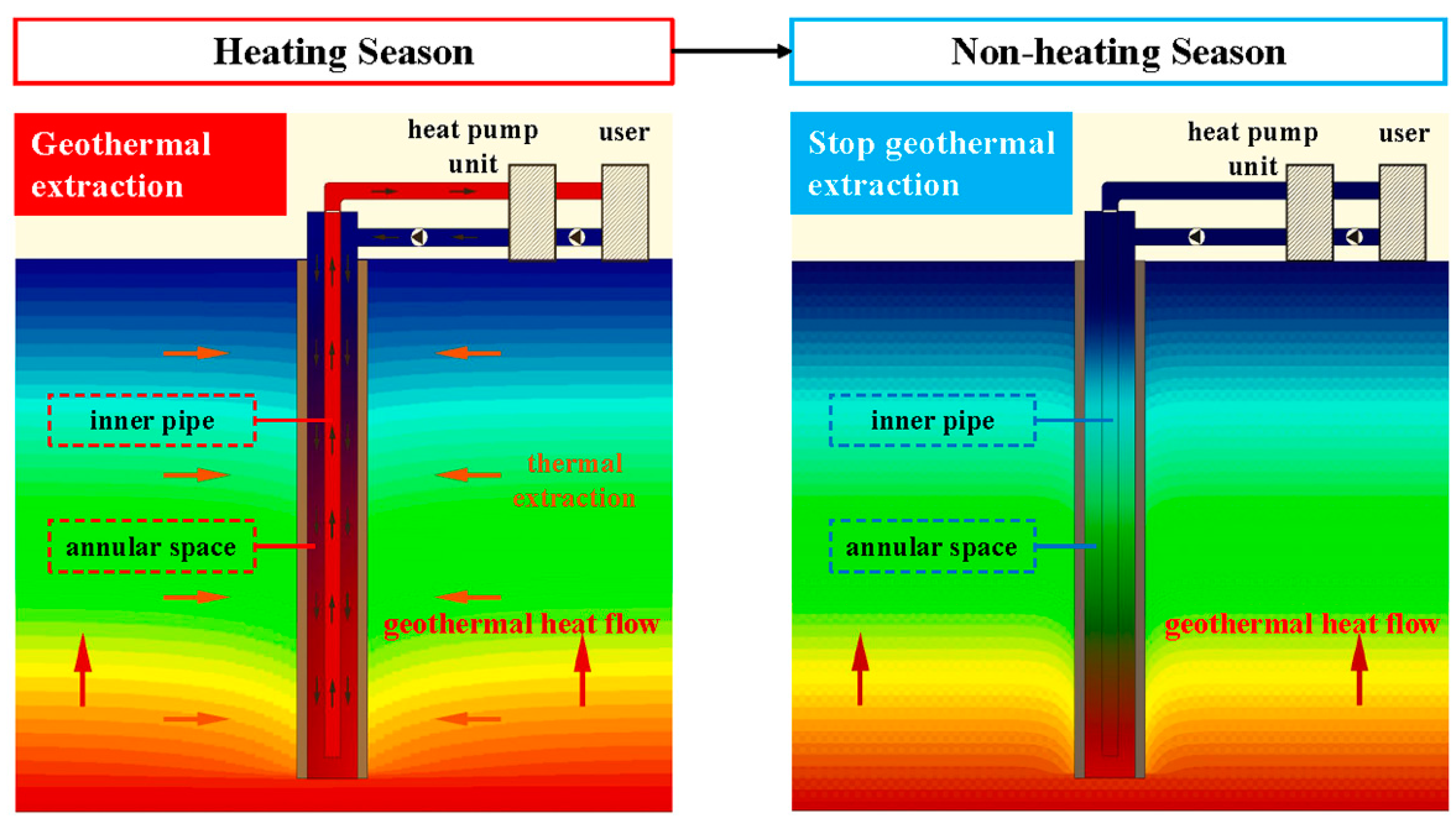
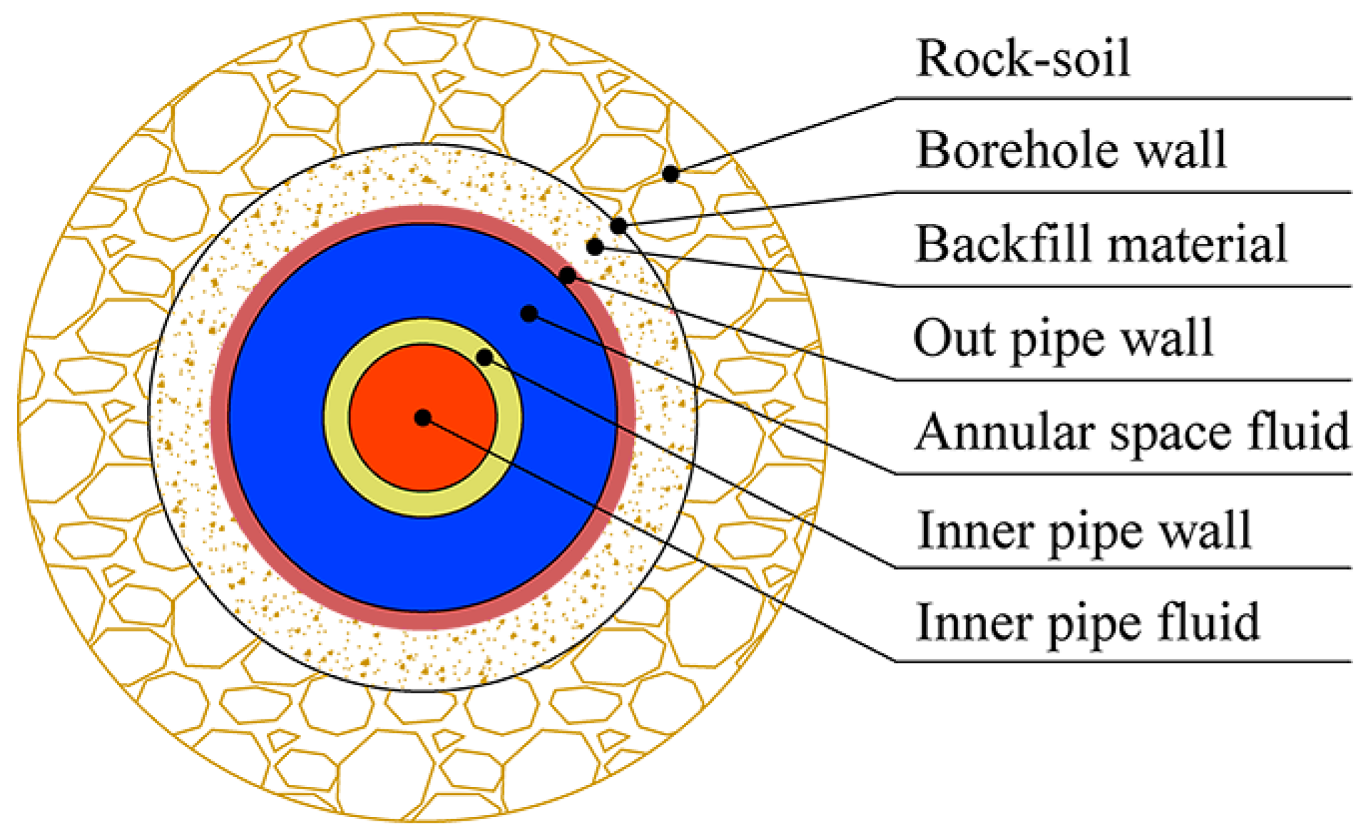
2.1. Heat Transfer between the MBHE and Rock Soil

Due to the high energy grade of medium-deep rock soil, an MBHE usually extracts geothermal energy for building heating in the heating season and stops running in the non-heating season (Figure 1). During the heating season, low temperature fluid flows downwards in annular space and absorbs the heat from the surrounding rock soil, where the fluid temperature increases but the rock-soil temperature decreases. Then, the heated fluid is transported by an inner pipe to the ground surface. The energy contained in the high-temperature fluid is utilized by a heat pump for building heating. During the non-heating season, the fluid is still in the MBHE, thus there is no thermal extraction from the medium-deep rock soil. The rock-soil temperature recovers under the effect of heat supply from geothermal heat flow. Figure 2 shows the positional relationship between the MBHE and the surrounding rock soil.

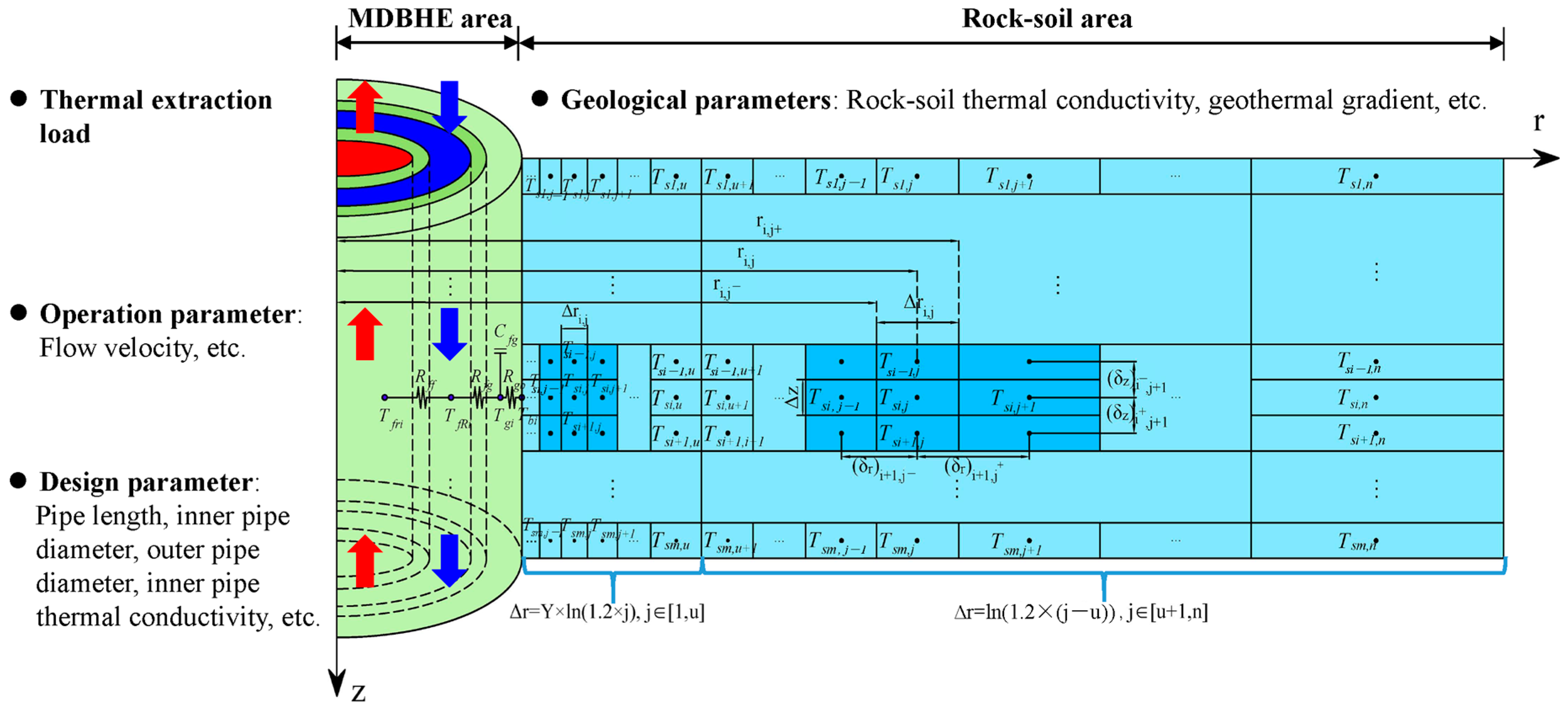
2.2. Numerical Simulation and Analysis Method

2.2.1. Balance Equations in the Numerical Model

The numerical model was generated based on a 1D MBHE element coupled with a 2D rock-soil element. Some assumptions were made: (1) only pure heat conduction exists in medium-deep rock soil; (2) the ground surface temperature is constant because it hardly impacts the MBHE performance; and (3) the thermal properties of the fluid, backfill material, pipe, and rock soil do not change with the variation of temperature.
Four energy balance equations were needed, as follows:
Energy equations of inner pipe fluid:
T f r t + ( V f r · T f r ) z = k ff ( T f an T f r ) ρ f A r c pf
where Tfr, Vfr, Tfan, kff, ρf, Ar, and cpf are the fluid temperature in the inner pipe, fluid flow velocity in the inner pipe, fluid temperature in the annular space, heat transfer coefficient between fluids in the inner pipe and annular space, fluid density, cross-section area of the inner pipe, and fluid heat capacity, respectively.
Energy equations of annular space fluid:
T f an t + ( V f an · T f an ) z = k fg ( T g T f an ) ρ f A an c pf k ff ( T f an T f r ) ρ f A an c pf
where Vfan, kfg, Tg, and Aan are the fluid flow velocity in the annular space, heat transfer coefficient between fluids in the annular space and backfill material, backfill material temperature, and cross-section area of the annular space, respectively.
Energy equations of the backfill material:
T g t = k fg ( T f an T g ) ρ g A g c pg + k gb ( T b T g ) ρ g A g c pg
where ρg, Ag, cpg, kgb, and Tb are the backfill material density, cross-section area of the backfill material, backfill material heat capacity, heat transfer coefficient between the backfill material and borehole wall, and the borehole wall temperature, respectively.
Energy equations of rock soil:
ρ s c ps T s t = z ( λ s T s z ) + 1 r r ( r λ s T s r )
where ρs, cps, Ts, and λs are the rock-soil density, rock-soil heat capacity, rock-soil temperature, and rock-soil thermal conductivity, respectively.

2.2.2. Initial and Boundary Conditions

In initial conditions, the fluid temperatures and backfill material were identical to the undisturbed rock-soil temperature at the same depth.
The ground surface temperature was assumed to be constant, so the undisturbed temperature distribution of rock soil can be expressed as follows:
T s 0 = T sur + G × z
where Ts0 is the undisturbed temperature of rock soil and Tsur is the ground surface temperature.
The bottom boundary of the rock-soil area was set as 200 m below the borehole bottom and satisfied the Neumann boundary, which is given as:
λ s T s z z = H + 200 = q bot
where qbot is the geothermal heat flow, which is the product of the rock-soil thermal conductivity geothermal gradient.
The rock-soil boundary in the radial direction met the adiabatic condition (Equation (7)), which can be expressed as follows:
T s r r = = 0

2.2.3. Model Solving and Analysis Method

The numerical model was discretized by the finite volume method (FVM) and solved by the tridiagonal matrix algorithm. Figure 3 shows the discretized model, which consisted of the MBHE area and rock-soil area. In the MBHE area, the red arrows represent the fluid flow direction in the inner pipe and the blue arrows represent the fluid flow direction in the annular space.
In the numerical model, the time step was set as 180 s and the uniform spatial step of 10 m was set in the vertical direction, as validated in a previous work [40]. The spatial steps in the radial direction were set with a logarithmic distribution as follows:
Δ r i , j = ln ( 1.2 × j )
Furthermore, the radial step lengths close to the borehole wall were refined. Thus, the radial step length for the whole rock-soil area can be expressed as follows:
Δ r i , j = Y · ln ( 1.2 × j ) , 0 < Y < 1 , j [ 1 , u ] Δ r i , j = ln ( 1.2 × j ) , j [ u + 1 , n ]
where u denotes the radial node number in the refined part and n denotes the radial node number in the whole model area. Y was determined as 0.5 after the mesh independence test. To satisfy the simulation requirement for the whole lifecycle, n was determined to be 80 after the mesh independence test. Thus, the maximum radial distance in the rock-soil area reached 157.7 m.
The temperatures of different elements in the numerical model could be computed so that the characteristics of the rock-soil temperature distribution could be analyzed.
The thermal performance of the MBHE was affected by various influencing factors, including the geological parameters in the rock-soil area and the thermal extraction load, operation parameters, and design parameters in the MBHE area (Figure 3). The rock-soil temperature distribution was also impacted by the abovementioned factors, which were taken into account in our numerical model. According to our previous work [40], the thermal extraction load of MBHE, rock-soil thermal conductivity, geothermal gradient of the geological parameters, flow velocity of the operation parameters, pipe length, inner pipe diameter, outer pipe diameter, and inner pipe thermal conductivity of the design parameters have a larger impact on the thermal performance than other factors, such as the outer pipe thermal conductivity and backfill material thermal conductivity. Therefore, the effects of eight influencing factors (as shown in Figure 3) on the rock-soil temperature distribution characteristics were investigated in this work. Combined with previous experimental and simulated work on MBHEs, the analyzed parameters and benchmark parameters are listed in Table 1. Other benchmark parameters are listed in Table 2.
The aim of the analysis of the medium-deep rock-soil temperature distribution was to ensure RTAA, which has a strong practical relevance to spacing design for MBHE array applications. Unlike the rock-soil temperature surrounding SBHE, medium-deep rock soil has a temperature gradient, i.e., a higher temperature with a deeper position. The heat transfer intensity along the MBHE varies at different depths, according to our previous work [33]. It can be concluded that during a heating season, the degree of change of the rock-soil temperature along the depth direction is different. To determine the thermal affected radius (TAR) at different depths, the evolution of the medium-deep rock-soil temperature in both the radial and vertical directions during the full lifecycle was analyzed in this work. TAR measures the radial distance between the borehole and rock soil where the temperature hardly changes with time increasing. The temperature change compared with the undisturbed condition can be expressed as:
θ s ( z s , r s , t ) = T s ( z s , r s , t ) T s 0 ( z s , r s , 0 )
where θs, Ts, and Ts0 are the rock-soil temperature change amount, rock-soil temperature at t time, and undisturbed rock-soil temperature, respectively. zs and rs are the depth and radial distance, respectively.

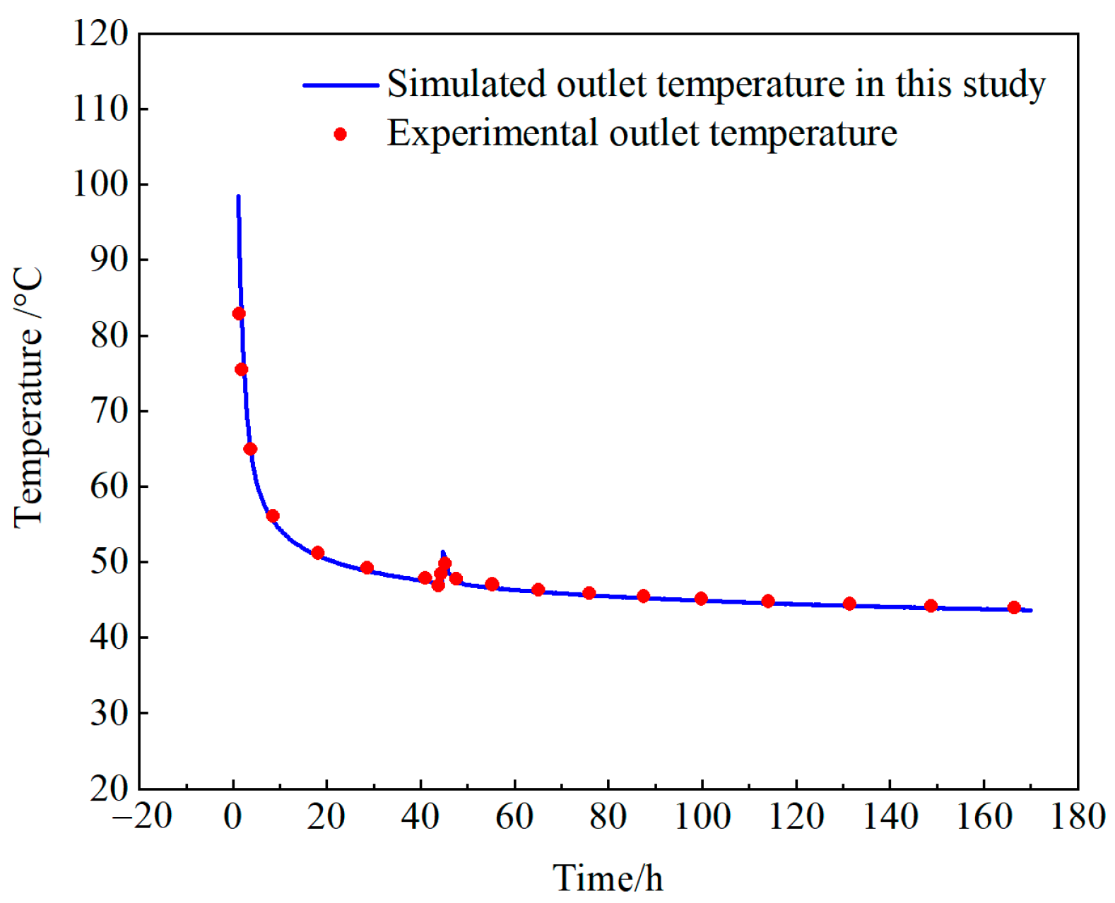
2.2.4. Model Validation

In Hawaii, a heat transfer field test of MBHE was carried out [41]. According to the measured parameters, the outlet temperatures were simulated by our model and compared with the test data (Figure 4). One power failure of 30 min occurred, which was also considered in our simulation. The simulated results were highly consistent with the field test data, with an average relative error of 0.48%, validating the accuracy of our model.

3. Results

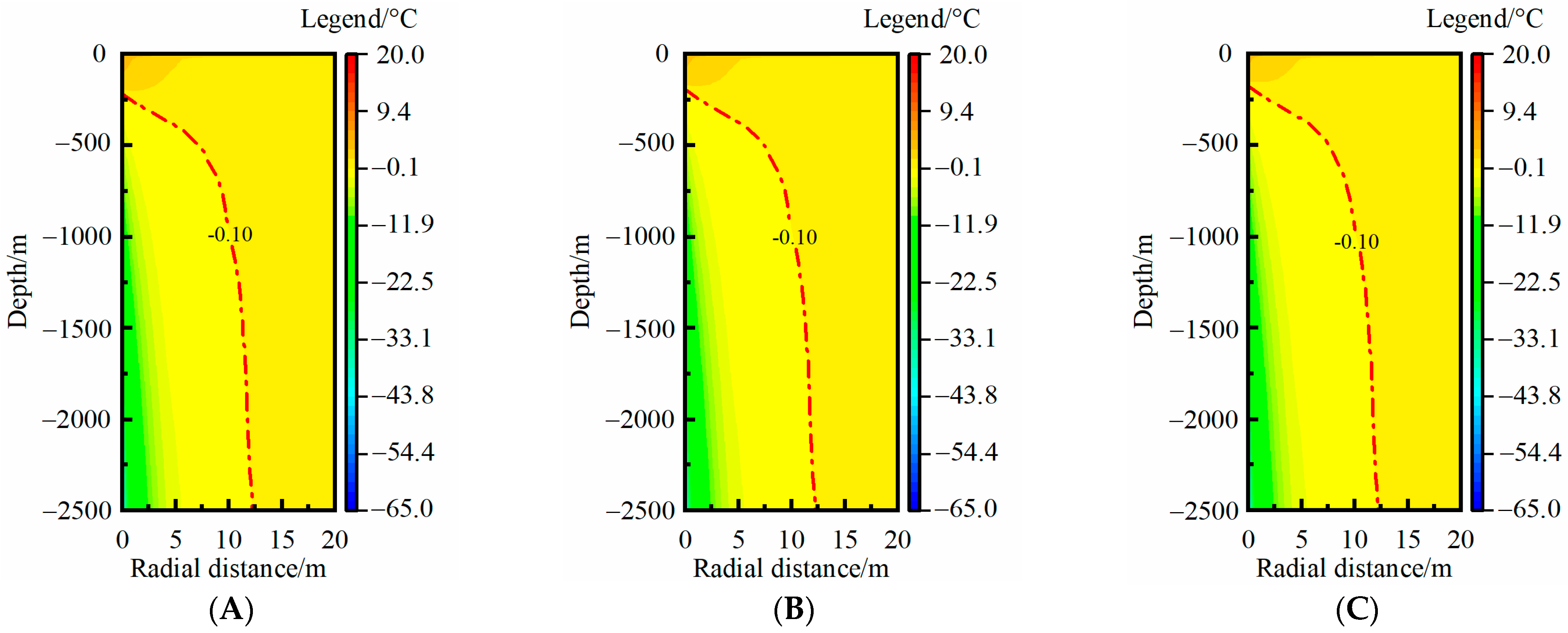
3.1. Rock-Soil Temperature Distribution in One Heating Season

Figure 5 shows the rock-soil temperature distribution in a heating season (4 months). The longitudinal coordinate axis represents the rock-soil depth below the ground surface and the horizontal axis represents the radial distance between the MBHE and rock soil. A smaller radial distance means that the rock soil was closer to the MBHE. To analyze the temperature distribution characteristics with the thermal extraction time of the MBHE, the calculated rock-soil temperatures at typical time nodes of 30, 60, 90, and 120 days were chosen. It can be seen that the rock-soil temperature largely decreased at a smaller radial distance. As the thermal extraction proceeded, the rock-soil temperature dropped in both the radial direction and vertical direction (Figure 5A). In general, the temperature change in the radial direction is paid more attention because of its practical significance for borehole spacing design. According to the change trend of the isotherm, the rock-soil temperature hardly changed beyond the radial distance of 6, 9, 11, and 12 m at 30, 60, 90, and 120 days. During a whole heating season, the TAR of the rock soil continuously increased. However, the extent of the increase gradually dropped because the temperature difference of the equidistant rock soil became smaller and smaller in the radial direction. At the end of the heating season, the TAR reached its maximum. Figure 5B shows the rock-soil temperature change compared with the undisturbed temperature. Three temperature drop isotherms of −0.5, −0.2, and −0.1 °C were chosen to analyze the RTAA. In comparison with Figure 5A,B reflects the RTAA more clearly. The larger temperature drop isotherm had a relatively smaller RTAA. According to the statistical analysis, the MTAR of the isotherm of −0.1 °C was 6.3, 9.0, 10.9, and 12.2 m, which was nearly consistent with the aforementioned results from Figure 5A. Thus, the isotherm of −0.1 °C was selected as an RTAA reference to analyze its characteristics in the following analysis.

3.2. Effects of Influencing Factors

The effects of the eight influencing factors (as shown in Table 1) were investigated. Because the RTAA continuously increases during a heating season, the rock-soil temperature distribution under various conditions at the end of heating season (120 days) in the first year was chosen for the analysis.

3.2.1. Thermal Extraction Load

Figure 6 shows the rock-soil temperature change under a thermal extraction load of 75, 100, and 125 W·m−1. Under the lower thermal extraction load, the rock-soil temperature change at a shallow depth was positive (Figure 6A), which meant heat transmission occurred from the MBHE to the rock soil. The length where the MBHE dissipated heat to the rock soil gradually decreased with an increase of the thermal extraction load. At a thermal extraction load of 75 W·m−1, about 500 m from the MBHE underwent heat dissipation. When the thermal extraction load increases to 125 W·m−1, the whole length of the MBHE extracted geothermal energy from the rock soil (Figure 6C). This was because the fluid temperature was lower under a higher thermal extraction load, and the fluid temperature of the MBHE was always lower than the rock-soil temperature at the same depth. In the radial direction, the maximum thermal affected radius (MTAR) increased by 0.38 m (from 12.00 to 12.38 m) when the thermal extraction load increased from 75 to 125 W·m−1, with an increase ratio of 3.2%. Variation in the thermal extraction load had an obvious effect on the RTAA in the vertical direction, but only slightly affected the MTAR.

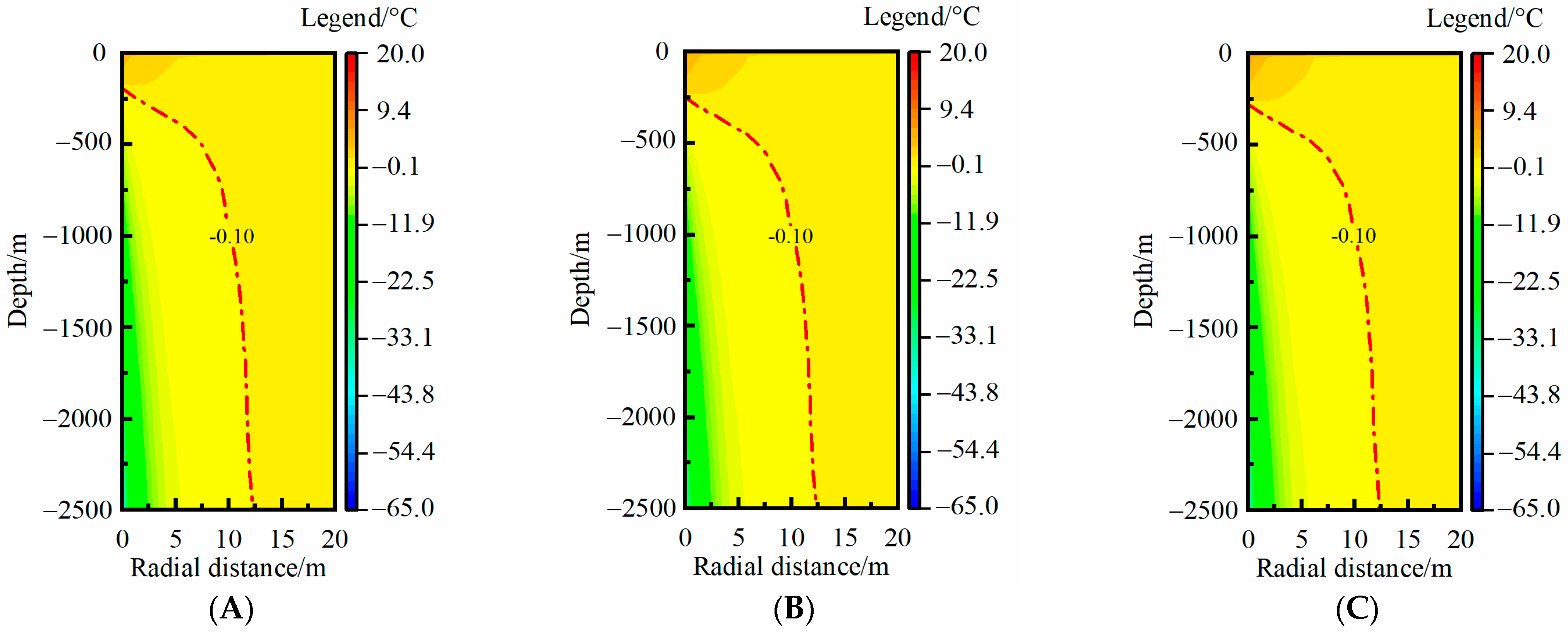
3.2.2. Geological Parameters

The quality of geothermal conditions can be indirectly evaluated by the geothermal flow, which is product of the rock-soil thermal conductivity and geothermal gradient. In this section, the effects of these two geological parameters on the rock-soil temperature distribution were analyzed.
Figure 7 shows the rock-soil temperature change at a rock-soil thermal conductivity of 2.0, 2.5, and 3.0 W·m−1·K−1. In the vertical direction, geothermal energy was extracted from the surrounding rock soil at nearly the whole depth under a lower thermal conductivity (Figure 7A). With an increase of thermal conductivity, the RTAA of the thermal extraction moved with the depth (Figure 7C). The MTAR increased by 0.89 m and 1.06 m, respectively, with an increase of 0.5 W·m−1·K−1 of thermal conductivity from 2.0 W·m−1·K−1 (Figure 7A) to 3.0 W·m−1·K−1 (Figure 7C). The MTAR increased by 17.2% when the thermal conductivity increased from 2.0 to 3.0 W·m−1·K−1, and the degree of increase further increased as the thermal conductivity increased. At a higher thermal conductivity, the thermal extraction effect of the MBHE further extended in the radial direction because the thermal resistance between the MBHE and rock soil was lower. The rock-soil thermal conductivity largely impacts the MTAR.
Figure 8 shows the rock-soil temperature change at a geothermal gradient of 25, 30, and 35 °C·km−1. As with the effect of rock-soil thermal conductivity, under lower geothermal gradient conditions, the geothermal energy was extracted from the surrounding rock soil for nearly the whole depth (Figure 8A). The RTAA of thermal extraction moved with the depth with an increase of the geothermal gradient. This was because the inlet temperature value of the MBHE was larger when the geothermal gradient was higher, resulting in an obvious temperature transfer from the MBHE to the rock soil at a shallower depth. The MTAR increased by only 0.26 m with increases of 5 °C·km−1 in the geothermal gradient from 25 °C·km−1 (Figure 8A) to 35 °C·km−1 (Figure 8C). The MTAR increased by 4.4% when the geothermal gradient increased from 25 to 35 °C·km−1, due to a negative effect from rock-soil thermal resistance, which indicated a variation in the geothermal gradient slightly impacted the MTAR of medium-deep rock soil.

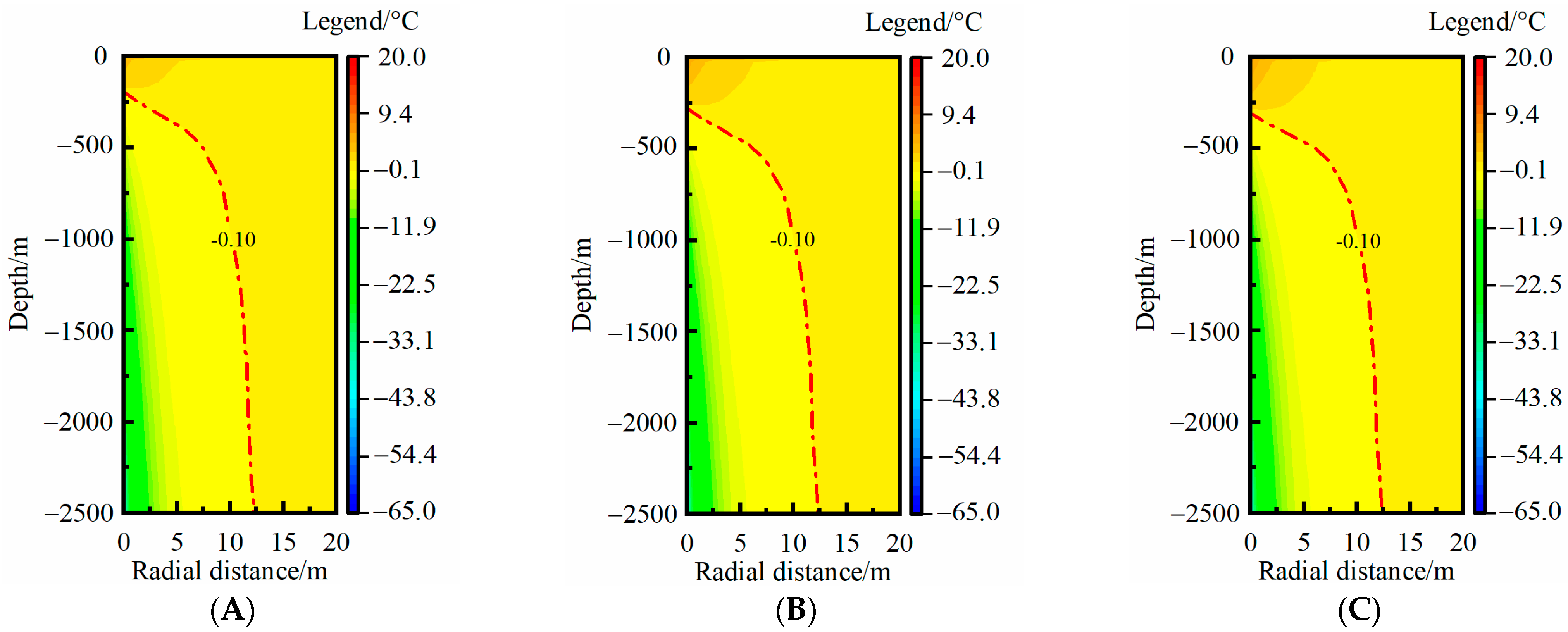
3.2.3. Operation Parameters

Fluid velocity is one of the most important operation parameters for thermal extraction of an MBHE. Elevating the fluid velocity contributes to improving the convective heat transfer coefficient between the MBHE and surrounding rock soil. Figure 9 shows the effects of fluid velocity on the rock-soil temperature change. It can be seen that the RTAA of thermal extraction mainly moved in the deeper direction as the fluid velocity increased, whereas the MTAR increased by only 0.1 and 0.1 m, respectively, with an increase of 0.1 m·s−1 of fluid velocity from 0.5 m·s−1 (Figure 9A) to 0.7 m·s−1 (Figure 9C). In general, a fluid velocity of 0.7 m·s−1 occurs at a relatively high level in the application of MBHEs because the thermal extraction capacity of the MBHEs cannot be effectively improved by continuously elevating the fluid velocity. Although an intensive heat transfer effect between the MBHE and rock soil could result in a large RTAA, the increase of MTAA in the radial direction would be limited due to a higher thermal resistance between the MBHE and rock soil at a greater distance. Based on the above analysis, it can be concluded that the fluid velocity hardly affects the MTAR.

3.2.4. Design Parameters

The design parameters of MBHEs mainly involve the pipe length and diameter. MBHEs with a longer pipe length have a better thermal extraction capacity. Figure 10 shows the surrounding rock-soil temperature change of MBHEs with different pipe lengths. The RTAA was affected by different pipe lengths in the vertical direction. The RTAA of thermal extraction moved with increasing depth as the pipe length increased (Figure 10A–C). This is because an MBHE with a longer pipe length usually has a higher fluid temperature, which is even higher than that of the rock soil at a shallow depth. As the depth increases, the fluid temperature gradually becomes lower than the rock soil. In the radial direction, due to the effect of thermal resistance between the MBHE and rock soil, the MTAR increased by only 0.20 m with an increase of 500 m of pipe length from 2000 m (Figure 10A) to 3000 m (Figure 10C). The MTAR increased by 3.6% when the pipe length increased from 2000 to 3000 m, which indicates pipe length slightly impacts the MTAR of medium-deep rock soil, i.e., MBHEs under the same geological conditions have a basically constant MTAR.
Additionally, the effects of inner pipe diameter (Figure A1), outer pipe diameter (Figure A2), and inner pipe thermal conductivity (Figure A3) on the rock-soil temperature change were analyzed. We found that variation in these three factors mainly affected the RTAA in the vertical direction. For an MBHE with a smaller inner pipe diameter, larger outer pipe diameter, and/or lower inner pipe thermal conductivity, the RTAA of thermal extraction was positioned at a deeper depth. However, the MTAR hardly varied with pipe diameter and inner pipe thermal conductivity.

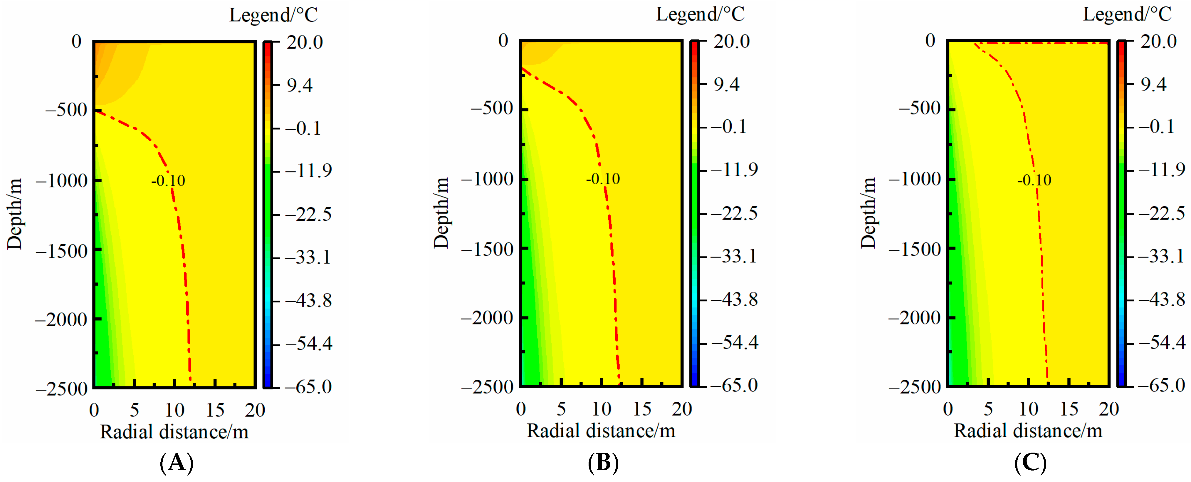
3.3. Rock-Soil Temperature Distribution in the Full Lifecycle

3.3.1. Rock-Soil TAR

In the full lifecycle, MBHE extracts the geothermal energy in the heating season and stops running in the non-heating season. According to the study described in Section 3.1, the TAR of medium-deep rock soil reaches the maximum value at the end of the heating season. During the non-heating season, the rock-soil temperature begins to recover under the effect of geothermal flow, which has a non-negligible impact on the TAR. In order to assess the MTAR over a full lifecycle, the rock-soil temperature distribution change during the duration of a 30-year thermal extraction was analyzed. In every year, a period of 4 months was set as the heating season and the rest of the year was set as the non-heating season, which was determined by the building heating time in northern China.
Figure 11 shows the TAR of medium-deep rock soil at the end of the heating season and non-heating season in different years. In the first year, the decline degree of the rock-soil temperature closer to the MBHE was larger, with a maximum value of 50 °C, and the MTAR was 12.2 m at the end of the heating season. During the non-heating season, the rock-soil temperature surrounding the MBHE recovered significantly but did not reach the undisturbed condition. The maximum temperature drop increased to 2.8 °C. The MTAR continued to increase during the non-heating season and expanded to 20.0 m at the end of the non-heating season, which was nearly equal to twice the MTAR at the end of the heating season (Figure 11A). It can be concluded that the temperature difference of medium-deep rock soil in the radial direction dominates the temperature recovery of rock soil surrounding the MBHE in the first year. As the thermal extraction proceeded, the MTAR continuously increased to 51.4, 72.5, and 89.9 m at the end of the non-heating season in the 10th, 20th, and 30th year (Figure 11B–D), respectively. The increase degree of the MTAR with thermal extraction time gradually declined. Comparing the TAR at the end of the heating season and non-heating season, their difference gradually reduced. After 20 years of thermal extraction, the TAR at the end of the heating season and non-heating season tended to be consistent (Figure 11C), which indicates that the geothermal flow dominates the temperature recovery. In the 30th year, the TAR at the end of the heating season and non-heating season basically coincided (Figure 11D).
While the MTAR may still continue to extend after 30 years of thermal extraction, a balance has basically been reached between the thermal extraction of the MBHE and the thermal recovery of the medium-deep rock soil at the 30th year. The thermal extraction capacity of the MBHE remains almost constant and settles into a quasi-steady state, which was validated in our previous study [40]. The MTAR in the 30th year could be considered as an effective MTAR of the full lifecycle, which has reference value for borehole spacing design to ensure the sustainable thermal extraction of a single MBHE.

3.3.2. Main Influencing Factors Analysis

According to the analysis in Section 3.2, the rock-soil thermal conductivity has an obvious effect on TAR. The thermal extraction loads of an MBHE usually have a large fluctuation range in different engineering projects. Thus, the effects of the two mentioned factors on the MTAR over the full lifecycle were investigated. The maximum radius of the full lifecycle was compared with the MTAR in the first year to analyze the variation of the TAR during the full lifecycle (Figure 12).
Figure 12A shows the effects of the thermal extraction load. Compared with the MTAR in the first year, the maximum radius over the full lifecycle was significantly larger, at over 80 m. However, the maximum radius only enlarged by nearly 5.0 m when the thermal extraction load increased from 50 W·m−1 to 125 W·m−1, indicating a slight effect on the variations in the maximum radius. Figure 12B shows the effects of rock-soil thermal conductivity. In the first year, the MTAR at 3.0 W·m−1·K−1 was 5.0 m larger than that at 1.5 W·m−1·K−1. During the full lifecycle, the difference of maximum radius between the conditions of 3.0 W·m−1·K−1 and 1.5 W·m−1·K−1 increased to 22.3 m. The MTAR at 3.0 W·m−1·K−1 reached 96 m. With higher rock-soil thermal conductivity, the increase degree of MTAR with thermal extraction year was more obvious, and the thermal interference between adjacent MBHEs should be paid attention.

3.4. New Layout Form

3.4.1. Layout Form Proposal

During the full lifecycle, the TAR significantly increases with the thermal extraction year. The maximum radius over the full lifecycle, as analyzed in Section 3.3.2, reaches over 70 m, which means a spacing of more than 140 m between adjacent MBHEs should be utilized. This is difficult to implement for heating applications using multiple MBHE arrays because of limitations in the project site area. Thus, optimizing the layout form is necessary.
Based on the above analysis of the rock-soil temperature distribution characteristics, the main RTAA was focused on the deep part of the rock soil and the MTAR in the full lifecycle was positioned nearly at the depth of the pipe bottom, whereas the MTAR at a shallow depth (<200 m) was limited to 20 m. A new layout form for an inclining borehole was proposed in this study (Figure 13), the aim of which was to reduce ground surface occupation and avoid thermal interference between adjacent MBHEs as much as possible.
By inclining the adjacent MBHEs in opposite directions, the overlapping RTAA decreased, even if the wellhead between adjacent MBHEs was close. The specific position relationship is shown in Figure 14.
The normal MBHE was vertically installed and the new layout form was obliquely installed. There was an angle (θ) formed between the normal form and the new form. One benchmark angle was proposed, as follows:
θ = arcsin ( R max H )
where θ, Rmax, and H are the TAR angle, MTAR in the full lifecycle, and pipe length, respectively. Because the horizontal offset of the MBHE bottom was determined based on the MTAR in the full lifecycle, the formed angle (θ) was named the TAR angle in this work.

3.4.2. Thermal Affected Area Analysis

The MTAR in the full lifecycle is significantly affected by the rock-soil thermal conductivity, but is hardly affected by the thermal extraction load, fluid velocity, and design parameters. It can be concluded that the horizontal offset of MBHE after inclining it will only result in a position shift of the RTAA, rather than a variation in the MTAR.
According to the optimal design method of thermal extraction capacity in our previous study [40], the recommended thermal extraction load and optimal operating parameters in the benchmark condition (shown in Table 1) could be determined. Then, the MTAR in the full lifecycle, obtained by the rock-soil temperature distribution analysis, was 91.3 m. Consequently, the TAR angle calculated by Equation (11) was 2.1°. Figure 15 shows the effects of the TAR angle of different multiples on the MTAR in the full lifecycle. The position of the MBHE before inclining was x = 0 m. The black solid line represents the TAR of different depths for an MBHE without inclining. In order to avoid thermal interference to the right of the line x = 0 m, the MBHE would be inclined in the opposite x direction. It is noteworthy that after the incline of one TAR angle, the thermal interference could only be avoided at the depth of the MBHE bottom. A large amount of RTAA still existed to the right of line x = 0 m and may result in thermal interference if the adjacent spacing is less than the MTAR. Thus, the incline angle needed to be further enlarged. When the incline angle was increases to four times the TAR angle, about 80% of the whole depth fully avoided thermal interference, whilst the RTAA could not be efficiently reduced to the right of line x = 0 m at four times the TAR angle. Therefore, four times the TAR angle was determined as the optimal incline angle. Due to the incline, the vertical depth of an MBHE with four times the TAR angle decreased by 26.6 m compared with the initial vertical depth of 2500 m, whereas the decreased depth hardly affected the thermal extraction of the MBHE, according to a previous study [40].
Furthermore, the optimal incline angle of the MBHE under different rock-soil thermal conductivities was analyzed. The results showed that four times the TAR angle could still avoid the thermal interference of adjacent MBHEs for over 80% of the whole depth. Moreover, the thermal interference degree at a shallow depth was smaller than that at a greater depth [18], and the thermal extraction area of the MBHE was mainly positioned more deeply [33]. Four times the TAR angle can be recommended as the optimal design inflection angle. The optimal TAR angles of MBHEs and corresponding vertical depths under various rock-soil thermal conductivities of 2.0–3.0 W·m−1·K−1 are given in Table 3. The MBHE length ranged from 2000 to 3000 m. As the pipe length increased, the optimal TAR angle became smaller. Additionally, as the vertical depth of the MBHE after inclining declined, the decline degree hardly impacted the thermal extraction of the MBHE.
The new layout significantly reduced the borehole spacing between the adjacent MBHEs. According to the results in Figure 12, the installed distance on the ground surface between the two vertical MDBHEs reached over 140 m (at 1.5 W·m−1·K−1). After using the new layout in our study, the installed distance on the ground surface could be reduced to less than 5 m, reserving the positioning of the pipeline connection and monitoring equipment, which decreased the construction difficulty. Simultaneously, with the same usable ground area, more MBHEs could be utilized by using the new layout. The medium-deep geothermal energy could thus be effectively exploited and utilized.
With the new layout form, the spacing distance between the wellhead positions of adjacent MBHEs could be significantly reduced, which would greatly contribute to reducing the ground surface occupation.

4. Discussion

In previous studies, MBHEs were usually analyzed in a vertical installed form. The MTAR is a key indicator for the design of borehole spacing to avoid thermal interference. The authors of [36] suggested a borehole spacing of 50–60 m, but the referred rock-soil thermal conductivity was less than 2.0 W·m−1·K−1 and the specific heat load was less than 100 W·m−1. Rock-soil thermal conductivity in a medium-deep geothermal reservoir may reach over 2.5 W·m−1·K−1 [26,31], or even as much as 3.5 W·m−1·K−1 [30], and the specific heat load is usually over 100 W·m−1. To improve its thermal extraction efficiency, a borehole spacing of 50–60 m is insufficient for the conditions of higher rock-soil thermal conductivity and a larger heating load. A larger borehole spacing has to be used, which may be limited by the usable ground area in practical engineering. From the analysis in Section 3, we found that the TAR at a shallow depth was significantly smaller than at greater depths. The factors of the thermal extraction load, fluid velocity, geothermal gradient, and pipe length impact on the RTAA in the vertical direction. The rock-soil thermal conductivity affects the RTAA in both the radial and vertical directions. The distribution characteristics of the RTAA were clarified. Because the RTAA mainly exists at greater depths, the thermal interference could be effectively avoided if the borehole spacing was large enough for these depths. Instead of using vertical forms, the inclined form is more rational. Through simulations, four times the TAR angle was determined as the optimal incline angle, the design of which would not impact the thermal performance of every MBHE. The effect of groundwater flow was not considered in this study, mainly because MBHEs are usually applied in geological conditions with poor hydrothermal resources. A hydrothermal geothermal heating technique is preferred in geological conditions with effective groundwater velocity. However, groundwater could result in different variations in the RTAA. In a future study, the groundwater flow will be considered in our model, and its characteristics, including the groundwater velocity, groundwater position, and groundwater direction, will be further analyzed in terms of their effect on the RTAA.

5. Conclusions

In this work, the medium-deep rock-soil temperature characteristics under different time scales were investigated. Using a single heating season analysis, the TAR distribution of medium-deep rock soil at different depths was obtained so that the MTAR could be determined. Then, the rounded parametric analysis, including the effects of the thermal extraction load, geological parameters, operating parameters, and design parameters on the MTAR, was carried out to demonstrate the evolution of the MTAR. Next, considering the MBHE operation feature of extracting geothermal energy in the heating season and stopping geothermal extraction in the non-heating season, the evolution mechanism of the medium-deep rock-soil temperature over the full lifecycle was clarified, and the effective MTAR was discovered. Finally, based on the above analysis, a new layout form for the MBHEs was proposed, the advantage of which was effectively reducing ground surface occupation and simultaneously avoiding thermal interference between adjacent MBHEs.
The results showed that the rock-soil thermal affected area (RTAA) continuously expanded in both the radial and vertical directions during a heating season. The factors of the thermal extraction load, fluid velocity, geothermal gradient, and pipe parameters impacted on the RTAA in the vertical direction. The rock-soil thermal conductivity affected the RTAA in both the radial and vertical directions. In the non-heating season, the temperature difference of the medium-deep rock soil in the radial direction dominated the temperature recovery of the rock soil surrounding the MBHE in the first year, but after 20 years of thermal extraction, the geothermal flow dominated the temperature recovery. The RTAA rapidly expanded in the initial years. The thermal affected radius (TAR) in the 30th year could be determined as an effective MTAR for the full lifecycle. In order to decrease the installed distance of adjacent MBHEs on the surface, a new layout form with inclined boreholes was proposed. When the incline angle was equal to or larger than four times the TAR angle, thermal interference between the adjacent MBHEs could be effectively avoided. This work provides a theoretical foundation and scientific reference for promoting the application of multiple MBHE arrays.
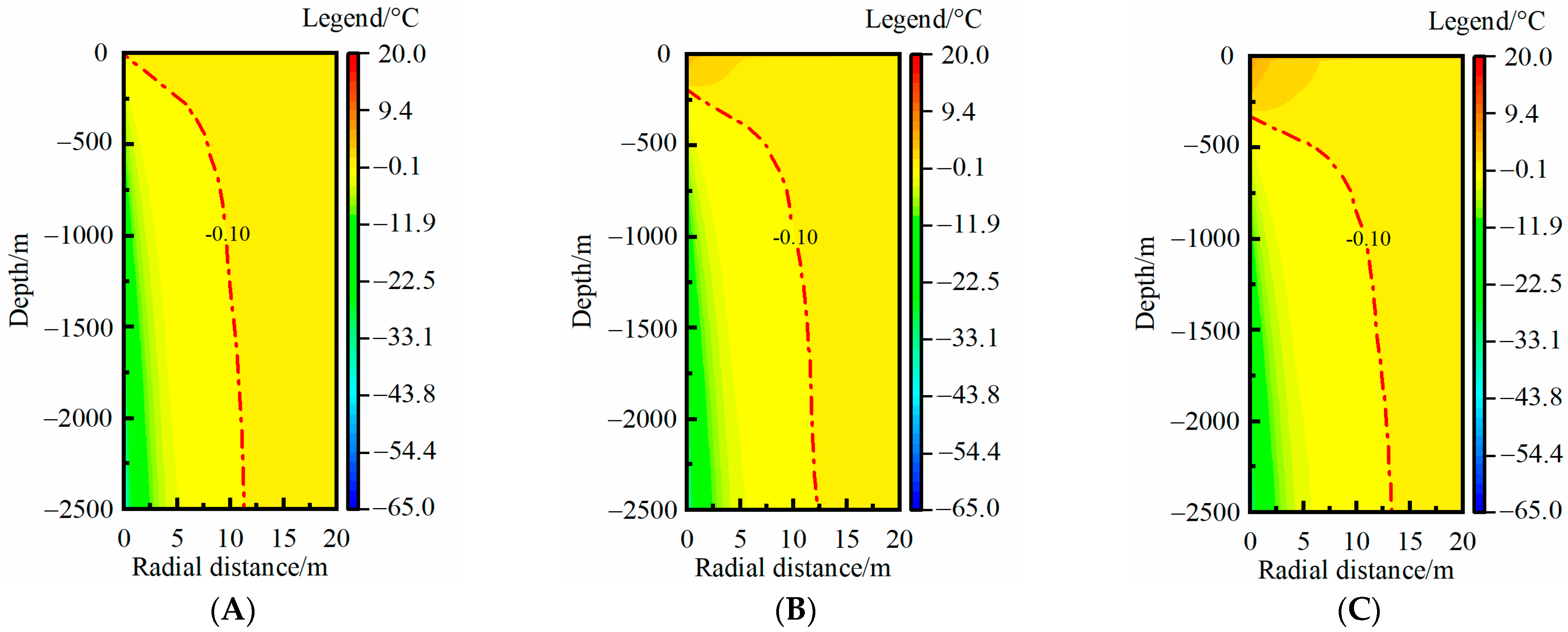
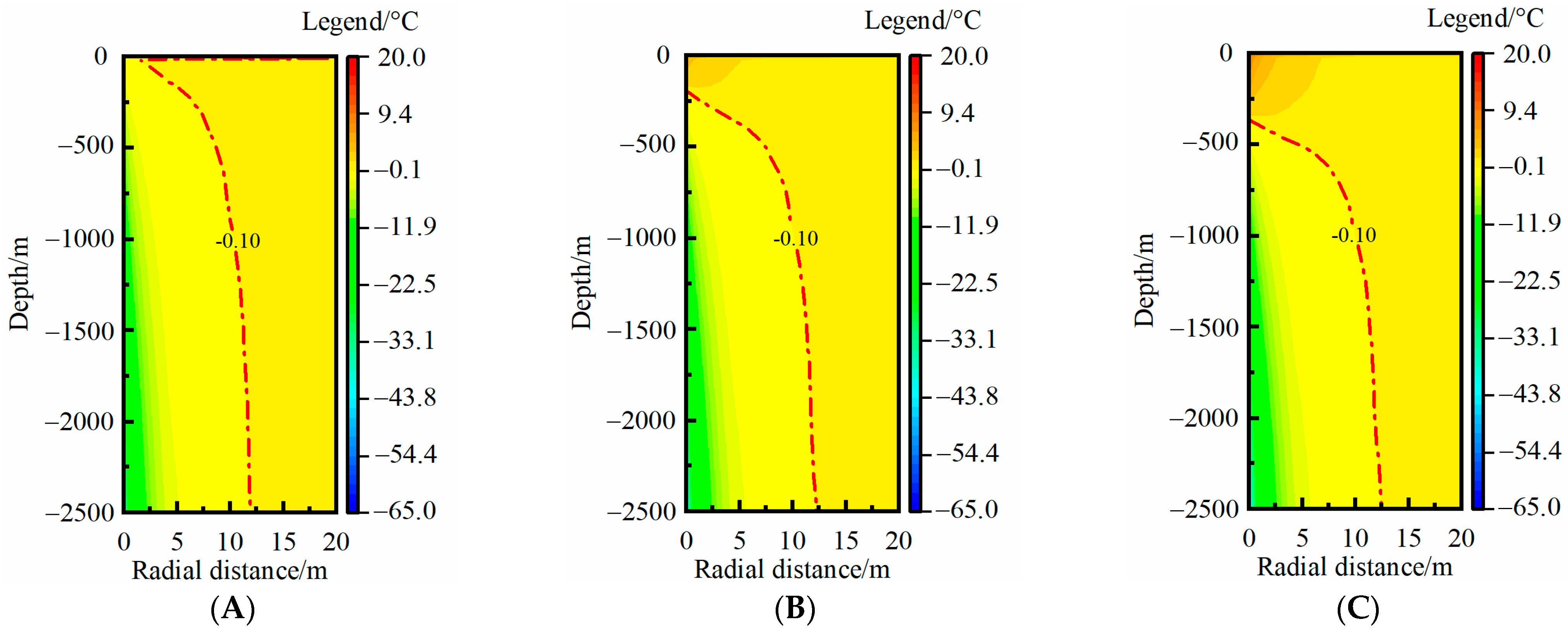
  • The RTAA continuously expanded in both the radial and vertical directions during a heating season. Among the analyzed influencing factors, only the rock-soil thermal conductivity significantly affected the RTAA in both the radial and vertical directions. The MTAR increased by 17.2% when the thermal conductivity increased from 2.0 to 3.0 W·m−1·K−1, and the increase degree further increased as the thermal conductivity increased. Other factors had impacts on the RTAA only in the vertical direction.
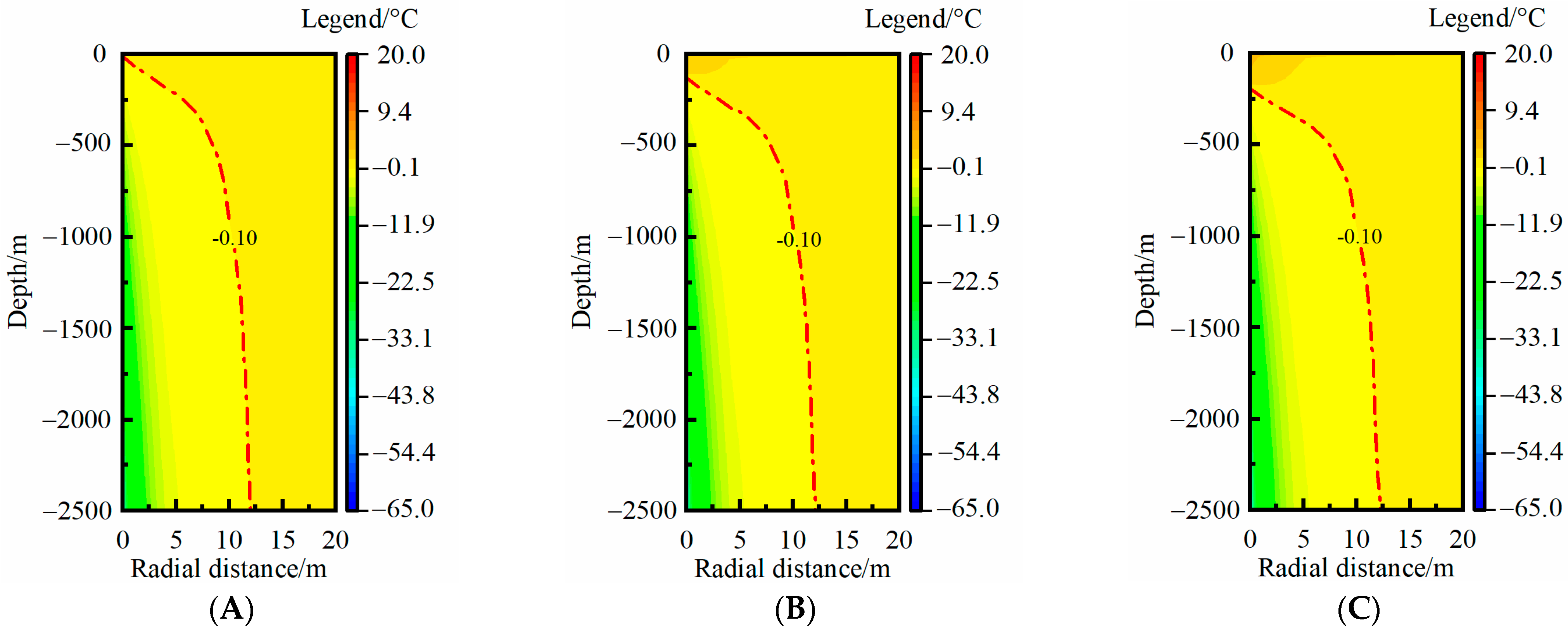
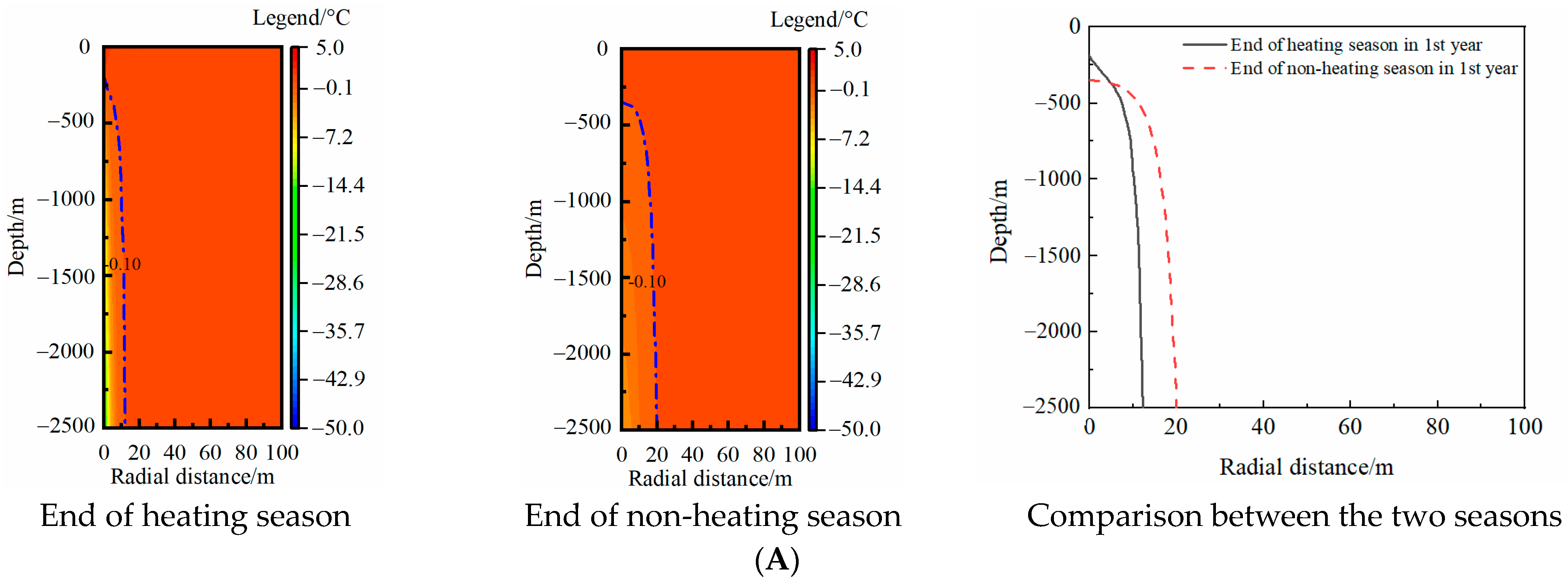
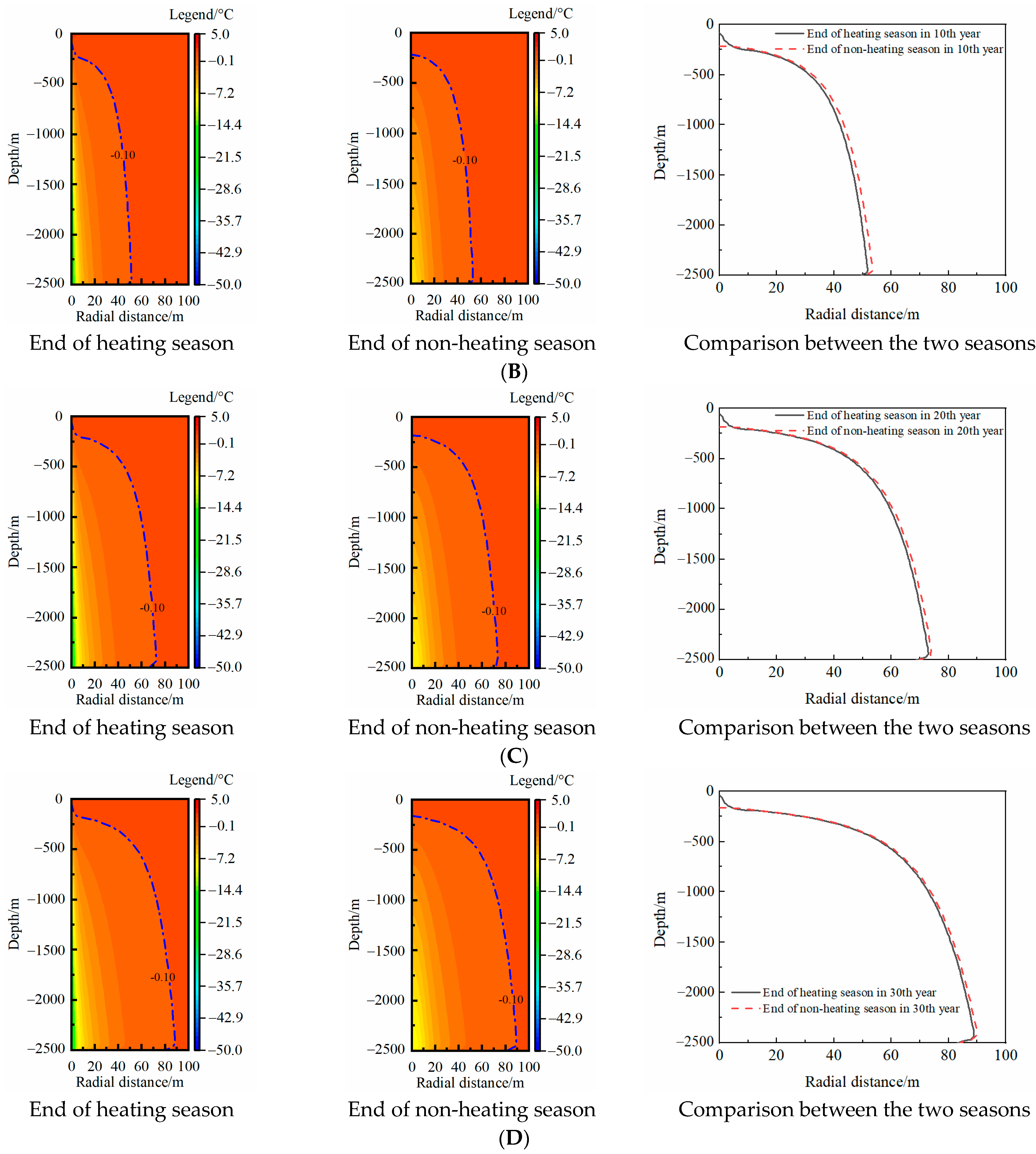
  • The temperature recovery mechanism in the non-heating season of medium-deep rock soil varied with the thermal extraction year. In the first year, the temperature difference of the medium-deep rock soil in the radial direction dominated the temperature recovery of the rock soil, whereas the geothermal flow dominated the temperature recovery after 20 years of thermal extraction. In the 30th year, the TAR at the end of the heating season and non-heating season basically coincided.
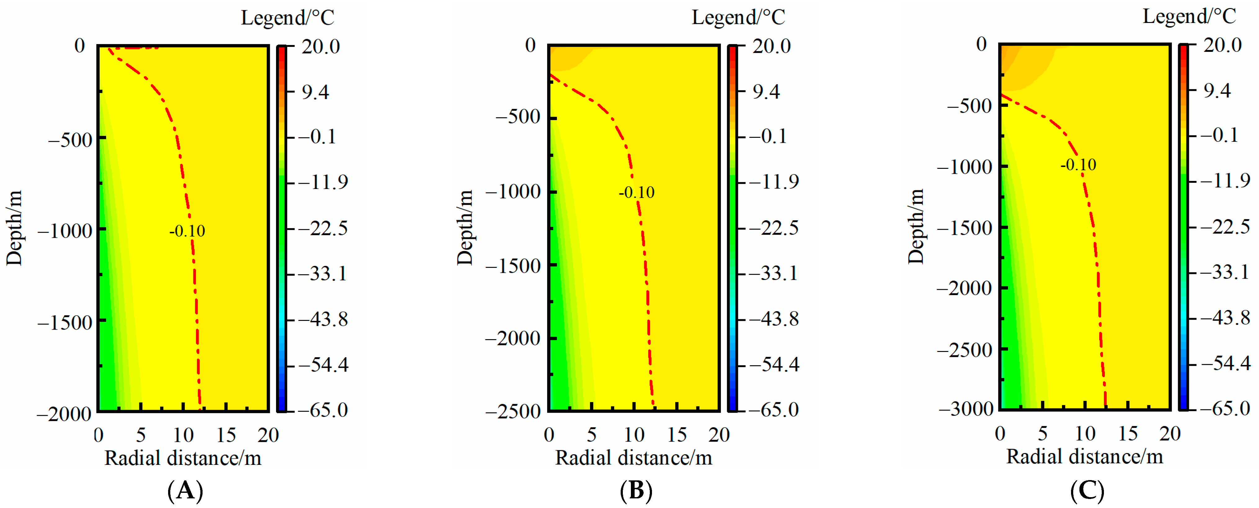
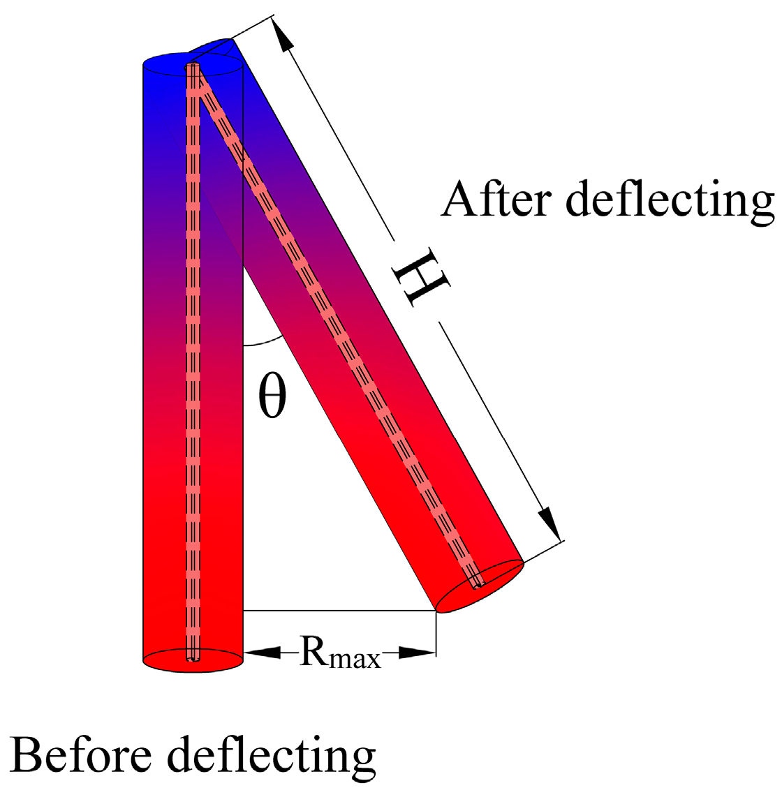
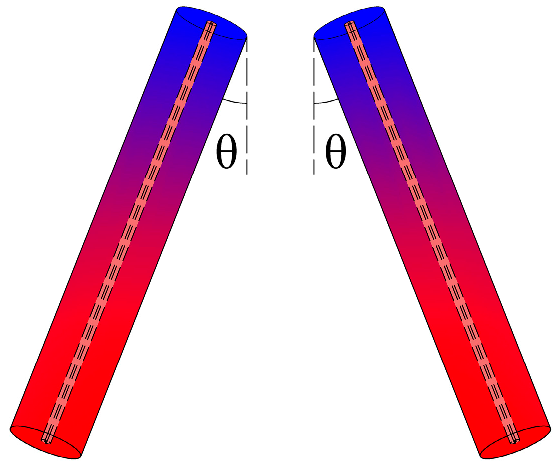
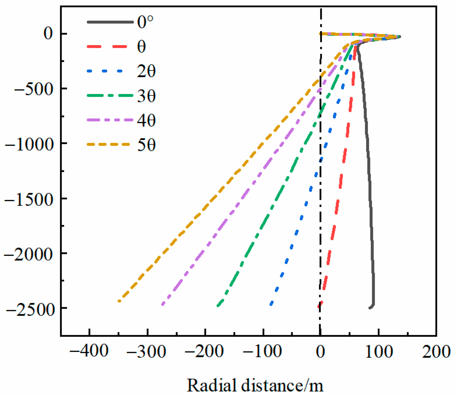
  • The TAR in the 30th year represented the effective MTAR over the full lifecycle. According to the rock-soil temperature distribution characteristics, the main RTAA was focused on the deep part of the rock soil, and the MTAR over the full lifecycle was positioned nearly at the depth of the pipe bottom, so a new layout form with inclining boreholes was proposed. Four times the TAR angle was recommended as optimal incline angle, which could effectively avoid thermal interference between the adjacent MBHEs.

Author Contributions

Conceptualization, J.L. and F.W.; methodology, J.L. and Z.W.; software, Z.W.; validation, Y.Z., C.Z. and B.L.; formal analysis, Z.W.; investigation, B.L.; resources, Y.Z.; data curation, Z.W.; writing—original draft preparation, J.L.; writing—review and editing, F.W.; visualization, F.W.; supervision, F.W.; project administration, Y.Z., C.Z. and B.L.; and funding acquisition, Y.Z. All authors have read and agreed to the published version of the manuscript.

Funding

This research was funded by Young Talent Fund of Shaanxi Association for Science and Technology (NYHB202218), Shaanxi Province Qin Chuangyuan “Scientist + Engineer” Team Construction (2022KXY-039), Shaanxi Province State-owned Assets Special Fund Project for Technological Innovation in Business Budget (2022-10).

Data Availability Statement

The data presented in this study are available on request from the corresponding author.

Conflicts of Interest

The authors declare no conflict of interest.

Appendix A

Figure A1. Effects of inner pipe diameter on rock-soil temperature change at the end of the heating season in the first year compared with the undisturbed condition: (A) r = 0.045 m, (B) r = 0.055 m, and (C) r = 0.0625 m.
Energies 16 06970 g0a1
Figure A2. Effects of outer pipe diameter on rock-soil temperature change at the end of the heating season in the first year compared with the undisturbed condition: (A) R = 0.0889 m, (B) R = 0.1096 m, and (C) R = 0.1223 m.
Energies 16 06970 g0a2
Figure A3. Effects of inner pipe thermal conductivity on rock-soil temperature change at the end of the heating season in the first year compared with the undisturbed condition: (A) 0.45 W·m−1·K−1, (B) 0.20 W·m−1·K−1, and (C) 0 W·m−1·K−1.
Energies 16 06970 g0a3

References

  1. Wang, F.; Harindintwali, J.D.; Yuan, Z.Z.; Wang, M.; Wang, F.M.; Li, S.; Yin, Z.G.; Huang, L.; Fu, Y.H.; Li, L.; et al. Technologies and perspectives for achieving carbon neutrality. Innovation 2021, 2, 100180. [Google Scholar] [CrossRef] [PubMed]
  2. Li, Q.; Wang, F.L.; Wang, Y.L.; Forson, K.; Cao, L.L.; Zhang, C.L.; Zhou, C.; Zhao, B.; Chen, J.S. Experimental investigation on the high-pressure sand suspension and adsorption capacity of guar gum fracturing fluid in low-permeability shale reservoirs: Factor analysis and mechanism disclosure. Environ. Sci. Pollut. Res. 2022, 29, 53050–53062. [Google Scholar] [CrossRef]
  3. Wang, F.L.; Xiao, Z.X.; Liu, X.; Ren, J.W.; Xing, T.; Li, Z.; Li, X.Y.; Chen, Y.L. Strategic design of cellulose nanofibers@zeolitic imidazolate frameworks derived mesoporous carbon-supported nanoscale CoFe2O4/CoFe hybrid composition as trifunctional electrocatalyst for Zn-air battery and self-powered overall water-splitting. J. Power Sources 2022, 521, 230925. [Google Scholar] [CrossRef]
  4. Li, Q.C.; Han, Y.; Liu, X.; Ansari, U.; Cheng, Y.F.; Yan, C.L. Hydrate as a by-product in CO2 leakage during the long-term sub-seabed sequestration and its role in preventing further leakage. Environ. Sci. Pollut. Res. 2022, 29, 77737–77754. [Google Scholar] [CrossRef]
  5. Chahartaghi, M.; Kalami, M.; Ahmadi, M.H.; Kumar, R.; Jilte, R. Energy and exergy analyses and thermo-economic optimization of geothermal heat pump for domestic water heating. Int. J. Low-Carbon Technol. 2019, 14, 108–121. [Google Scholar] [CrossRef]
  6. Ghazvini, M.; Sadeghzadeh, M.; Ahmadi, M.H.; Moosavi, S.; Pourfayaz, F. Geothermal energy use in hydrogen production: A review. Int. J. Energy Res. 2019, 43, 7823–7851. [Google Scholar] [CrossRef]
  7. Lund, J.W.; Toth, A.N. Direct utilization of geothermal energy 2020 worldwide review. Geothermics 2020, 90, 101915. [Google Scholar] [CrossRef]
  8. Tang, F.J.; Nowamooz, H. Long-term performance of a shallow borehole heat exchanger installed in a geothermal field of Alsace region. Renew. Energy 2018, 128, 210–222. [Google Scholar] [CrossRef]
  9. Zhang, W.K.; Li, W.J.; Sørensen, B.R.; Cui, P.; Man, Y.; Yu, M.Z.; Fang, Z.H. Comparative analysis of heat transfer performance of coaxial pipe and U-type deep borehole heat exchangers. Geothermics 2021, 96, 102220. [Google Scholar] [CrossRef]
  10. Chen, S.; Cai, W.L.; Witte, F.; Wang, X.R.; Wang, F.H.; Kolditz, O.; Shao, H.B. Long-term thermal imbalance in large borehole heat exchangers array—A numerical study based on the Leicester project. Energy Build. 2021, 231, 110518. [Google Scholar] [CrossRef]
  11. Kohl, T.; Brenni, R.; Eugster, W. System performance of a deep borehole heat exchanger. Geothermics 2002, 31, 687–708. [Google Scholar] [CrossRef]
  12. Śliwa, T.; Kotyza, J. Application of existing wells as ground heat source for heat pumps in Poland. Appl. Energy 2003, 74, 3–8. [Google Scholar] [CrossRef]
  13. Huchtemann, K.; Müller, D. Combined simulation of a deep ground source heat exchanger and an office building. Build. Environ. 2014, 73, 97–105. [Google Scholar] [CrossRef]
  14. Kelkar, S.; Wolde, G.G.; Rehfeldt, K. Lessons learned from the pioneering hot dry rock project at Fenton Hill, USA. Geothermics 2016, 63, 5–14. [Google Scholar] [CrossRef]
  15. Ghavidel, A.; Gracie, R.; Dusseault, M.B. Design parameters impacting electricity generation from horizontal multilateral closed-loop geothermal systems in hot dry rock. Geothermics 2022, 105, 102469. [Google Scholar] [CrossRef]
  16. Liu, D.X.; Zhang, W.; Lu, X.L.; Zhang, J.Q.; Meng, Q.Y.; Hu, M.Q.; Liu, J.L. Research on a novel type of hot dry rock power generation system coupled with Kalina and ORC. Energy Rep. 2022, 8, 65–76. [Google Scholar] [CrossRef]
  17. Li, J.; Xu, W.; Li, J.F.; Huang, S.; Li, Z.; Qiao, B.; Yang, C.; Sun, D.Y.; Zhang, G.Q. Heat extraction model and characteristics of coaxial deep borehole heat exchanger. Renew. Energy 2021, 169, 738–751. [Google Scholar] [CrossRef]
  18. Cai, W.L.; Wang, F.H.; Chen, S.; Chen, C.F.; Liu, J.; Deng, J.W.; Kolditz, O.; Shao, H.B. Analysis of heat extraction performance and long-term sustainability for multiple deep borehole heat exchanger array: A project-based study. Appl. Energy 2021, 289, 116590. [Google Scholar] [CrossRef]
  19. Wang, Z.H.; Wang, F.H.; Liu, J.; Ma, Z.J.; Han, E.S.; Song, M.J. Field test and numerical investigation on the heat transfer characteristics and optimal design of the heat exchangers of a deep borehole ground source heat pump system. Energy Convers. Manag. 2017, 153, 603–615. [Google Scholar] [CrossRef]
  20. Deng, J.W.; Wei, Q.P.; Liang, M.; He, S.; Zhang, H. Field test on energy performance of medium-depth geothermal heat pump systems (MD-GHPs). Energy Build. 2019, 184, 289–299. [Google Scholar] [CrossRef]
  21. Deng, J.W.; He, S.; Wei, Q.P.; Li, J.F.; Liu, H.; Zhang, Z.P.; Zhang, H. Field test and optimization of heat pumps and water distribution systems in medium-depth geothermal heat pump systems. Energy Build. 2020, 209, 109724. [Google Scholar] [CrossRef]
  22. Welsch, B.; Rühaak, W.; Schulte, D.O.; Bär, K.; Sass, I. Characteristics of medium deep borehole thermal energy storage. Int. J. Energy Res. 2016, 40, 1855–1868. [Google Scholar] [CrossRef]
  23. Hu, X.C.; Banks, J.; Wu, L.P.; Liu, W.V. Numerical modeling of a coaxial borehole heat exchanger to exploit geothermal energy from abandoned petroleum wells in Hinton, Alberta. Renew. Energy 2020, 148, 1110–1123. [Google Scholar] [CrossRef]
  24. Bu, X.B.; Ma, W.B.; Li, H.S. Geothermal energy production utilizing abandoned oil and gas wells. Renew. Energy 2012, 41, 80–85. [Google Scholar] [CrossRef]
  25. He, Y.J.; Bu, X.B. A novel enhanced deep borehole heat exchanger for building heating. Appl. Therm. Eng. 2020, 178, 115643. [Google Scholar] [CrossRef]
  26. Song, X.Z.; Wang, G.S.; Shi, Y.; Li, R.X.; Xu, Z.M.; Zheng, R.; Wang, Y.; Li, J.C. Numerical analysis of heat extraction performance of a deep coaxial borehole heat exchanger geothermal system. Energy 2018, 164, 1298–1310. [Google Scholar] [CrossRef]
  27. Fang, L.; Diao, N.R.; Shao, Z.K.; Zhu, K.; Fang, Z.K. A computationally efficient numerical model for heat transfer simulation of deep borehole heat exchangers. Energy Build. 2018, 167, 79–88. [Google Scholar] [CrossRef]
  28. Chen, C.F.; Shao, H.B.; Naumov, D.; Kong, Y.L.; Tu, K.; Kolditz, O. Numerical investigation on the performance, sustainability, and efficiency of the deep borehole heat exchanger System for Building Heating. Geotherm. Energy 2019, 7, 18. [Google Scholar] [CrossRef]
  29. Le Lous, M.; Larroque, F.; Dupuy, A.; Moignard, A. Thermal performance of a deep borehole heat exchanger: Insights from a synthetic coupled heat and flow model. Geothermics 2015, 57, 157–172. [Google Scholar] [CrossRef]
  30. Holmberg, H.; Acuna, J.; Næss, E.; Sønju, O. Thermal evaluation of coaxial deep borehole heat exchangers. Renew. Energy 2016, 97, 65–76. [Google Scholar] [CrossRef]
  31. Liu, J.; Wang, F.H.; Cai, W.L.; Wang, Z.H.; Li, C. Numerical investigation on the effects of geological parameters and layered subsurface on the thermal performance of medium-deep borehole heat exchanger. Renew. Energy 2020, 149, 384–399. [Google Scholar] [CrossRef]
  32. Wang, Z.Y.; Wang, F.H.; Liu, J.; Li, Y.Z.; Wang, M.; Luo, Y.Q.; Ma, L.X.; Zhu, C.; Cai, W.L. Energy analysis and performance assessment of a hybrid deep borehole heat exchanger heating system with direct heating and coupled heat pump approaches. Energy Convers. Manag. 2023, 276, 116484. [Google Scholar] [CrossRef]
  33. Liu, J.; Wang, F.H.; Cai, W.L.; Wang, Z.H.; Wei, Q.P.; Deng, J.W. Numerical study on the effects of design parameters on the heat transfer performance of coaxial deep borehole heat exchanger. Int. J. Energy Res. 2019, 43, 6337–6352. [Google Scholar] [CrossRef]
  34. Huang, Y.B.; Zhang, Y.J.; Xie, Y.Y.; Zhang, Y.; Gao, X.F. Thermal performance analysis on the composition attributes of deep coaxial borehole heat exchanger for building heating. Energy Build. 2020, 221, 110019. [Google Scholar] [CrossRef]
  35. Cai, W.L.; Wang, F.H.; Chen, C.F.; Chen, S.; Liu, J.; Ren, Z.L.; Shao, H.B. Long-term performance evaluation for deep borehole heat exchanger array under different soil thermal properties and system layouts. Energy 2022, 241, 122937. [Google Scholar] [CrossRef]
  36. Zhang, F.F.; Fang, L.; Zhu, K.; Yu, M.Z.; Cui, P.; Zhang, W.K.; Zhuang, Z.Y.; Fang, Z.H. Long-term dynamic heat transfer analysis for the borehole spacing planning of multiple deep borehole heat exchanger. Case Stud. Therm. Eng. 2022, 38, 102373. [Google Scholar] [CrossRef]
  37. Brown, C.S.; Doran, H.; Kolo, I.; Banks, D.; Falcone, G. Investigating the influence of groundwater flow and charge cycle duration on deep borehole heat exchangers for heat extraction and borehole thermal energy storage. Energies 2023, 16, 2677. [Google Scholar] [CrossRef]
  38. Bidarmaghz, A.; Narsilio, G.A. Is natural convection within an aquifer a critical phenomenon in deep borehole heat exchangers’ efficiency? Appl. Therm. Eng. 2022, 212, 118450. [Google Scholar] [CrossRef]
  39. Brown, C.S.; Kolo, I.; Falcone, G.; Banks, D. Investigating scalability of deep borehole heat exchangers: Numerical modelling of arrays with varied modes of operation. Renew. Energy 2023, 202, 442–452. [Google Scholar] [CrossRef]
  40. Liu, J.; Wang, F.H.; Gao, Y.; Zhang, Y.P.; Cai, W.L.; Wang, M.; Wang, Z.H. Influencing factors analysis and operation optimization for the long-term performance of medium-deep borehole heat exchanger coupled ground source heat pump system. Energy Build. 2020, 226, 110385. [Google Scholar] [CrossRef]
  41. Morita, K.; Bollmeier, W.; Mizogami, H. An experiment to prove the concept of the downhole coaxial heat exchanger (DCHE) in Hawaii. Geotherm. Resour. Counc. Trans. 1992, 16, 9–16. [Google Scholar]
Figure 1. Periodic heat transfer process of the MBHE.
Energies 16 06970 g001
Figure 2. Positional relationship between the MBHE and rock soil in cross section.
Energies 16 06970 g002
Figure 3. Discretized model and investigated influencing factors.
Energies 16 06970 g003
Figure 4. Comparison between the field test data and simulated results.
Energies 16 06970 g004
Figure 5. Rock-soil temperature distribution characteristics during a heating season: (A) Rock-soil temperature distribution with thermal extraction time and (B) rock-soil temperature change compared with the undisturbed condition at different times.
Energies 16 06970 g005
Figure 6. Effects of the thermal extraction load on the rock-soil temperature change at the end of the heating season in the first year compared with the undisturbed condition: (A) 75 W·m−1, (B) 100 W·m−1, and (C) 125 W·m−1.
Energies 16 06970 g006
Figure 7. Effects of rock-soil thermal conductivity on rock-soil temperature change at the end of the heating season in the first year compared with the undisturbed condition: (A) 2.0 W·m−1·K−1, (B) 2.5 W·m−1·K−1, and (C) 3.0 W·m−1·K−1.
Energies 16 06970 g007
Figure 8. Effects of geothermal gradient on rock-soil temperature change at the end of the heating season in the first year compared with the undisturbed condition: (A) 25 °C·km−1, (B) 30 °C·km−1, and (C) 35 °C·km−1.
Energies 16 06970 g008
Figure 9. Effects of fluid velocity on rock-soil temperature change at the end of the heating season in the first year compared with the undisturbed condition: (A) 0.5 m·s−1, (B) 0.6 m·s−1, and (C) 0.7 m·s−1.
Energies 16 06970 g009
Figure 10. Effects of pipe length on rock-soil temperature change at the end of the heating season in the first year compared with the undisturbed condition: (A) 2000 m, (B) 2500 m, and (C) 3000 m.
Energies 16 06970 g010
Figure 11. TAR at the end of the heating season and non-heating season: (A) 1st year, (B) 10th year, (C) 20th year, and (D) 30th year.
Energies 16 06970 g011aEnergies 16 06970 g011b
Figure 12. Comparisons between the first year TAR and the maximum radius in the full lifecycle: (A) Effect of thermal extraction load and (B) effect of rock-soil thermal conductivity.
Energies 16 06970 g012
Figure 13. Proposed layout form.
Energies 16 06970 g013
Figure 14. Positional relationship of adjacent MBHEs.
Energies 16 06970 g014
Figure 15. Analysis of the RTAA in the full lifecycle for the proposed layout form.
Energies 16 06970 g015
Table 1. Analyzed parameters and benchmark parameters.
NoFactor (Unit)Analyzed ParametersBenchmark
Parameters
(a)Thermal extraction load (W·m−1)75, 100, 125100
(b)Rock-soil thermal conductivity (W·m−1·K−1)2.0, 2.5, 3.02.5
(c)Geothermal gradient (°C·km−1)25, 30, 3530
(d)Flow velocity (m·s−1)0.5, 0.6, 0.70.7
(e)Pipe length (m)2000, 2500, 30002500
(f)Inner pipe diameter (m)0.045, 0.055, 0.06250.055
(g)Outer pipe diameter (m)0.0889, 0.1096, 0.12230.0889
(h)Inner pipe thermal conductivity (W·m−1·K−1)0, 0.20, 0.450.45
Table 2. Other benchmark parameters used in the simulation.
NoFactor (Unit)Benchmark Parameter
(a)Heat capacity of rock soil (kJ/(m3·K))2500
(b)Thermal conductivity of outer pipe (W/(m·K))40
(c)Heat capacity of inner pipe (kJ/(m3·K))3800
(d)Heat capacity of outer pipe (kJ/(m3·K))2200
(e)Thermal conductivity of grout (W/(m·K))1.5
(f)Heat capacity of grout (kJ/(m3·K))2500
(g)Ground surface temperature (°C)15
Table 3. Incline angle and vertical depth of MBHEs under various rock-soil thermal conductivities.
Pipe Length/mTAR Angle/°Vertical Depth/mPipe Length/mOptimal TAR Angle/°Vertical Depth/m
20002.1–2.91997.4–1998.620008.4–11.61958.6–1978.4
25001.8–2.42497.8–2498.825007.2–9.62464.4–2481.2
30001.5–2.12998.0–2999.030006.0–8.42968.6–2983.4
Disclaimer/Publisher’s Note: The statements, opinions and data contained in all publications are solely those of the individual author(s) and contributor(s) and not of MDPI and/or the editor(s). MDPI and/or the editor(s) disclaim responsibility for any injury to people or property resulting from any ideas, methods, instructions or products referred to in the content.

