Review

The State of the Art on the Flow Characteristic of an Encapsulated Phase-Change Material Slurry

Department of Power Engineering, Faculty of Mechanical Engineering, Koszalin University of Technology, 75-950 Koszalin, Poland
*
Author to whom correspondence should be addressed.
Energies 2023, 16(19), 6931; https://doi.org/10.3390/en16196931
Submission received: 16 August 2023 / Revised: 12 September 2023 / Accepted: 28 September 2023 / Published: 2 October 2023
(This article belongs to the Section D1: Advanced Energy Materials)

Abstract

:
The paper chronologically describes the results of research on the flow of micro-encapsulated PCM (mPCM) and nano-encapsulated PCM (nPCM) slurry in heat-transfer systems. The focus is on three thematic groups: mPCM (nPCM) slurry flow pressure drop; the friction factor in the laminar, transient, and turbulent flow of slurry in the channels; and the assessment of the effectiveness of using the mPCM (nPCM) slurry in the context of improving heat-transfer coefficients but with increased pumping power. It was found that the number of publications devoted to the above-mentioned topics is very limited compared to the research on the thermal and rheological properties of the mPCM (nPCM) slurry, which has resulted in the lack of systematized knowledge about the influence of slurry concentration, particle size, materials, etc., for example, on the friction factor. It was found that the use of the mPCM (nPCM) slurry in heat-transfer systems may be proper, provided that an appropriate and sufficiently high flow rate is ensured.

1. Introduction

In recent years, continuous progress has been observed in producing phase-change materials (PCMs) [1,2]. The main area of application of PCM is the storage of thermal energy through the use of latent heat that is supplied/received during the almost isothermal phase change of the PCM material. In addition to the advantages of PCM, which include high latent heat storage capacity, appropriateness with virtually any temperature of the solid–liquid phase change, thermal stability, non-reactivity, non-toxicity, thermal reliability, and low cost [3,4], there are also many disadvantages that significantly limit the possibility of using PCM for storing thermal energy. The most important include its low thermal conductivity, significant volume change, flammability, and toxic combustion products [5,6]. In order to minimize or completely eliminate the most important issues, from the point of view of thermal energy storage (low thermal conductivity), various treatments are used. These include use of additives that improve thermal properties (metals, metal oxides, polymers, and carbon-based materials) and the creation of new composite PCMs by incorporating PCMs with specific carrier materials [7,8]. Use of micro and nano-encapsulation, single and multiple layers, and additional materials with a high thermal conductivity value are among such methods. Micro- and nano-encapsulation of PCM first caused these particles to be added to liquids, initially to protect against their accidental movement during air movement, and then as a slurry in thermal energy storage, and with time, they have been used as a slurry circulating in heat-transfer systems. There are numerous papers describing the physical properties of another innovative encapsulated PCM (particle size distribution, phase-change temperature, latent heat of fusion, etc.) [9,10,11,12,13,14] as well as slurries using encapsulated PCM (density and viscosity) [15,16,17,18,19,20,21]. The number of studies assessing the possibility of using slurries of mPCM and nPCM circulating in heat-transfer systems is significantly limited.
The article describes a review of the results of experimental and CFD studies on the pressure drop of mPCM and nPCM slurries flow, the loss coefficient (friction factor) as a function of the Reynolds number (Re), and the proposed methods of assessing the potential benefits of using nPCM and mPCM slurries in heat-transfer systems, taking into account the increase in fluid pressure drop.

2. The Pressure Drop

In [22], Inaba et al. presented the results of the study of the heat transfer and pressure drop of various fluids. In addition to pure water and emulsions based on the addition of PCM, the authors presented the results obtained with the use of mPCM slurry. Microcapsules filled with tetradecane (C14H30, melting point T = 5.8 °C) had an outer diameter of 1–5 µm and a coating of two thin layers. The outer layer was a hydrophilic polymer (polystyrene and polyamide), and the inner one was a hydrophobic polymer (fluoride). The total thickness of the layers was 2–20 nm. Water, an aqueous emulsion of non-encapsulated PCM, and an aqueous slurry of mPCM with concentrations of 10.2%, 20.4%, 30.6%, and 40.8% flowed through a pipe with an internal diameter of d = 16 mm and a length of L = 1000 mm. The tests showed that when the slurry concentration was higher (Figure 1), the pressure drop was slightly higher than in the case of water. The pressure drop was clearly higher only for the highest slurry concentration. In addition, it was found that the state of matter of the PCM did not affect the value of the pressure drop, and the obtained values were lower than during the flow of the emulsion.
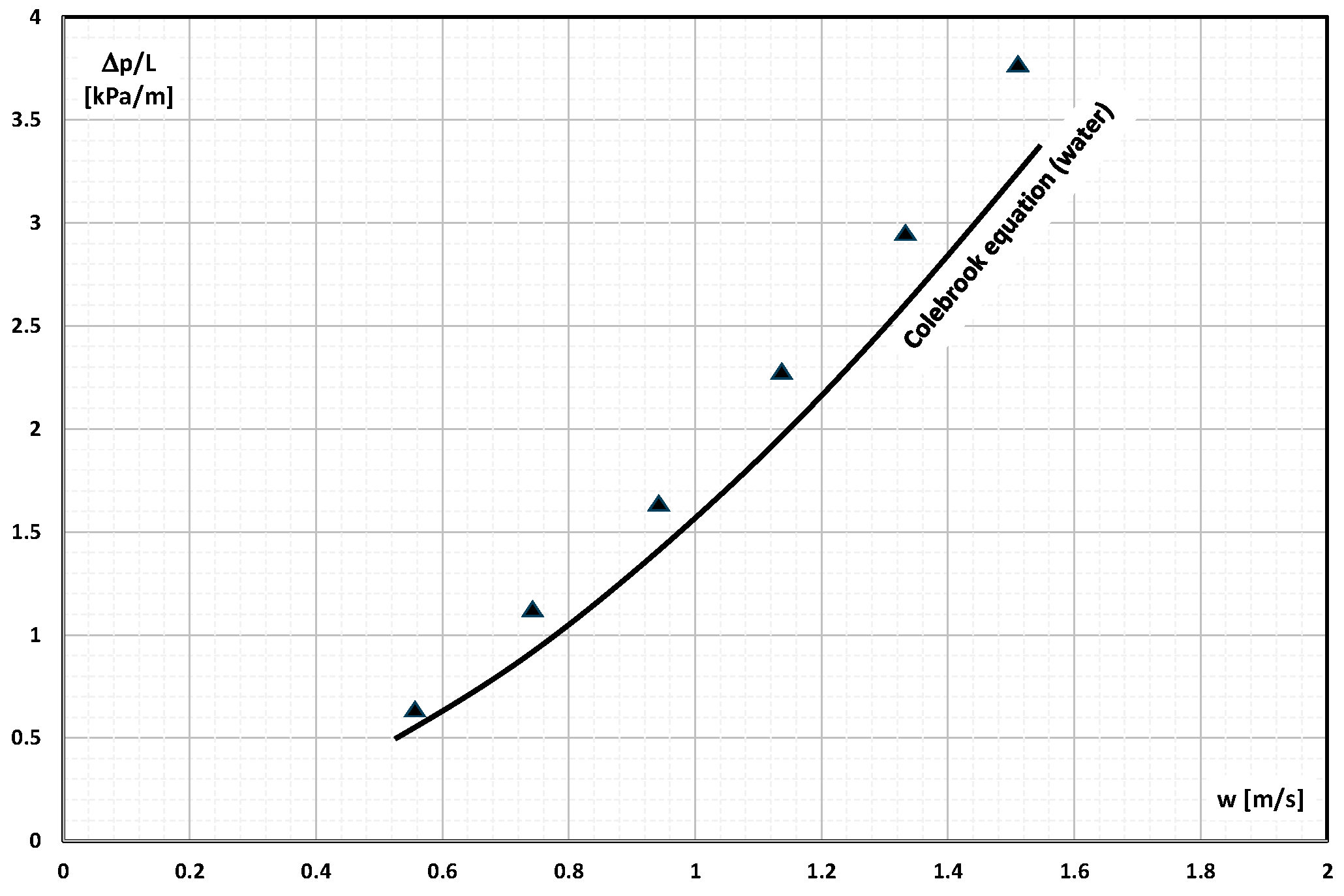
Micro-encapsulated n-tetradecane was also studied by Alvarado et al. [23]. Microcapsules of 2–10 µm, 70–260 µm, and 90–150 µm diameter were added at 4.6%, 5.9%, 8.3%, 13.4%, 16.1%, and 17.7 wt% into the water and flowed through a straight pipe with a length of L = 1520 mm and an internal diameter of d = 10.9 mm. The authors found that in the examined range of mPCM mass fraction, mPCM particle size, and Re = 3600–9800, their influence on the pressure drop was minimal (Figure 2), and the test results can be compared with the results of calculations according to the Colebrook correlation.
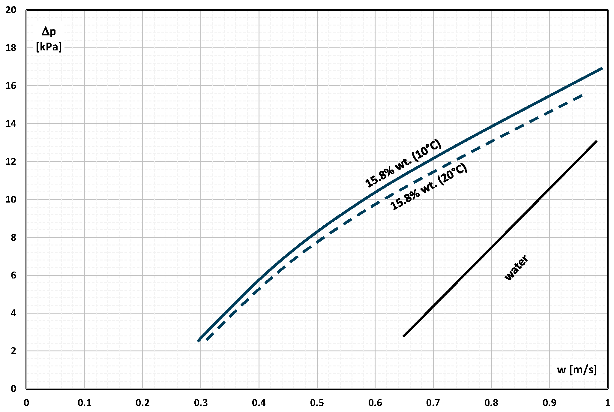
Chen et al. [24] conducted studies of the heat transfer and pressure drop of micro-encapsulated 1-bromohexadecane (C16H33Br). PCM with a phase-change temperature T = 14.3 °C was encased in an aminoplastic shell. Microcapsules with an average diameter of d = 8.20 µm were added to water in the amount of 5%, 10%, and 15.8% of the mass. The slurry at T = 10 °C and T = 20 °C (PCM in the microcapsule was in a solid or liquid state, respectively) flowed through a stainless steel tube. The internal diameter of the tube was d = 4 mm and its length L = 1460 mm. The authors found that the temperature of the slurry as well as the physical state of PCM did not significantly affect the pressure drop (Figure 3). The slurry at the temperature T = 20 °C caused about 10.3% lower pressure drop than at the temperature T = 10 °C, but it was still much denser than during the flow of water. The authors found that although the flow velocity of pure water and aqueous mPCM slurry was in a similar velocity range (w = 0.2–1 m/s), the water flowed turbulently, and the slurry flowed in a laminar flow.
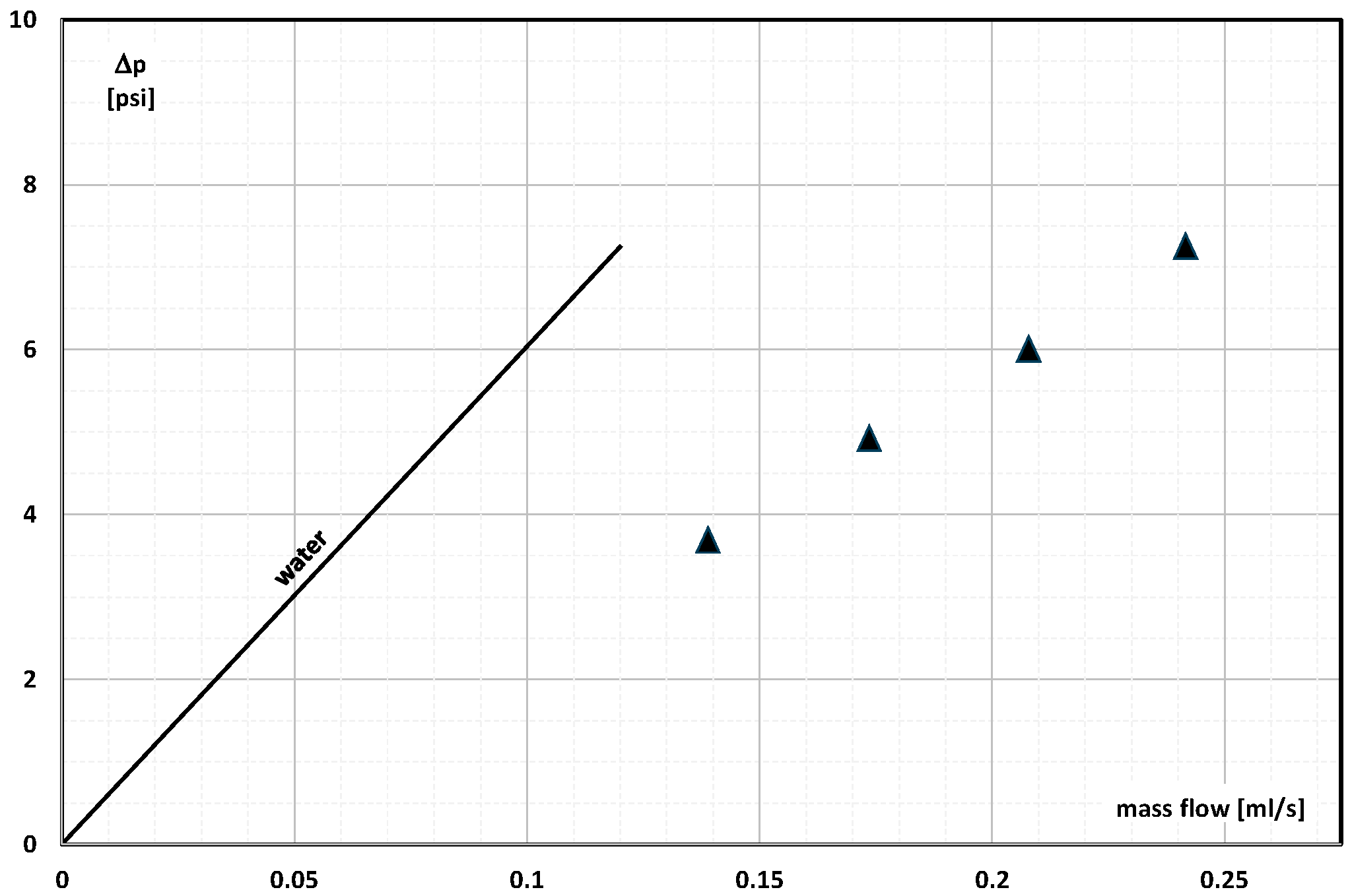
Damel et al. [25] conducted experimental studies and CFD simulations with the aim of determining the heat transfer and pressure drop of aqueous mPCM slurries in copper mini-channels. The aqueous slurry with 10% and 20% mPCM content flowed in a laminar manner through rectangular mini-channels. The mPCM particles had an average size of 5 μm. The PCM used was n-eicosane with a melting point of T = 36.4 °C in a polymethylmethacrylate (PMMA) coating. The heat exchanger consisted of nine parallel mini-channels. Each of them was 2 mm wide, 4.2 mm high, and 390 mm long. The results of the measurement of the pressure drop across the exchanger indicate (Figure 4) that the higher the concentration of mPCM, the greater the pressure drop. The experimental value of the pressure drop was lower than the results from the theoretical calculations. The authors explained this fact with the uneven distribution of mPCM particles in the flow. It was found that a layer poorer in microcapsules forms at the walls, and as a result, the pressure drop is lower than that resulting from theory.
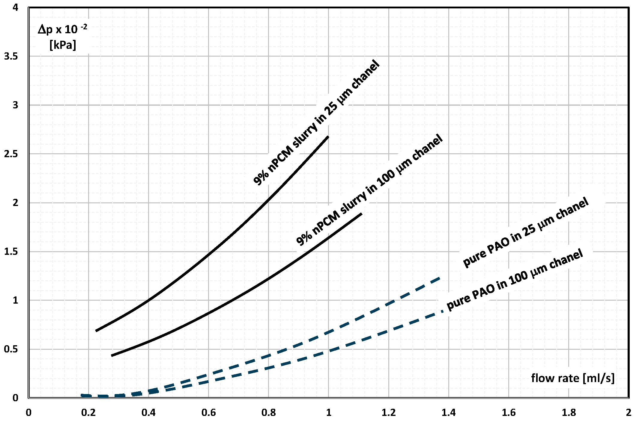
Wu et al. [26] published the results of the study of the pressure drop of synthetic oil (poly-alpha-olefin—PAO) with the addition of indium nanoparticles (melting point T = 155 °C) without and with a silica coating. The slurry of 9% and 30% particles of ~200 nm size and temperature of 19 °C flowed through a heat exchanger with microchannels 25 μm and 100 μm wide, 500 μm high, and 1000 μm long. The flow was varied in the range of 1–8 mL/s. It was found (Figure 5) that the pressure drop during the flow of the nPCM slurry was lower than that of the non-encapsulated PCM slurry (emulsion). In addition, the pressure drop was greater when the mPCM concentration was higher, and the hydraulic diameter of the microchannels through which the slurry was flowing was smaller.
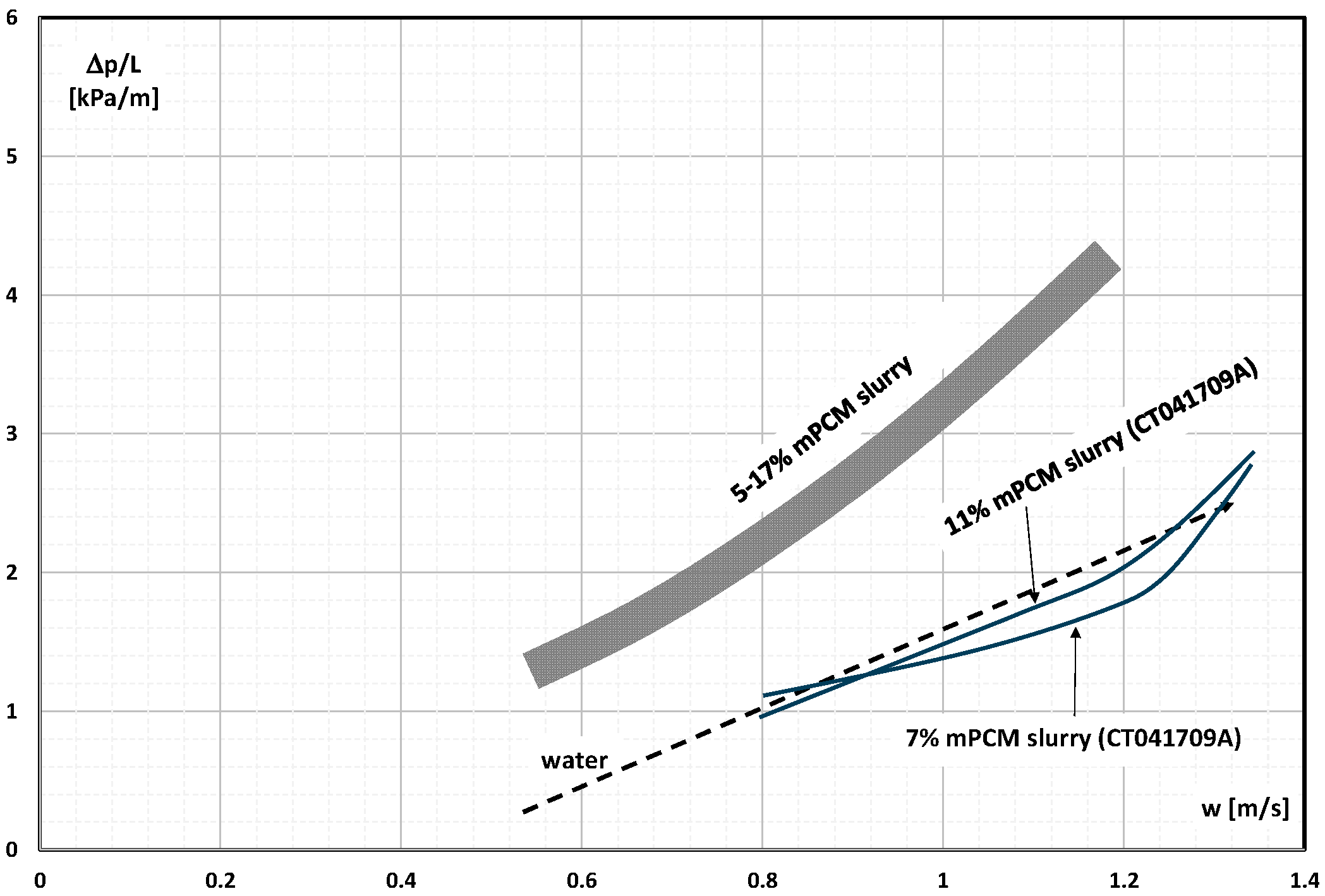
The study by Taherian et al. [27] included thermal and flow characteristics obtained during the study of the flow of six different slurries: five based on micro-encapsulated methyl stearate with different capsule sizes and a proprietary PCM designated as CT041709A. The flow of aqueous slurry of mPCM with a concentration of 5–17% took place in the range of Re = 3000–6000 inside a pipe with a length of L = 1.5 m and an internal diameter of d = 11 mm. The authors noted that the innovative product causes a pressure drop comparable to the pressure drop during the flow of pure water (Figure 6). The methyl-stearate-based slurries caused a significantly higher pressure drop regardless of the mPCM concentration. The low pressure drop of the proposed slurry, according to the authors [27], resulted from the fact that the resulting relative roughness of the channel wall became smaller in contact with their fluid.
Sinha-Ray et al. [28] studied the heat transfer and pressure drop of an aqueous slurry of carbon nanotubes. Some nanotubes contained wax and others meso-erythritol. The slurry, with the mass fraction of nano capsules up to 3%, flowed laminarly through a channel with a diameter of 603 μm or 1803 μm and a length of 50 mm. The results of the measurement of the pressure drop during the slurry flow (Figure 7) indicated that they were lower than in the case of the water flow. The authors explained this by the need to add a surfactant to the nPCM slurry. It was found that the greater it was, the lower the pressure drop.
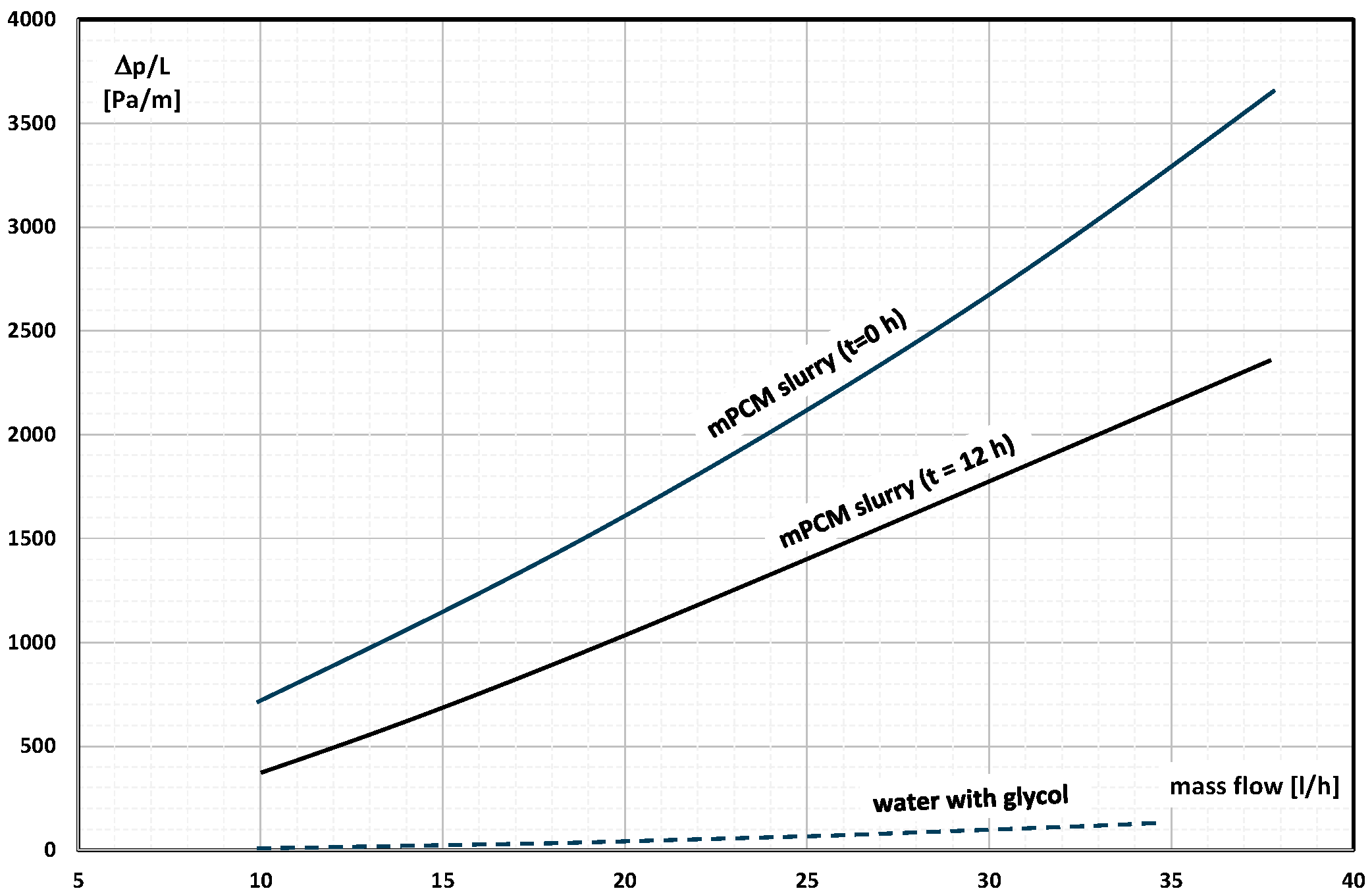
Serale et al. published a paper [29] devoted to the possibility of using the mPCM slurry in the solar collector cycle. The slurries consisted of 25–45 wt% micro-encapsulated n-eicosane (melting point T = 36–38 °C) with a size of 17–20 μm. The pressure drop in the flow of slurries in a pipe with dimensions similar to the dimensions of the pipes from which the liquid solar collector was built was determined. The most appropriate concentration of mPCM in the solar collector loop was found to be 40%. An increase in the flow rate of the slurry (Figure 8) caused an increase in pressure drop, but the pressure drop measured after 12 h of operation of the installation decreased by 30%. The reason was supposed to be the creaming phenomenon of the slurry and the outflow of mPCM as a matter of lower density.
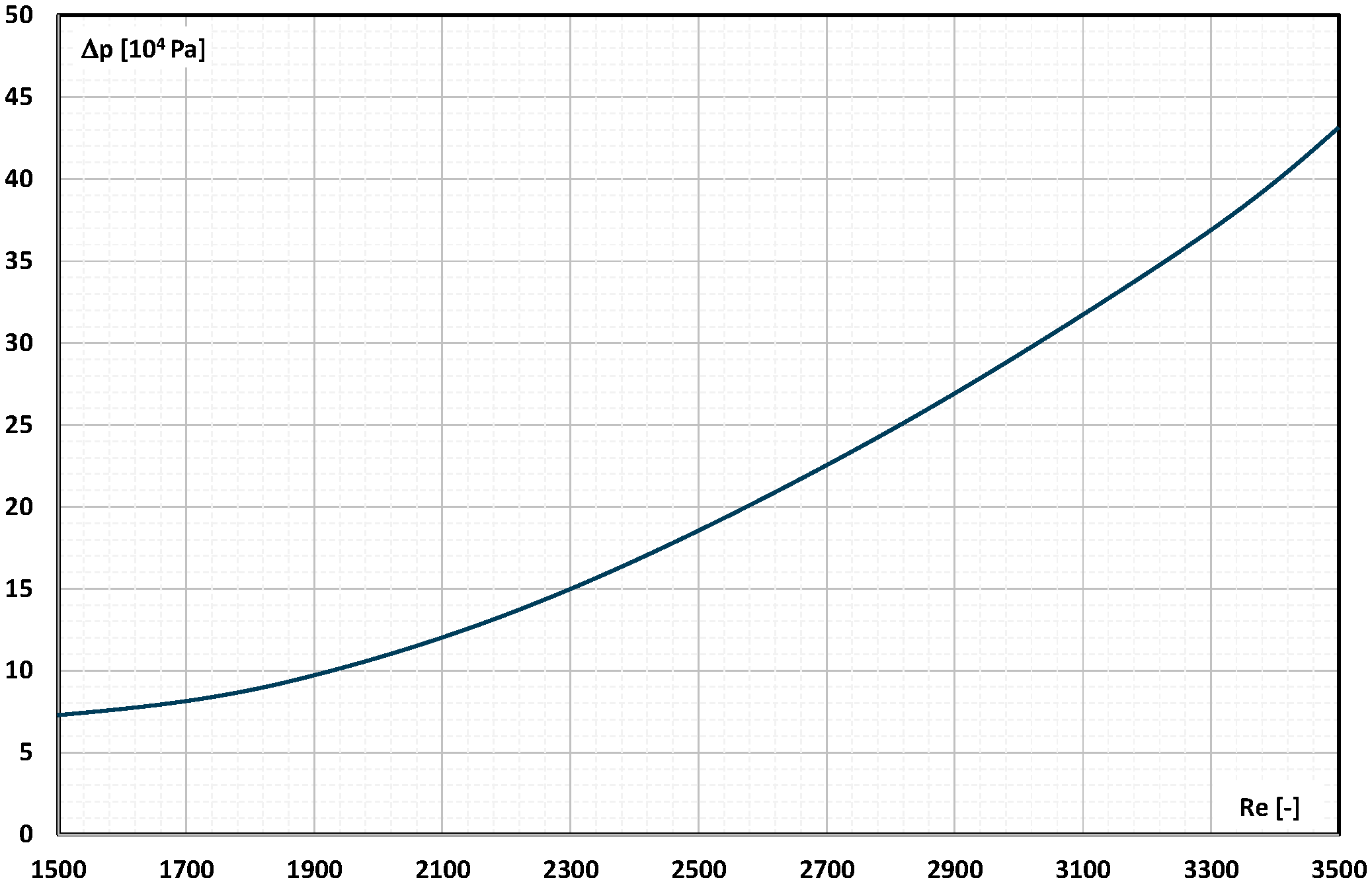
Qiu et al. [30] described the results of the study of the possibility of increasing the efficiency of the PV/T module by using the mPCM slurry to cool the cells. A product of Microtech Laboratories Inc. with the trade name MPCM-28 (paraffin with a phase-change temperature T = 28 °C enclosed in polymer microcapsules of the average size of 18.2 μm) was used to create an aqueous slurry. The mass fraction of mPCM in the slurry was 5%, 10%, and 15%. The slurry flowed in the panel cooling system in the range of Re = 1508– 3496. The characteristics of changes in pressure drop during the flow of 5% slurry with a serpentine arranged on the back surface of the panel wall are shown in Figure 9. The increase in the flow velocity of the slurry resulted in an increase in pressure drop. The authors also stated that the higher the concentration of mPCM, the greater the pressure drop.
The flow of 1% and 2% aqueous slurry of mPCM through a heat exchanger composed of 10 parallel mini-channels with dimensions of 0.35 mm wide, 0.35 mm deep, and 440 mm long was the subject of research by Wang et al. [31]. The slurry based on microcapsules with an average size of 1 μm containing paraffin as PCM and a coating of melamine-formaldehyde resin flowed through mini-channels in the Re < 800 range. The researchers described the results of thermal and flow measurements. The measurements of the pressure drop showed (Figure 10) that they increased in direct proportion to the Re number. The mass fraction of mPCM in water influenced the pressure drop. Already for 1% of the mPCM, the slurry pressure drop was about 80% higher than in the case of water.
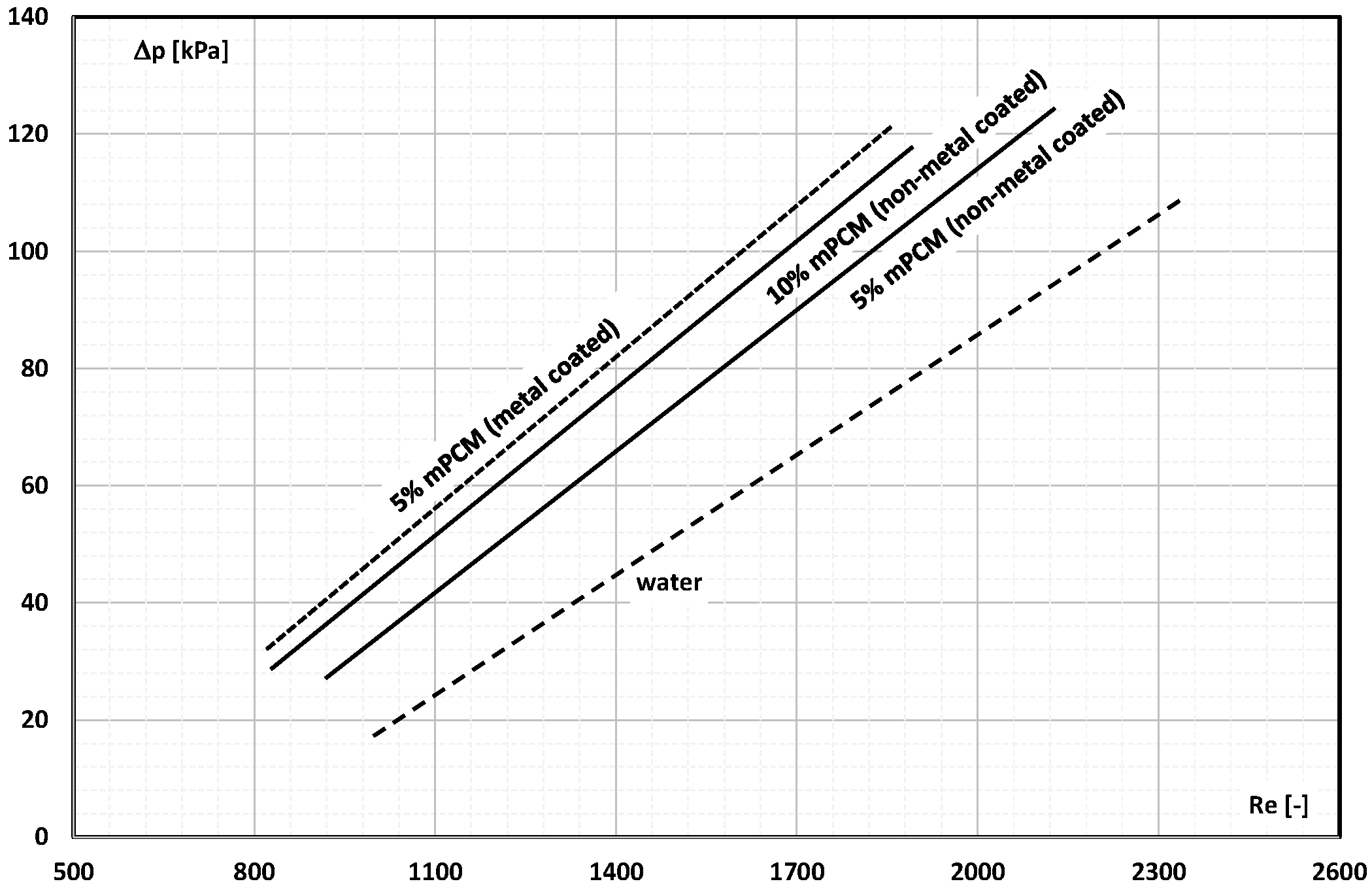
Studies on the effect of mPCM slurry where capsules have additional coating with an metal sheath (or without a sheath) were described by Roberts et al. [32]. Rubitherm RT 21, a paraffin, was encapsulated in microcapsules made of a polymer coating made of cross-linked poly methyl methacrylate (PMMA). Some of the microcapsules were additionally covered with a layer of silver (Ag). Microcapsules with an average diameter of 7.82 µm (without Ag coating) and 8.06 µm (with Ag coating) were added to water to form 5% and 10% mPCM slurries. The slurries flowed through a stainless steel tube with an internal diameter of 0.76 mm and a length of 100 mm or 620 mm. The Re range was from 800 to 2300. It was found that the addition of 5% mPCM without Ag coating to water increased the pressure drop by an average of 50%, and in the case of a 10% slurry, the increase was already 60% (Figure 11). The pressure drop of the Ag-coated mPCM slurry was even higher. A 70% increase in pressure drop was recorded during the flow of 5% mPCM slurry in relation to the flow of water.
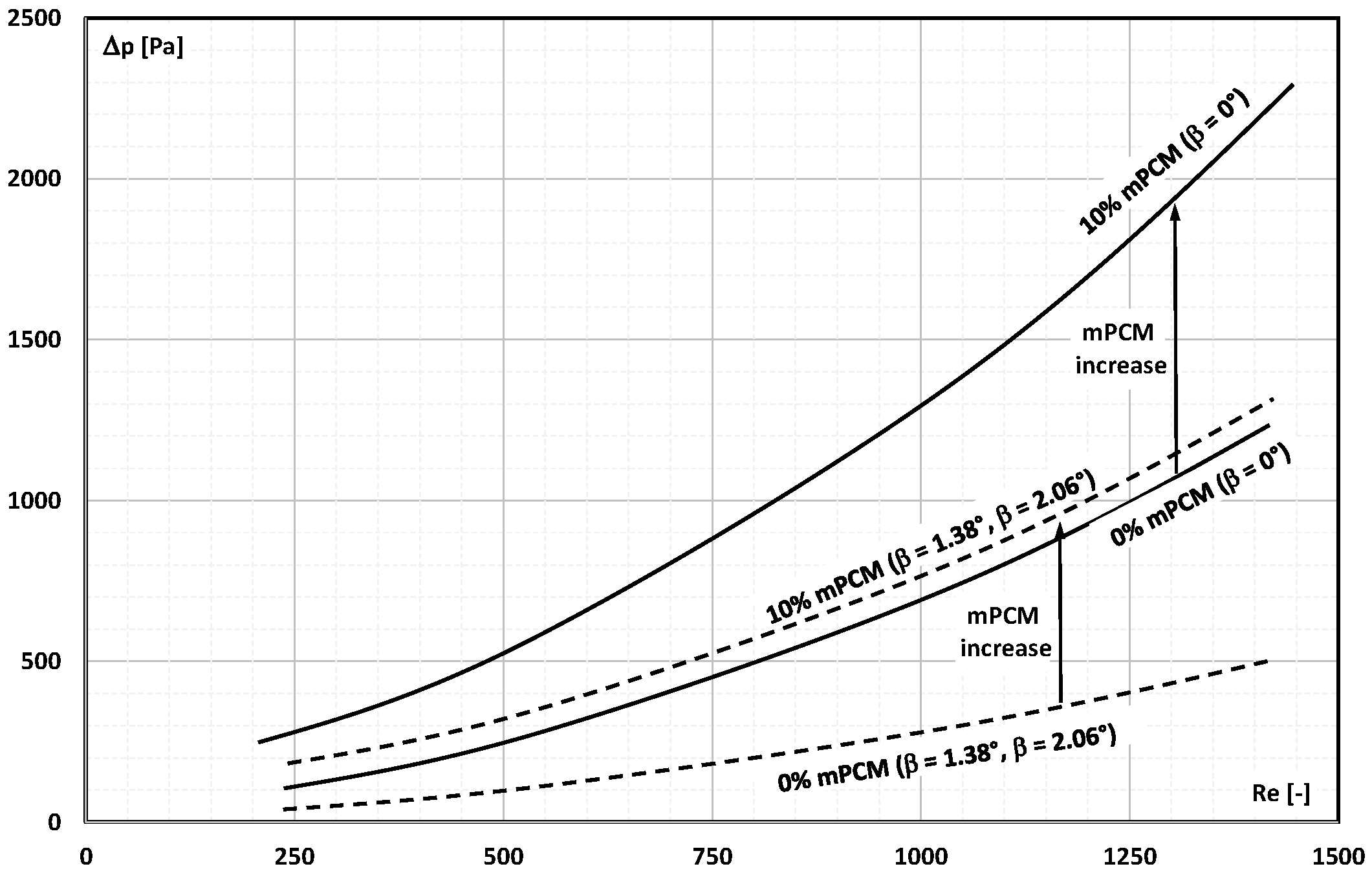
The pressure drop of slurry with a mass fraction of 2%, 5%, and 10% of mPCM was the subject of a paper published by Ho et al. [33,34]. The mPCM slurry flowed through a heat exchanger with parallel and diverging channels. Diverging channels 50 mm long, 1.5 mm deep, and 1 mm wide at the exchanger inlet had different opening angles (β = 1.38° and β = 2.06°). The slurry flow through the mini-channels was in the range of Re = 238–1375. It was found that the use of divergent channels results in a significant decrease in the slurry’s pressure drop. The influence of the divergent channel on pressure drop became more pronounced the higher the flow (Figure 12). In each case, the pressure drop was higher with an increasing concentration of mPCM in the slurry. In their subsequent studies [35], the authors added Al2O3 nanoparticles to the mPCM slurry. They found that the thermal and flow effects strongly depend on the Reynolds number and the physical state of the PCM in the microcapsule. For low Re values, i.e., when the PCM had time to melt, the thermal and flow effects were more promising.
In the study by Zhang et al. [36], a 2.4 m long copper pipe with an internal diameter of 10 mm was used to flow an aqueous slurry of micro-encapsulated paraffin. The mPCM particles (DS5001X from BASF) with a melting point of 26.5 °C had a highly cross-linked polymethyl methacrylate (PMMA) shell and an average particle size of 7 μm. The mass fraction of the microcapsules in the aqueous slurry was 5% and 10%. The pressure drop measurements indicated that the addition of mPCM to water did not increase the pressure drop for the same average fluid flow velocity. Figure 13a shows that when the speed was changed in the range of 0.5–2.5 m/s, the Reynolds number changed in the range of Re = 5377–23,590 (for water), Re = 3770–16,689 (5% mPCM slurry), and Re = 1148–5637 (10% mPCM slurry). It can therefore be presumed that for analogous values of the Reynolds number, the value of pressure drop was higher in the case of mPCM slurries. Also, adding 1% of the mass of various metal particles (ZnO or nano ZnO or nano Al2O3) [37] to the slurry did not affect the pressure drop measured during their flow (Figure 13b).
The paper by Pakrouh [38] described the results of CFD simulations of the use of mPCM slurry (water slurry of micro-encapsulated n-octadecane) for cooling electric car batteries. A pack of 186 batteries was cooled with a liquid flowing in a serpentine system similar to the one used in the Tesla S car. The influence of mPCM slurry concentration (10% and 20%) and fluid velocity (up to 0.4 m/s) on the pressure drop and heat transfer were examined. The simulation results showed (Figure 14a) a negative impact of the mass fraction of mPCM on the pressure drop regardless of the slurry flow velocity. Similar conclusions resulted from the results of the CFD simulations presented in [39,40,41,42]. The simulation results described in [43] contradict these data. It was shown that the higher the concentration of the mPCM slurry adopted for the simulation, the lower the pressure drop (Figure 14b).
Also, according to some experimental results described in [44], the slurry’s pressure drop across the serpentine pipe of PV/T module remained in a downward trend when the mPCM concentration ratio grew from 0% to 10%. When the test results for the same Re number values were compared, it turned out that, as expected, the higher the concentration of mPCM, the higher the pressure drop in the slurry flow.
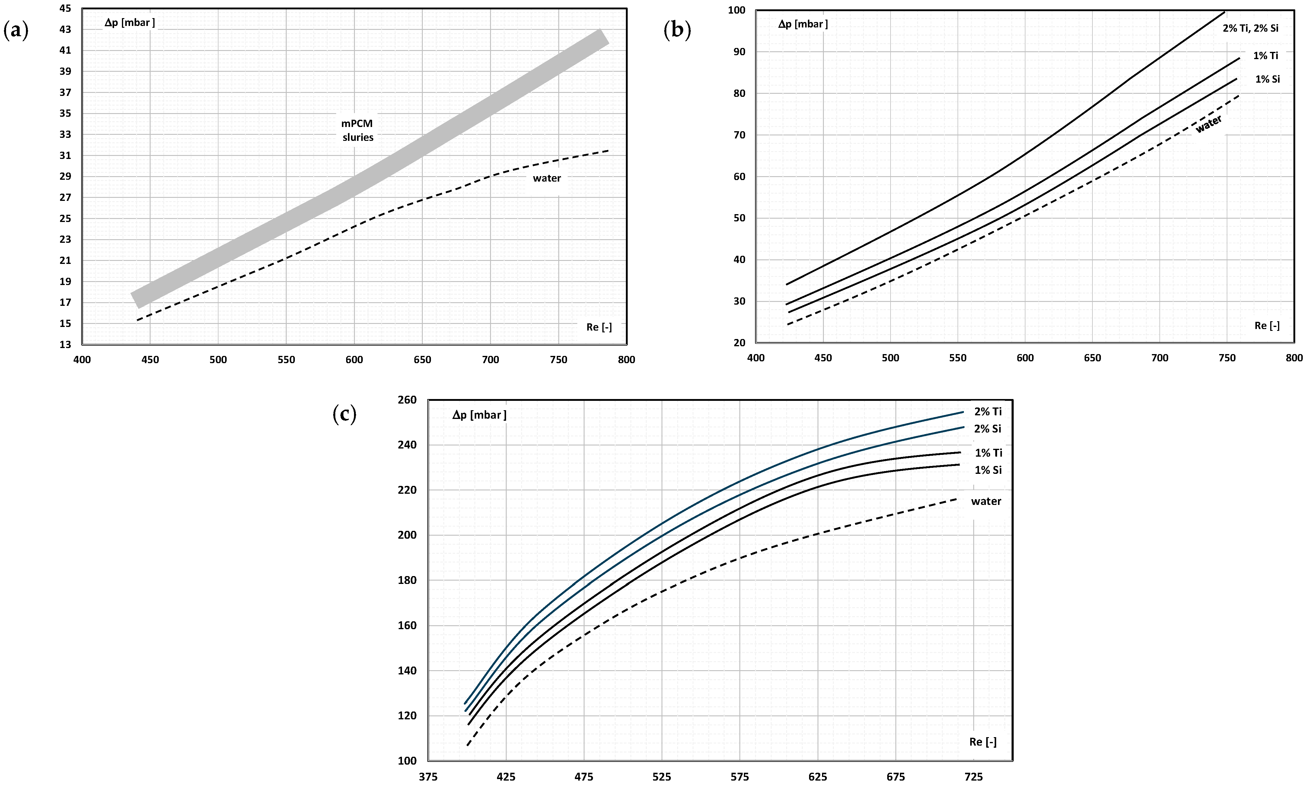
Papers [45,46] described the experimental data on the heat transfer and pressure drop of the mPCM slurry flow through the radiator. The slurry consisted of deionized water and 1% and 2% by the weight of the microcapsules. The core material of the microcapsule was paraffin with a melting point of 55.7 °C, and the shell was silica (Si) and titanium (Ti). The tests were carried out in the range of Re = 400–850. The 30 mm × 40 mm heat sink had several parallel straight, microchannels, segmental microchannels, a combination of straight and segmental microchannels [45], and wavy and zigzag microchannels [46]. The radiator was in contact with the heater with adjustable power. In the heat sink with parallel microchannels, the pressure drop during the slurry flow (Figure 15a) was higher by about 28% compared to the water flow. In this case, no clear influence of the type of coating material or slurry concentration on the value of pressure drop was recorded. The differences were clear when the slurry flow was carried out with a radiator with segmented channels and a combination of segmented and straight channels (Figure 15b). Then, the higher the concentration of microcapsules, the higher the pressure drop values. In the range of laminar flow of working liquids, the increase in Re number caused a linear increase in the value of pressure drop. In channels with a wavy course, the increase in the flow velocity caused an increase in the pressure drop, but the increase was smaller the higher the Re number was (Figure 15c).
Summarizing the test results presented in this section, one thing is consistent: the greater the measured mPCM slurry flow, the greater the measured pressure drop. This relationship was observed regardless of the physical quantity (flow velocity, flow rate, and Reynolds number) assumed in the graph as an independent variable. The increase in pressure drop was directly proportional when the slurry flow was laminar (linear characteristics) or power-law when the slurry flow was turbulent (parabola-shaped characteristics). These results are in line with expectations and do not go beyond the current knowledge of fluid mechanics. However, individual cases indicate a different course of characteristics. The probable cause is the introduction of agents into the mPCM slurry, the exact composition and mass fraction of which is often a secret of the manufacturer. Because of this, it is difficult to recognize the influence of additives on the obtained flow characteristics.
Less obvious conclusions result from the study of the effect of the mass of PCM microcapsules in slurry on the pressure drop. The conclusions are different depending on the method of data presentation (physical quantity assumed on the axis of abscissa). In practice, for comparative reasons, the characteristics presented as a function of the Reynolds number are important. They give the opportunity to compare the results obtained using fluids of different viscosities and densities. Then, it is beyond any doubt that the addition of mPCM to the base liquid causes an increase in flow resistance (at the same Re number). The increase in resistance is greater the higher the concentration of mPCM.

3. Friction Factor

The measurement of the pressure drop during the flow of a fluid is a characteristic of the fluid, the installation through which it flows, and the flow conditions. The comparison of the results of various authors presented in the form of characteristics of pressure drop versus flow velocity or flow rate is rather informative and makes it difficult to draw generalized conclusions. For this reason, it is expected to present the results of flow tests in the form of characteristics in a dimensionless coordinate system. This chapter presents an overview of articles in which the results of research on the loss coefficient (friction factor) from the Reynolds number have been published. The analysis of the research results presented in this form makes it possible to generalize the conclusions on how the selected parameters (mPCM size, mPCM concentration, PCM type, capsule shell material, type of base liquid, etc.) affect the behavior of the fluid in the flow.
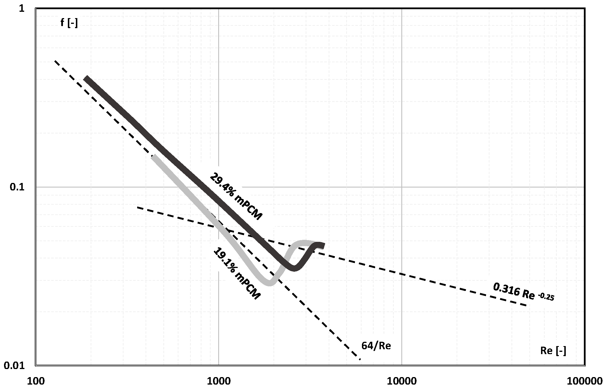
Yamagishi et al. [47] described the results of thermal and flow tests of the mPCM slurry based on two types of paraffin: n-tetradecane with a phase-change temperature of T = 5.5 °C and n-dodecane with a phase-change temperature of T = –13.5 °C. The PCM was contained in melamine resin microcapsules of four different sizes: 5 µm, 30 µm, 250 µm, and 1000 µm. Water and water brine (in the case of PCM with a negative phase-change temperature) were used as the base liquid. The volume fraction of microcapsules in the slurry was 7.3%, 19.1%, and 29.4%. The slurry flowed through a tube with an internal diameter of d = 10 mm and a test length of L = 800 mm. The flow tests showed that only the smallest microcapsules had sufficient strength to be used in pump circuits. The friction factor for the laminar flow of the slurry of mPCM capsules with a diameter of 5 µm and the highest concentration (Figure 16) was higher than the values assumed for the Newtonian fluid. The change in the type of fluid flow took place in the range of Re = 2000–3000. The lack of test results for Re > 3000 did not allow to determine how the value of the friction factor in turbulent flow of the mPCM slurry is formed.
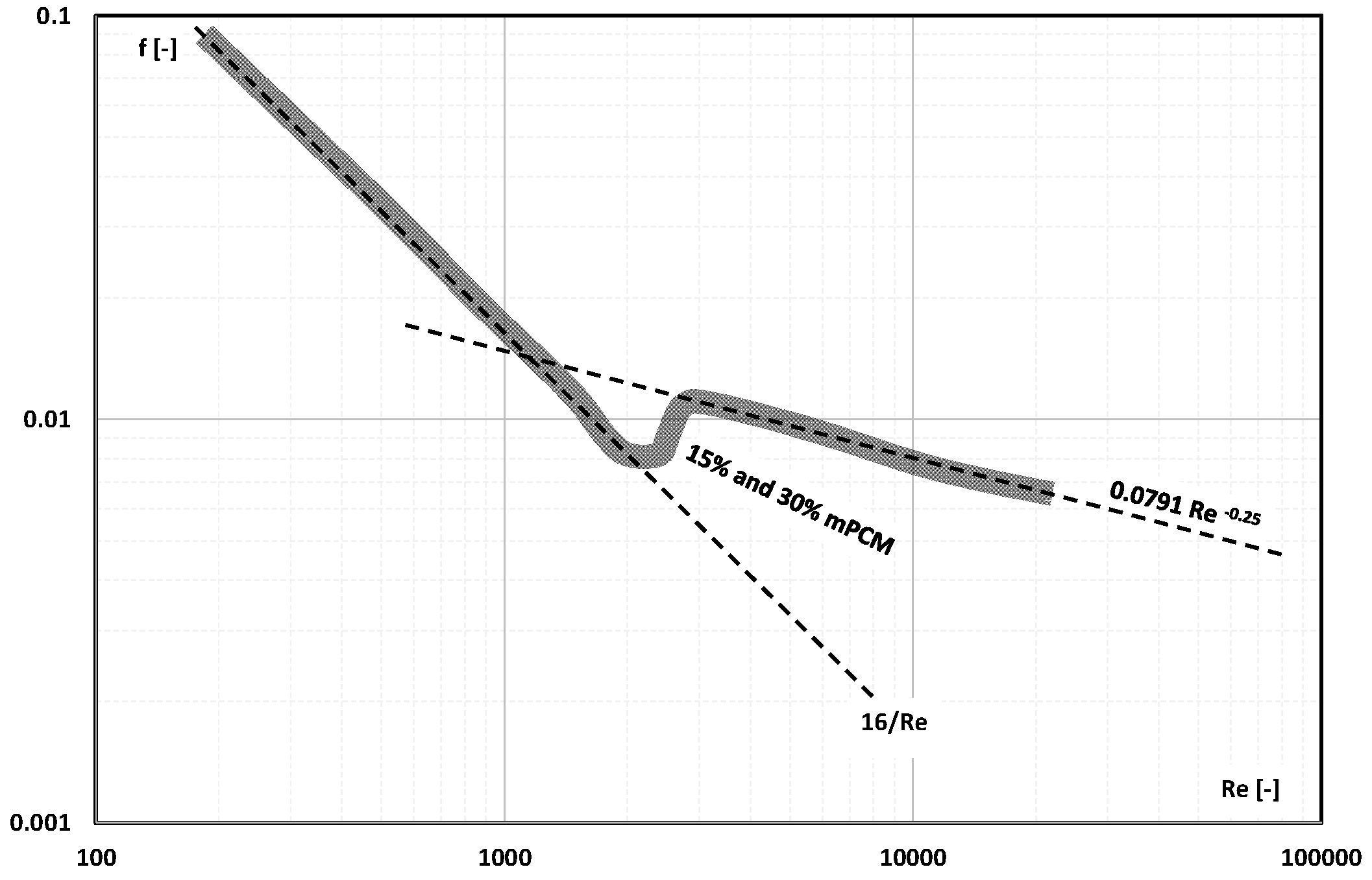
The authors of [48] used microcapsules filled with octadecane (C18H38) with phase=change temperature T = 28 °C. Microcapsules with dimensions of 2–10 µm had a wall made of melamine–formaldehyde resin. The volume fraction of mPCM in water was 7, 12, 15, 25, and 30%, respectively. The mPCM slurry flowed through a tube 10.1 mm in diameter and 1050 mm in length. The slurry flow was changed in the range of 4.0–7.5 L/min, covering the range of laminar and turbulent flow. The tests of the adiabatic flow of water and slurry with a concentration of 15% and 30% mPCM showed (Figure 17) that the Fanning factor assumed values as for the Newtonian fluid. As a result, the authors of the publication proposed that the loss coefficient of the laminar slurry flow should be described by the Hagen–Poiseuille equation, and that of the turbulent flow by the Blasius equation. The change from laminar to turbulent motion took place in the range Re = 2000–3000.
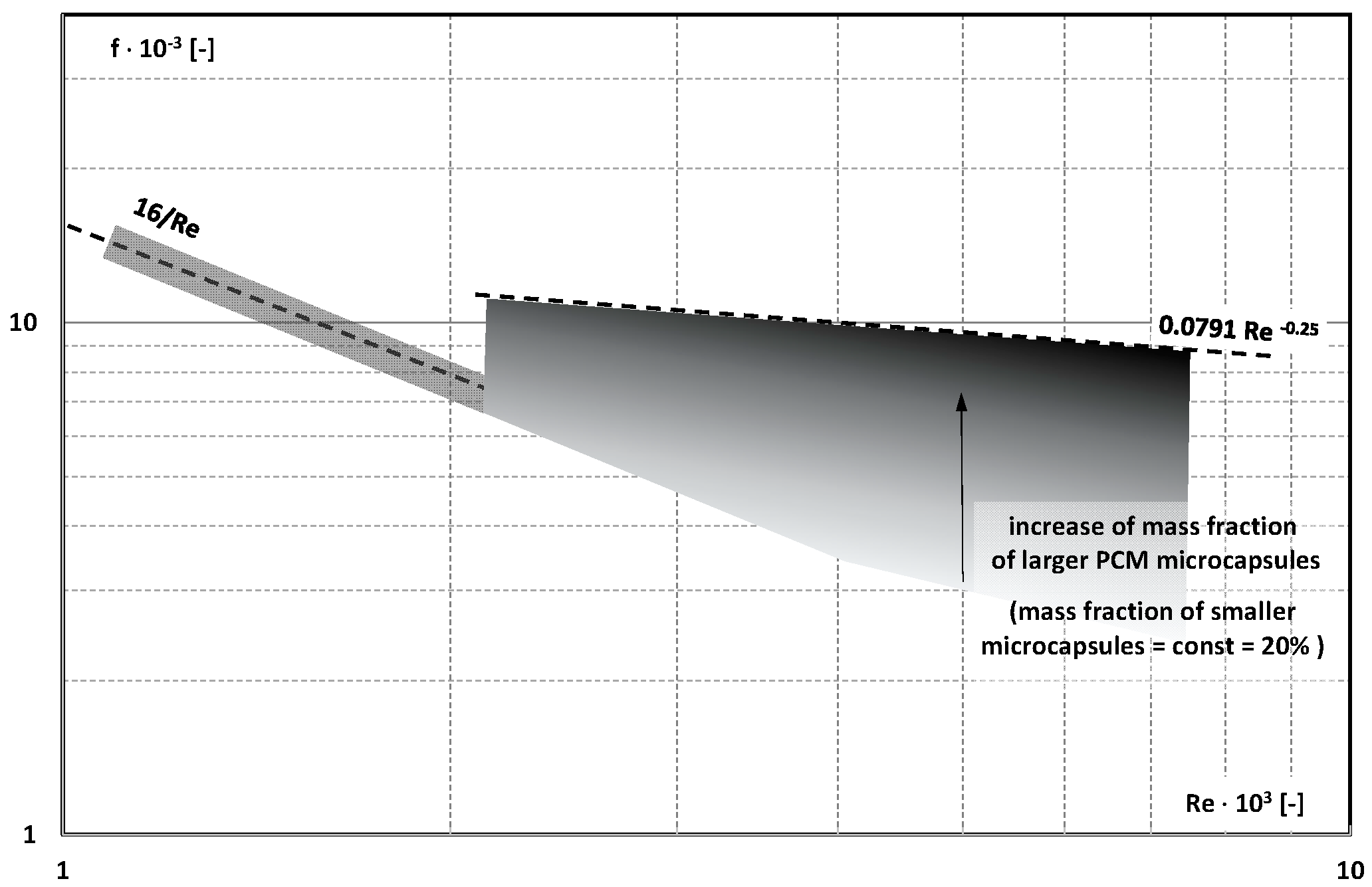
Paper [49] presented the results of testing the pressure drop of an aqueous slurry composed of PCM microcapsules of two different sizes. Smaller microcapsules with a size of 1.5 µm were filled with n-tetradecane (C14H30) with a phase-change temperature of T = 278.9 K. Larger microcapsules with a diameter of 17 µm were filled with n-docosane C22H46 with a phase=change temperature of T = 318.2 K. The mass fraction of smaller microcapsules in the slurry was constant and amounted to about 20%. The mass fraction of larger microcapsules in relation to smaller microcapsules was 10, 20, 30, 40, and 50%. The slurry flowed through a pipe with an internal diameter of d = 16 mm and a length of L = 5.85 m. The temperature of the slurry was always lower than the phase-change temperature of n-decosane (T < 318 K). The obtained value of the linear loss coefficient as a function of Re is presented graphically in Figure 18. The authors stated that in laminar flow, the Fanning factor can be described as for a Newtonian fluid. In turbulent flow, a clear influence of the mass fraction of larger PCM microcapsules on the Fanning factor was noticed. In the absence of large microcapsules, the friction factor was lower than the Hagen–Poiseuille equation. The higher the share of large microcapsules in the slurry, the higher the value of the loss coefficient, with tendencies for the value as for the flow of turbulent Newtonian fluid through smooth pipes.
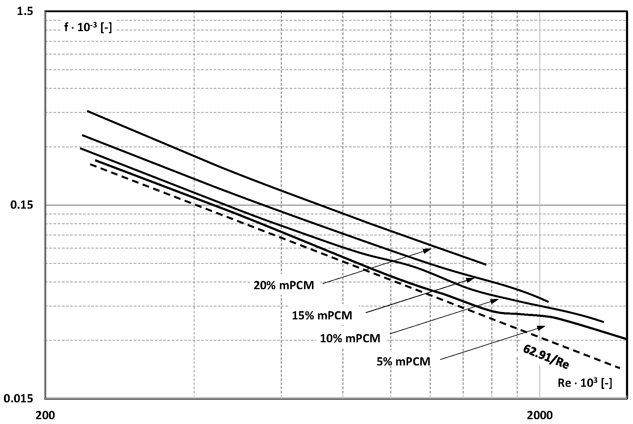
The paper by Rao et al. [50] presented the results of thermal and flow tests of the mPCM water slurry in an electrically heated mini-channel with a square cross-section (2 mm × 4.2 mm × 150 mm). The slurry was composed of microcapsules with an average size of 4.97 µm containing n-octadecane (phase-change temperature T = 28 °C) in a coating of polymethyl methacrylate (PMMA). Slurry 5, 10, 15, and 20 wt% flowed through the mini-channel in the range of Re = 200–2000. Experimental studies of the friction factor of the slurry showed (Figure 19) that the 5% mPCM slurry behaved like a Newtonian fluid; the friction factor can be described by the Hagen–Poiseuille law, and the change to turbulent flow followed after exceeding Re = 2000. In other cases, the friction factor was higher by 30%, 48%, and 75%, respectively, for the slurry of 10%, 15%, and 20%. The authors explained this fact due to the increase in slurry viscosity with the increase in mPCM concentration.
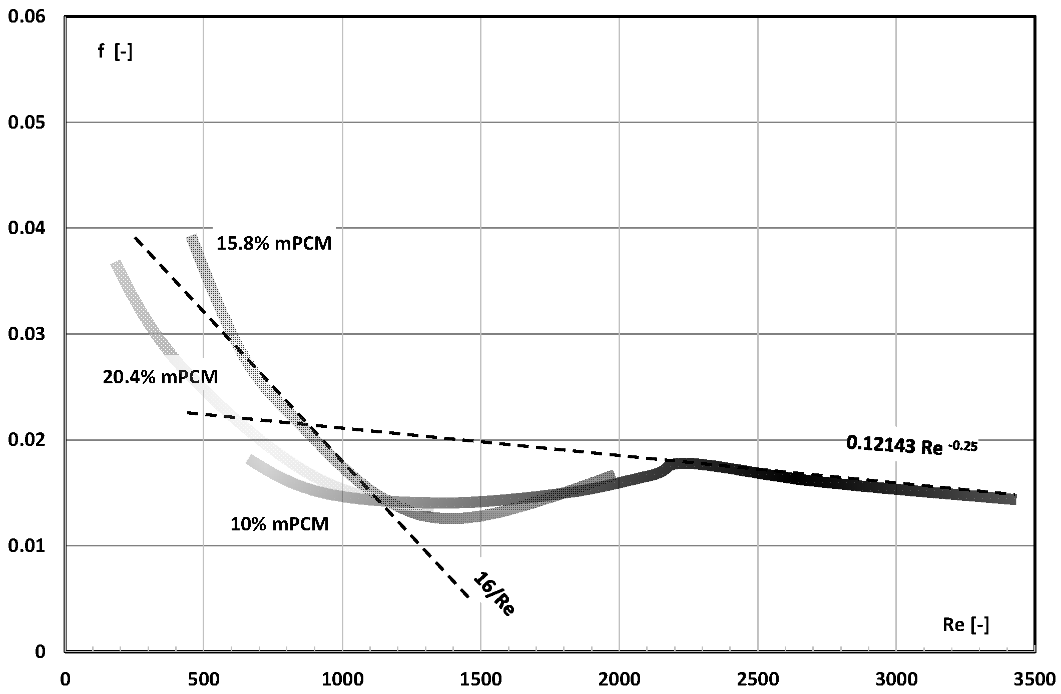
Wang et al. [51] published experimental data on thermal and flow tests of a slurry of micro-encapsulated 1-bromohexadecane (C16H33Br). PCM with a phase-change temperature T = 14.3 °C was encased in an aminoplastic shell. Microcapsules with an average diameter of 10.112 µm were added to water in the amount of 5%, 10%, 15.8%, 20.4%, and 27.6% by weight. The slurry at T = 20 °C (PCM in the microcapsule was in a liquid state) flowed through a stainless steel tube. The internal diameter of the tube was d = 4 mm and its length L = 1.46 m. The measurements of pressure drop allowed to determine the friction factor in the range of laminar, transitional, and turbulent slurry flow (Remax = 3452). The test results (Figure 20) indicated that the turbulent flow took place when Re > 2200. The change from laminar to turbulent flow took place in the range of Re = 1200–2200. In turbulent flow, regardless of the mPCM slurry concentration, the value of the friction factor was higher than the results from the Blasius correlation. The authors explained this fact by the pipe wall roughness. Probably, the pipe wall roughness was high, and there was no flow as in a hydraulically smooth pipe. In the range of laminar flow (Re < 1200), an increase in the Reynolds number caused a decrease in the friction factor, and its values were lower than those resulting from the Hagen–Poiseuille equation. The exception was the 15.8% concentration of mPCM. Then, the value of the friction factor was consistent with the Hagen–Poiseuille equation.
Ho et al. [52] indicated that the Fanning factor obtained for the laminar flow (Re = 133–1515) of an aqueous slurry of micro-encapsulated octadecane (C18H38) with a phase-change temperature T = 28 °C depended on the concentration of mPCM in the liquid. An aqueous slurry of PCM microcapsules sized 4–10 µm and in concentrations of 3.7%, 9.1%, and 18.2% (the share of pure PCM in the slurry was 2%, 5%, and 10%, respectively) flowed through an electrically heated mini-channel 50 mm long, 1 mm wide, and 1.5 mm high. The authors found that the higher the mPCM slurry concentration, the higher the fluid viscosity and hence the pressure drop and, consequently, the friction factor (Figure 21). It was also noticed that the addition of 10% Al2O3 nanoparticles to the mPCM slurry caused another increase in the pressure drop of the slurry [53] and hence the value of the friction factor (Figure 21).
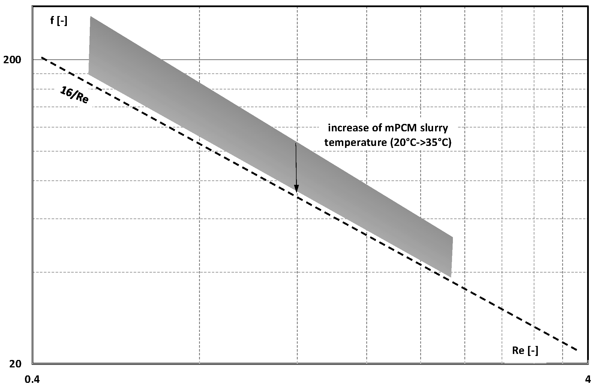
Cao et al. [54] published the results of a study on the pressure drop of a synthetic oil–poly-alpha-olefin (PAO) with the addition of paraffin wax particles (n-octadecane, C18H38, melting point T = 28 °C) in a melamine–formaldehyde resin coating. The size of the mPCM ranged from 5 µm to 15 µm, and their share in the slurry was 20% by weight. In order to increase the thermal conductivity of the slurry, the microcapsules were covered with a layer of silver. Three slurries, differing in the amount of silver on the shell surface and its roughness, were created. The slurry flowed through mini-channels 0.25 mm wide, 2.5 mm high, and 10 mm long. Pressure drop measurements were carried out during the flow of oil, oil–PCM emulsion, oil–mPCM slurry, and different temperatures (20 °C, 25 °C, 30 °C, and 35 °C). The flow was in the laminar range (Re < 4). Based on the measurements, the value of the friction factor was determined (Figure 22). The friction factor of the mPCM slurry at 20 °C was about 50% higher than the theoretical value. At 35 °C, i.e., when the PCM in the microcapsules was in the form of a liquid, the friction factor was only about 10% higher than the theoretical calculations.
Also, a paper by Song et al. [55] presented the results of hydrodynamic studies of mPCM slurry in a liquid metal: gallium. Eicosane (C20H42) with a melting point T = 36.4 °C was surrounded by a melamine–formaldehyde coating. Microcapsules of medium size, i.e., 12 µm, were added to gallium in the amount of 10%, 15%, and 20% by weight. In order to avoid interactions at the interface between the liquid and the mPCM shell, the microcapsule shell was covered with a layer of copper. The mPCM slurry flowed inside a tube of length L = 300 mm and internal diameter d = 4 mm. Figure 23 shows the relationship between the Fanning friction and the Re number. It was observed that the value of the friction factor of mPCM slurries changed in accordance with the values as for the Newtonian fluid (f = 16/Re) with a maximum relative error of 8.7%.
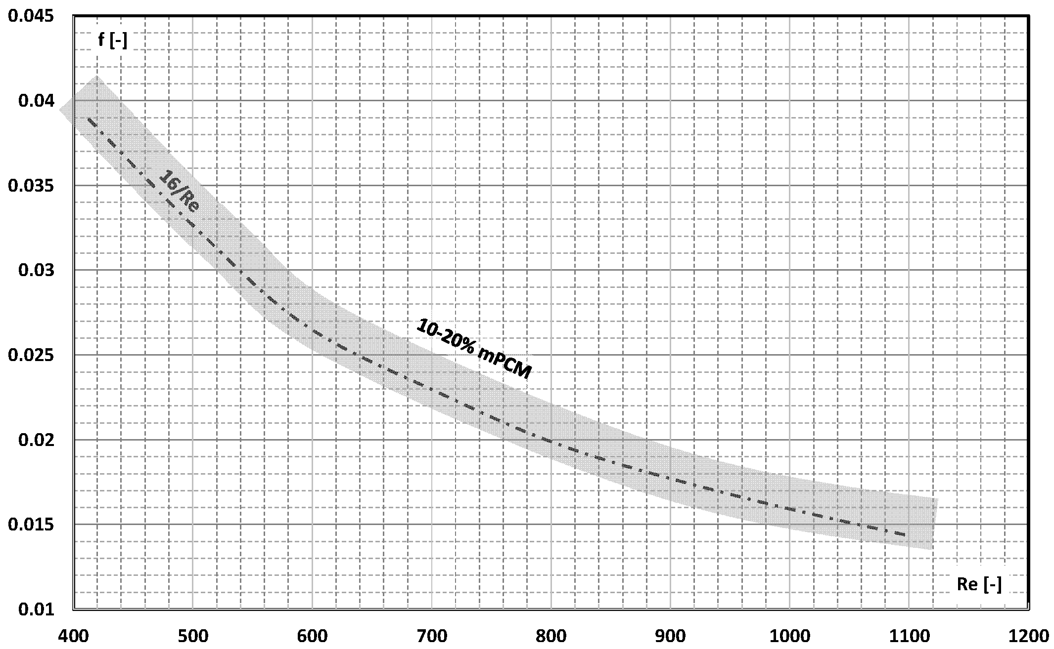
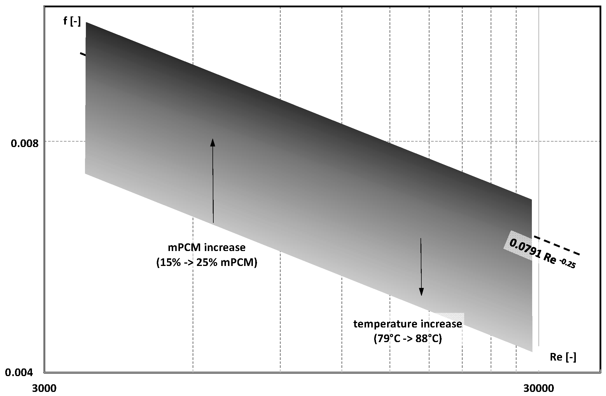
The Fanning factor of aqueous mPCM slurries was also described in the paper by Li et al. [56]. Paraffin particles with a phase-change temperature in the range of 78–85 °C were enclosed in a urea–formaldehyde resin shell. The microcapsule size was less than 10 μm. In order to improve the thermal conductivity of the slurry without increasing its viscosity, a composite PCM microcapsule material (CMPCM) was also prepared by introducing graphene into its sheath. A slurry with a mass concentration of 15%, 20%, and 25% and a temperature of 79 °C, 83 °C, and 88 °C flowed turbulently inside a steel pipe with an internal diameter of 8.0 mm and a length of 1.2 m. Figure 24 shows the results of the Fanning factor versus the Reynolds number. It was found that in the vast majority of cases, the friction factor was lower than the results from the Blasius equation. The higher the concentration of microcapsules, the higher the friction factor and the closer to the classical values.
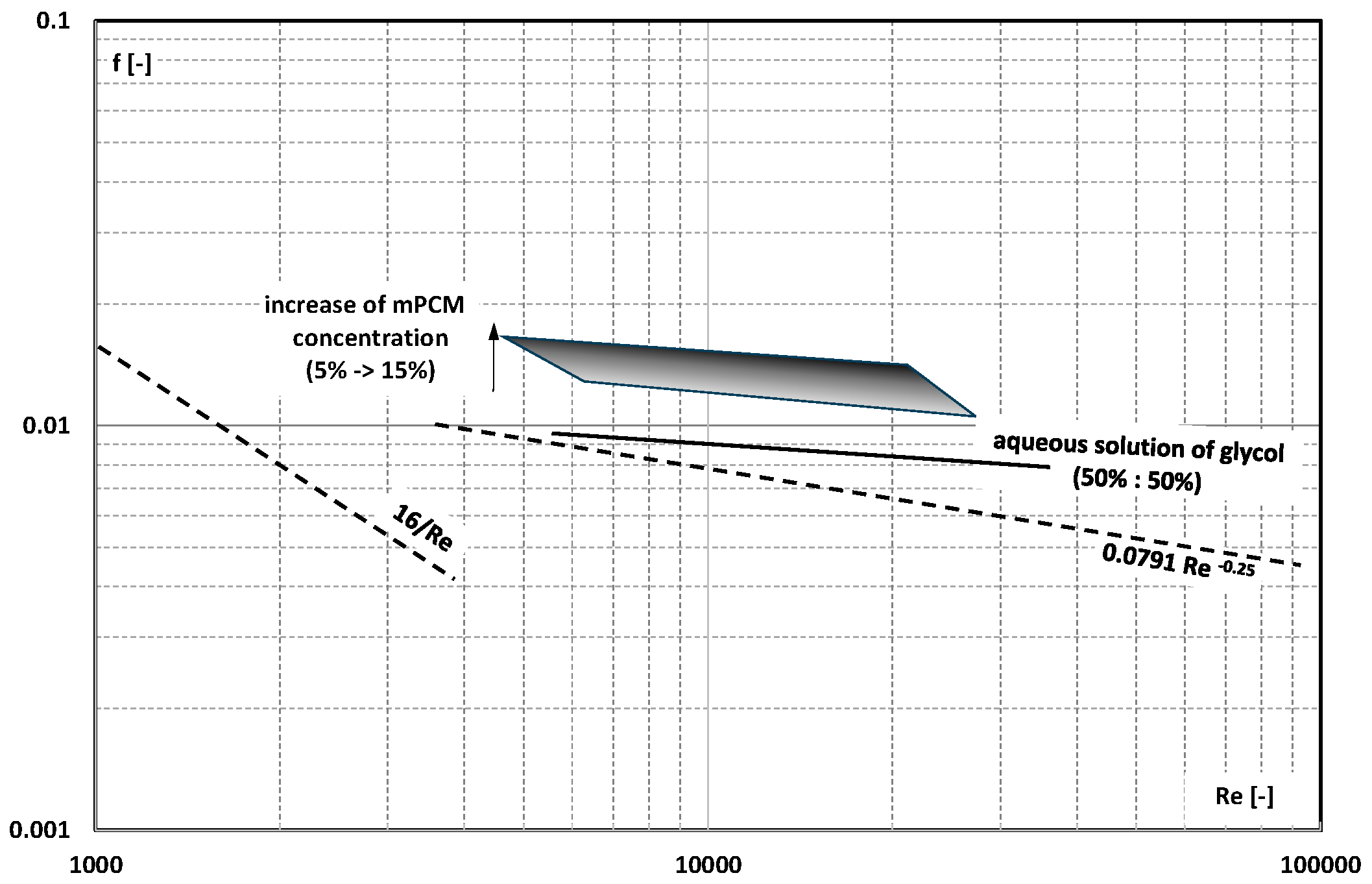
The paper [57] described another slurry. Paraffin with the trade name Rubitherm® RT90HC and a melting point of ~353 K was micro-encapsulated. Particles of mPCM, with an average size of 250 μm, were added to the base liquid in amounts of 5, 7, 10, 12, and 15% by weight. A 1:1 mixture of water and ethylene glycol was used as the base liquid. The mPCM slurry flowed through a pipe L = 1.2 m long and d = 9.53 mm in diameter in the range of Re = 3000–20,000. The Fanning factor calculated on the basis of pressure drop measurements of the mixture of water and ethylene glycol was higher than that following from the Blasius equation but was consistent with the relationship proposed by Swamee-Jain (Figure 25). The friction factor of the slurries was even higher, and the higher the concentration of mPCM, the higher it was.
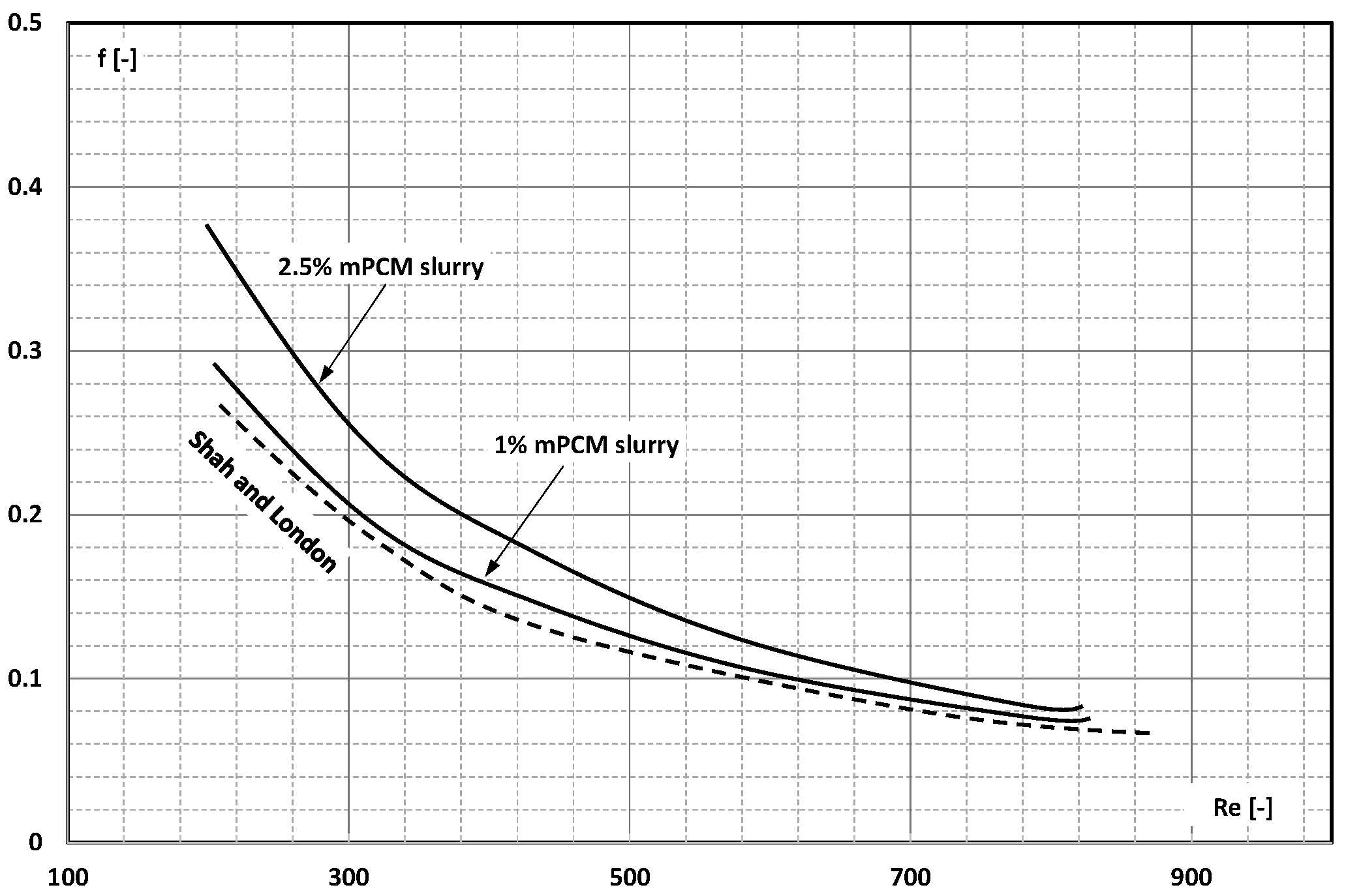
Chen et al. [58] analyzed the effect of the mPCM slurry on heat transfer and pressure drop in copper heat exchangers built on the basis of parallel linear mini-channels and parallel wavy mini-channels. Five mini-channels with a cross-sectional area of 0.5 mm × 0.5 mm were fabricated in a copper block 130 mm long, 28 mm wide, and 7.8 mm thick. The working fluid was a slurry of n-octadecane in a coating of melamine-formaldehyde resin, which was aqueous 1%, 2%, and 2.5% by weight. The mPCM particles had an average diameter of 0.14 μm. The slurry flow was in the laminar range (Re < 900). The results of the friction factor (Figure 26) indicate that the flow of water through corrugated channels was associated with an increase in the value of the friction factor. The value of this coefficient was even higher when water was replaced with mPCM slurry.
The analysis of the data contained in the available publications mentioned above indicates that the friction factor in the laminar flow of the slurry may take values equal to or higher than the value of the coefficient of friction of the base liquid. Neither the diameter of the microcapsule nor the type of coating material or base liquid indicate the cause of the different data. There is agreement that if the concentration of mPCM affects the value of the friction factor, then the ohm is higher with a higher mPCM concentration. The influence of slurry temperature on the friction factor is the inverse. The higher the temperature of the slurry, the lower the friction factor, approaching the friction factor of the base liquid.
In the field of turbulent flow, only a few publications on the friction factor in mPCM slurry flow have been published. Therefore, it should be stated that research in this area is insufficient to draw final conclusions. It was noticed that (depending on the author of the publication) mPCM added to the base liquid may cause an increase in the friction factor, its decrease, or not affect its values at all. It is known that in turbulent flow, the relative roughness of the channel wall has a significant impact on the friction factor. It is expected that subsequent publications will include this fact in the description of the experiment.

4. System Efficiency Improvement Factor/Energy Ratio of Improvement

Slurries of mPCM (nPCM), as clearly demonstrated in experimental studies [59,60,61,62,63,64] and CFD simulations [65,66,67,68,69], are characterized by better effective storage of thermal energy [70,71,72,73] but also by convective heat transfer during the flow of heat-transfer fluid [74,75,76,77,78,79,80,81]. It should be noted, however, that replacing the pure liquid with a slurry with the addition of mPCM improves the heat-transfer coefficient, but it causes an increase in pressure drop. Increased pressure drop means higher pumping power [82,83,84]. Therefore, in the case of mPCM slurries, it is necessary to analyze the results of thermal tests together with flow tests. To assess the possibility of the practical use of mPCM in thermal-flow systems, dimensionless parameters have begun to be used. These parameters are defined in various ways by the authors of the publications: energy ratio of improvement (η), performance evaluation factor (PEF), performance evaluation criterion/coefficient (PEC), or coefficient of performance (COP).
Delgado et al. [85] used the energy ratio of improvement η to assess the profits resulting from the use of mPCM as the working fluid in the heat-transfer system. The ratio was defined as the ratio of the thermal power Q transported by the fluid to the pumping power W for the mPCM slurry and the base liquid, respectively.
η = η   m P C M   s l u r r y η   b a s e   l i q u i d = Q / W   m P C M   s l u r r y Q / W   b a s e   l i q u i d
The energy ratio of improvement was used to evaluate the gains resulting from the use of a 10% aqueous slurry of encapsulated paraffin with a phase-change temperature of 25.5–28 °C for a heat-transfer flow through a pipe length L = 1.82 m and an internal diameter of 10 mm. The test results showed that the use of a 10% aqueous slurry of mPCM (polymer capsules of about 1–20 μm) instead of pure water is thermodynamically justified when the average flow velocity of the slurry is greater than 0.4 m/s (Figure 27). Then, the ratio of the transported thermal energy to the pumping power takes the value η > 1; i.e., despite the increase in pressure drop, the heat-transfer increase was greater than in the case of water.
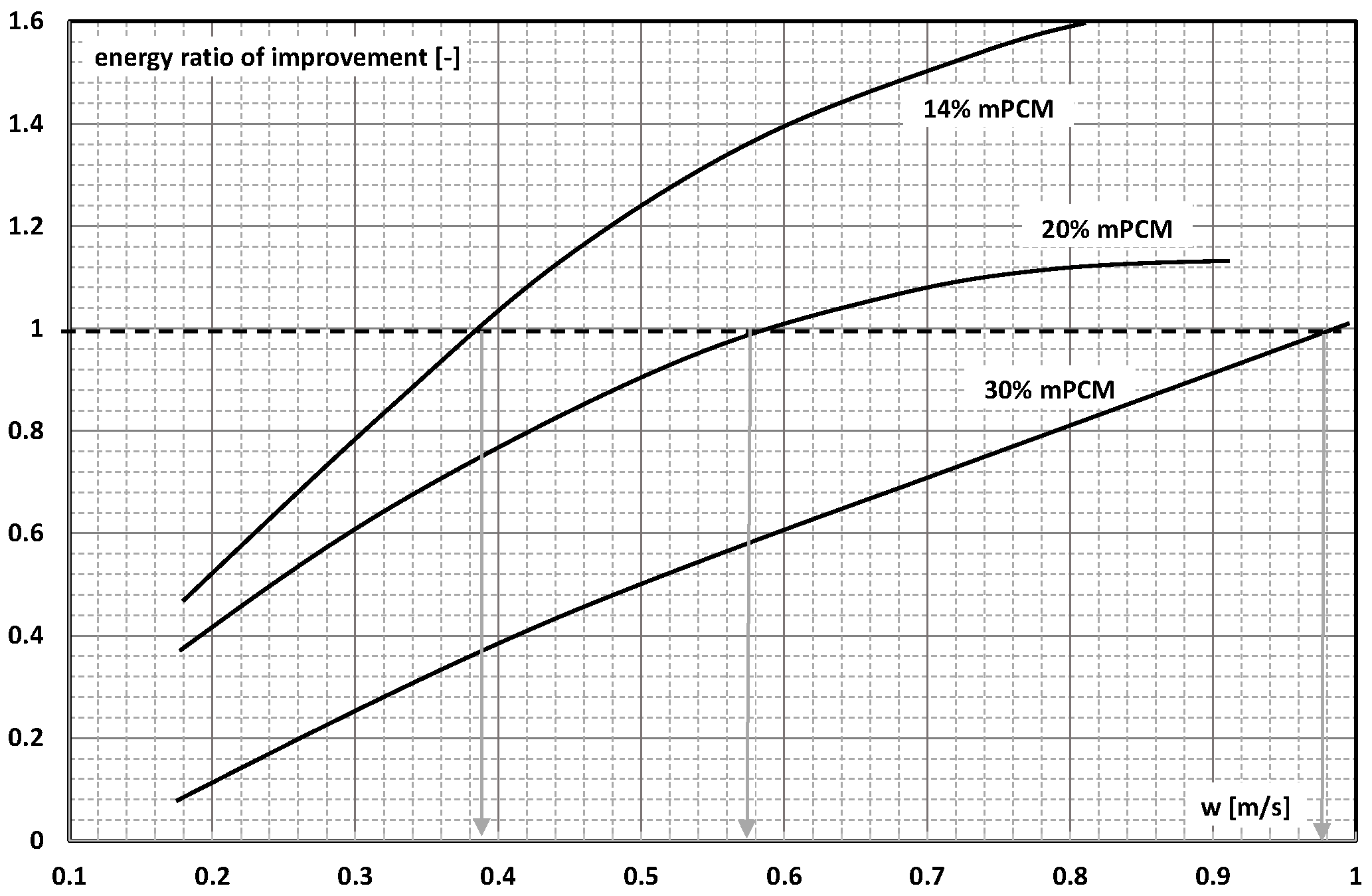
In subsequent studies by the authors of [86], the scope of the experiment was extended to water slurries of mPCM at a concentration of 14%, 20%, and 30%. It was noticed (Figure 28) that when the concentration of mPCM was 14%, the speed of its flow at which the energy ratio of improvement η began to assume a value above unity was 0.6 m/s. For a slurry with a concentration of 20%, it was only 0.4 m/s. Increasing the concentration of the slurry to 30% made the ratio of the transported thermal energy to the pumping power higher than in the case of using water only for the slurry flow velocity above 1 m/s.
Kong et al. published a paper [87] in which they used the performance evaluation criterion (PEC) to assess the benefits of mPCM slurry in thermal-flow processes. This coefficient was defined in the same way as the coefficient of energy improvement η (Formula 8.1). The PEC coefficient was used to evaluate the thermal and flow effects for the mPCM slurry flow. PCM with a melting point of 38.4 °C was encapsulated in a polyurea methyl stearate coating. The mass fraction of mPCM in water was 6%, 6.5%, 8.7%, and 11%. A slurry of particles with an average size of 4.2 μm flowed in the laboratory installation, among others, through a heat exchanger. Figure 29a shows the PEC value for heat transfer in the exchanger during the flow of the mPCM slurry with a mass fraction of 8.7%. It was noticed that regardless of the flow rate of the slurry and despite the increased pressure drop, the PEC index was on average 7% higher than 1. These conclusions are in contradiction with the results presented in the previous work of the authors [88], which showed that a slurry with a concentration of 8.7% has a PEC < 1 regardless of its flow rate, and the correct concentration is 4.6% (Figure 29b).
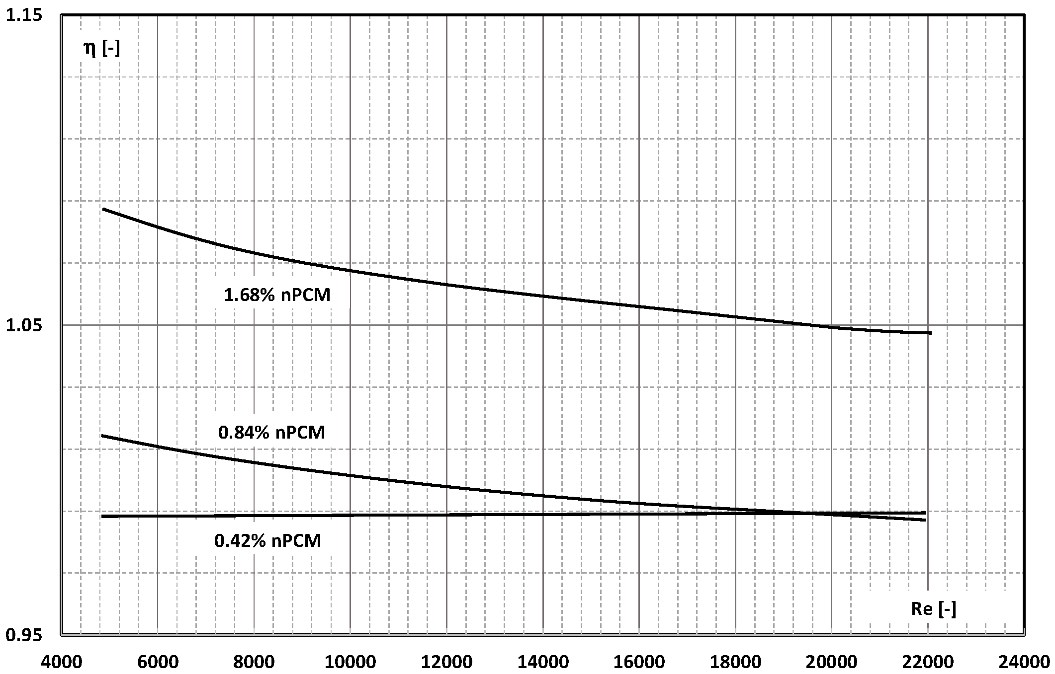
Durok et al. [89] described the results of the study of the pressure drop and heat transfer in a counter-current heat exchanger. The heat exchanger, 1100 mm long, consisted of two coaxially placed pipes made of stainless steel. The inner tube had an inner diameter of 8 mm (1 mm wall thickness), and the outer tube had an inner diameter of 28 mm (2 mm wall thickness). An aqueous slurry of nano-encapsulated PCM flowed inside a smaller diameter pipe. The capsules were made of polyurethane and n-nonadecane as PCM. The average size of the nano capsules was 103 nm. The flow rate of the 0.42%, 0.84%, and 1.68% slurry was changed from 100 L/h to 400 L/h (Re = 5000–20,000). The results of the experimental tests showed (Figure 30) that only in the case of a slurry with a concentration of 1.68% was a significant and approximate 10% increase in the slurry’s heat transfer to base fluid heat-transfer ratio achieved (with the same pumping power).
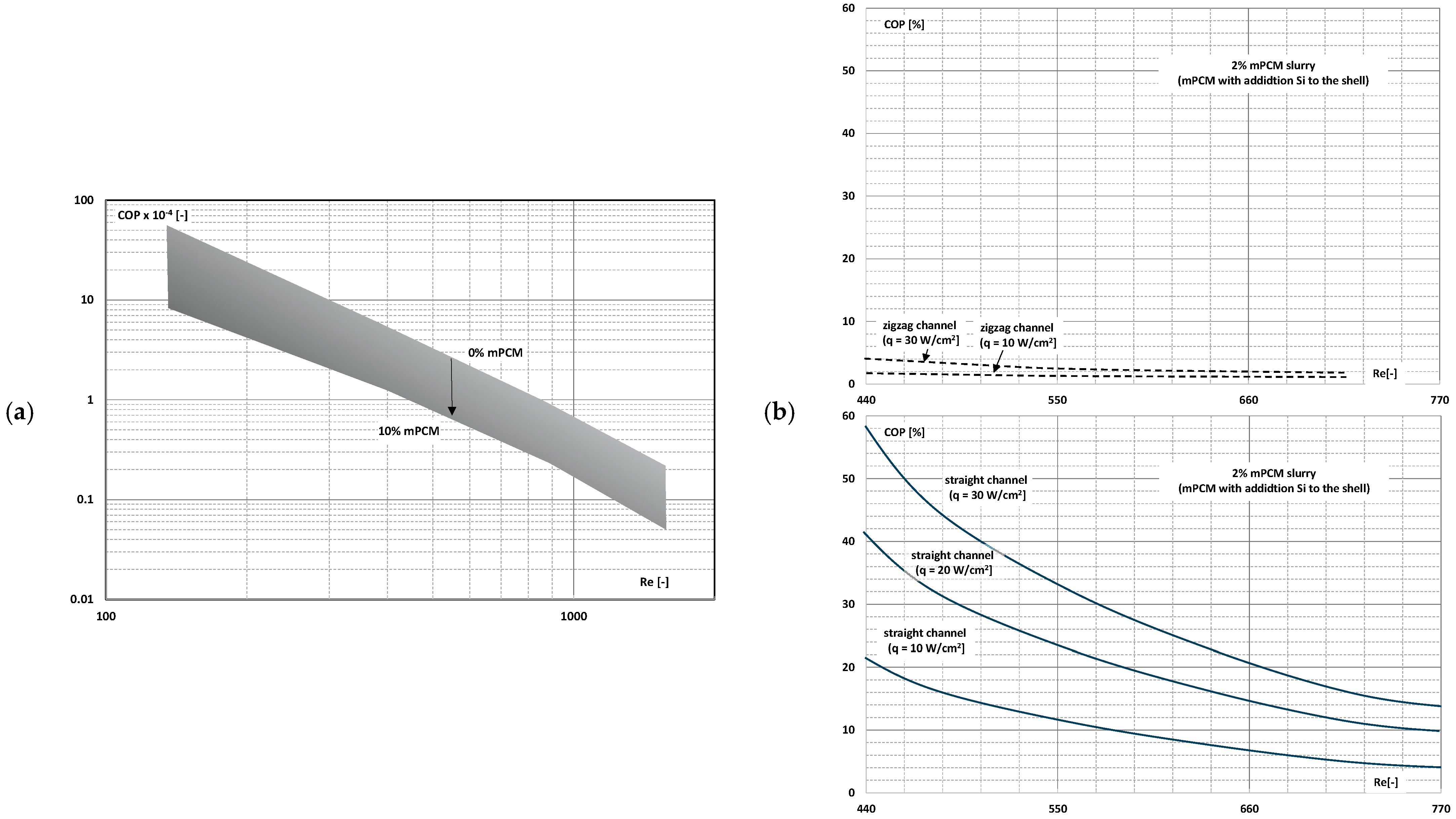
Ho et al. published an article [90] in which the results of the study of the influence of the mPCM slurry on the thermal and flow parameters of the heat sink was described. The heat sink was made of copper and consisted of mini-channels 50 mm long, 1.5 mm deep, and 1 mm wide. mPCM slurry with a concentration of 0 to 10% by weight was used. mPCM flowed through the mini-channels at a speed corresponding to the range of Re = 133–1515. The COP coefficient was defined as the ratio of the thermal power transferred in the exchanger to the slurry-pumping power and was expressed by the following relationship:
C O P = Q W   m P C M   s l u r r y = m ˙ · c p T w · A · p
where m ˙ (kg/s)—slurry mass flow rate; cp (J/(kgK))—slurry specific heat; ΔT (K)—slurry temperature change; w (m/s)—slurry average flow velocity; A (m2)—channel cross-sectional area; Δp (Pa)—slurry pressure drop. Figure 31a shows that the higher the Re number, the proportionally lower the performance evaluation factor. In addition, this coefficient was smaller the higher the concentration of mPCM. Similar conclusions were drawn by the authors of papers [45,46]. However, it was found that the rate of COP decrease was lower with higher Re numbers (Figure 31b), and moreover, the rate of COP decrease was greater in the case of slurry than in the case of water without the addition of mPCM.
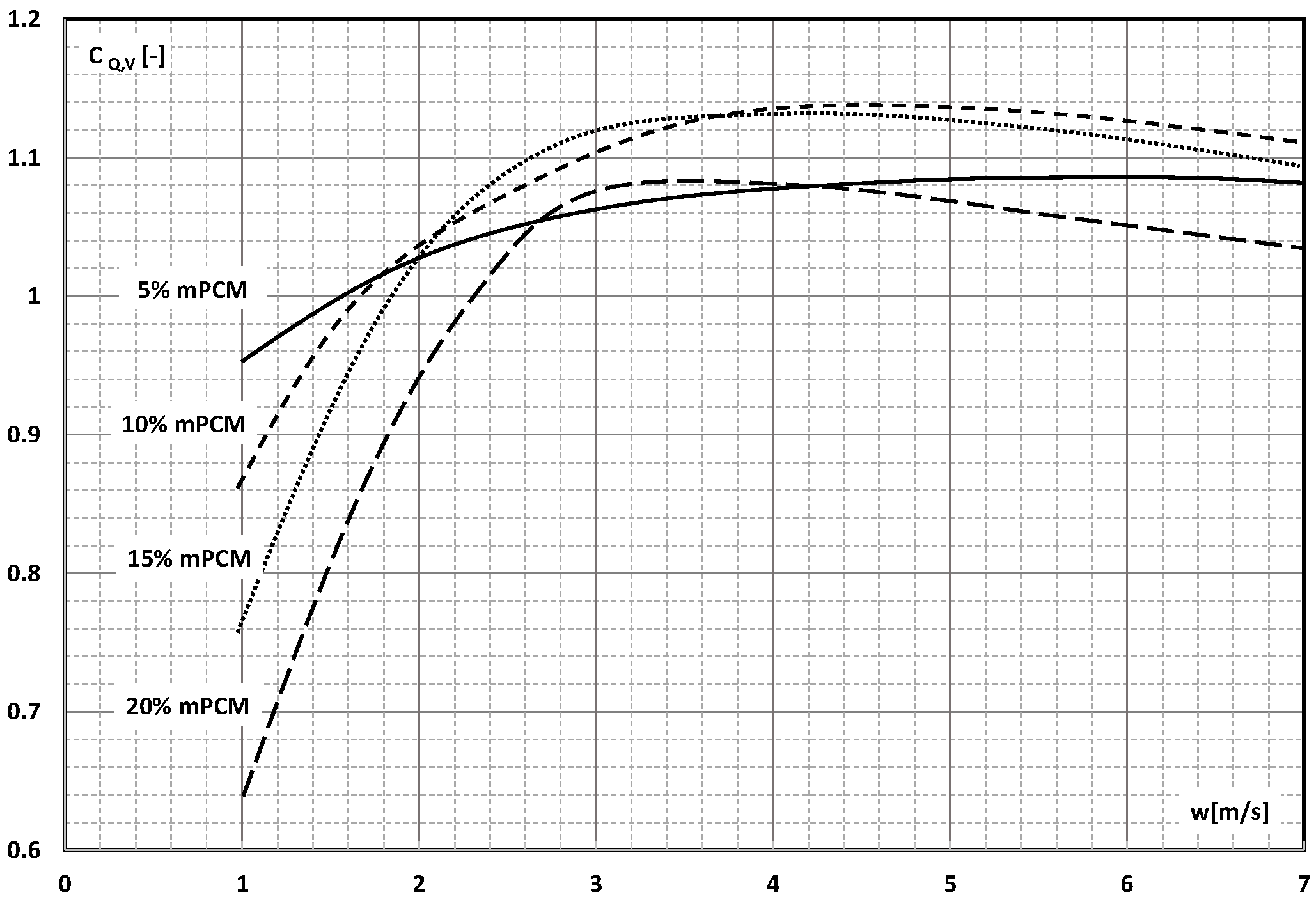
Dai et al. [91] used the comprehensive coefficient of performance CQ,V to evaluate the potential energy gains of using the mPCM slurry as the working fluid flowing through a heat sink with mini-channels inside. The CFD simulation was carried out for one heat sink segment, i.e., a channel 1 mm wide, 10 mm high, and 300 mm long. It was assumed for the simulation that an aqueous slurry of 5–20% by weight flowed through the channel. It was assumed that the mPCM microcapsules had an average size of d = 5 μm and consisted of n-octadecane with a melting point of T = 24 °C and a polymethyl methacrylate (PMMA) shell. Figure 32 shows the value of the complex coefficient of performance CQ,V as a function of the slurry flow rate. The CQ,V coefficient was defined as the ratio of the improvement of heat transfer (Nusselt number—Nu) to the increase in pressure drop (friction factor—f) and was expressed by the following relationship:
C Q , V = N u   m P C M   s l u r r y N u   b a s e   l i q u i d / f   m P C M   s l u r r y f   b a s e   l i q u i d
Figure 32 shows that the value of CQ,V > 1, i.e., the profits resulting from the use of the mPCM slurry for thermal energy transfer, exceed the increase in pressure drop when the slurry flow velocity is greater than 2 m/s for 5%, 10%, and 15% mPCM slurry and greater than 3 m/s for 20% mPCM slurry.
In another study by Dai et al. [92,93], the authors replaced the name of the comprehensive coefficient of performance CQ,V by the performance evaluation factor (PEF) and used it to assess the possibility of using the mPCM slurry in a heat exchanger. The exchanger was a modification of the structure earlier analyzed and additionally had a layer of porous structure on both sides of the channels. The results of the CFD simulation (Figure 33a) allowed the conclusion that the introduction of a porous structure increases the heat-transfer efficiency to a greater extent than the increases in pressure drop. The effect is even better when mPCM slurry is introduced in place of water. At a slurry flow velocity of 3 m/s, PEF increased by 32.3%. When the heat exchanger was equipped with not one but two layers of channels through which the slurry flowed [94], the use of a porous structure improved PEF only in the case of mPCM slurry flow at a speed above 0.3 m/s (Figure 33b). In subsequent studies by this team of authors, the PEF parameter was used to assess the possibility of improving the thermal and flow efficiency of the exchanger modified with wavy, porous “fins” [95] and when the porous layer was deposited on the flat side walls of the channel, and the wavy surfaces comprised the upper and lower canal surface [96]. The ranges of the mPCM slurry flow velocity above which the proposed modifications resulted in an increase in the heat-transfer coefficient greater than the increase in the pressure drop coefficient are shown.
The analysis of the papers contained in this section shows the issues of improving the thermal efficiency of heat-exchange devices by using the mPCM slurries as the working fluid begins to be analyzed in conjunction with the increase in flow resistance. It has been found that the increase in expenditure on pumping the slurry does not always exceed the gains resulting from the increase in transferred thermal energy. It was concluded that the effects resulting from the use of the mPCM slurry in the heat-exchange cycle should be assessed each time. Due to the different methods of heat exchange, there is a lack of research both in the field of free and forced convection in classic ducts (tube channels with a circular cross-section, rectangular, mini-channels, etc.) and with a developed heat-exchange surface.

5. Conclusions and Outlook

This paper provides a comprehensive and chronological review of published flow studies of micro-encapsulated phase-change material (mPCM) and nano-encapsulated phase-change material (nPCM) slurries. It was found that it is possible to use the mPCM (nPCM) slurry as a working fluid circulating in heat-transfer systems. Analysis was performed pertaining to how the adiabatic flow of the mPCM (nPCM) slurry and the flow of the mPCM (nPCM) slurry with heat transfer affect the hydrodynamic parameters of the system operation compared to the flow of liquid without the addition of mPCM (nPCM) and how the knowledge in this area has changed over time. In particular, the focus was on the results of the studies on the pressure drop in the flow of mPCM (nPCM) slurries, the friction factor during the flow of slurries through the channels, and the assessment of whether the thermal gains resulting from the use of encapsulated PCM as an additive to the base liquid exceed the increase in the slurry-pumping power.
The following conclusions can be drawn from the literature review:
  • The number of papers devoted to flow studies of liquids with the addition of mPCM (nPCM) is incomparably smaller than the number of papers devoted to the rheology and heat transfer of these slurries;
  • Occasional experimental studies show the results of measuring the pressure drop during the flow of the mPCM (nPCM) slurry in heat-transfer systems and show that with the increase in the flow velocity of the slurry, the measured pressure drop also increased and was greater the higher the concentration of mPCM (nPCM) in the slurry;
  • There is insufficient information in the literature to determine whether and how the type of PCM, its state of matter, the type and size of the PCM, etc., affect the pressure drop of the flowing slurry;
  • The information contained in previous publications on the friction factor indicates that in the range of laminar and turbulent motion, it may take values lower, equal to, or higher than the value of this coefficient for the base liquid (usually water);
  • There are not enough publications to assess whether and how an increase in the mass fraction of mPCM (nPCM) in the slurry or the matter state of PCM in the capsule affects the value of the friction factor. Current data indicate that it may decrease, increase, or have no effect;
  • The use of mPCM (nPCM) slurry in flow heat-transfer systems is a valid concept because despite the increase in pressure drop, the increase in the heat-transfer coefficient is large enough, provided that the slurry flows fast enough;
  • There are studies that indicate that the higher the slurry flow, after exceeding the limit value, the further the increase in the flow velocity, resulting in another improvement in the efficiency of the exchanger. It stabilizes asymptotically or reaches a certain maximum value, after which it begins to decrease.
The literature review shows that the use of the mPCM slurry in heat-transfer systems makes sense as long as the slurry flows through the heat exchanger fast enough. However, there is a lack of thorough knowledge on how to design/select installation elements even in terms of calculating the pressure drop. This applies to both straight pipeline sections and various types of heat exchangers or elements causing a local pressure drop (valves, elbows, etc.). Further experimental and CFD studies should be carried out that, presented in a dimensionless form, will allow the proposal of correlations for calculating the linear and local friction factor depending on the Re number and slurry concentration, capsule size, type of slurry materials, etc., if this influence is clearly confirmed.
It is proposed to carry out extensive experimental research, the aim of which will be to obtain the characteristics of the pressure drop from the Reynolds number simultaneously in the laminar and turbulent flow of the mPCM slurry. Research in a wide range of Re will allow to determine the friction factor in laminar flow, the critical Reynolds number, and the friction factor in turbulent flow. It is proposed to utilize the Nikuradse plot in order to check whether and to what extent the shape of the previously known characteristics is affected by, for example, the size of the microcapsule, the concentration of mPCM, the state of matter of PCM in the microcapsule, etc. Subsequently, it will be possible to consciously use the existing or proposed new relationships for calculating the friction factor in the mPCM slurry flow in the heat-exchange system. Knowledge of the friction factor is the basis for calculating fluid flow resistance in the installation and, consequently, for selecting a pump forcing the flow.

Funding

This research received no external funding.

Data Availability Statement

Data available upon request due to restrictions, e.g., privacy or ethical.

Conflicts of Interest

The authors declare no conflict of interest.

Nomenclature

AChannel cross-sectional area (m2)
cpSpecific heat (J·kg−1·K−1)
CQ,VComprehensive coefficient of performance (-)
d Diameter (m)
fFriction factor (Fanning factor) (-)
L Length (m)
NuNusselt number (-)
pPressure (Pa)
PECPerformance evaluation criterion (-)
QThermal power (W)
Re Reynolds number (-)
TTemperature (°C)
wVelocity (m·s−1)
WPumping power (W)
Greek letters
ηEnergy ratio of improvement (-)
Abbreviations
mPCMMicro-encapsulated PCM
nPCMNano-encapsulated PCM
PCM Phase-change material

References

  1. Ali, H.M. Phase change materials based thermal energy storage for solar energy systems. J. Build. Eng. 2022, 56, 104731. [Google Scholar] [CrossRef]
  2. Cabaleiro, D.; Agresti, F.; Fedele, L.; Barison, S.; Hermida-Merino, C.; Losada-Barreiro, S.; Bobbo, S.; Piñeiro, M.M. Review on phase change material emulsions for advanced thermal management: Design, characterization and thermal performance. Renew. Sustain. Energy Rev. 2022, 159, 112238. [Google Scholar] [CrossRef]
  3. Qureshi, Z.A.; Ali, H.M.; Khushnood, S. Recent advances on thermal conductivity enhancement of phase change materials for energy storage system: A review. Int. J. Heat Mass Transf. 2018, 127, 838–856. [Google Scholar] [CrossRef]
  4. Khadiran, T.; Hussein, M.Z.; Zainal, Z.; Rusli, R. Encapsulation techniques for organic phase change materials as thermal energy storage medium: A review. Sol. Energy Mater. Sol. Cells 2015, 143, 78–98. [Google Scholar] [CrossRef]
  5. Junaid, M.F.; ur Rehman, Z.; Čekon, M.; Čurpek, J.; Farooq, R.; Cui, H.; Khan, I. Inorganic phase change materials in thermal energy storage: A review on perspectives and technological advances in building applications. Energy Build. 2021, 252, 111443. [Google Scholar] [CrossRef]
  6. Mishra, R.K.; Verma, K.; Mishra, V.; Chaudhary, B. A review on carbon-based phase change materials for thermal energy storage. J. Energy Storage 2022, 50, 104166. [Google Scholar] [CrossRef]
  7. Zhang, H.; Xu, C.; Fang, G. Encapsulation of inorganic phase change thermal storage materials and its effect on thermophysical properties: A review. Sol. Energy Mater. Sol. Cells 2022, 241, 111747. [Google Scholar] [CrossRef]
  8. Li, M.; Mu, B. Effect of different dimensional carbon materials on the properties and application of phase change materials: A review. Appl. Energy 2019, 242, 695–715. [Google Scholar] [CrossRef]
  9. Abdeali, G.; Bahramian, A.R. A comprehensive review on rheological behavior of phase change materials fluids (slurry and emulsion): The way toward energy efficiency. J. Energy Storage 2022, 55, 105549. [Google Scholar] [CrossRef]
  10. Albdour, S.A.; Haddad, Z.; Sharaf, O.Z.; Alazzam, A.; Abu-Nada, E. Micro/nano-encapsulated phase-change materials (ePCMs) for solar photothermal absorption and storage: Fundamentals, recent advances, and future directions. Prog. Energy Combust. Sci. 2022, 93, 101037. [Google Scholar] [CrossRef]
  11. Chai, L.; Shaukat, R.; Wang, L.; Wang, H.S. A review on heat transfer and hydrodynamic characteristics of nano/microencapsulated phase change slurry (N/MPCS) in mini/microchannel heat sinks. Appl. Therm. Eng. 2018, 135, 334–349. [Google Scholar] [CrossRef]
  12. Chen, L.; Wang, T.; Zhao, Y.; Zhang, X.R. Characterization of thermal and hydrodynamic properties for microencapsulated phase change slurry (MPCS). Energy Convers. Manag. 2014, 79, 317–333. [Google Scholar] [CrossRef]
  13. Dutkowski, K.; Fiuk, J.J. Experimental research of viscosity of microencapsulated PCM slurry at the phase change temperature. Int. J. Heat Mass Transf. 2019, 134, 1209–1217. [Google Scholar] [CrossRef]
  14. Dutkowski, K.; Fiuk, J.J. Experimental investigation of the effects of mass fraction and temperature on the viscosity of microencapsulated PCM slurry. Int. J. Heat Mass Transf. 2018, 126, 390–399. [Google Scholar] [CrossRef]
  15. Delgado, M.; Lázaro, A.; Mazo, J.; Zalba, B. Review on phase change material emulsions and microencapsulated phase change material slurries: Materials, heat transfer studies and applications. Renew. Sustain. Energy Rev. 2012, 16, 253–273. [Google Scholar] [CrossRef]
  16. Dutkowski, K.; Kruzel, M.; Zajączkowski, B.; Białko, B. The experimental investigation of mPCM slurries density at phase change temperature. Int. J. Heat Mass Transf. 2020, 159, 120083. [Google Scholar] [CrossRef]
  17. Ghoghaei, M.S.; Mahmoudian, A.; Mohammadi, O.; Shafii, M.B.; Jafari Mosleh, H.; Zandieh, M.; Ahmadi, M.H. A review on the applications of micro-/nano-encapsulated phase change material slurry in heat transfer and thermal storage systems. J. Therm. Anal. Calorim. 2021, 145, 245–268. [Google Scholar] [CrossRef]
  18. Jurkowska, M.; Szczygieł, I. Review on properties of microencapsulated phase change materials slurries (mPCMS). Appl. Therm. Eng. 2016, 98, 365–373. [Google Scholar] [CrossRef]
  19. Liu, L.; Alva, G.; Huang, X.; Fang, G. Preparation, heat transfer and flow properties of microencapsulated phase change materials for thermal energy storage. Renew. Sustain. Energy Rev. 2016, 66, 399–414. [Google Scholar] [CrossRef]
  20. Qiu, Z.; Ma, X.; Li, P.; Zhao, X.; Wright, A. Micro-encapsulated phase change material (MPCM) slurries: Characterization and building applications. Renew. Sustain. Energy Rev. 2017, 77, 246–262. [Google Scholar] [CrossRef]
  21. Ran, F.; Chen, Y.; Cong, R.; Fang, G. Flow and heat transfer characteristics of microencapsulated phase change slurry in thermal energy systems: A review. Renew. Sustain. Energy Rev. 2020, 134, 110101. [Google Scholar] [CrossRef]
  22. Inaba, H. New challenge in advanced thermal energy transportation using functionally thermal fluids. Int. J. Therm. Sci. 2000, 39, 991–1003. [Google Scholar] [CrossRef]
  23. Alvarado, J.L.; Marsh, C.; Sohn, C.; Phetteplace, G.; Newell, T. Thermal performance of microencapsulated phase change material slurry in turbulent flow under constant heat flux. Int. J. Heat Mass Transf. 2007, 50, 1938–1952. [Google Scholar] [CrossRef]
  24. Chen, B.; Wang, X.; Zeng, R.; Zhang, Y.; Wang, X.; Niu, J.; Li, Y.; Di, H. An experimental study of convective heat transfer with microencapsulated phase change material suspension: Laminar flow in a circular tube under constant heat flux. Exp. Therm. Fluid Sci. 2008, 32, 1638–1646. [Google Scholar] [CrossRef]
  25. Dammel, F.; Stephan, P. Heat transfer to suspensions of microencapsulated phase change material flowing through minichannels. J. Heat Transf. 2012, 134, 020907. [Google Scholar] [CrossRef]
  26. Wu, W.; Bostanci, H.; Chow, L.C.; Hong, Y.; Wang, C.M.; Su, M.; Kizito, J.P. Heat transfer enhancement of PAO in microchannel heat exchanger using nano-encapsulated phase change indium particles. Int. J. Heat Mass Transf. 2013, 58, 348–355. [Google Scholar] [CrossRef]
  27. Taherian, H.; Alvarado, J.L.; Tumuluri, K.; Thies, C.; Park, C.H. Fluid flow and heat transfer characteristics of microencapsulated phase change material slurry in turbulent flow. J. Heat Transf. 2014, 136, 061704. [Google Scholar] [CrossRef]
  28. Sinha-Ray, S.; Sinha-Ray, S.; Sriram, H.; Yarin, A.L. Flow of suspensions of carbon nanotubes carrying phase change materials through microchannels and heat transfer enhancement. Lab Chip 2014, 14, 494–508. [Google Scholar] [CrossRef]
  29. Serale, G.; Fabrizio, E.; Perino, M. Design of a low-temperature solar heating system based on a slurry Phase Change Material (PCS). Energy Build. 2015, 106, 44–58. [Google Scholar] [CrossRef]
  30. Qiu, Z.; Ma, X.; Zhao, X.; Li, P.; Ali, S. Experimental investigation of the energy performance of a novel Micro-encapsulated Phase Change Material (MPCM) slurry based PV/T system. Appl. Energy 2016, 165, 260–271. [Google Scholar] [CrossRef]
  31. Wang, Y.; Chen, Z.; Ling, X. An experimental study of the latent functionally thermal fluid with micro-encapsulated phase change material particles flowing in microchannels. Appl. Therm. Eng. 2016, 105, 209–216. [Google Scholar] [CrossRef]
  32. Roberts, N.S.; Al-Shannaq, R.; Kurdi, J.; Al-Muhtaseb, S.A.; Farid, M.M. Efficacy of using slurry of metal-coated microencapsulated PCM for cooling in a micro-channel heat exchanger. Appl. Therm. Eng. 2017, 122, 11–18. [Google Scholar] [CrossRef]
  33. Ho, C.J.; Chang, P.C.; Yan, W.M.; Amani, M. Comparative study on thermal performance of MEPCM suspensions in parallel and divergent minichannel heat sinks. Int. Commun. Heat Mass Transf. 2018, 94, 96–105. [Google Scholar] [CrossRef]
  34. Ho, C.J.; Chang, P.C.; Yan, W.M.; Amani, P. Efficacy of divergent minichannels on cooling performance of heat sinks with water-based MEPCM suspensions. Int. J. Therm. Sci. 2018, 130, 333–346. [Google Scholar] [CrossRef]
  35. Ho, C.J.; Chen, W.C.; Yan, W.M.; Amani, P. Contribution of hybrid Al2O3-water nanofluid and PCM suspension to augment thermal performance of coolant in a minichannel heat sink. Int. J. Heat Mass Transf. 2018, 122, 651–659. [Google Scholar] [CrossRef]
  36. Zhang, G.; Cui, G.; Dou, B.; Wang, Z.; Goula, M.A. An experimental investigation of forced convection heat transfer with novel microencapsulated phase change material slurries in a circular tube under constant heat flux. Energy Convers. Manag. 2018, 171, 699–709. [Google Scholar] [CrossRef]
  37. Zhang, G.; Zhang, B.; Guo, Y.; Cui, G.; Dou, B.; Wang, Z.; Yan, X. Effect of metal oxide particles on the flow and forced convective heat transfer behaviour of microencapsulated PCM slurry. Sol. Energy 2022, 238, 280–290. [Google Scholar] [CrossRef]
  38. Pakrouh, R.; Hosseini, M.J.; Bahrampoury, R.; Ranjbar, A.A.; Borhani, S.M. Cylindrical battery thermal management based on microencapsulated phase change slurry. J. Energy Storage 2021, 40, 102602. [Google Scholar] [CrossRef]
  39. Bai, F.; Chen, M.; Song, W.; Yu, Q.; Li, Y.; Feng, Z.; Ding, Y. Investigation of thermal management for lithium-ion pouch battery module based on phase change slurry and mini channel cooling plate. Energy 2019, 167, 561–574. [Google Scholar] [CrossRef]
  40. Shaukat, R.; Anwar, Z.; Imran, S.; Noor, F.; Qamar, A. Numerical Study of Heat Transfer Characteristics of mPCM Slurry During Freezing. Arab. J. Sci. Eng. 2021, 46, 7977–7988. [Google Scholar] [CrossRef]
  41. Lin, Q.; Wang, S.; Zhang, L. Multi-scale modeling and investigation of thermo-fluidic performance of microencapsulated phase-change material slurry. J. Energy Storage 2021, 37, 102502. [Google Scholar] [CrossRef]
  42. Ashagre, T.B.; Rakshit, D. A study on energy transport performance of Microencapsulated Phase Change Materials (MPCM) slurry. Int. Commun. Heat Mass Transf. 2022, 138, 106321. [Google Scholar] [CrossRef]
  43. Lian, C.; Wang, Y.; Li, Q.; Li, H.; He, X. Numerical investigation on the performance of microencapsulated phase change material suspension applied to liquid cold plates. Numer. Heat Transf. Part A Appl. 2019, 75, 342–358. [Google Scholar] [CrossRef]
  44. Qiu, Z.; Zhao, X.; Li, P.; Zhang, X.; Ali, S.; Tan, J. Theoretical investigation of the energy performance of a novel MPCM (Microencapsulated Phase Change Material) slurry based PV/T module. Energy 2015, 87, 686–698. [Google Scholar] [CrossRef]
  45. Balasubramanian, K.R.; John Peter, R.; B.S, J. Experimental investigation on paraffin encapsulated with Silica and Titanium shell in the straight and re-entrant microchannel heat sinks. Heat Mass Transf. 2023, 59, 1005–1018. [Google Scholar] [CrossRef]
  46. John Peter, R.; Balasubramanian, K.R.; Ravi Kumar, K. Comparative study on the thermal performance of microencapsulated phase change material slurry in tortuous geometry microchannel heat sink. Appl. Therm. Eng. 2023, 218, 119328. [Google Scholar] [CrossRef]
  47. Yamagishi, Y.; Sugeno, T.; Ishige, T. An evolution of microencapsulated PCM for use in cold energy transportation medium. In Proceedings of the 31st Intersociety Energy Conversion Engineering Conference, Washington, DC, USA, 11–16 August 1996; p. 96082. [Google Scholar]
  48. Yamagishi, Y.; Takeuchi, H.; Pyatenko, A.T.; Kayukawa, N. Characteristics of microencapsulated PCM slurry as a heat-transfer fluid. AIChE J. 1999, 45, 696–707. [Google Scholar] [CrossRef]
  49. Inaba, H.; Kim, M.K.; Horibe, A. Melting heat transfer characteristics of microencapsulated phase change material slurries with plural microcapsules having different diameters. J. Heat Transf. 2004, 126, 558–565. [Google Scholar] [CrossRef]
  50. Rao, Y.; Dammel, F.; Stephan, P.; Lin, G. Flow frictional characteristics of microencapsulated phase change material suspensions flowing through rectangular minichannels. Sci. China Ser. E Technol. Sci. 2006, 49, 445–456. [Google Scholar] [CrossRef]
  51. Wang, X.; Niu, J.; Li, Y.; Wang, X.; Chen, B.; Zeng, R.; Song, Q.; Zhang, Y. Flow and heat transfer behaviors of phase change material slurries in a horizontal circular tube. Int. J. Heat Mass Transf. 2007, 50, 2480–2491. [Google Scholar] [CrossRef]
  52. Ho, C.J.; Chen, W.C.; Yan, W.M. Experimental study on cooling performance of minichannel heat sink using water-based MEPCM particles. Int. Commun. Heat Mass Transf. 2013, 48, 67–72. [Google Scholar] [CrossRef]
  53. Ho, C.J.; Chen, W.C.; Yan, W.M. Experiment on thermal performance of water-based suspensions of Al 2O3 nanoparticles and MEPCM particles in a minichannel heat sink. Int. J. Heat Mass Transf. 2014, 69, 276–284. [Google Scholar] [CrossRef]
  54. Cao, F.; Kalinowski, P.; Lawler, J.; Lee, H.S.; Yang, B. Synthesis and heat transfer performance of phase change microcapsule enhanced thermal fluids. J. Heat Transf. 2015, 137, 091018. [Google Scholar] [CrossRef]
  55. Song, S.; Shen, W.; Wang, J.; Wang, S.; Xu, J. Experimental study on laminar convective heat transfer of microencapsulated phase change material slurry using liquid metal with low melting point as carrying fluid. Int. J. Heat Mass Transf. 2014, 73, 21–28. [Google Scholar] [CrossRef]
  56. Li, L.Y.; Zou, D.; Ma, X.F.; Liu, X.S.; Hu, Z.G.; Guo, J.R.; Zhu, Y.Y. Preparation and flow resistance characteristics of novel microcapsule slurries for engine cooling system. Energy Convers. Manag. 2017, 135, 170–177. [Google Scholar] [CrossRef]
  57. Hashimoto, S.; Kurazono, K.; Yamauchi, T. Thermal–hydraulic characteristics of ethylene glycol aqueous solutions containing microencapsulated paraffin. Exp. Therm. Fluid Sci. 2018, 99, 297–303. [Google Scholar] [CrossRef]
  58. Chen, M.; Wang, Y.; Liu, Z. Experimental study on micro-encapsulated phase change material slurry flowing in straight and wavy microchannels. Appl. Therm. Eng. 2021, 190, 116841. [Google Scholar] [CrossRef]
  59. Jadal, M.; Soto, J.; Boyard, N.; Delaunay, D. Experimental determination of crystallization kinetic model of CENG-PCM composite material. Validation at macro and meso scales. Therm. Sci. Eng. Prog. 2022, 33, 101336. [Google Scholar] [CrossRef]
  60. Ye, J.; Mo, S.; Jia, L.; Chen, Y. Experimental performance of a LED thermal management system with suspended microencapsulated phase change material. Appl. Therm. Eng. 2022, 207, 118155. [Google Scholar] [CrossRef]
  61. Yuan, Z.; Liang, K.; Xue, Y.; Yamada, Y.; Isobe, K.; Horibe, A. Experimental study of evaluation of dynamical utilization of a microencapsulated phase change material slurry based on temperature range matching analysis. Int. Commun. Heat Mass Transf. 2022, 130, 105788. [Google Scholar] [CrossRef]
  62. Zheng, H.; Tian, G.; Zhao, Y.; Xin, X.; Yang, C.; Cao, L.; Ma, Y. Experimental study on the preparation and cool storage performance of a phase change micro-capsule cold storage material. Energy Build. 2022, 262, 111999. [Google Scholar] [CrossRef]
  63. Fischer, L.; Maranda, S.; Stamatiou, A.; von Arx, S.; Worlitschek, J. Experimental investigation on heat transfer with a Phase Change Dispersion. Appl. Therm. Eng. 2019, 147, 61–73. [Google Scholar] [CrossRef]
  64. Shi, C.; Zhang, H.; Xuan, Y. Experimental investigation of thermal properties and moisture buffering performance of composite interior finishing materials under different airflow conditions. Build. Environ. 2019, 160, 106175. [Google Scholar] [CrossRef]
  65. Al-Abidi, A.A.; Bin Mat, S.; Sopian, K.; Sulaiman, M.Y.; Mohammed, A.T. CFD applications for latent heat thermal energy storage: A review. Renew. Sustain. Energy Rev. 2013, 20, 353–363. [Google Scholar] [CrossRef]
  66. Wan, H.; He, G.Q.; Xue, Z.R.; Li, W.Q. Numerical study and experimental verification on spray cooling with nanoencapsulated phase-change material slurry (NPCMS). Int. Commun. Heat Mass Transf. 2021, 123, 105187. [Google Scholar] [CrossRef]
  67. Chananipoor, A.; Azizi, Z.; Raei, B.; Tahmasebi, N. Optimization of the thermal performance of nano-encapsulated phase change material slurry in double pipe heat exchanger: Design of experiments using response surface methodology (RSM). J. Build. Eng. 2021, 34, 101929. [Google Scholar] [CrossRef]
  68. Ghasemi, K.; Mahmud, S.; Tasnim, S. Optimization of microencapsulated phase change material slurry-based porous heat exchanger. J. Energy Storage 2022, 55, 105797. [Google Scholar] [CrossRef]
  69. Wang, D.; Niu, X.; Yan, Y.; Gao, P.; Duan, D. Research on falling film dehumidification performance of microencapsulated phase change materials slurry. Energy Build. 2021, 235, 110750. [Google Scholar] [CrossRef]
  70. Mourad, A.; Aissa, A.; Said, Z.; Younis, O.; Iqbal, M.; Alazzam, A. Recent advances on the applications of phase change materials for solar collectors, practical limitations, and challenges: A critical review. J. Energy Storage 2022, 49, 104186. [Google Scholar] [CrossRef]
  71. Liu, Y.; Zheng, R.; Li, J. High latent heat phase change materials (PCMs) with low melting temperature for thermal management and storage of electronic devices and power batteries: Critical review. Renew. Sustain. Energy Rev. 2022, 168, 112783. [Google Scholar] [CrossRef]
  72. Sharma, M.K. Alternative designs and technological advancements of phase change material integrated photovoltaics: A state-of-the-art review. J. Energy Storage 2022, 48, 104020. [Google Scholar] [CrossRef]
  73. Yu, K.; Liu, Y.; Yang, Y. Review on form-stable inorganic hydrated salt phase change materials: Preparation, characterization and effect on the thermophysical properties. Appl. Energy 2021, 292, 116845. [Google Scholar] [CrossRef]
  74. Jiménez-Vázquez, M.; Ramos, F.J.; Garrido, I.; López-Pedrajas, D.; Rodríguez, J.F.; Carmona, M. Production of thermoregulating slurries constituted by nanocapsules from melamine-formaldehyde containing n-octadecane. J. Energy Storage 2022, 51, 104465. [Google Scholar] [CrossRef]
  75. Ashagre, T.B.; Rakshit, D. Study on flow and heat transfer characteristics of Encapsulated Phase Change Material (EPCM) slurry in Double-Pipe Heat Exchanger. J. Energy Storage 2022, 46, 103931. [Google Scholar] [CrossRef]
  76. Xu, L.; Pu, L.; Angelo, Z.; Zhang, D.; Dai, M.; Zhang, S. An experimental investigation on performance of microencapsulated phase change material slurry in ground heat exchanger. Renew. Energy 2022, 198, 296–305. [Google Scholar] [CrossRef]
  77. Shin, D.H.; Kim, S.; Karng, S.W.; Shin, Y. Development of a new type of PCM thermal capsule transport system. Int. J. Heat Mass Transf. 2022, 183, 122034. [Google Scholar] [CrossRef]
  78. Niu, X.; Xia, R.; Dong, H.; Wang, D.; Duan, D.; Gao, P.; Kosonen, R. Dispersion stability and thermophysical properties of microencapsulated phase change material slurry for liquid desiccant dehumidification. Energy Build. 2021, 240, 110870. [Google Scholar] [CrossRef]
  79. Alehosseini, E.; Jafari, S.M. Nanoencapsulation of phase change materials (PCMs) and their applications in various fields for energy storage and management. Adv. Colloid Interface Sci. 2020, 283, 102226. [Google Scholar] [CrossRef] [PubMed]
  80. Qiu, Z.; Li, L. Experimental and numerical investigation of laminar heat transfer of microencapsulated phase change material slurry (MPCMS) in a circular tube with constant heat flux. Sustain. Cities Soc. 2020, 52, 101786. [Google Scholar] [CrossRef]
  81. Liu, L.; Zhu, C.; Fang, G. Numerical evaluation on the flow and heat transfer characteristics of microencapsulated phase change slurry flowing in a circular tube. Appl. Therm. Eng. 2018, 144, 845–853. [Google Scholar] [CrossRef]
  82. Zhang, P.; Ma, Z.W.; Bai, Z.Y.; Ye, J. Rheological and energy transport characteristics of a phase change material slurry. Energy 2016, 106, 63–72. [Google Scholar] [CrossRef]
  83. Yang, L.; Liu, S.; Zheng, H. A comprehensive review of hydrodynamic mechanisms and heat transfer characteristics for microencapsulated phase change slurry (MPCS) in circular tube. Renew. Sustain. Energy Rev. 2019, 114, 109312. [Google Scholar] [CrossRef]
  84. Chen, J.; Zhang, P. Preparation and characterization of nano-sized phase change emulsions as thermal energy storage and transport media. Appl. Energy 2017, 190, 868–879. [Google Scholar] [CrossRef]
  85. Delgado, M.; Lázaro, A.; Mazo, J.; Marín, J.M.; Zalba, B. Experimental analysis of a microencapsulated PCM slurry as thermal storage system and as heat transfer fluid in laminar flow. Appl. Therm. Eng. 2012, 36, 370–377. [Google Scholar] [CrossRef]
  86. Delgado, M.; Lázaro, A.; Peñalosa, C.; Zalba, B. Experimental analysis of the influence of microcapsule mass fraction on the thermal and rheological behavior of a PCM slurry. Appl. Therm. Eng. 2014, 63, 11–22. [Google Scholar] [CrossRef]
  87. Kong, M.; Alvarado, J.L.; Thies, C.; Morefield, S.; Marsh, C.P. Field evaluation of microencapsulated phase change material slurry in ground source heat pump systems. Energy 2017, 122, 691–700. [Google Scholar] [CrossRef]
  88. Kong, M.S.; Yu, K.; Alvarado, J.L.; Terrell, W. Thermal performance of microencapsulated phase change material slurry in a coil heat exchanger. J. Heat Transf. 2015, 137, 071801. [Google Scholar] [CrossRef]
  89. Doruk, S.; Şara, O.N.; Karaipekli, A.; Yapıcı, S. Heat transfer performance of water and Nanoencapsulated n-nonadecane based Nanofluids in a double pipe heat exchanger. Heat Mass Transf. Und Stoffuebertragung 2017, 53, 3399–3408. [Google Scholar] [CrossRef]
  90. Ho, C.J.; Chen, W.C.; Yan, W.M.; Amani, M. Cooling performance of MEPCM suspensions for heat dissipation intensification in a minichannel heat sink. Int. J. Heat Mass Transf. 2017, 115, 43–49. [Google Scholar] [CrossRef]
  91. Dai, H.; Chen, W. Numerical investigation of heat transfer in the double-layered minichannel with microencapsulated phase change suspension. Int. Commun. Heat Mass Transf. 2020, 119, 104918. [Google Scholar] [CrossRef]
  92. Dai, H.; Chen, W.; Cheng, Q.; Liu, Y.; Dong, X. Analysis of thermo-hydraulic characteristics in the porous-wall microchannel with microencapsulated phase change slurry. Int. J. Heat Mass Transf. 2021, 165, 120634. [Google Scholar] [CrossRef]
  93. Dai, H.; Chen, W.; Dong, X.; Liu, Y.; Cheng, Q. Thermohydraulic performance analysis of graded porous media microchannel with microencapsulated phase change material suspension. Int. J. Heat Mass Transf. 2021, 176, 121459. [Google Scholar] [CrossRef]
  94. Dai, H.; Zhu, C.; Liu, Y. Thermal performance of double-layer porous-microchannel with phase change slurry. Appl. Therm. Eng. 2022, 211, 118457. [Google Scholar] [CrossRef]
  95. Dai, H.; Liu, Y. Entropy generation analysis on thermo-hydraulic characteristics of microencapsulated phase change slurry in wavy microchannel with porous fins. Appl. Therm. Eng. 2022, 219, 119440. [Google Scholar] [CrossRef]
  96. Liu, P.; Chen, W. Thermal-hydraulic characteristics analysis in porous-wall corrugated microchannel with microencapsulated phase change slurry. Int. Commun. Heat Mass Transf. 2022, 138, 106316. [Google Scholar] [CrossRef]
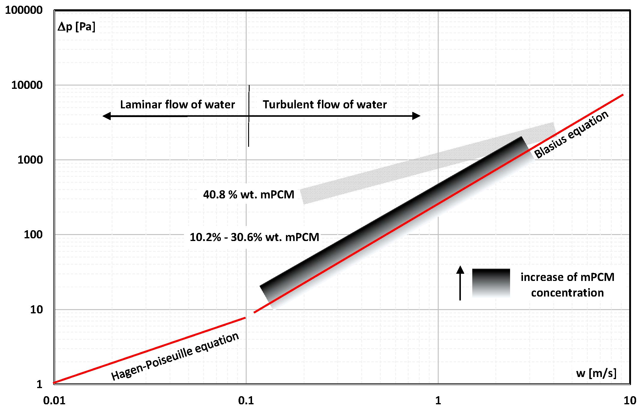
Figure 1. Pressure drop of water and mPCM water slurry in a pipe with a diameter of d = 16 mm and a length of L = 1000 mm vs. flow velocity [22].
Energies 16 06931 g001
Figure 2. Pressure drop in the flow of mPCM slurry with a concentration of 5.9% vs. the flow velocity [23].
Energies 16 06931 g002
Figure 3. The influence of flow velocity on the pressure drop of water and aqueous slurry of mPCM with a concentration of 15.8% at different temperatures (T = 10 °C and T = 20 °C) [24].
Energies 16 06931 g003
Figure 4. The influence of mass flow on the pressure drop of water and slurry of mPCM with a concentration of 10% and 20% [25].
Energies 16 06931 g004
Figure 5. Pressure drop in the flow of PCM oil slurry (PCM with and without encapsulation) in nanochannels with a width of 25 μm and 100 μm from the volume flow rate [26].
Energies 16 06931 g005
Figure 6. Pressure drop in the flow of an aqueous slurry of mPCM based on an innovative material, namely CT041709A (with a concentration of 7% and 11%), and mPCM based on methyl stearate (with a concentration of 5–17%) from the flow velocity [27].
Energies 16 06931 g006
Figure 7. Pressure drop of an aqueous slurry with 3% of nanotubes filled with wax (surfactant concentration 0.7%) and of water according to Hagen–Poiseuille (line) [28].
Energies 16 06931 g007
Figure 8. The influence of mass flow on the pressure drop of water-glycol solution and slurry of mPCM with a concentration of 40% at different times (t = 0 h and after 12 h) [29].
Energies 16 06931 g008
Figure 9. Pressure drop during the flow of 5% mPCM aqueous slurry through the cooling channels of the rear surface of the PV/T panel vs. the Reynolds number [30].
Energies 16 06931 g009
Figure 10. Pressure drop during the flow of 0%, 1% and 2% mPCM water slurry through mini-channels of the heat exchanger vs. the Reynolds number [31].
Energies 16 06931 g010
Figure 11. Pressure drop during the flow of the 5% and 10% mPCM aqueous slurry (with or without the Ag layer on capsule shell) through the mini-channel vs. Re [32].
Energies 16 06931 g011
Figure 12. The influence of Re on the pressure drop of mPCM slurry with a concentration of 0–10% flowing in channels with parallel and divergent (β = 1.38° and β = 2.06°) walls [33].
Energies 16 06931 g012
Figure 13. The influence of water and mPCM slurry (with a concentration 5% and 10%) flow on the pressure drop (a) without metal particles [36]; (b) after adding 1% of metal particles (ZnO or nano ZnO or nano Al2O3) [37].
Energies 16 06931 g013
Figure 14. The influence of (a) flow velocity on the pressure drop of water and aqueous slurry of mPCM with a concentration of 10% and 20% [38]; (b) mPCM volume fraction on slurry pressure drop [43].
Energies 16 06931 g014
Figure 15. Pressure drop of demineralized water; 1% and 2% of mPCM slurry in a coating of silica (Si) and titanium (Ti) from the Reynolds number in a heat sink with (a) straight channel [45]; (b) segmented channel [45]; (c) wavy channel [46].
Energies 16 06931 g015
Figure 16. Friction factor of water flow and mPCM slurry with a concentration of 19.1% and 29.4% and mPCM diameter d = 5 µm vs. the Re number [47].
Energies 16 06931 g016
Figure 17. Fanning factor of laminar and turbulent flow of water and 15% and 30% water slurry of mPCM as a function of Re number [48].
Energies 16 06931 g017
Figure 18. Fanning factor for laminar and turbulent flow slurry of 10%, 20%, 30%, 40%, and 50% mPCM particles with diameter 17 µm in 20% mPCM aqueous slurry (with 1.5 µm mPCM particles size) [49].
Energies 16 06931 g018
Figure 19. The influence of Re on the friction factor of mPCM slurry with a concentration of 5%, 10%, 15%, and 20% [50].
Energies 16 06931 g019
Figure 20. Friction factor for laminar and turbulent flow of mPCM water slurry (concentration of 10%, 15.8%, and 20.4%) vs. Re [51].
Energies 16 06931 g020
Figure 21. Friction factor for laminar flow of mPCM aqueous slurry [52] and mPCM aqueous slurry with 10% Al2O3 nanoparticles [53] on the Re number.
Energies 16 06931 g021
Figure 22. The influence of Re and mPCM slurry temperature (20–35 °C) on the friction factor of 20% mPCM slurry [54].
Energies 16 06931 g022
Figure 23. The influence of Re on the Fanning factor for the laminar flow of the 10–20% slurry (mPCM in liquid metal) vs. the Re number [55].
Energies 16 06931 g023
Figure 24. The influence of Re, slurry’s temperature (79–88 °C), and mPCM concentration (15–25%) on the friction factor [56].
Energies 16 06931 g024
Figure 25. The influence of Re and mPCM concentration (5–15%) on the Fanning factor of aqueous solution of glycol and mPCM slurry [57].
Energies 16 06931 g025
Figure 26. The influence of Re on the friction factor of aqueous slurry of mPCM with a concentration of 1% and 2.5% [58].
Energies 16 06931 g026
Figure 27. The influence of flow velocity on the improvement ratio of aqueous slurry of mPCM with a concentration of 10% [85].
Energies 16 06931 g027
Figure 28. The influence of flow velocity on energy ratio of improvement of 14%, 20%, and 30% aqueous mPCM slurry [86].
Energies 16 06931 g028
Figure 29. The influence of mass flow on the performance evaluation criterion (PEC) of mPCM slurry with a concentration of (a) 8.7% [87]; (b) 4.6% and 8.7% [88].
Energies 16 06931 g029
Figure 30. The influence of Re on the energy ratio of improvement of nPCM slurry with a concentration of 0.42%, 0.84%, and 1.68% [89].
Energies 16 06931 g030
Figure 31. The influence of Re and mPCM concentration on the coefficient of performance (COP) of mPCM slurry: (a) mPCM concentration 0–10% [90]; (b) 2% mPCM and addition Si to the shell [45,46].
Energies 16 06931 g031
Figure 32. The influence of flow velocity on the comprehensive coefficient of performance CQ,V of mPCM slurry with a concentration of 5%, 10%, 15%, and 20% [91].
Energies 16 06931 g032
Figure 33. The influence of flow velocity and surface porosity on the performance evaluation factor (PEF) of water and slurry flow in the heat exchanger with (a) channels in one layer [92], (b) channels in a double layer [94].
Energies 16 06931 g033
Disclaimer/Publisher’s Note: The statements, opinions and data contained in all publications are solely those of the individual author(s) and contributor(s) and not of MDPI and/or the editor(s). MDPI and/or the editor(s) disclaim responsibility for any injury to people or property resulting from any ideas, methods, instructions or products referred to in the content.