Article

Linear Quadratic Gaussian Control of a 6-DOF Aircraft Landing Gear

by
Chimezirim Miracle Nkemdirim
1,
Mohamad Alzayed
1,* and
Hicham Chaoui
1,2,*
1
Intelligent Robotic and Energy Systems Research Group, Faculty of Engineering and Design, Carleton University, Ottawa, ON K1S 5B6, Canada
2
Department of Electrical and Computer Engineering, Texas Tech University, Lubbock, TX 79409, USA
*
Authors to whom correspondence should be addressed.
Energies 2023, 16(19), 6902; https://doi.org/10.3390/en16196902
Submission received: 30 August 2023 / Revised: 27 September 2023 / Accepted: 29 September 2023 / Published: 30 September 2023

Abstract

:
The suspension system of the aircraft, provided by the landing gear, is a crucial part of landing, take-off, and taxiing. It is important that this suspension system not only adequately supports the airframe of the aircraft but also provides a comfortable, seamless ride for the passengers. However, the landing gear is usually riddled with issues, such as landing vibrations that affect passenger comfort and cause damage to the aircraft’s airframe. To reduce these vibrations, this paper proposes the use of a Linear Quadratic Gaussian (LQG) controller to control a 6-DOF aircraft landing gear. The LQG controller is an optimal controller that combines the Linear Quadratic Regulator (LQR) controller with the Kalman filter to compute the system’s control signals and estimate the system’s states. In this paper, the state space model of the 6-DOF landing gear is derived, and the mathematical model of the LQG controller is calculated. The controller’s performance is then tested via MATLAB/Simulink and compared with an equally simple control strategy, the PID controller. The results obtained from the testing process indicate that the LQG controller surpasses the PID controller in reducing landing vibrations, maintaining the aircraft’s airframe, and providing passenger comfort.

1. Introduction

Aircraft landing gear is a critical subsystem of the aircraft, as it provides a suspension system for landing, take-off, and taxiing. The landing gear also plays an important role in providing passenger comfort and ensuring a smooth and seamless landing and take-off. It does this by absorbing and reducing the transmitted vibrations and kinetic energy of the landing impact [1]. However, designing a high-performance landing gear resistant to uncertainties and landing vibrations is a challenge that engineers continue to face. An aircraft landing gear system must be able to reduce the vibrations and kinetic energy that result from the landing impact of an aircraft over an uneven runway surface. It must also provide passenger comfort and reduce the fatigue of the aircraft’s airframe [1]. Ideally, an aircraft landing gear should follow its desired path regardless of landing vibrations or uncertain disturbances (e.g., an uneven runway or parametric variations). Landing gears can be classified into three types: passive, semi-active, and active landing gear [2]. Passive landing gear systems are incapable of adjusting their landing performance or parameters. They obtain optimization only once, and the aircraft technicians are tasked with constantly checking the landing gear to make sure it is in good condition [2]. Semi-active landing gear systems are equipped with dampers, and they achieve control by adjusting the behavior of the viscous friction of the dampers. Active landing gear systems usually have an electrohydraulic damping system capable of producing the external force needed to control landing vibrations and improve the overall quality and performance of the landing gear instantaneously [2]. Generally, passive landing gear systems have a rigid damping system, while active landing gear systems have a more flexible damping system. The first active landing gear system was proposed by Irving Ross and Ralph Edson in 1982 [3]. Since then, there has been a growing interest in the application and control of active landing gear systems. While passive and semi-active control systems have their advantages, this paper will focus on active landing gear systems, as various studies, including [4,5,6,7,
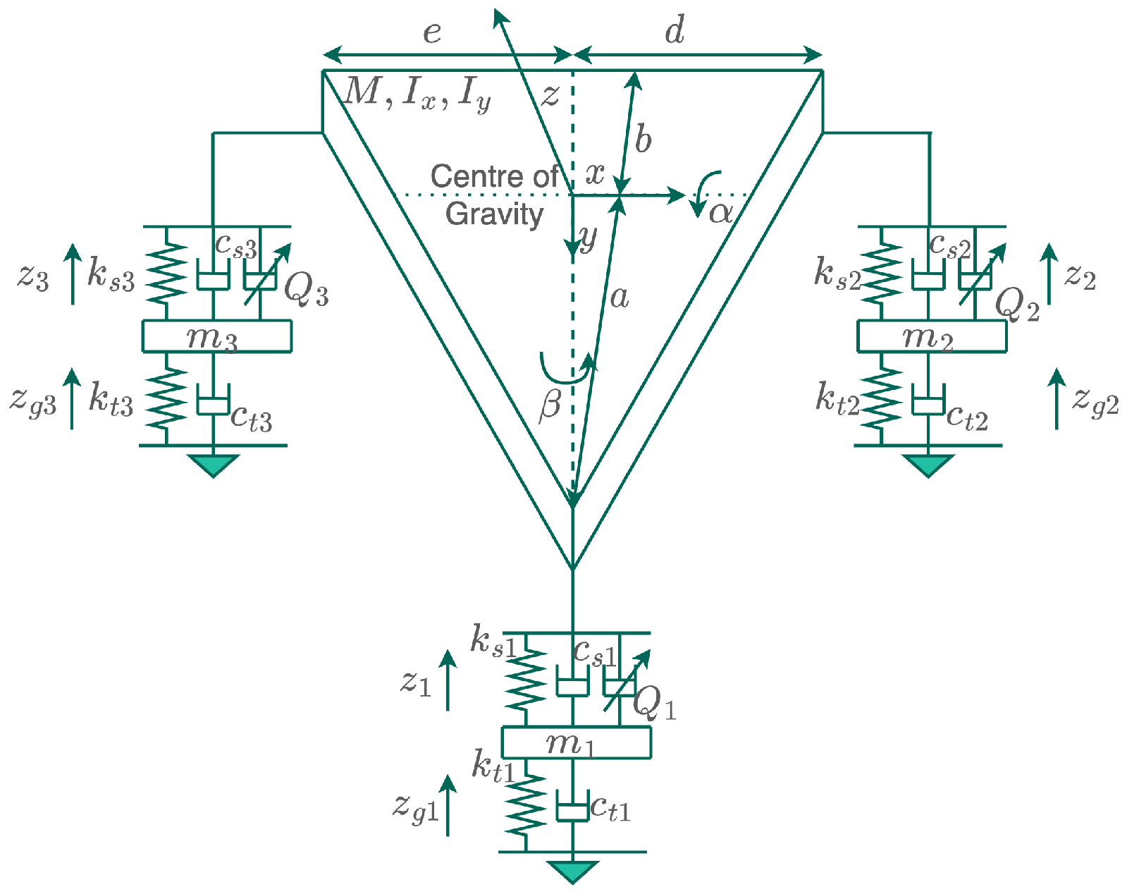
8], have shown that active landing gear systems are experimentally better when it comes to reducing aircraft landing vibrations. The active landing gear system in this paper has six degrees of freedom that dictate the system’s motion. These degrees of freedom are the aircraft’s bounce motion, z, the aircraft’s pitch motion, α , the aircraft’s roll motion, β , the vertical displacement of the aircraft’s nose, z 1 , the vertical displacement of the aircraft’s left main landing gear, z 2 , and the vertical displacement of the aircraft’s right main landing gear, z 3 .
Alongside the various studies on the dynamics of the landing gear system, like the one carried out in [9], there has also been various research on the control of active landing gear systems. In [10], the authors proposed the active control of a landing gear system using a PID controller, and they tuned the controller’s coefficient using the Ziegler–Nichols tuning method. However, the authors were faced with the issue of insufficient parameters needed to deal with overshooting, settling time, etc. These made the PID control too weak to control the system in the presence of larger uncertainties. Similarly, ref. [11] proposed the use of the PID controller of optimization to control a landing gear system. Other research in [12,13] also made use of PID control for an active landing gear system, but in this case, the authors used the Bees Intelligent Algorithm as the optimization technique for modeling the landing gear system.
Ref. [14] proposed an impedance fuzzy control of the active landing gear system. This fuzzy control had three interior loops that controlled the force, body, and position of the aircraft. The inner loop was responsible for controlling the actuator force by a PI controller, the middle loop used a PD-like fuzzy controller to control the position of the aircraft’s body, and the outer loop was the impedance control loop. However, this control strategy lacked the robustness needed to control the landing gear system in the presence of uncertainties. In [15], a landing gear system with an oleo-pneumatic shock absorber was also controlled using the fuzzy control strategy. However, the authors completely ignored the effect of signal and measurement delays in their simulation, thereby limiting the abilities of the control strategy. The authors in [2] proposed the use of a robust nonlinear control system to control an active landing gear. The control system has two interior loops for displacement and force control, and the Lyapunov direct method is used for the asymptotic stability analysis of the control strategy. However, this research work is unnecessarily complex and, as a result, slows down the system. By using a hydraulic supply controlled electronically by servo valves, the authors in [16] controlled a Navy A-6 intruder landing gear. A mechanical admittance approach with two loops was developed in [17] to control a 6-DOF active landing gear system. One loop generated an appropriate trajectory path for the aircraft’s body displacement, and the other loop used PD control to track the generated trajectory. In [1], a Linear Quadratic Regulator (LQR) technique was proposed for the control of an active landing gear system. As a PI-based optimal control technique, the LQR control strategy provided practical feedback gains for the system. However, their research falls short of adequately testing the performance of the controller under various uncertainties and disturbances. The LQR control technique was also combined with an H controller to create a magnetorheological damper in [18]. However, since this design was for semi-active control of a landing gear system, it falls short of efficiently minimizing landing vibrations.
Unlike the existing literature, this paper aims at controlling a 6-DOF aircraft landing gear by combining the LQR control technique with a Kalman filter to propose the Linear Quadratic Gaussian (LQG) control technique. By doing that, this paper presents a novel and innovative approach, as this is one of the first attempts at applying an LQG controller on the 6-DOF aircraft landing gear system. By leveraging the LQG controller’s estimating control abilities, this paper not only optimizes the system’s control but also estimates uncertain variables, resulting in improved landing impact, passenger comfort, and aircraft handling. The research work in this paper represents a significant advancement in the field of aircraft control, providing a more robust and comprehensive approach to the control of landing gear systems. The rest of this paper is organized as follows. Section 2 describes the mathematical and the state space model of the 6-DOF aircraft landing gear, and in Section 3, the mathematical model of the optimal control strategy is outlined. The performance of the LQG controller on the 6-DOF aircraft landing is tested, and the results are discussed in Section 4. The authors’ concluding remarks and suggestions for future works are contained in Section 5.

2. System Model

2.1. Mathematical Model

The schematic diagram of the active landing gear system is shown in Figure 1. The system’s components include a servo actuator, a hydraulic pump, a high-power accumulator, a transducer, an electronic controller, and a low-pressure reservoir [10]. Depending on the landing gear’s landing impact, the electronic controllers receive a signal from the transducer to activate the servo system to supply the landing gears with hydraulic oil. This is done to reduce the vibrations from the landing impact, improve passenger comfort, and maintain the aircraft’s airframe [10]. In the aircraft model used for the landing gear, the fuselage of the aircraft freely moves around the pitch and roll angles. The fuselage is also the sprung mass and attached to it are three unsprung masses, as shown in Figure 2. These three unsprung masses are the front, rear left, and rear right landing gears, which are free to move vertically with respect to the sprung mass. As such, the 6-DOF aircraft model has six degrees of freedom, which include the following:
  • the aircraft’s bounce motion, represented by z;
  • the aircraft’s pitch motion, represented by α ;
  • the aircraft’s roll motion, represented by β ;
  • the vertical displacement of the aircraft’s nose landing gear, represented by z 1 ;
  • the vertical displacement of the aircraft’s left main landing gear, represented by z 2 ;
  • the vertical displacement of the aircraft’s right main landing gear, represented by z 3 [10].
Figure 1. Illustration of an operational landing gear system in which HP denotes high pressure and LP represents low pressure [10].
Energies 16 06902 g001
The aircraft’s bounce, pitch, and roll motions are for the landing gear’s sprung mass, while the vertical displacement of the aircraft’s nose, left main, and right main landing gear are for the landing gear’s unsprung mass. In the mathematical model of the landing gear shown in Figure 2, a represents the distance from the center of gravity (CG) to the nose landing gear, b represents the distance from the CG to the main landing gears, d represents the distance from the CG to the left main landing gear, and e represents the distance from the CG to the right main landing gear [10]. The vibration model of the 6-DOF landing gear consists of a series of spring–mass–damper systems; as such, Newton’s second law of motion can be applied to the six degrees of freedom to obtain the differential equation governing the dynamics of the landing gear system. Hence, the differential equations describing the landing gear system’s dynamics are derived by applying Newton’s second law to the system’s components. The process involves creating a mathematical model diagram, considering forces and accelerations, and possibly linearizing the equations for analysis. Assumptions and simplifications are clarified, and the significance of the derived equations is summarized.
Figure 2. Mathematical model of a 6-DOF aircraft landing gear [10].
Energies 16 06902 g002
Applying Newton’s second law of motion to the aircraft landing gear, the bounce motion of the aircraft’s sprung mass becomes
M z ¨ + c s 1 p ˙ + c s 2 q ˙ + c s 3 r ˙ + k s 1 p + k s 2 q + k s 3 r + Q 1 = 0 ,
where
p = z a α h β z 1
q = z + b α d β z 2
r = z + b α + e β z 3
h = d e
Inserting Equation (2a–d) into Equation (1), the bounce motion of the aircraft’s sprung mass becomes [10]
M z ¨ + c s 1 ( z ˙ a α ˙ h β ˙ z 1 ˙ ) + c s 2 ( z ˙ + b α ˙ d β ˙ z 2 ˙ ) + c s 3 ( z ˙ + b α ˙ + e β ˙ z 3 ˙ ) + k s 1 ( z a α h β z 1 ) + k s 2 ( z + b α d β z 2 ) + k s 3 ( z + b α + e β z 3 ) + Q 1 = 0
The pitch motion of the aircraft’s sprung mass becomes [10]
I y y α ¨ c s 1 p ˙ a + c s 2 q ˙ b + c s 3 r ˙ b k s 1 p a + k s 2 q b + k s 3 r b + Q 2 = 0
and when expanded,
I y y α ¨ c s 1 ( z ˙ a α ˙ h β ˙ z 1 ˙ ) a + c s 2 ( z ˙ + b α ˙ d β ˙ z 2 ˙ ) b + c s 3 ( z ˙ + b α ˙ + e β ˙ z 3 ˙ ) b k s 1 ( z a α h β z 1 ) a + k s 2 ( z + b α d β z 2 ) b + k s 3 ( z + b α + e β z 3 ) b + Q 2 = 0
The roll motion of the aircraft’s sprung mass becomes [10]
I x x β ¨ c s 1 p ˙ h c s 2 q ˙ d + c s 3 r ˙ e k s 1 p h + k s 2 q d + k s 3 r e + Q 3 = 0
and when expanded,
I x x β ¨ c s 1 ( z ˙ a α ˙ h β ˙ z 1 ˙ ) h c s 2 ( z ˙ + b α ˙ d β ˙ z 2 ˙ ) d + c s 3 ( z ˙ + b α ˙ + e β ˙ z 3 ˙ ) e k s 1 ( z a α h β z 1 ) h + k s 2 ( z + b α d β z 2 ) d + k s 3 ( z + b α + e β z 3 ) e + Q 3 = 0
The vertical displacement of the aircraft’s nose landing gear motion, z 1 , which has an unsprung mass, becomes [10]
m 1 z 1 ¨ c s 1 p ˙ k s 1 p + c t 1 ( z ˙ z ˙ g 1 ) + k t 1 ( z 1 z g 1 ) Q 1 = 0
and when expanded,
m 1 z 1 ¨ c s 1 ( z ˙ a α ˙ h β ˙ z 1 ˙ ) k s 1 ( z a α h β z 1 ) h + c t 1 ( z ˙ z ˙ g 1 ) + k t 1 ( z 1 z g 1 ) Q 1 = 0
The vertical displacement of the left main landing gear, z 2 , which has an unsprung mass, becomes [10]
m 2 z 2 ¨ c s 2 q ˙ k s 2 q + c t 2 ( z ˙ z ˙ g 2 ) + k t 1 ( z 2 z g 2 ) Q 2 = 0
and when expanded,
m 2 z 2 ¨ c s 2 ( z ˙ + b α ˙ d β ˙ z 2 ˙ ) k s 1 ( z + b α d β z 2 ) h + c t 2 ( z ˙ z ˙ g 2 ) + k t 1 ( z 2 z g 2 ) Q 2 = 0
The vertical displacement of the right main landing gear, z 3 , which has an unsprung mass, becomes [10]
m 3 z 3 ¨ c s 2 r ˙ k s 2 r + c t 3 ( z ˙ z ˙ g 3 ) + k t 1 ( z 3 z g 3 ) Q 3 = 0
and when expanded,
m 3 z 3 ¨ c s 3 ( z ˙ + b α ˙ + e β ˙ z 3 ˙ ) k s 3 ( z + b α e β z 3 ) h + c t 3 ( z ˙ z ˙ g 3 ) + k t 1 ( z 3 z g 3 ) Q 3 = 0
Equations (3), (5), (7), (9), (11) and (13) are the second-order differential equations that make up the dynamics of the 6-DOF aircraft landing gear. When rewritten, these second-order differential equations become
M Z ¨ + C d Z ˙ + K d Z = F
where M is the mass matrix written as
M = M 0 0 0 0 0 0 I y y 0 0 0 0 0 0 I x x 0 0 0 0 0 0 m 1 0 0 0 0 0 0 m 2 0 0 0 0 0 0 m 3
C d is the damping matrix written as
C d = N 1 N 2 N 3 c s 1 c s 2 c s 3 N 2 N 4 N 5 a c s 1 b c s 2 b c s 3 N 3 N 5 N 6 h c s 1 d c s 2 e c s 3 c s 1 a c s 1 h c s 1 c s 1 + c t 1 0 0 c s 2 b c s 2 d c s 2 0 c s 2 + c t 2 0 c s 3 b c s 2 e c s 3 0 0 c s 3 + c t 3
where
N 1 = c s 1 + c s 2 + c s 3 N 2 = a c s 1 + b c s 2 + b c s 3 N 3 = h c s 1 d c s 2 + e c s 3 N 4 = a 2 c s 1 + b 2 c s 2 + b 2 c s 3 N 5 = h a c s 1 d b c s 2 + e b c s 3 N 6 = h 2 c s 1 + d 2 c s 2 + e 2 c s 3
K d is the stiffness matrix, written as
K d = R 1 R 2 R 3 k s 1 k s 2 k s 3 R 2 R 4 R 5 a k s 1 b k s 2 b k s 3 R 3 R 5 R 6 h k s 1 d k s 2 e k s 3 k s 1 a k s 1 h k s 1 k s 1 + k t 1 0 0 k s 2 b k s 2 d k s 2 0 k s 2 + k t 2 0 k s 3 k c s 2 e k s 3 0 0 k s 3 + k t 3
where
R 1 = k s 1 + k s 2 + k s 3 R 2 = a k s 1 + b k s 2 + b k s 3 R 3 = h k s 1 d k s 2 + e k s 3 R 4 = a 2 k s 1 + b 2 k s 2 + b 2 k s 3 R 5 = h a k s 1 d b k s 2 + e b k s 3 R 6 = h 2 k s 1 + d 2 k s 2 + e 2 k s 3
Z represents the displacement vector of the aircraft landing gear, which consists of the aircraft’s six degrees of freedom. It is written as Z = z α β z 1 z 2 z 3 T and F is the force vector, written as
F = Q 1 Q 2 Q 3 k t 1 u g 1 + c t 1 u ˙ g 1 + Q 1 k t 2 u g 2 + c t 2 u ˙ g 2 + Q 2 k t 3 u g 3 + c t 3 u ˙ g 3 + Q 3 = F 1 F 2 F 3 F 4 F 5 F 6

2.2. State Space Model

These differential equations that govern the 6-DOF aircraft landing gear can be represented as standard state equations in the matrix form
X ˙ = A X + B U
Y = C X + D U
Inserting matrices M , C d , K d , Z , and F into Equation (14), 12 state space variables are obtained as follows:
X = Z Z ˙ T
The state space matrix form of the 6-DOF aircraft landing gear can then be written as
X ˙ = 0 6 × 6 I 6 × 6 M 1 K 6 × 6 M 1 C 6 × 6 X + 0 6 × 6 M 6 × 6 1 F
Y = I 6 × 6 0 6 × 6 X
and matrices A , B , C are given as
A = 0 6 × 6 I 6 × 6 M 1 K d 6 × 6 M 1 C d 6 × 6 , B = 0 6 × 6 M 6 × 6 1 , C = I 6 × 6 0 6 × 6

3. Optimal Control Technique

The LQG control technique is an optimal quadratic technique that is composed of the LQR controller and the Kalman filter. These two parts of the LQG controller work together to facilitate both state control and state estimation.

3.1. LQR Controller

The LQR controller is one of the most common feedback control strategies and is designed to solve an optimization problem modeled around control signals [19]. It essentially aims to minimize a cost function, J, using the system’s control signals. The LQR controller is also a linear controller that can be represented as u = K x , where u represents the sequence of control signals, x is the desired state, and K is the feedback gain that will lead us to the desired state [19]. Using the state space model of the 6-DOF aircraft landing gear represented in this form, x ˙ = A x + B u , we can assume the cost function of the landing gear system to be [20]
J ( u ˜ ) = 0 x T Q ˜ x + u T R ˜ u dt
where Q ˜ and R ˜ are both weighting matrices. Q ˜ is a 12 × 12 positive definite matrix, and R ˜ is a 6 × 6 positive definite matrix. Since x represents the desired state, the solution to Equation (24) must satisfy all values of x in Equation (25):
min u [ x T Q ˜ x + u T R ˜ + J * x ( A ˜ x + B ˜ x ) ] = 0
where
A ˜ = A 6 × 6 0 6 × 3 C 3 × 6 0 3 × 3 18 × 18
B ˜ = B 6 × 3 0 3 × 3 18 × 6
This solution can then be presented as
J * ( x ) = x T P ˜ x
with a gradient of
J * x = 2 x T P ˜
where
u = 2 u T R ˜ + 2 x T P ˜ B ˜ = 0
When rearranged, Equation (30) becomes the optimal linear policy [20],
u = R ˜ 1 B ˜ T P ˜ x = K ˜ x
where the feedback gain matrix K ˜ is
K ˜ = R ˜ 1 B ˜ T P ˜
and P ˜ can be calculated using
0 = P ˜ A ˜ + A ˜ T P ˜ P ˜ B ˜ R ˜ 1 B ˜ T P ˜ + Q ˜

3.2. Kalman Filter

The second part of the LQG controller is the Kalman filter. The Kalman filter acts as a state estimator and works to reduce the estimated error covariance of the system [21]. Essentially, it monitors the sequence of control signals and data over time, which are usually riddled with noise and uncertainties, and then it optimally estimates the system’s unknown variables [22]. When the Kalman filter is included in the system, it can be assumed that the standard state form of the system becomes [23]
x ˙ ( t ) = A x ( t ) + B u ( t ) + G w ( t )
y ( t ) = C x ( t ) + D u ( t ) + v ( t )
where Equation (34) is the state and measurement equations of the system, respectively, which together form the Kalman model. Matrices A and B are represented by Equations (26) and (27), and w ( t ) and v ( t ) are the white noise processes. The zero mean and covariance values of the filter are presented as
E [ w ( t ) w ( t + τ ) T ] = Q δ ( τ )
E [ v ( t ) v ( t + τ ) T ] = R δ ( τ )
E [ w ( t ) v ( t + τ ) T ] = 0
As an estimator, the Kalman filter’s goal is to calculate x ^ ( t ) , which is the estimated value of the system’s state, x ( t ) [24]. This estimated output is given by
x ^ ˙ ( t ) = A x ^ ( t ) + B u ( t ) + K f ( y ( t ) C x ^ ( t ) D u )
and the estimation error covariance matrix of the Kalman filter is given by
J = E [ ( x ( t ) x ^ ( t ) ) T ( x ( t ) x ^ ( t ) ) ]
where K f , the Kalman gain, is calculated by
K f = P ( t ) C T R 1
with an error covariance update matrix evaluated by
P ˙ ( t ) = A P ( t ) + P A T + G Q G T P ( t ) C T R 1 C P ( t )
In summary, given the 6-DOF landing gear system, the LQG controller can be implemented on the system using the following steps [25]:
Step 1:
Determine matrices A , B , and C by calculating the parameters of the landing gear system, Equation (23).
Step 2:
Determine the augmented matrices, A ˜ and B ˜ , and give a definition to the two weighting matrices Q ˜ and R ˜ , Equations (26) and (27).
Step 3:
Determine the LQR gain matrix, K ˜ , Equation (32).
Step 4:
Solve for the estimating Kalman filter gain, K f , Equation (38).
Step 5:
Calculate the Kalman filter output value x ^ ( t ) , Equation (36).
Step 6:
Lastly, implement the optimal tracking control system, as shown in Figure 3.

4. Results and Discussion

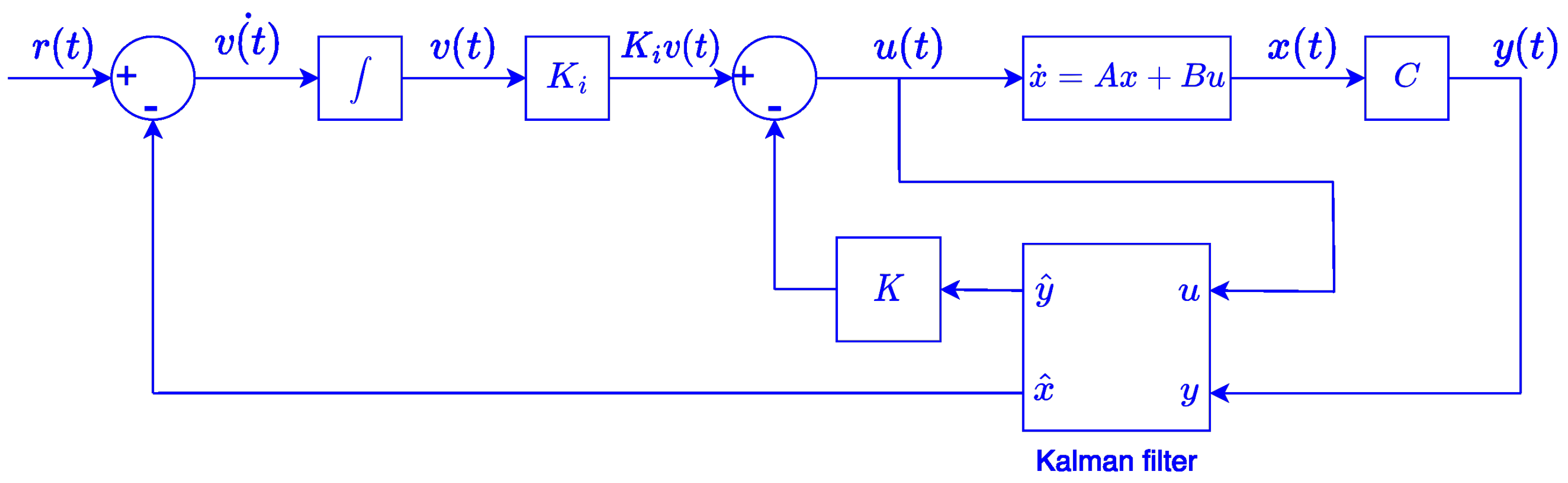
The performance of the LQG controller on the 6-DOF aircraft landing gear is tested and simulated using MATLAB/Simulink. The block diagram of the LQG optimal controller presented in Figure 3 is used as a modeling approach, which describes the used approach to create the simulation model. The presented six steps highlight the LQG controller of the landing gear system implementation, which also breaks down the system into its constituent components and explains how each component is represented in the model. In addition, Section 3, Optimal Control Technique, provides the fundamental equations that govern the behavior of each component in the model. The parameters used to assess the landing gear system are shown in Table 1, and they are obtained from a Fokker aircraft. The goal of applying the controller on the landing gear system is to reduce the landing vibrations of the system and provide passenger comfort on the aircraft despite human-induced or natural disturbances. Therefore, the landing gear has to follow the desired trajectory path as closely as possible, regardless of the uncertainties it faces. For this testing purpose, the desired reference trajectory is a step response of a first-order system with an initial value of 0 and a final value of 1, where t [ 0 , 50 ] s. The system’s response to the reference trajectory is analyzed using the system’s six degrees of freedom, z, α , β , z 1 , z 2 , and z 3 , as well as their tracking errors and control signals.
Firstly, the LQG controller is tested under nonzero initial conditions with a value of 0.5 rad. After the system attains stability from the nonzero initial condition, the z 2 , z 3 , z, α , β , and z 1 
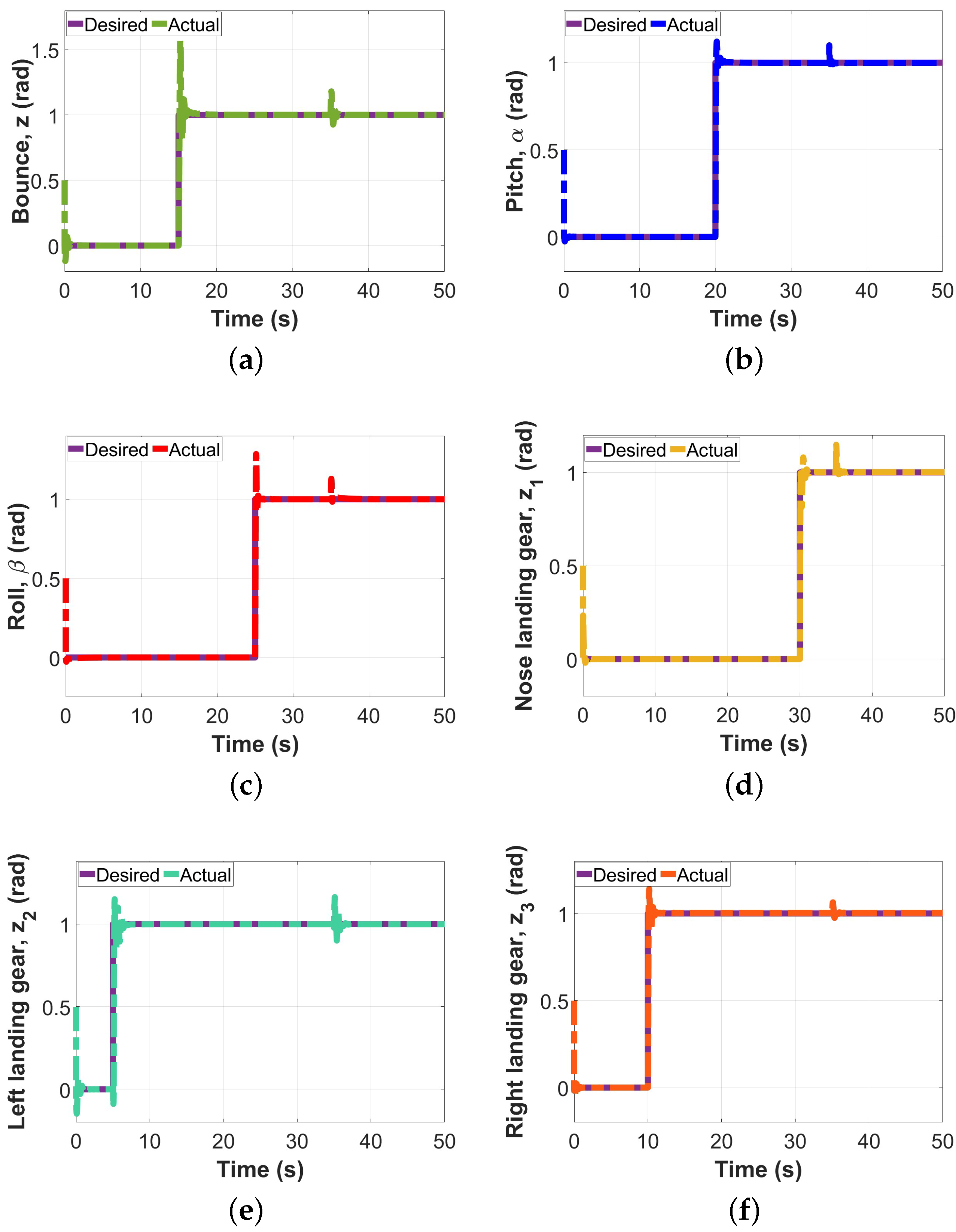
motions are subjected to a step change at 5 s, 10 s, 15 s, 20 s, 25 s, and 30 s, respectively. As unexpected disturbances are a part of the uncertainties that the landing gear is bound to face in the real world, a simulated disturbance at 35 s is also applied to the system to assess the performance of the controller. This disturbance is applied to all six motions. By doing this, the LQG controller’s performance on the landing gear under nonzero initial conditions, nominal scenarios, and unexpected disturbances is assessed. The results obtained from the simulations are shown in Figure 4 and Figure 5. The first three seconds of each graph in 
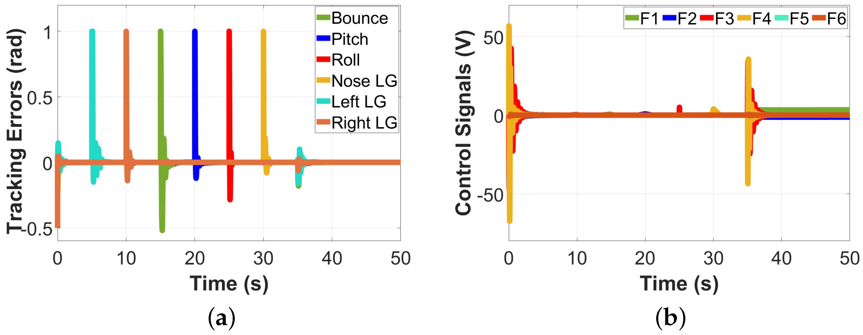
Figure 4 show the system’s response to nonzero initial conditions. From the results, it can be noted that despite the nonzero initial condition, the controller was able to converge to the desired path in very little time, thereby showing that nonzero initial conditions have little to no effect on it. Once the system becomes stable, it continues in the nominal state until 35 s. In this nominal state, the controller follows the desired trajectory path closely and only has a slight overshoot when the step changes occur. However, despite the step changes, the controller is still able to converge the system to its desired path in less than 2 s, thereby maintaining the system’s stability. The controller also performs excellently in the presence of an unexpected disturbance at 35 s, as it has a slight overshoot for less than a second and converges to the desired path. The tracking errors obtained in Figure 5 also show that despite the nonzero initial conditions, the step changes, and uncertain disturbances, the controller is able to decay all errors to zero, maintaining a stable landing gear system. The result of the control signals of the system is shown in Figure 5 with a slight undershoot response to the nonzero initial condition and a slight overshoot at the step changes and unexpected disturbance. However, despite these testing conditions, the controller is successful at bringing the control signal to its desired path.
Since the LQG controller also acts as an estimator through the Kalman filter, the estimation performance of the filter has to be tested as well. As such, the Kalman estimator is assessed under the same testing conditions, and the results are shown in Figure 6. 
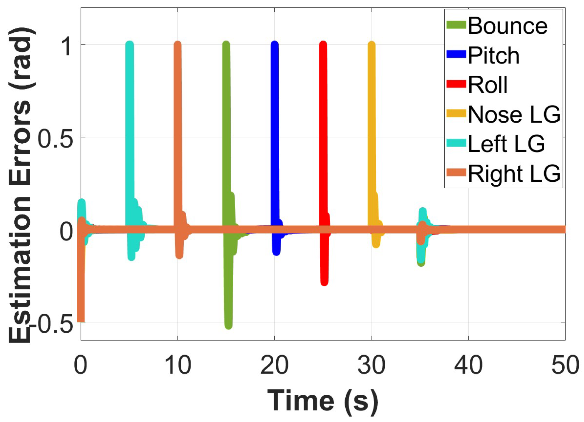
Figure 6 shows the Kalman filter estimate output for all six degrees of freedom. The results show the controller’s estimated response to the testing conditions applied. Despite these testing conditions, the controller optimally estimated the system’s state while following the trajectory path closely. The estimation error is also shown in Figure 7, and the controller does an excellent job of decaying all estimation errors to zero and maintaining the system’s stability. After that, the controller is compared to a PID controller, an equally simple strategy. The PID controller is tested on the landing gear system under the same testing conditions, and the results are shown in Figure 8 and Figure 9.
Just like the LQG controller, the first three seconds show the response of the PID controller under nonzero initial conditions; the nominal case is shown from 5 s to 35 s, and at 35 s, the controller’s response to unexpected disturbances is shown. As can be seen in the results, the PID controller does not follow the trajectory path as closely as the LQG controller does. The PID controller also takes a longer time than the LQG controller to decay its tracking errors to zero. The control signals of the PID controller shown in Figure 9b also do not converge to zero as easily as those of the LQG controller.
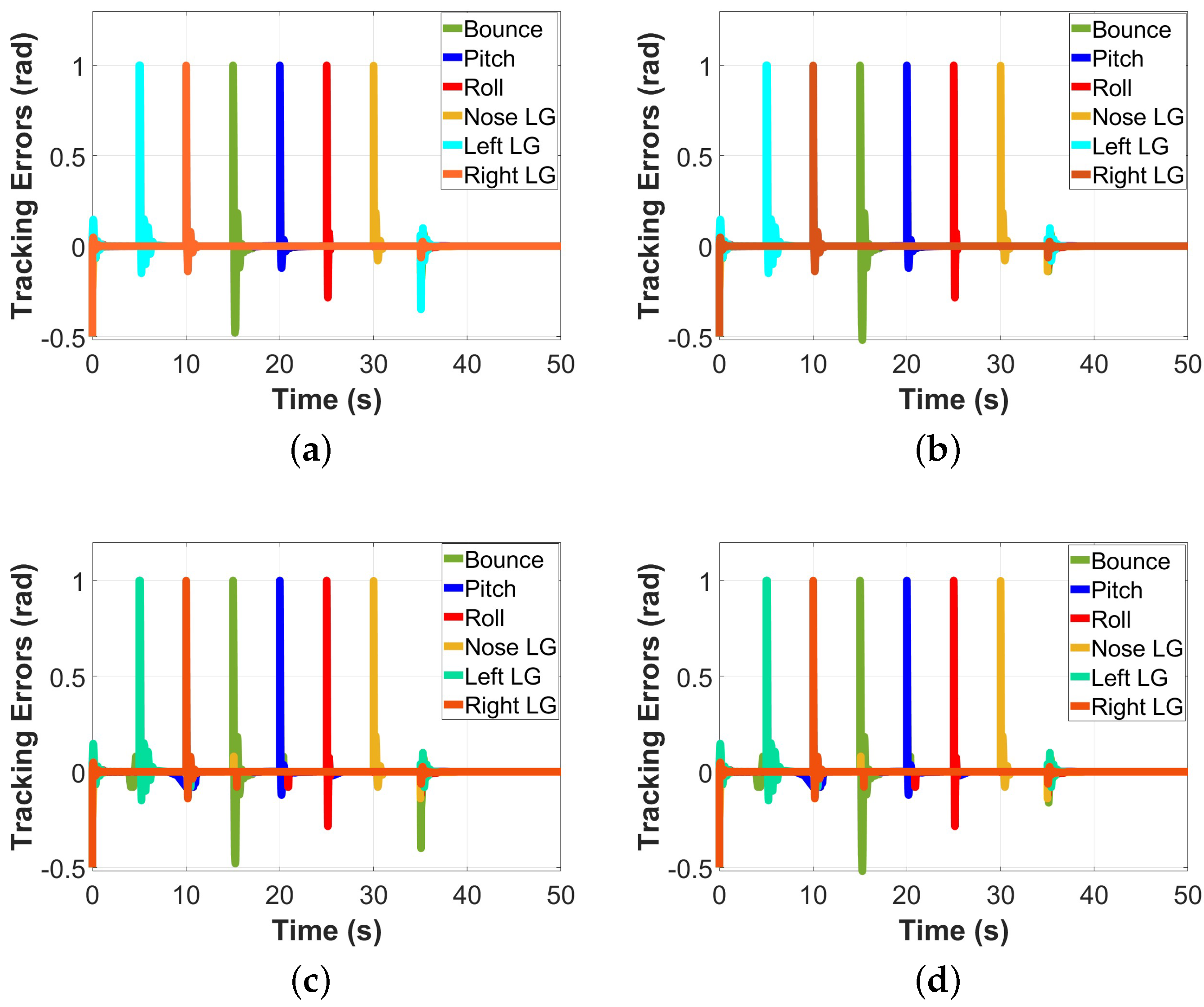
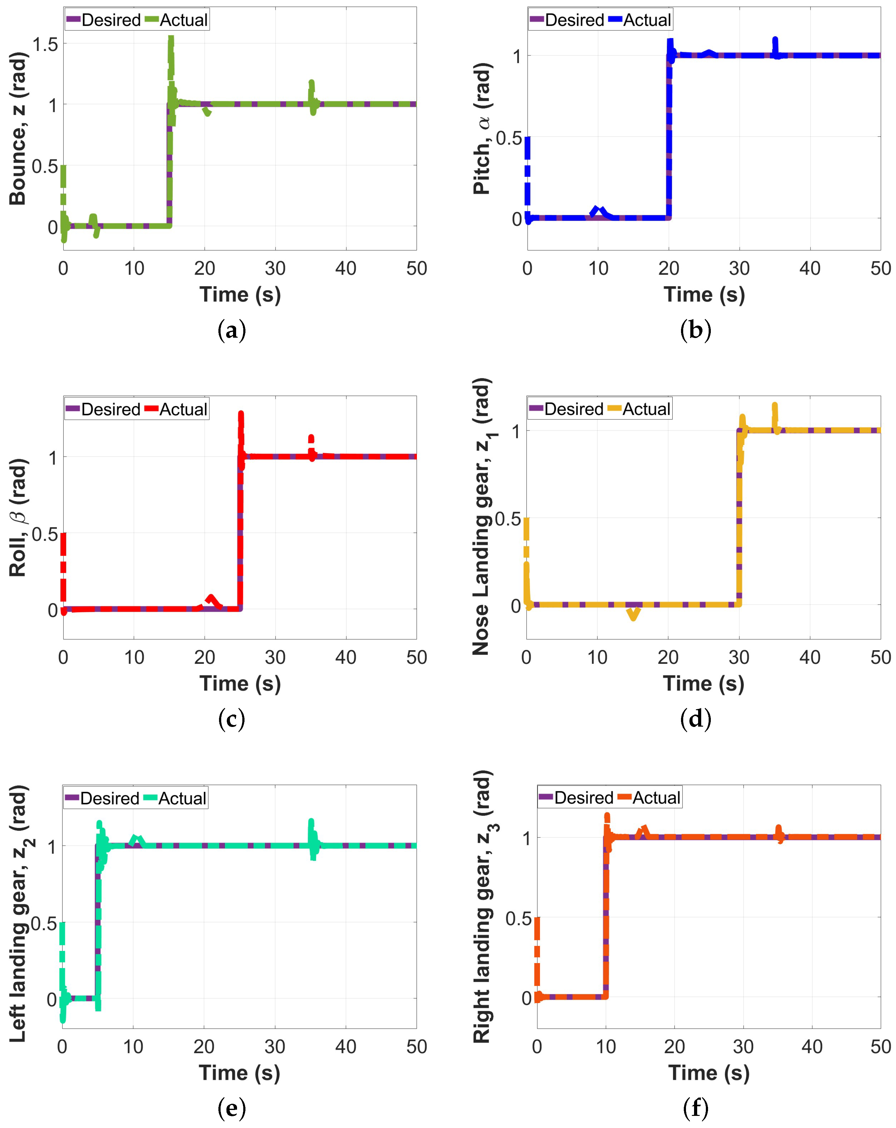
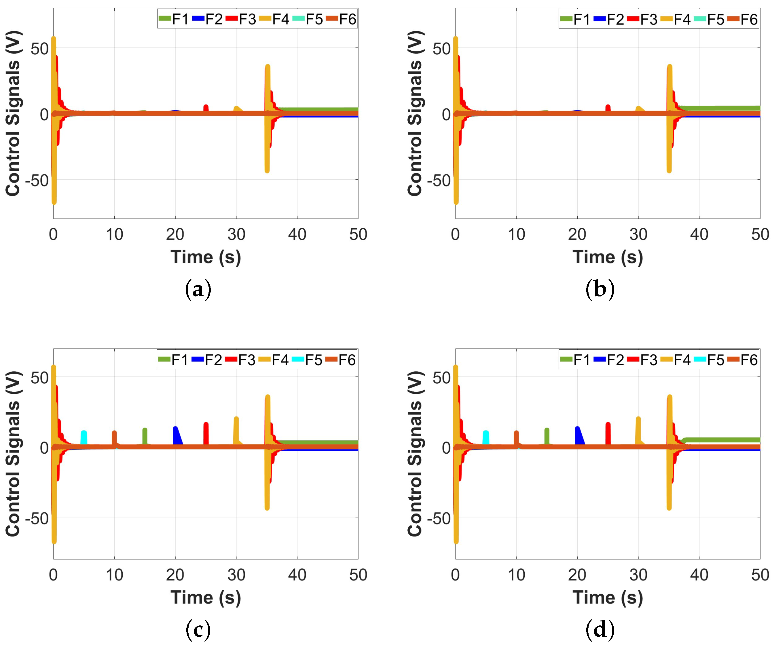
Lastly, both the LQG and PID controllers are tested under parameter variations to observe their behaviors. In the first case (case 1), the parameters of the 6-DOF aircraft landing gear shown in Table 1 are halved, and in the second case (case 2), the parameters of the landing gear are doubled. The response of the tracking errors and control signals of the two controllers to these two parameter variation cases are shown in Figure 10 and Figure 11. These results show that in spite of the varying parameters applied to the system, the LQG controller still maintains the system’s stability by decaying all errors to zero. The controller also does a good job of converging its control signals to zero despite the parameter variations. However, this is not the case for the PID controller, as its tracking errors do not decay to zero as easily as those of the LQG controller. The PID controller also does not easily bring the control signals of the landing gear system to its desired path, thereby affecting the stability of the system. Two performance metrics are also used to assess the performance of the LQG controller. These metrics are σ e , the integral of tracking errors, and σ c , the integral of the control signals, which are also used to assess the performance of the LQG and PID controller on the 6-DOF aircraft landing gear. These metrics are mathematically expressed as shown below [25]:
σ e = t 0 t f ( e z 2 + e α 2 + e β 2 + e z 1 2 + e z 2 2 + e z 3 2 ) d t
σ c = t 0 t f ( F 1 2 + F 2 2 + F 3 2 + F 4 2 + F 5 2 + F 6 2 ) d t
where e z , e α , e β , e z 1 , e z 2 , e z 3 represent the errors between the desired and actual positions of the system’s six degrees of freedom, z , α , β , z 1 , z 2 , z 3 , respectively. F 1 , F 2 , F 3 , F 4 , F 5 , and F 6 denote the control signals at bounce motion, pitch motion, roll motion, nose landing gear, left landing gear, and right landing gear, respectively. t 0 represents the initial time value and t f represents the final time value. Using the expressions of the two performance metrics, as shown in Equations (40) and (41), the results in Table 2 are obtained.
When the parameters are not halved or doubled, σ e and σ c for the LQG controller are 0.03651 and 1.774 × 10 3 , respectively, while those of the PID controller are 0.03805 and 1.881 × 10 3 , respectively. These results show that when the parameters are not halved or doubled, the LQG controller has a lower tracking index and control effort. When the parameters are halved, as in case 1, σ e and σ c for the LQG controller are 0.02151 and 1.139 × 10 3 , respectively, and those of the PID controller are 0.02181 and 1.154 × 10 3 . When the parameters are doubled, as in case 2, σ e and σ c for the LQG controller become 0.06112 and 2.251 × 10 3 , respectively, and those of the PID controller are 0.06208 and 2.315 × 10 3 . In both cases, the LQG controller has the highest tracking accuracy with the lowest control effort, thereby displaying that it is much more efficient at controlling the 6-DOF aircraft landing gear than the PID controller.
Figure 4. LQG controller tested on the 6-DOF aircraft landing gear: nonzero initial condition, nominal case, disturbances in (a) bounce motion; (b) pitch motion; (c) roll motion; (d) nose landing gear; (e) left landing gear; and (f) right landing gear.
Energies 16 06902 g004
Figure 5. LQG controller tested on the 6-DOF aircraft landing gear: nonzero initial condition, nominal case, disturbances in (a) tracking errors and (b) control signals.
Energies 16 06902 g005
Figure 6. Kalman filter estimate output from the 6-DOF landing gear: nonzero initial condition, nominal case, disturbances in (a) bounce motion; (b) pitch motion; (c) roll motion; (d) nose landing gear; (e) left landing gear; and (f) right landing gear.
Energies 16 06902 g006
Table 1. Physical parameters of the 6-DOF aircraft landing gear [10].
ParameterValueUnit
Sprung mass (M)22,000kg
Nose gear unsprung mass ( m 1 )130kg
Left gear unsprung mass ( m 2 )260kg
Right gear unsprung mass ( m 3 )260kg
Nose gear sprung mass stiffness rate ( k s 1 )6.73 × 10 5 N/m
Left gear sprung mass stiffness rate ( k s 2 )4.08 × 10 5 N/m
Right gear sprung mass stiffness rate ( k s 3 )4.08 × 10 5 N/m
Nose gear sprung mass damper rate ( c s 1 )1.43 × 10 5 N.s/m
Left gear sprung mass damper rate ( c s 2 )6.25 × 10 5 N.s/m
Right gear sprung mass stiffness rate ( c s 3 )6.25 × 10 5 N.s/m
Nose gear unsprung mass stiffness rate ( k t 1 )1.59 × 10 6 N/m
Left gear unsprung mass stiffness rate ( k t 2 )1.59 × 10 6 N/m
Right gear unsprung mass stiffness rate ( k t 3 )1.59 × 10 6 N/m
Nose gear unsprung mass damper rate ( c t 1 )4066N.s/m
Rear left gear unsprung mass damper rate ( c t 2 )4066N.s/m
Rear right gear unsprung mass stiffness rate ( c t 3 )4066N.s/m
Mass moment of inertia about x-axis ( I x )65 × 10 3 kg.m 2
Mass moment of inertia about y-axis ( I y )100 × 10 3 kg.m 2
Distance from CG to the nose landing gear (a)7.76m
Distance from CG to the horizontal axis of main landing gear (b)  1.94m
Distance from CG to the left main landing gear (d)3.8425m
Distance from CG to the right main landing gear (e)3.8425m
Figure 7. Kalman filter estimation error: nonzero initial condition, nominal case, disturbances.
Energies 16 06902 g007
Figure 8. PID controller tested on the 6-DOF aircraft landing gear: nonzero initial condition, nominal case, disturbances in (a) bounce motion; (b) pitch motion; (c) roll motion; (d) nose landing gear; (e) left landing gear; and (f) right landing gear.
Energies 16 06902 g008
Figure 9. PID controller tested on the 6-DOF aircraft landing gear: nonzero initial condition, nominal case, disturbances in (a) tracking errors; and (b) control signals.
Energies 16 06902 g009
Figure 10. The 6-DOF aircraft landing gear tracking errors’ responses to parameter variations: (a) LQG controller’s tracking error in case 1; (b) LQG controller’s tracking error in case 2; (c) PID controller’s tracking error in case 1; (d) PID controller’s tracking error in case 2.
Energies 16 06902 g010
Figure 11. The 6-DOF aircraft landing gear control signals’ responses to parameter variations: (a) LQG controller’s control signal in case 1; (b) LQG controller’s control signal in case 2; (c) PID controller’s control signal in case 1; (d) PID controller’s control signal in case 2.
Energies 16 06902 g011
Table 2. Performance metric comparison: 6-DOF aircraft landing gear.
Performance MetricLQGPID
σ e 0.036510.03805
σ c 1.774 × 10 3 1.881 × 10 3
σ e in case 10.021510.02182
σ c in case 11.139 × 10 3 1.154 × 10 3
σ e in case 20.061120.06208
σ c in case 22.251 × 10 3 2.317 × 10 3

5. Conclusions

This paper presents a novel approach to controlling an essential part of the aircraft system, the aircraft landing gear. The landing gear system, which is responsible for the landing and take-off of an aircraft, usually encounters landing vibrations. These vibrations are detrimental, as they can damage the aircraft’s airframe and provide an unpleasant ride for passengers. As such, this paper implemented a simple linear controller, the LQG controller, on the 6-DOF aircraft landing gear system to mitigate the challenges this system faces. By doing so, this paper not only accurately controls the landing gear system but also advances the industry, as the research conducted in this paper is one of the first attempts at applying an LQG controller on a 6-DOF aircraft landing gear. Firstly, the state space model of the landing gear system is derived, and then the mathematical model of the aircraft landing gear is calculated. The goal of the LQG controller is to control the system’s control signals, estimate its state variables, and make sure that the system remains on its desired trajectory, regardless of parameter variations or uncertainties. Therefore, the tests carried out on the performance of the controller monitored the output response of the controller to the desired step reference input. The LQG controller was also tested under conditions such as unexpected disturbances, parameter variations, nonzero initial conditions, and step changes. At nominal parameters, σ e and σ c for the LQG controller are 0.03651 and 1.774 × 10 3 , respectively, while those of the PID controller are 0.03805 and 1.881 × 10 3 , respectively. These results show that the LQG controller has a lower tracking index and control effort. In every testing scenario, the LQG controller did an excellent job at making sure the landing gear system stayed on the desired trajectory path regardless of the vigorous testing conditions. The performance of the LQG controller on the 6-DOF aircraft landing gear is also compared to that of the PID controller on the landing gear, and the results show that the LQG controller outperforms the PID controller in minimizing landing vibrations and ensuring passenger comfort. Future works around the research carried out in this paper could focus on implementing other novel control strategies on the aircraft landing gear to monitor the performance of the system. These control strategies could also be coupled with machine learning or AI algorithms for even better control of the landing gear system. On the other hand, the LQG controller could also be applied to other nonlinear systems that are otherwise too difficult to control and analyze. Leveraging the simplicity of the LQG controller could help simplify the complexity of nonlinear systems and lead to ease of computation.

Author Contributions

Conceptualization, C.M.N. and H.C.; methodology, C.M.N. and H.C.; software, C.M.N. and H.C.; validation, C.M.N. and M.A.; formal analysis, C.M.N., M.A. and H.C.; investigation, C.M.N., M.A. and H.C.; resources, H.C.; data curation, C.M.N. and H.C.; writing—original draft preparation, C.M.N. and M.A.; writing—review and editing, C.M.N. and M.A.; visualization, C.M.N., M.A. and H.C.; supervision, H.C.; project administration, H.C. All authors have read and agreed to the published version of the manuscript.

Funding

This research was funded by Natural Sciences and Engineering Research Council of Canada (NSERC), grant number 315082.

Data Availability Statement

Not applicable.

Conflicts of Interest

The authors declare no conflict of interest.

References

  1. Toloei, A.; Aghamirbaha, E.; Zarchi, M. Mathematical Model and Vibration Analysis of Aircraft with Active Landing Gear System using Linear Quadratic Regulator Technique. Int. J. Eng. 2016, 29, 137–144. [Google Scholar] [CrossRef]
  2. Pirooz, M.; Mirmahdi, S.H.; Khoogar, A. Robust force and displacement control of an active landing gear for vibration reduction at touchdown and during taxiing. SN Appl. Sci. 2021, 3, 410. [Google Scholar] [CrossRef]
  3. Ross, I.; Edson, R. An Electronic Control for an Electrohydraulic Active Control Landing Gear for the F-4 Aircraft; National Aeronautics and Space Administration, Scientific and Technical Information Branch: Washington, DC, USA, 1982. Available online: https://ntrs.nasa.gov/api/citations/19820014378/downloads/19820014378.pdf (accessed on 1 June 2023).
  4. Freymann, R.; Johnson, W. Simulation of aircraft taxi testing on the AGILE Shaker Test Facility. In Proceedings of the Second International Symposium on Aero elasticity and Structural Dynamics, Aachen, Germany, 1–3 April 1985. [Google Scholar]
  5. Freymann, R. An experimental-analytical routine for the dynamic qualification of aircraft operating on rough runway surfaces. AGARD Rep. 1987, 731. [Google Scholar]
  6. Freymann, R. An active control landing gear for the alleviation of aircraft taxi ground loads. J. Flight Sci. Space Res. 1991, 11, 97–105. [Google Scholar]
  7. McGehee, J.; Carden, H. Analytical Investigation of the Landing Dynamics of a Large Airplane with a Load-Control System in the Main Landing Gear; National Aeronautics and Space Administration, Scientific and Technical Information Branch: Washington, DC, USA, 1979. Available online: https://ntrs.nasa.gov/api/citations/19800004770/downloads/19800004770.pdf (accessed on 1 June 2023).
  8. Wignot, J.; Durup, P.; Gamon, M. Design formulation and analysis of an active landing gear. AFFDL-TR 1998, I, 71–80. [Google Scholar]
  9. Yu, H.; Xin, Y.; Jie, H.; Xue, C.-J. An experimental and numerical study on structural dynamic stress of a landing gear. J. Vibroeng. 2013, 15, 639–646. Available online: https://www.extrica.com/article/14518 (accessed on 1 July 2023).
  10. Sivaprakasam, S.; Haran, A. Mathematical model and vibration analysis of aircraft with active landing gears. J. Vib. Control 2013, 21, 229–245. [Google Scholar] [CrossRef]
  11. Li, C.; Jiang, J.; Wang, H. The optimization of active-control landing gear’s performance of absorber based on genetic algorithm. In Proceedings of the 32nd Chinese Control Conference, Xi’an, China, 26–28 July 2013; pp. 4194–4198. [Google Scholar]
  12. RezaToloei, A.; Zarchi, M.; Attaran, B. Application of Active Suspension System to Reduce Aircraft Vibration using PID Technique and Bees Algorithm. Int. J. Comput. Appl. 2014, 98, 17–24. [Google Scholar] [CrossRef]
  13. Attaran, B.; Zarchi, M. Oscillation Control of Aircraft Shock Absorber Subsystem Using Intelligent Active Performance and Optimized Classical Techniques Under Sine Wave Runway Excitation (TECHNICAL NOTE). Int. J. Eng. 2016, 29, 1167–1174. [Google Scholar]
  14. Pirooz, M.; Fateh, M. Impedance fuzzy control of an active aircraft landing gear system. Int. J. Dyn. Control 2019, 7, 1392–1403. [Google Scholar] [CrossRef]
  15. Arık, A.E.; Bilgiç, B. Fuzzy control of a landing gear system with oleo-pneumatic shock absorber 398 to reduce aircraft vibrations by landing impacts. Aircr. Eng. Aerosp. Technol. 2022, 399. [Google Scholar] [CrossRef]
  16. Horta, L.G.; Daugherty, R.H.; Martinson, V.J. Modeling and Validation of a Navy A6-intruder Actively Controlled Landing Gear System; NASA: Washington, DC, USA, 1999. Available online: https://ntrs.nasa.gov/api/citations/19990046416/downloads/19990046416.pdf (accessed on 1 July 2023).
  17. Pirooz, M.; Mirmahdi, S.H.; Moafi, S. Promoting both passenger comfort and aircraft handling of 6 DOF landing gear utilizing variable mechanical admittance approach. VIbroeng. Procedia 2020, 30, 79–85. [Google Scholar] [CrossRef]
  18. Gharapurkar, A.A.; Jahromi, A.F.; Bhat, R.B.; Xie, W.F. Semi-active control of aircraft landing gear system using H-infinity control approach. In Proceedings of the 2013 International Conference on Connected Vehicles and Expo (ICCVE), Las Vegas, NV, USA, 2–6 December 2013; pp. 679–686. [Google Scholar] [CrossRef]
  19. R.r.w. Robotik—EP.5: Feedback Control with Linear Quadratic Regulator (LQR). Rey’s Blog—Democratizing Robotics. 2020. Available online: https://rrwiyatn.github.io/blog/robotik/2020/07/19/lqr.html (accessed on 1 July 2023).
  20. Tedrake, R. Underactuated Robotics. 2022. Available online: https://underactuated.csail.mit.edu (accessed on 1 June 2023).
  21. Song, E.; Xu, J.; Zhu, Y. Optimal Kalman filter fusion with singular covariances of filter error. In Proceedings of the 2012 15th International Conference on Information Fusion, Singapore, 9–12 July 2012; pp. 1359–1365. [Google Scholar]
  22. Li, Q.; Li, R.; Ji, K.; Dai, W. Kalman Filter and Its Application. In Proceedings of the 2015 8th International Conference on Intelligent Networks and Intelligent Systems (ICINIS), Tianjin, China, 1–3 November 2015; pp. 74–77. [Google Scholar] [CrossRef]
  23. Zhang, H.; Basin, M.; Skliar, M. Kalman filter for continuous state-space system with continuous, multirate, randomly sampled and delayed measurements. In Proceedings of the 2005, American Control Conference, Portland, OR, USA, 8–10 June 2005; Volume 5, pp. 3462–3467. [Google Scholar] [CrossRef]
  24. Alazard, D. Introduction to Kalman Filtering. ISAE-SUPAERO. 2011. Available online: https://pagespro.isae-supaero.fr/IMG/pdf/introKalman_e_151211.pdf (accessed on 1 July 2023).
  25. Nkemdirim, M.; Dharan, S.; Chaoui, H.; Miah, M.S. LQR control of a 3-DOF Helicopter System. Int. J. Dyn. Control 2022, 10, 1084–1093. [Google Scholar] [CrossRef]
Figure 3. Block diagram of the LQG optimal controller.
Energies 16 06902 g003
Disclaimer/Publisher’s Note: The statements, opinions and data contained in all publications are solely those of the individual author(s) and contributor(s) and not of MDPI and/or the editor(s). MDPI and/or the editor(s) disclaim responsibility for any injury to people or property resulting from any ideas, methods, instructions or products referred to in the content.

